Little Beast - Subwoofer 8", 150W
by bobes360 in Workshop > Home Theater
5747 Views, 58 Favorites, 0 Comments
Little Beast - Subwoofer 8", 150W
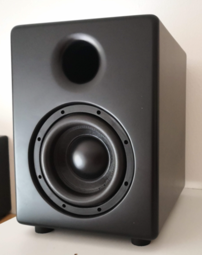


This project is the latest addition to my speaker addiction collection. My very first speaker is documented on this page as well, but the quality is nowhere close of this little beast. I am making speakers as hobby for almost 5 years, so I know a bit about them, but still consider myself a beginner. So far, I have made about a dozen of speakers, little or big, good playing or not. This project follows my journey of making my first subwoofer. I wanted it to be relatively small and to be able to play down to about 30 Hz. I mainly listen to songs, but I also love a good sounding movie.
I found interesting thread on Czech forum about this little 8" subwoofer, which is supposed to sound really good and is sold for only 38 EUR. So, following some advices, I modelled the MDF enclosure, used WinISD software to tweak its dimensions and decide the best port diameter. Then I found suitable components, fabricated the enclosure and with the help of my father painted it matte black colour.
I am no expert, have no measuring devices, but I love the results. I have it connected to my other homemade speakers and I am enjoying every bit of it playing. The discovery of whole new level of detail in some songs is exactly why I made it. (If anyone finds any mistakes in any part of my instructable please let me know I would like to improve myself).
Supplies
Supplies needed for this build are as follows:
- Subwoofer: Q338A
Power: 250W AES / 500W peak
Frequency range: 35 Hz – 2.2 kHz
Sensitivity: 82 dB/W/m
Impedance (dual coil): 2; 8 Ohm
Price: 38 Eur
Link: https://www.hadex.cz/q338a-repro-203mm---8-subbaso...
- Amplifier: Monacor SAM-300D
Power output: 300W at 4 Ohms, 150W at 8 Ohms
Variable low-pass filter: 40-200 Hz (18 dB)
Integrated bass boost of approx. 3 dB at 40 Hz
Price: 150 Eur
Link: https://www.soundimports.eu/en/monacor-sam-300d.ht...
- Bolts with nuts:
8x M5x25 bolts with self-tapping nuts
Link: https://www.hadex.cz/q692-sroub-m5x25mm-cerny-se-s...
- Screws:
10x D3,5x16 mm
- Speaker feet:
4x 38x20mm speaker feet
Link: https://www.hadex.cz/q645-nozka-pod-reprobox-38x20...
- Dampening material:
Link: https://www.soundimports.eu/en/visaton-damping-mat...
- Port tube:
1x 1m DN75 PVC tube, 1x DN75 87° PVC elbow
Links: https://www.topenilevne.cz/osma-htem-trubka-dn-75-...
Simulation Software
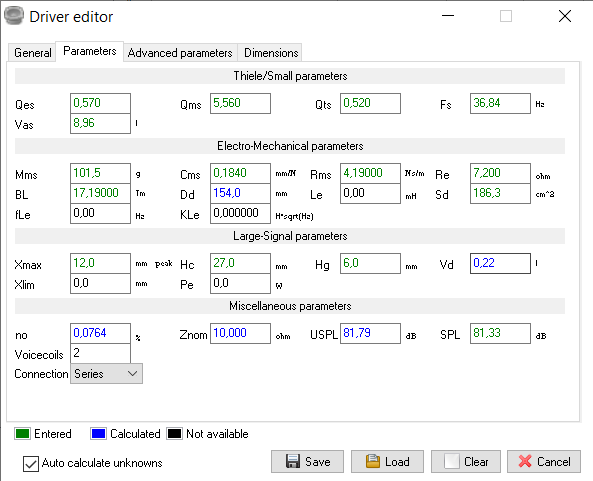
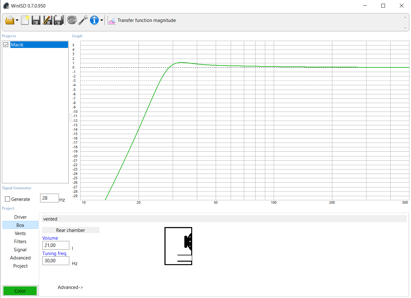

Using free software WinISD for the second time in my life I predicted the behavior of this speaker. This program is quite easy to use and there are many nice tutorials on how to use it. I will therefore not go into much detail.
First I needed to enter all the speaker parameters, so the software can do its magic and calculate the best bass reflex enclosure with all the important dimensions.
In the second picture you can see the simulated frequency response of the speaker. With a little bit of experimenting a decided to use 21l cabinet with tuning frequency of 30 Hz. The cabinet is a little bit bigger than the recommended one on the website which supplies the speaker. That is because of the enormous length of port which would be 680 mm. By increasing the box volume to 21 l the port shrinks to 575 mm which seemed more reasonable for me (see third picture). Final length of my port is about 520 mm but the 90 degree bent in port should result in tuning the port lower.
The third picture shows simulated port air velocity. The peak should not exceed 20 on the y scale of the graph. You need to fill in the important values in signal row first thought.
I must say that this software seems to be calculating quite truthful results. Using only my ears and signal generator, I would say, that this subwoofer can easily play down to 28 Hz, with a little noticeable peak at 32 Hz. The only problem is chuffing of the port at 26 Hz, which I do not know how to get rid of. Using dampening material inside speaker helped, but it did not disappeared completely. Although playing that frequency while not being right in front of the speaker results in hearing more of rattling of different stuff around the house, rather than the port noise.
Downloads
Modelling Software
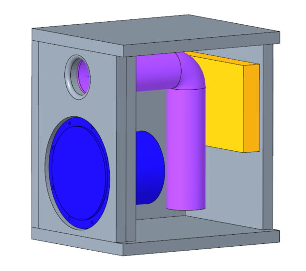
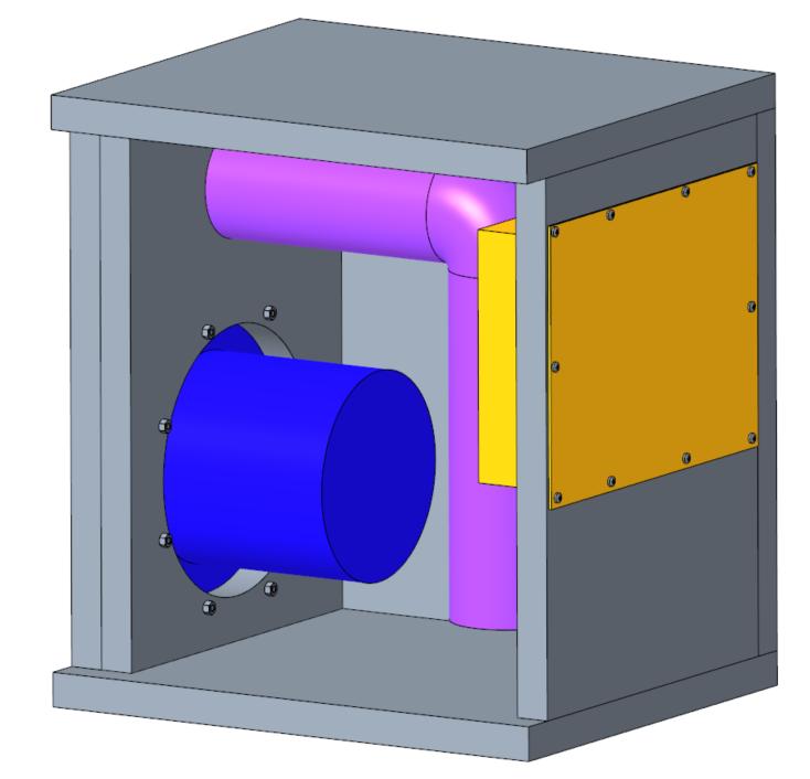
For better visualization of the dimensions I used Creo 4.0 as my 3D modelling program. Using this software, I modelled simplified version of the subwoofer, port, amplifier. Then added all the necessary wooden plates to make the enclosure. Because I had access to 23 mm thick MDF boards, I modelled it to this dimension. If you are going to use wood with different thickness you need to modify some dimensions.
You also need to add to the overall volume of the box all of the components inside. My box has inside volume of 27,7l, but with all of the components inside it is just slightly above 21l.
For anyone interested I included .STP file of the Creo assembly as well as .PDF file with drawings and all of the dimensions. It is all in Czech, but I think it is all quite self-explanatory with this instructable. (dimensions are in mm)
Fabrication of the MDF Panels


Finally, after many hours of computer work comes the time of actually making something. The whole speaker cabinet is made from 23 mm MDF board. This process is quite simple, but every speaker teaches me something new which I can use in future.
Firstly, I cut all of the wooden panels to dimensions while marking them, so I do not confuse them later. The square hole for the amplifier is cut using the combination of drill press and jigsaw followed by hand sanding (picture 1 and 2). The two holes for port are cut with circle cutter drill attachment (picture 3).
I was very afraid to cut the holes for the subwoofer, because I don't have woodworking router and the circle cutter attachment, I used for making those smaller holes, wasn't big enough. (I used two MDF boards for the front for added strength and to sink the subwoofer) But with a little bit of patience, I managed to make them somewhat straight and even with the combination of drill press, jigsaw and sand paper drill attachment I made (picture 6 and 7). For this attachment I used wooden cut-out from the circle cutter, added two notches barely big enough for the sand paper and then simply slid the sandpaper in. It is not the best tool, but it served its purpose and evenly sanded the holes for speaker.
Finishing of the MDF Panels


The next thing on the list was to use little dremel tool and hand sanding to make radius on the port hole, so the air coming in and out is not restricted (picture 1). The different hole diameters of the port holes are made this way in order to glue the port tube into the mounting panel while the covering panel is just an extension of the port tube.
In the second picture you can see finished covering panel with smooth radius on the opening of the port and mounting panel beneath with all the necessary holes for screws. It is also important to hammer those self-tapping nuts to the back of the mounting panel before glueing, because later it would be much more difficult (picture 3). It is also recommended to glue those nuts in place (picture 4), because I had problems in other speakers where they were falling out.
Finally, I used the circle cutter to cut out a ring (picture 5), which I than sanded down to make a radius for the air moving in and out of the end of the port inside the cabinet.
Glue Up Time


Now that all the parts are ready, it is time to join them together. For the two front plates I used wood glue and several clamps (picture 1 and 2). Then I used construction glue, which is supposed to foam up a bit to glue all of the remaining joints. This should make sure that all of the imperfections and cavities are filled with glue and the air cannot escape from the box. I also did not have clamps big enough to squeeze the enclosure, so I used duct tape tightly wrapped around the speaker instead.
Fourth and fifth picture shows the finished box. (Note the different orientation - the final speaker is situated upside down because reasons.)
The Quick Cleanup


This step is not quick at all, I spend the whole night sanding and finishing of the box. First you need to remove any excess glue with a knife. Then I used belt sander to sand all of the faces (picture 3). Next step was to round all of the sharp edges with the belt sander and then handsand the whole thing with at least P100 sand paper grid so there are no visible marks from the belt sander.
After quick air blasting you see all of the cavities in the seams, which need to be filled up. You might want to use some wood chisels or knives to deepen them to make it easier for the filler to stay in the cracks (picture 5). I used wood filler to cover those up. After this comes another round of hand sanding and air blasting, which reveals more imperfections, that you need to fill up...
Anyway, after you loose your will to continue filling and sanding you are basically done with the enclosure fabrication.
Colouring


For the colouring I decided to use matte black paint - daring right? This entire step was done by my father, who works with colours for wood for more than 20 years, so I had confidence in the outcome. However, oblivion or miscommunication resulted in him standing the speaker upside down on his colouring platform (picture 2). Which led to markings on the bottom/top side. But because it doesn't matter at all, I went with this orientation instead.
First 2 layers of paint consisted of clear lacquer. This step ensures the sealing of the MDF fibers. It roughens the surface as the MDF fibers rises, therefore sanding is required. The next layer of paint is white adhesive base layer followed up by two final black layers. With sanding in between of all of the layers. It is also important to have the port attached, so that its inside doesn't stay grey, but is rather painted black.
In total he used 1l of clear lacquer, and the final mass of this speaker increased by almost 400g after all the paint dried.
It is incredibly difficult to produce painted surface with no impurities, because every speck of dust is visible, but my father didn't let me down as always and made this piece of ugly wooden cube into a design masterpiece.
Then I just inserted the amplifier and secured it with screws to predrilled holes. The subwoofer is then connected to the speaker wires from the amplifier and bolted down thanks to the self-tapping nuts, that ensures longer life for the speaker mounting.
Some Numbers


I spent two whole weekends evenings (from 17-24:00) making this speaker. My father spent several hours divided in 4 days painting and sanding it.
The total cost of this speaker without shipping fee, cost of wood and cost of paint (it was old paint meant to be disposed of) is roughly 210 Eur.
The speaker can play down to 28Hz without problem and even with a bit weaker amplifier (speaker coils are in series, therefore 8 Ohms total impedance) can be very loud.
In conclusion I am very happy with the outcome. The main surprise was watching action movies with it and hearing all those frequencies shaking the whole house. In the future I plan to try to turn it up more to see what it is really capable of, but because of shared living, it is not possible at the moment.
Hope you liked my build and I would love to hear some points, comments, advices from anyone.