Low Profile Vise for Desktop Size Milling Machines.
by matterbach in Teachers > 9
103 Views, 1 Favorites, 0 Comments
Low Profile Vise for Desktop Size Milling Machines.
.jpg)
.jpg)
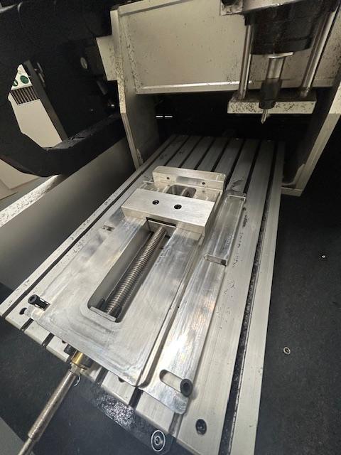
Presently there are very few if any good options for workholding for use on the latest generation of desktop sized milling machines. In the world of education they present a game changer for instruction in that students can get access to a CNC milling machine in a size that makes it possible in just about any classroom. Based on my classroom's struggles on holding projects in the machines, I designed this project in conjunction with Scott Seacrist at Lincoln High School in Lincoln California as a solution to easy workholding for a desktop sized mill with minimal Z height and minimal moving jaw lift. The result is working well and allows students to load material into these machines with a minimum of fuss. I am not going step by step for each of the parts below, that would make for an incredibly complicated instructable. instead these are basic instructions with full fusion files for use using your particular machines and accessories, which you will have to adapt to your own conditions.
Downloads
Supplies
.jpg)
.jpg)
This project requires access to CNC Mill with a 12"X12"X12" or larger capacity and a CMC or manual lathe with a 1" diameter capacity and 15" of length. The irony is not lost on me that you need a large CNC machine to make the vise for a small CNC machine, but this instructable is intended for educators with access to this equipment either in school or through an educational partner.
If the vise is made in aluminum please confine its use to small scale desktop sized milling machines with low horsepower spindles. Using this as a second vise on a full size machine would likely lead to breakages unless the whole project is re-developed in steel.
Cutters: not limited to 3/4", 1/2", 1/4" and 1/8" endmills
1/2-13, 1/4-20, 10-32 and 8-32 taps with accompanying tap drills
Assorted deburring tools or chamfer mills
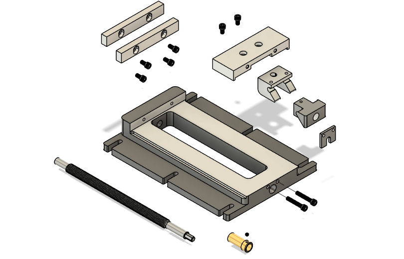
Metal blanks needed
2X7X10 rectangular aluminum block for vise body
4.125 X .75 X 2.0 rectangular aluminum block for moving jaw upper
1.5X2X3 rectangular aluminum block for moving jaw lower
1.5X2X3 rectangular aluminum block for moving jaw driver
2, 3/8X1/2X4-1/8" 1.5X2X3 rectangular aluminum blocks for jaw liners
1, 1/2-13 UNC threaded steel rod 10 inches long for drive screw
1, .750 X 2" long round bronze bar
1, 1.0 X1.0X.125 steel rectangular block for drive screw bearing plate
Assorted socket head cap screws, 10-32 and 8-32 thread sizes
1, 8-32 set screw .125 long
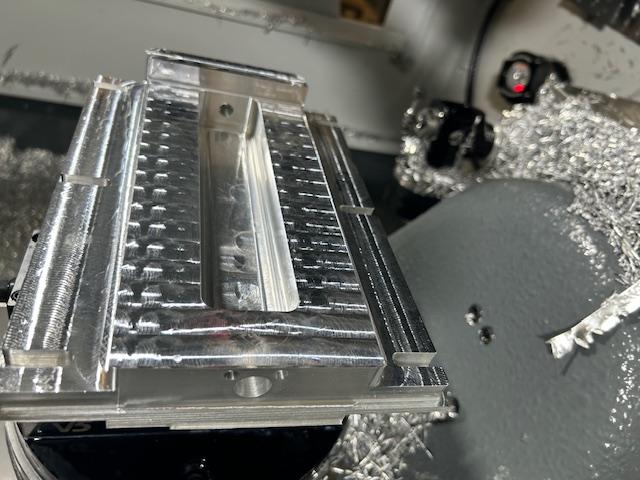
Making the Vise Solid Jaw.
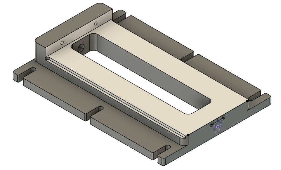
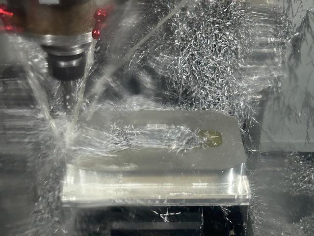
This is the most complicated part of the vise and also the core base unit critical to the success of the project. This unit can be made on a traditional 3 axis mill in 4 holds, or a 5 axis mill with only 2. The attached F3d files were used to create this project in 2 holds on a 5 axis machine.
Downloads
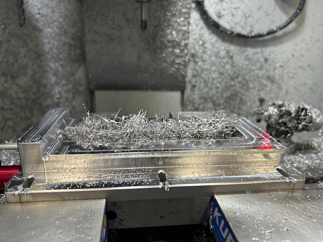
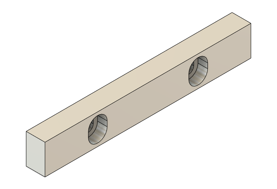
Making the Moving Jaw Driver
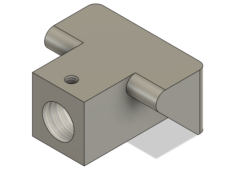
This part of the vise requires multiple holds and a 1/2-13 UNC, and 8-32UNC holes to be tapped into the part, as the holes meet in the middle of the unit, deburring is critical to making this part fit smoothly. This unit can be made on a traditional 3 axis mill in 4 holds, or a 5 axis mill with only 2. The attached F3d files were used to create this project in 2 holds on a 5 axis machine, using a tab off procedure to insure that the complete part needed minimal operations after the first hold.
Downloads
Making the Moving Jaw

When initially produced, the lower and upper units of the moving jaw were split into two pieces to ease workholding issues, however I have successfully made this as one solid piece in 4 holds, or in two pieces with 6 total holds. Please use whichever method you would prefer for these parts. The vise will be stronger as 1 piece but it will be easier especially for students to make if it is divided into its two constituent solids as above.
Making the Drive Screw
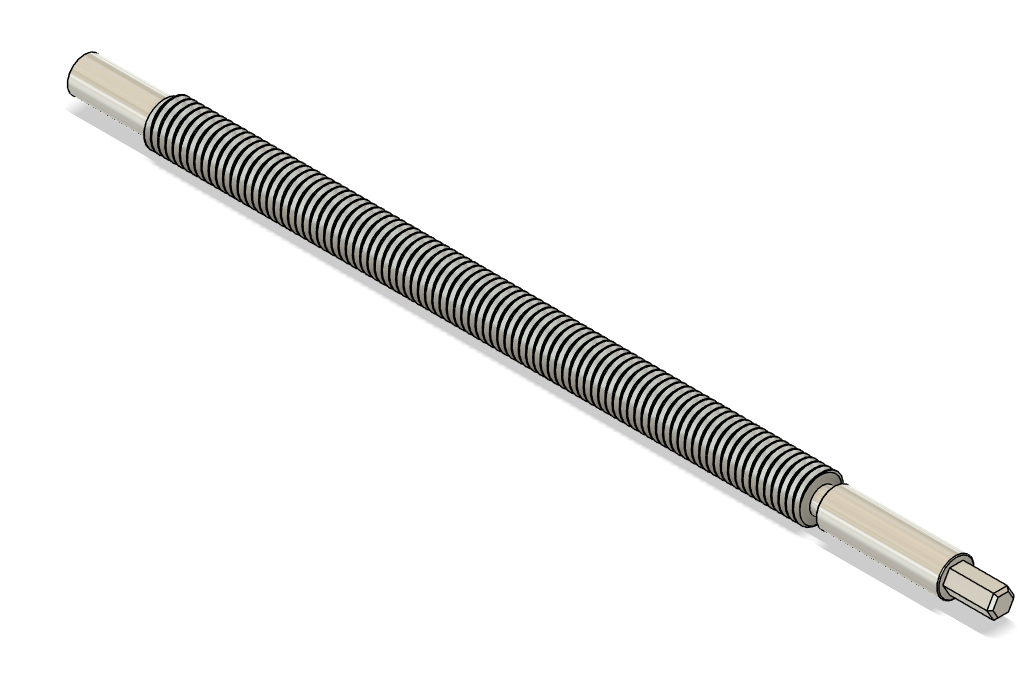
This part of the project is most easily made using a pre-threaded rod. The whole part can be made in a standard manual or CNC lathe using 2 holds and just a profiling tool and a grooving tool. The hex head area is easily completed using a manual or CNC milling machine, and a hexagon collet block.
Downloads
Make the Drive Sleeve
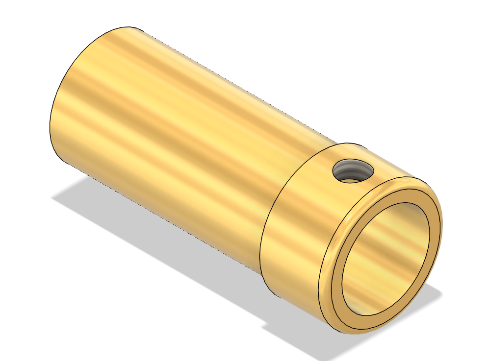
The drive sleeve is a sinple bronze bushing that permits the drive sleeve to be inserted into the vise, but also spin easily. the 8-32 UNC cross hole in the side of the part is often easiest to put in after it is turned on a lathe. the part is simple enought to be made on a CNC or manual lathe with minimal fuss.
Downloads
Make the Drive Screw Bearing Surface
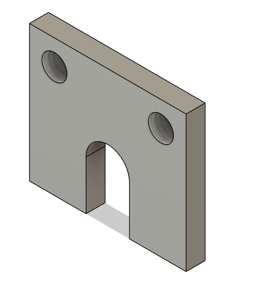
The Drive Screw Bearing surface provides a locking surface for the steel screw to push against. It can easily be made on a Manual or CNC milling machine from .125 thick steel stock. If you have a CNC Laser cutter this might be a candidate for that as well, with all but the 10-32 UNC holes being created and the tapping done by hand after the fact.
Downloads
Creating the Jaw Liners
This pair of parts can be made with aluminum or steel as you would prefer. If you have made the moving jaw in two pieces this part is essential to keeping the sliding jaw rigid, and do not skip it. They have been designed to be reversible so you can flip the jaw upside down for a fresh upper surface. I have also considered 3d printing these with a similar bolt pattern but cut for a specific project on top.
Downloads
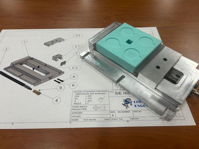
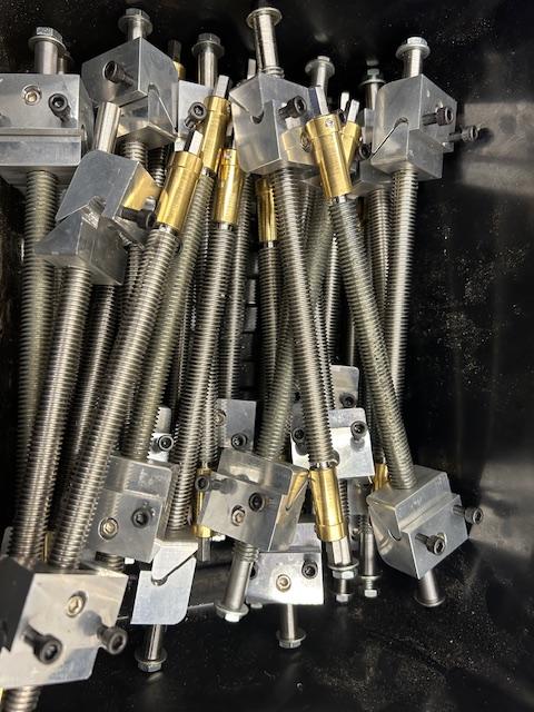
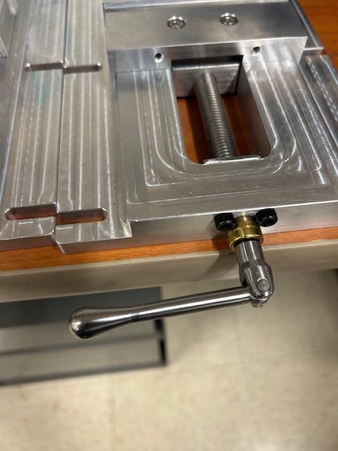
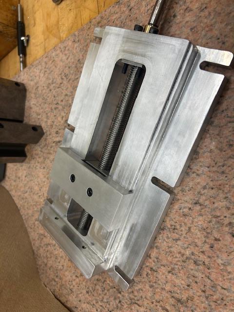
Assemble
.jpg)
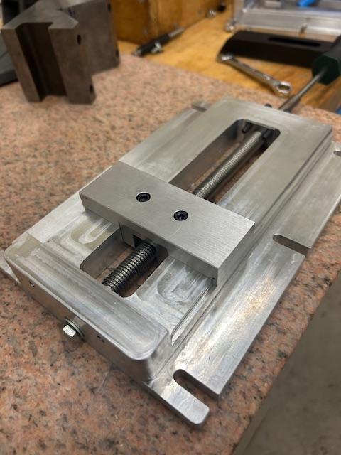
Assembly is fairly straight forward. Light filing of the interior surfaces of the moving jaw may be necessary in order to get the assembly working smoothly. If parts are out of spec often filing can be used to bring them into size if a manual mill is unavailable.
One of my students even fashioned a wrench for this project made like one from a standard machinist's vise, otherwise this vise can use a 1/4" hex bit driver to open and close, I would avoid closing too aggressively though to avoid damaging parts.