Measuring MCP4728 DAC Accuracy Using TI ADS1115 ADC and a Stable Power Supply Including INL, DNL and Zero Offset
by kevinjwalters in Circuits > Microcontrollers
110 Views, 0 Favorites, 0 Comments
Measuring MCP4728 DAC Accuracy Using TI ADS1115 ADC and a Stable Power Supply Including INL, DNL and Zero Offset
This article takes a look at the accuracy of the Microchip MCP4728 digital-to-analogue converter (DAC). This DAC features four 12 bit channels with an optional internal voltage reference. A microcontroller can be used to generate triangle waves from the DAC and these can be measured with a precision analogue-to-digital converter (ADC) like the 16bit Texas Instruments ADS1115.
A CircuitPython program was used on a Cytron Maker Nano 2040 to perform the tests. A Texas Instruments ISO1540 was used to isolate the i2c bus, this allows the both the DAC and the ADC
- to use a power supply independent of the potentially noisy USB-derived one from the microcontroller board and
- run at a voltage higher than 3.3V.
The MCP4728 DAC is advertised as having good linearity within the 100-4000 code range. This range was examined to verify this and the extremities were explored. This testing could also be useful to
- select the optimal channel for a particular application,
- compare the performance of different DACs,
- analyse the performance of a second ADC (below the resolution of the ADS1115),
- check for low-quality counterfeit ADC/DACs or damaged devices or
- check how/if the DAC output varies with a different power supply using internal and Vdd voltage references.
Batteries were used to provide stable, very low-noise power. The overall hardware setup features the typical array of breakout boards, dangling cables and a breadboard common with hobbyist projects. The results show this can perform well despite its inherent drawbacks.
This builds on some of the work in Microrack Modular Synth: MIDI to CV Using Cytron Maker Nano 2040 and Adafruit MCP4728 DAC With I2C Isolation and An Imperfect Comparison of Arduino Analogue and Digital Inputs: UNO R3, Leonardo, UNO R4 Minima and UNO R4 WiFi.
This project involves fairly simple soldering to attach some headers to the DAC board and construct a breadboard power supply kit.
Supplies
- Cytron Maker Nano 2040**: DigiKey | PiHut
- 2x male-male short Qwicc/STEMMA QT cable: DigiKey | PiHut
- Adafruit MCP4728 Quad DAC with EEPROM: DigiKey | PiHut
- Adafruit ISO1540 Bidirectional I2C Isolator: DigiKey | PiHut
- Some solid-core AWG22 wire in red and black and another colour (and wire strippers) - male-male jumper wires could be used but low quality cables may affect accuracy.
- Texas Instruments ADS1115 (take care to avoid fakes)
- Seeedstudio
- Grove - 4-Channel 16-bit ADC(ADS1115) - used in this article: seeed studio | PiHut
- Grove - 4 pin Male Jumper to Grove 4 pin Conversion Cable (5 PCs per Pack): seeed studio | PiHut
- Adafruit
- ADS1115 16-Bit ADC - 4 Channel with Programmable Gain Amplifier - STEMMA QT / Qwiic: PiHut | DigiKey
- Another male-male short Qwicc/STEMMA QT cable: DigiKey | PiHut
- Battery pack with 2.1mm centre-positive barrel connector or a pair of wires.
- A 5 or 6 AA pack is good for using batteries including rechargeable (NiMH): DigiKey | PiHut
- A 4 AA pack could be used with fresh alkaline batteries but as they discharge the voltage will drop and a linear regulator will not be able .
- Some batteries - NiMH rechargeable ones are useful for their low voltage drop as they discharge.
- Breadboard power supply with a linear regulator.
- Adafruit: Adjustable breadboard power supply kit - this is very useful as it has an adjustable range which can be used to produce voltages slightly above 5.0V: DigiKey | PiHut
- Low-brand "MB102" breadboard power modules with barrel connector. These are viable but will only provide 5.0V. The omnipresent AMS1117 regulators have a large dropout voltage specified as 1.1V, any protection diodes will add to this voltage drop.
- Any other breadboard power supply (like the DFRobot Breadboard Power Supply 5V/3.3V) which has
- a terminal block or (centre-positive) barrel connector,
- a voltage drop from the linear regulator and any protection diode suitable for the batteries in use (including when they have discharged to some extent) and
- can provide a fixed 5.0V or an adjustable voltage covering the 5.0V-5.5V range.
- Solder, soldering iron to attach two rows of header pins to DAC board and construct a power supply kit if necessary.
- 100k resistor if you wish to load the DAC output. Anything above 5k is appropriate.
** Or any CircuitPython-compatible board ideally with Qwicc/STEMMA QT connector, e.g. a Pimoroni Tiny 2350.
Hardware Setup I
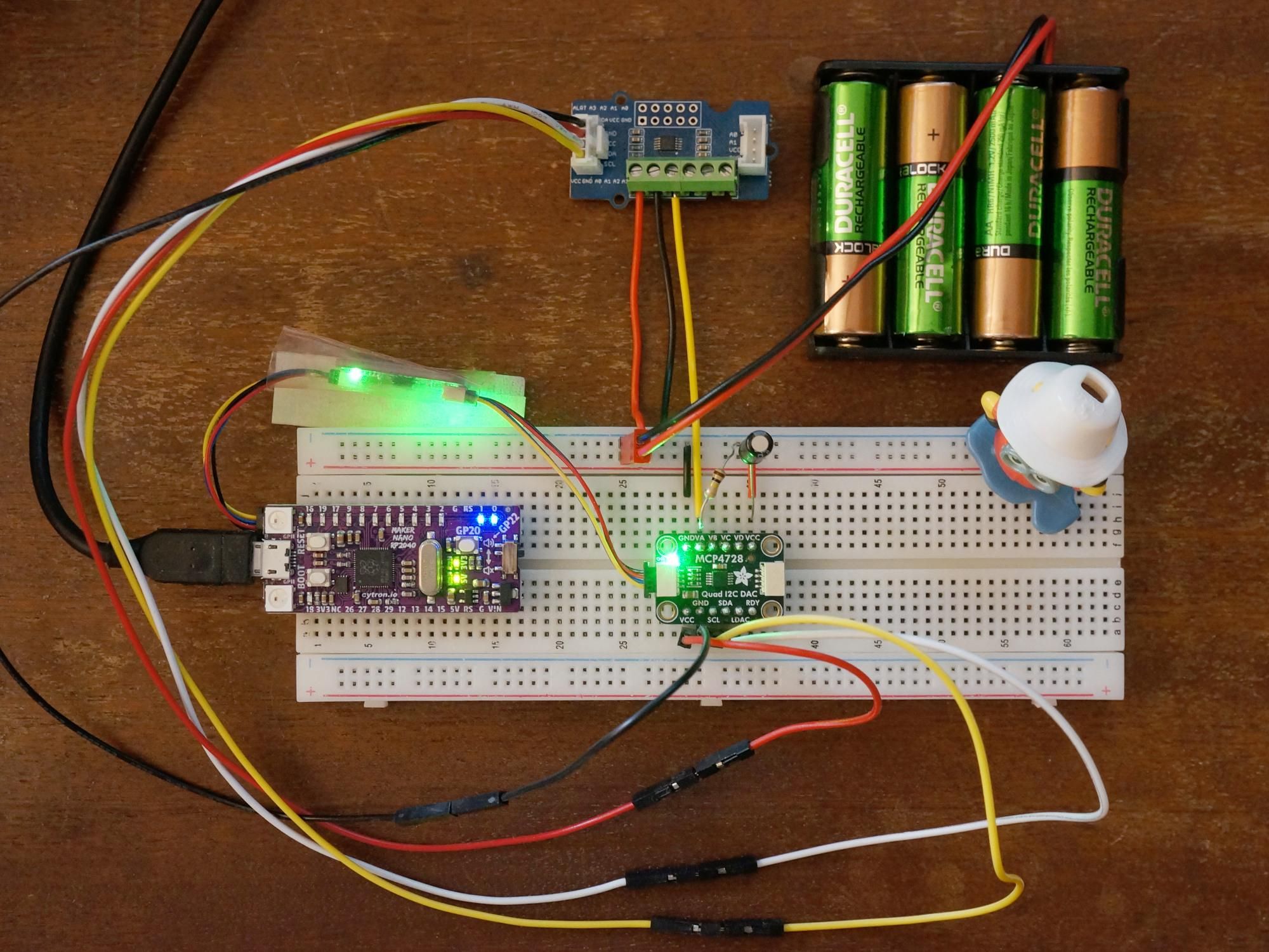
The first measurements were taken with a setup similar to the one shown in the photograph above. The Cytron Maker Nano 2040 board is connected to an Adafruit ISO1540 Bidirectional I2C Isolator board with a STEMMA QT cable. The Adafruit ISO1540 board is not connected to the breadboard and has been placed inside a piece of pink anti-static bag sealed on one side with masking tape to reduce the risk of something conductive touching the underside and shorting the pads.
The isolator board then connects to the Adafruit MCP4728 Quad DAC board on the breadboard. A 4xAA battery pack filled with rechargeable (NiMH) batteries powers one pair of rails on the breadboard. A Grove cable with female sockets and four additional male-male jumper wires connect the Grove ADS1115 to the isolated i2c bus and power available on the lower pins of the MCP4728 board. The Grove ADS1115's terminal block has a ground (black wire) connecting to the negative rail on the breadboard and input A0 (yellow wire) connecting to the VA output of the DAC.
This photograph also features some other components added later for experimentation, a 100k resistor to load the DAC output, a 10uF electrolytic capacitor across the battery-powered rail and a red wire providing a duplicate power connection to the Grove ADS1115 via its terminal block.
The recommended supply voltage ranges from the datasheets for the isolated devices are listed below.
- MCP4728: 2.7V to 5.5V (absolute maximum 6.5V).
- ISO1540: 3.0V to 5.5V (absolute maximum 6.0V).
- ADS1115: 2.0V to 5.5V (absolute maximum 7.0V).
Rechargeable batteries which have been fully charged and just removed from the charger can have a surprisingly high voltage, 4 NiMH batteries can produce 5.6V with very light loads for a while - this is above the maximum value but not the absolute maximum for these devices.
Software
The software is fairly simple. It initialises the ADC and DAC and then runs a set of tests with various combinations of ADC mode and DAC voltage reference. Each tests ramps up the DAC value from 0 to 4095 and then back down from 4095 to 0 producing a triangle wave output. An ADC measurement is taken for each DAC value.
The channel can be set at the top of the program by adjusting the MCP_OUTPUT_PIN variable.
The ADS1115 is set to a sample rate of 128 samples per second. This is the fastest rate where the device still has maximum effective resolution at 2/3 gain and VDD=3.3 (the datasheet doesn't have tables for other supply voltages).
Output Sample
This is a sample of the output from running the test. The fields are
- DAC output channel name, A-D.
- ADC input number, 0-3.
- S or C for single-shot or continuous ADS1115 mode.
- The DAC voltage reference, max means use the power supply voltage, aka Vdd.
- The test number for this combination of settings, starts at 0.
- The DAC output value (code), this is a 12bit number** for the MCP4728, i.e. 0-4095.
- The voltage measured by the ADS1115.
- Any readings from an additional ADC, NA for not available.
The maximum voltage can be seen at DAC code 4095. For battery power this voltage will decrease slowly over time as the batteries discharge. When the voltage reference is set to Vdd the fall will affect the DAC output. This should be slow enough that the maximum value can be extracted for each ramp up and ramp down test and be representative for that test. The ramp up/down only takes a few minutes at most.
This output should have an indication of the time for each output line. This was an accidental omission. A future revision of the software will add this.
The program changes the sampling mode of the ADS1115. This can only be done by instantiating a new ADS1115 object for each mode change at the moment due to a bug.
** The CircuitPython interpreter and libraries tend to use values which are (normalised) to 0-65535 for DACs and ADCs.
Software Installation
If you are not familiar with CircuitPython then it's worth reading the Welcome to CircuitPython guide first.
- Install the latest version of CircuitPython (10.2.1 on July 2024) from https://circuitpython.org/ - this process is described for a similar RP2040-based board in Introducing Adafruit Feather RP2040: Installing CircuitPython.
- adafruit-circuitpython-cytron_maker_nano_rp2040-en_GB-10.2.1.uf2
- Verify the new installation by connecting to the serial console over USB. The REPL prompt shows the version number. The version can also be checked by inspecting the boot_out.txt file on the CIRCUITPY drive.
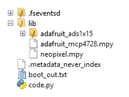
- Install these libraries from a recent bundle from https://circuitpython.org/libraries into the lib directory on CIRCUITPY:
- adafruit_ads1x15
- adafruit_mcp4728.mpy
- neopixel.mpy
- Download the mcp4728-ads1115-test.py file to CIRCUITPY by clicking on the Raw button on the page and then Save link as...
- Rename or delete any existing code.py file on CIRCUITPY, then rename mcp4728-ads1115-test.py to code.py. This file is run when the CircuitPython interpreter starts or reloads.
- Unmount (eject) the CIRCUITPY drive.
The versions used for this article were:
- CircuitPython: 10.2.1
- CircuitPython library bundle: adafruit-circuitpython-bundle-10.x-mpy-20260725
Initial Results From Testing With Battery Power - a First Glance
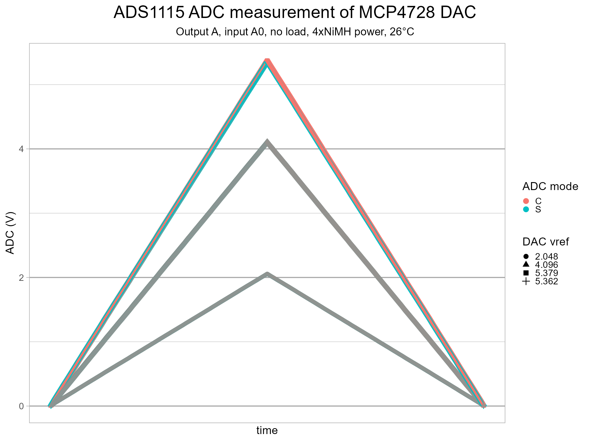
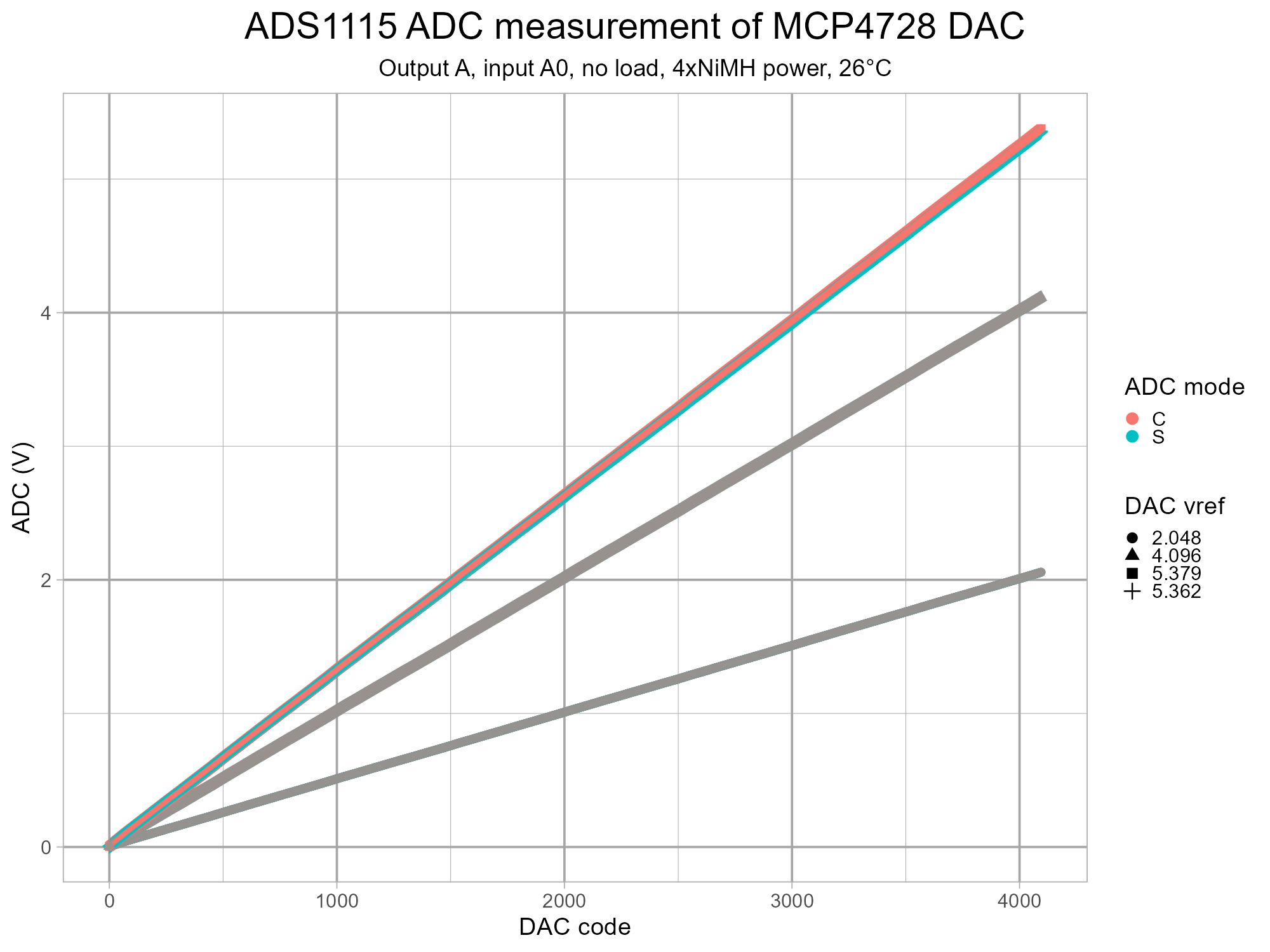
The first plots show nice straight lines from the DAC as would be expected. A close inspection of the second plot reveals the single-shot (S) ADC measurements might be a bit more variable and might be lower at high voltages than the continuous ones (C).
Initial Results From Testing With Battery Power - a Closer Look
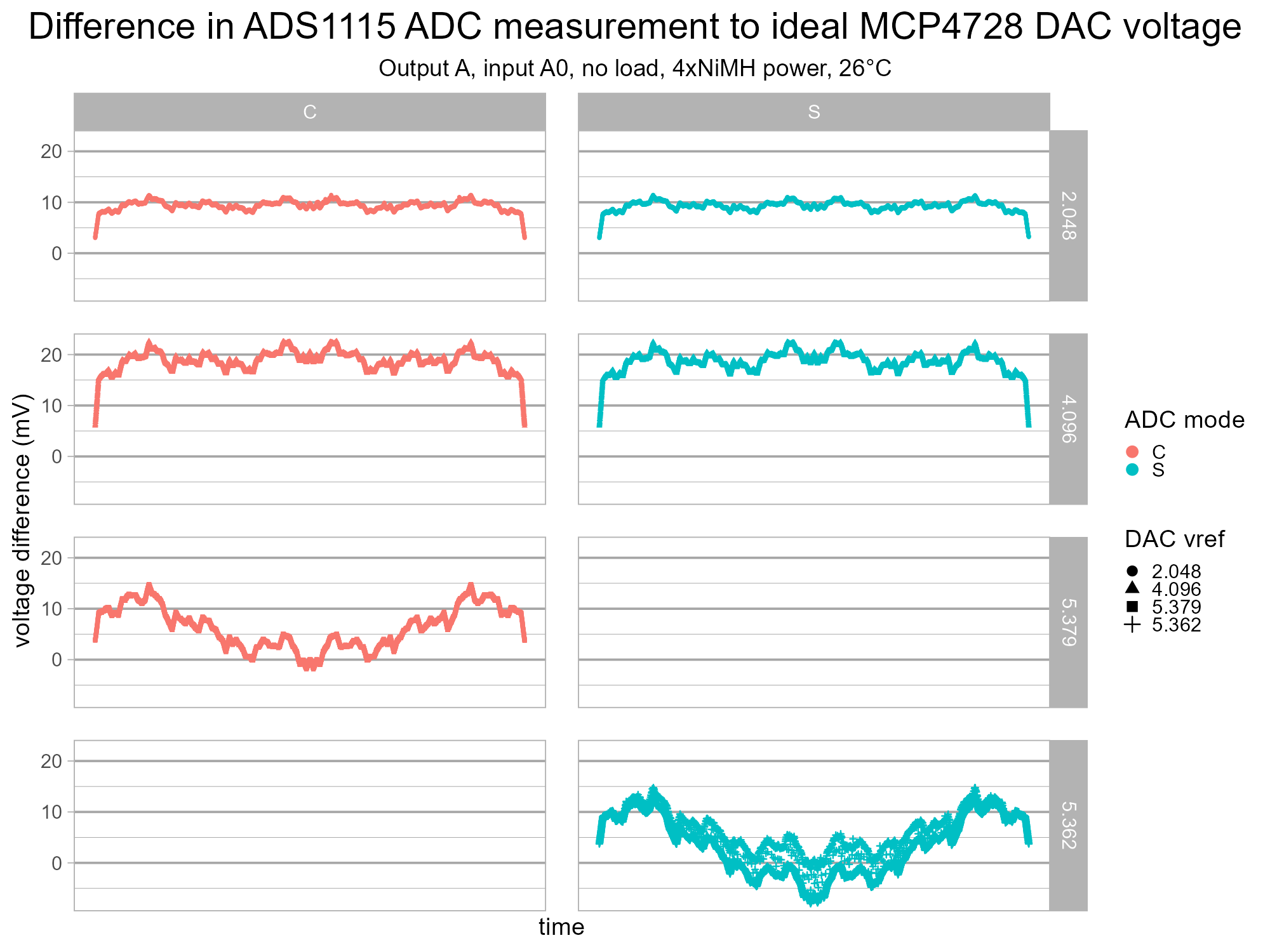
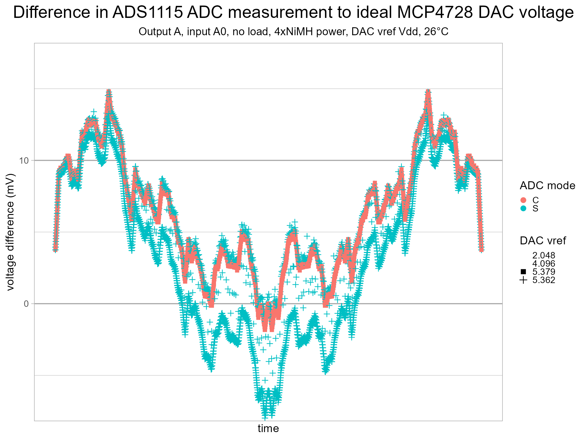
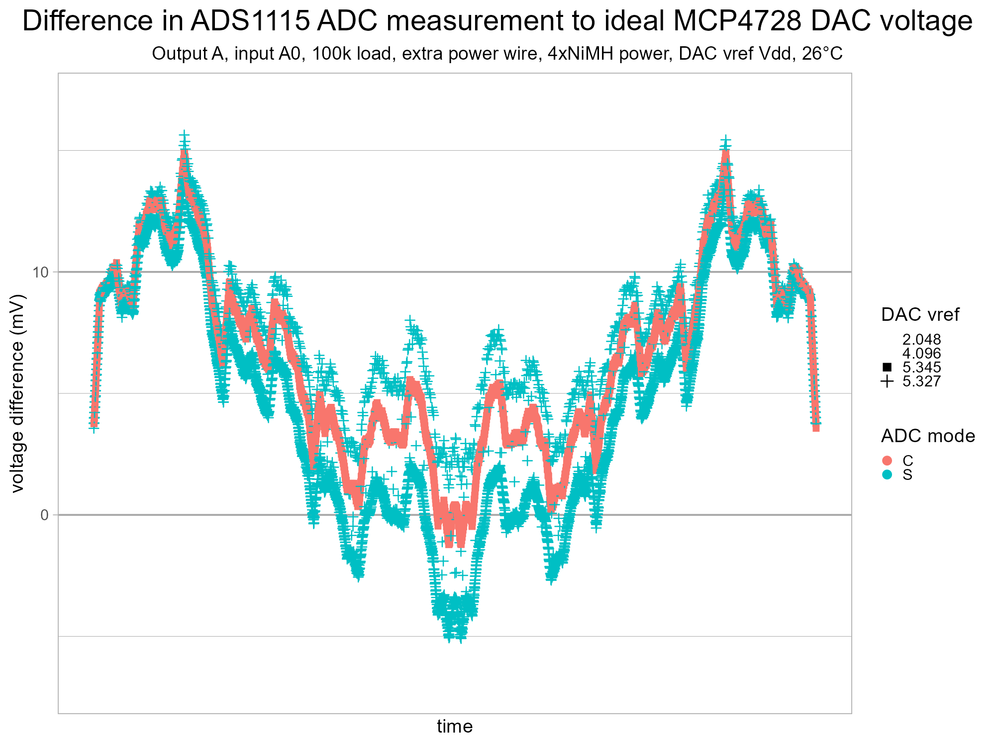
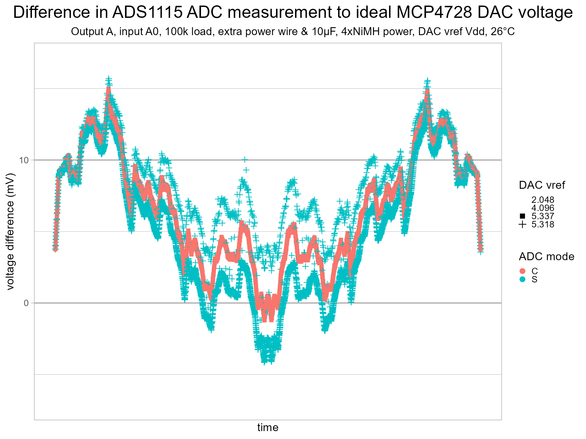
The voltage is in the plots above as the voltage measured by the TI ADS1115 ADC minus the ideal DAC voltage as the testing ramps up from 0 to 4095 and then back down to 0. This voltage should be few millivolts perhaps with a (constant) offset. The small y scale allows a closer examination of the data. The results mostly look good, the DAC has a fairly constant error within the manufacturer's 100-4000 range. The exception is the single-shot test with the DAC's voltage reference set to Vdd. This seems to have two jagged lines close together and a bit of a splatter of measurements between those. The top line looks like the continuous measurements, the lower one looks like its distance from the upper one increases with the voltage.
A few more tests were run with some minor changes to the hardware setup before this issue was fully understood. The plots show differences but no substantial improvement.
- A 100k resistor added as a load for the DAC and a wire from the breadboard power rail to the VCC on terminal block of Grove ADS1115.
- A 10uF electrolytic capacitor added across the breadboard power rails.
The TI ADS1115 datasheet has a description of single-shot mode.
In single-shot mode, the ADC performs one conversion of the input signal upon request, stores the conversion value to an internal conversion register, and then enters a power-down state. This mode is intended to provide significant power savings in systems that only require periodic conversions or when there are long idle periods between conversions.
This implies there's a small but sudden change in load on the power supply when the microcontroller requests a sample value from the ADS1115. This must be very small in terms of current but enough for the AA rechargeable batteries** to dip by about 0.1% and as the DAC's voltage reference is the power supply (aka Vdd) this causes a brief, genuine decrease in the DAC output voltage. There must be a tiny variation in the timing somewhere to cause the mostly alternate measurement of the loaded and less-loaded power supply. This might be due to the variable timing from software running on an interpreter.
A power source with better load regulation should be easily achievable by adding a good quality linear regulator...
** One battery from the six was later found to be seriously degraded. This may have exacerbated the voltage drop due to higher internal resistance.
Power Supply Kit Construction
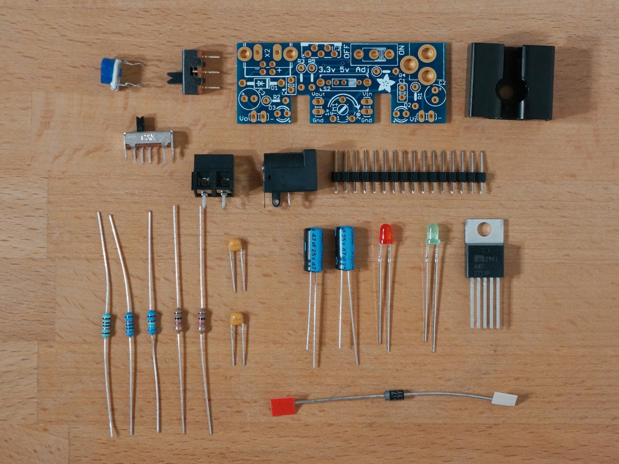
The Adafruit Adjustable breadboard power supply kit is attractive for its selectable output on one output with a choice of 3.3V, 5.0V and an adjustable output. It has a barrel connector making it easy to connect commonly-available AA battery packs.
This kit was assembled and then each voltage was tested. The 3.3V and 5.0V were okay but the adjustable output produced a voltage similar to the 7.5V test input voltage regardless of the potentiometer setting. A visual inspection with a magnifying glass showed one of the small pins on the selector switch had been missed and not soldered. The power supply worked fine after this was soldered. This highlights the importance of
- not rushing the construction,
- careful visual inspection after soldering with a magnifier and
- thorough testing before use to avoid any voltage-related accidents.
Hardware Setup II
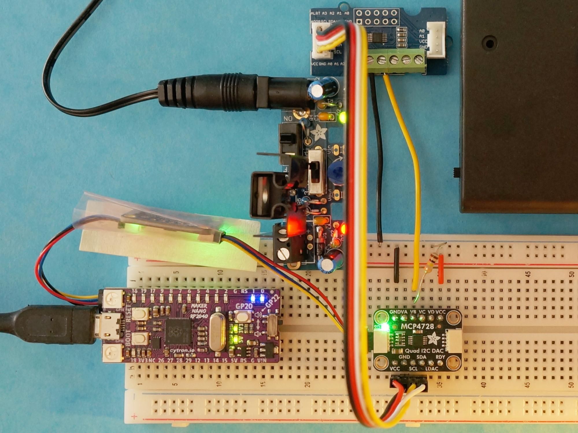
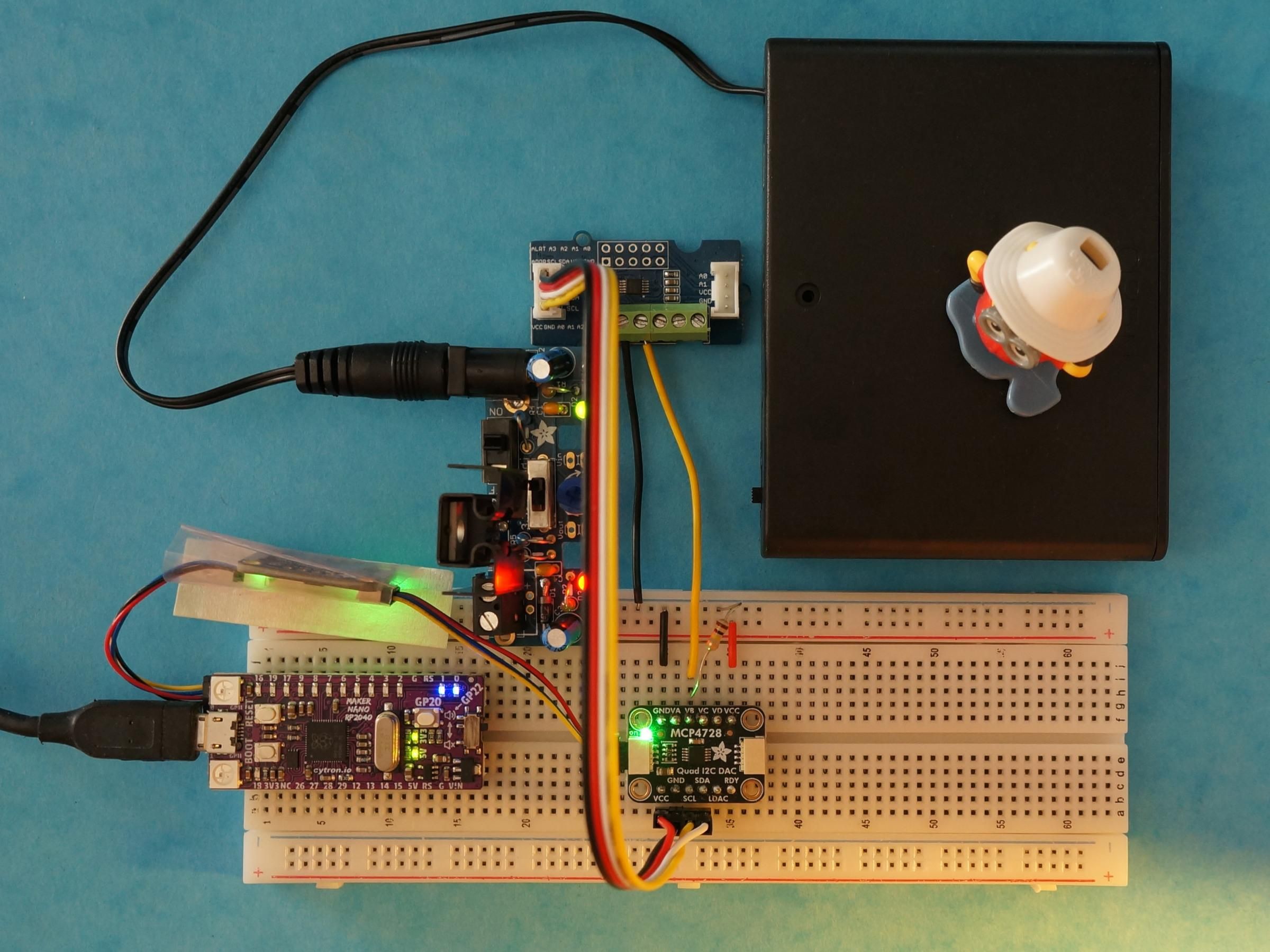
The power to the breadboard rails shown in the photograph above is now provided by the power supply set to about 5.2V with a larger battery pack containing 6 rechargeable (NiMH) batteries. The layout of the components of the breadboard has been maintained meaning the power supply dangles** off one side of the breadboard.
The female Grove cable and jumper wires have been replaced with a single male Grove cable to hopefully improve the quality of the connections.
The extra power wire and electrolytic capacitor have been removed.
** Take care not to short the exposed dangling pair of pins on the breadboard power module - this is the direct power from the battery pack. A spare breadboard could be used to hold these pins safely.
Regulated Battery Power Test Results
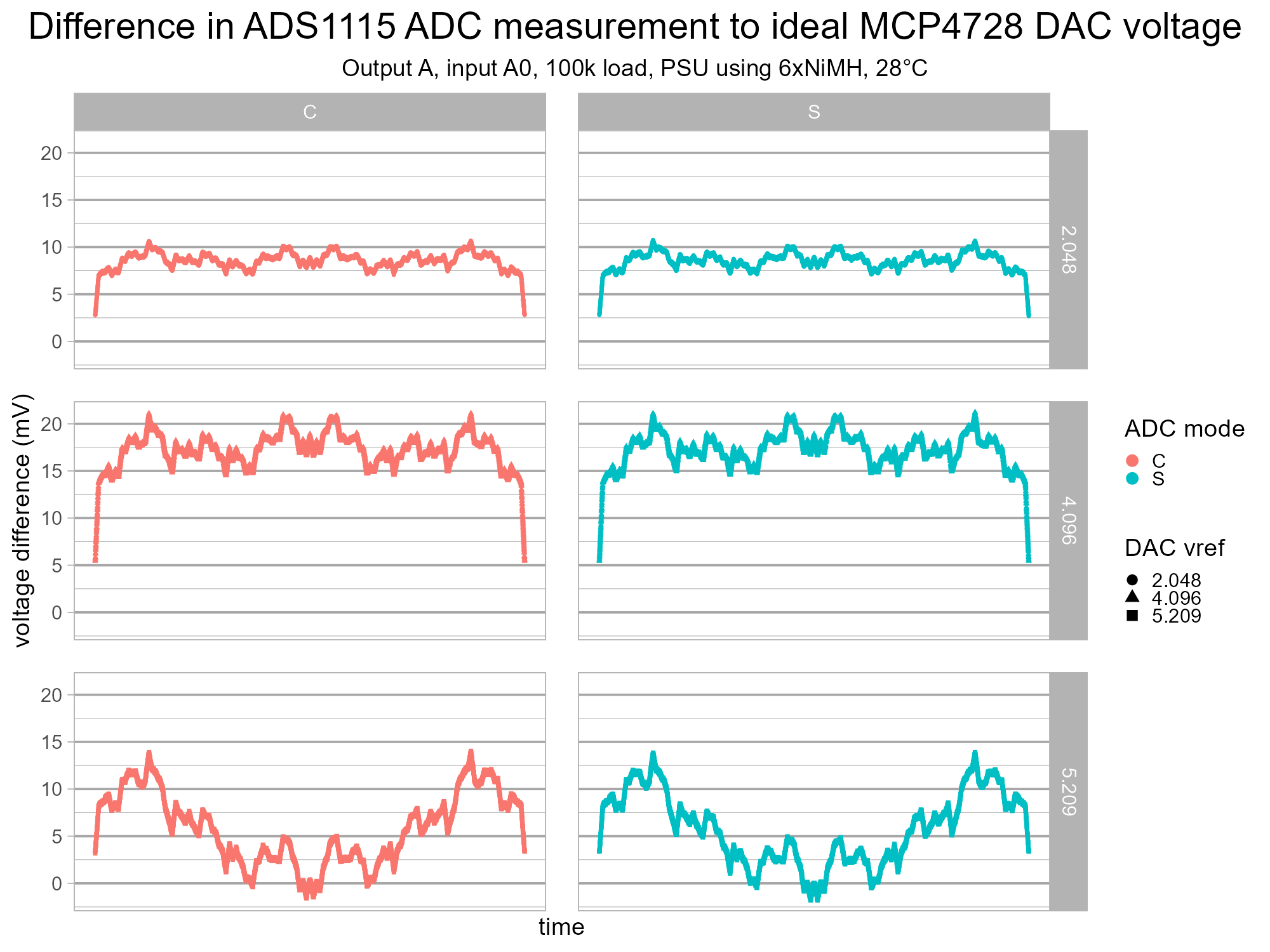
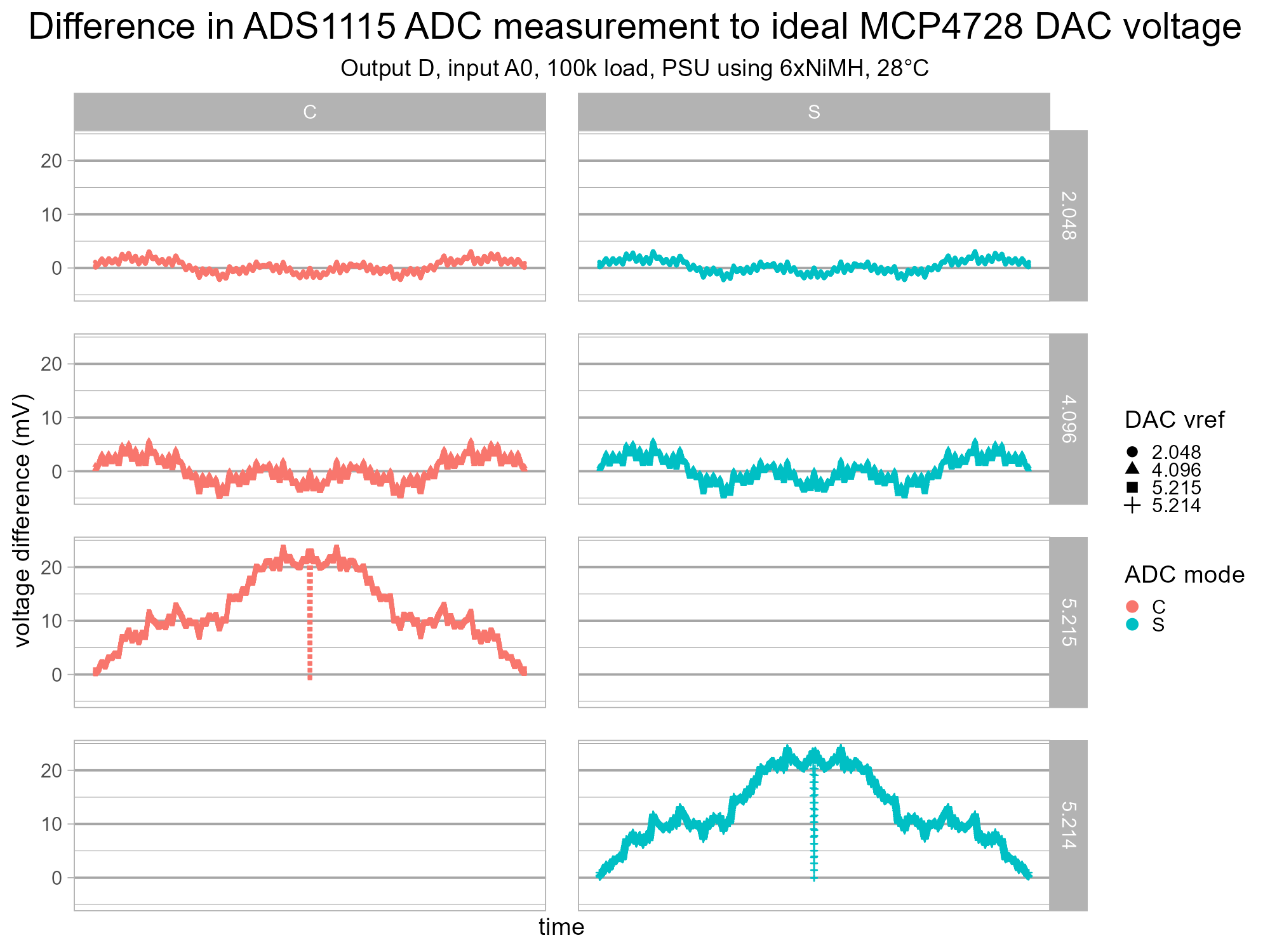
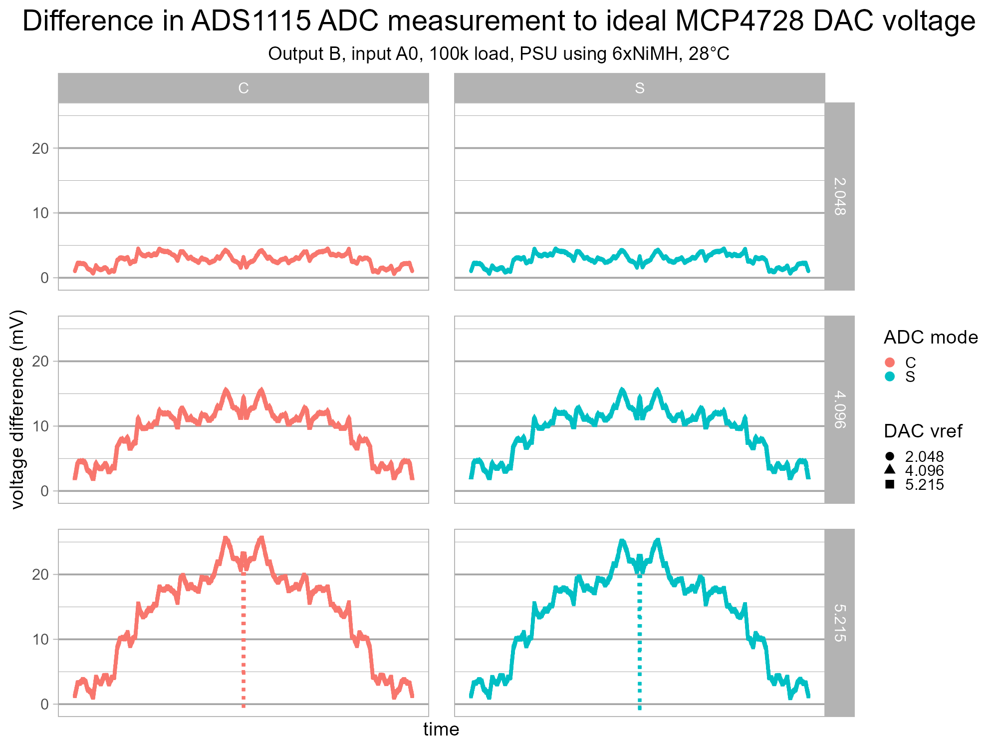
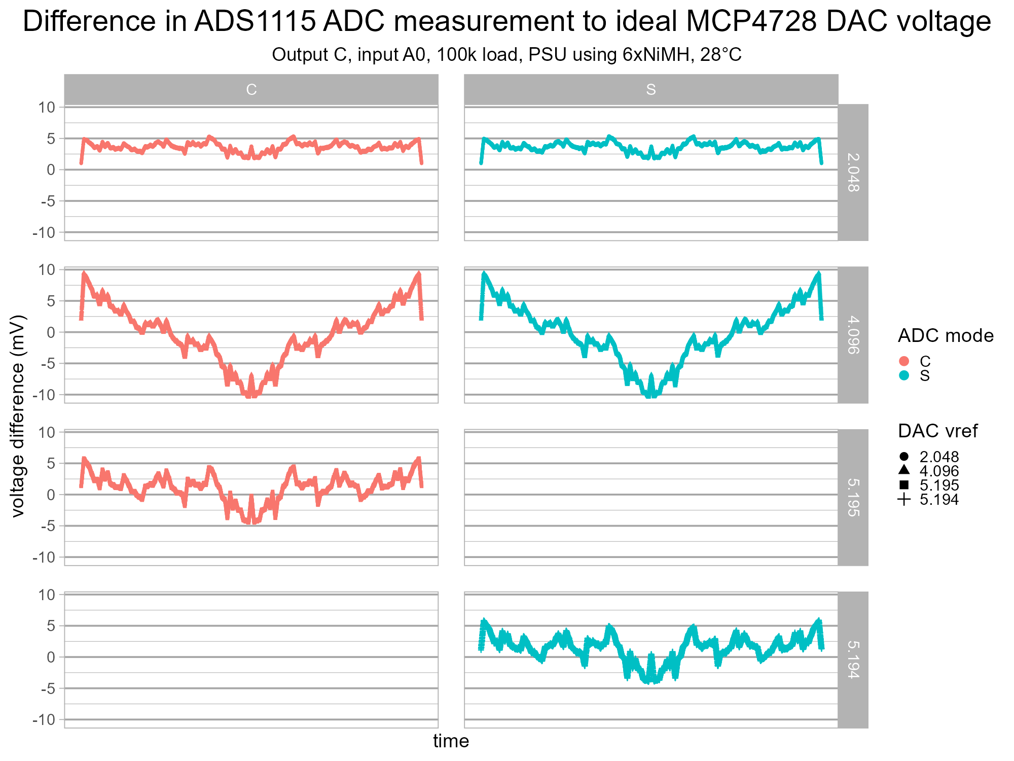
The test was re-run with the new hardware setup and the results showing the single-shot mode are now consistent with the continuous mode. This implies the power supply for the DAC (and ADC) is no longer dipping.
The three other channels on the DAC were tested too. These are independent and produce different error differences across the DAC code range.
The voltage is now more consistent between the single and continuous mode maximum values when the DAC voltage reference is set to Vdd. When it does vary it's only by 1mV for each channel. The channels are either producing slightly different maximum values or the power supply voltage is varying over time a tiny bit.
INL Plots for This MCP4728
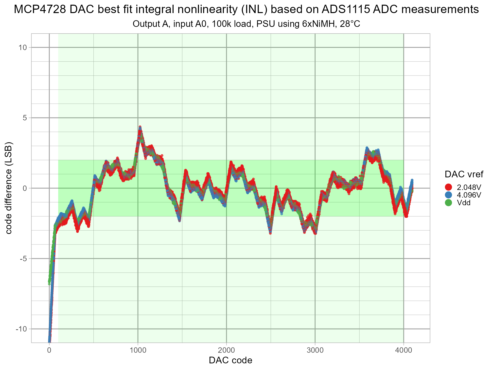
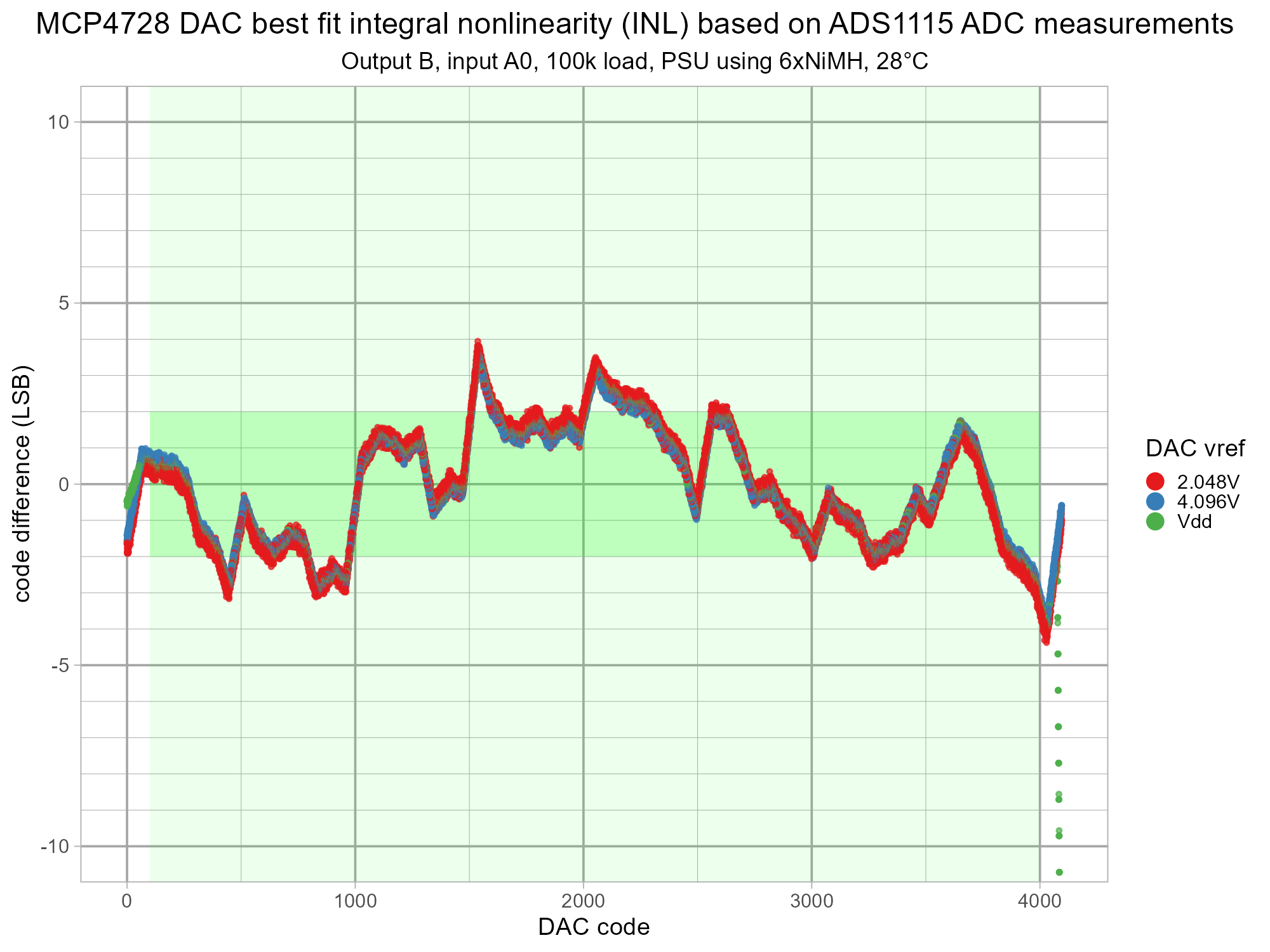
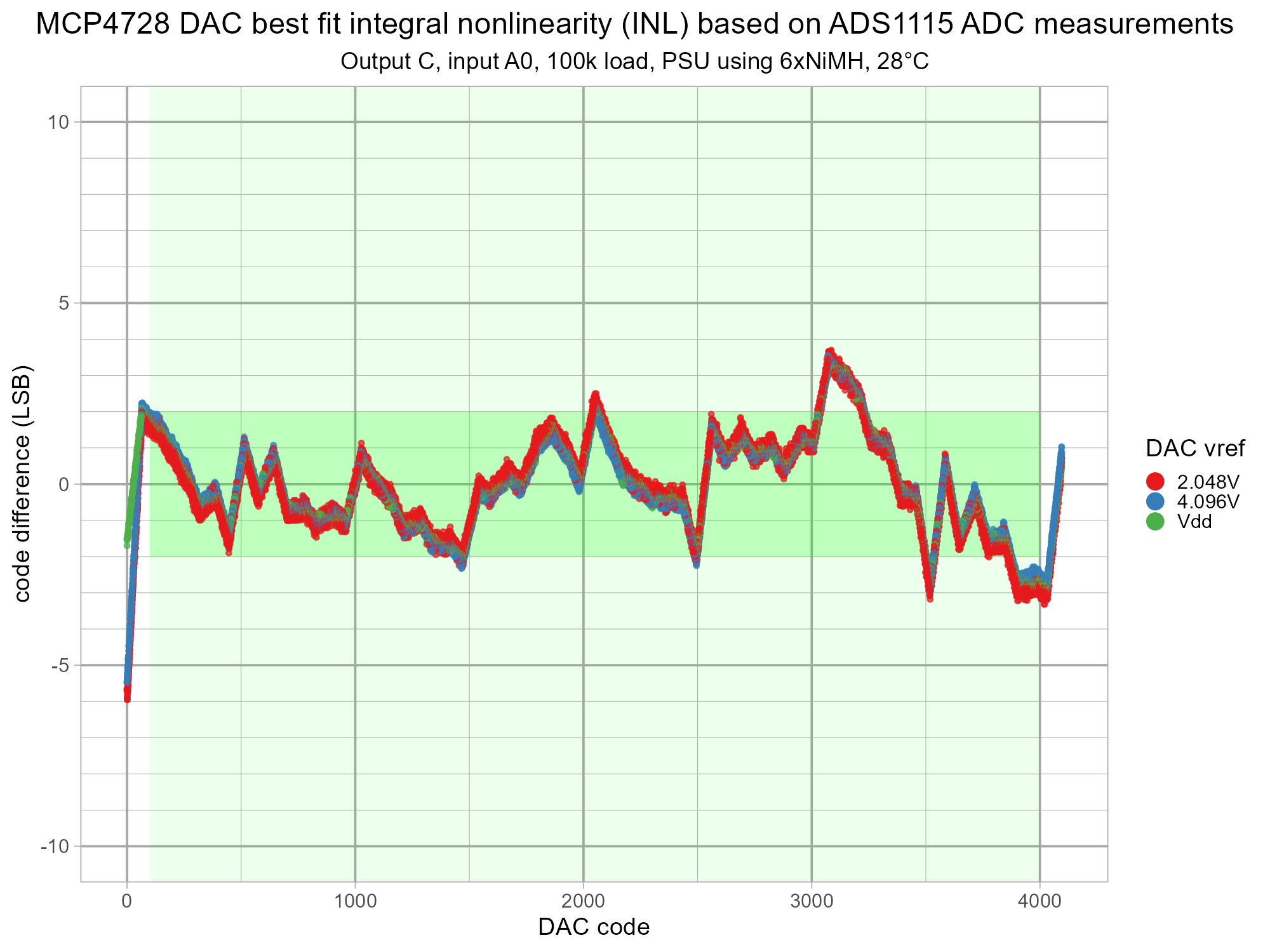
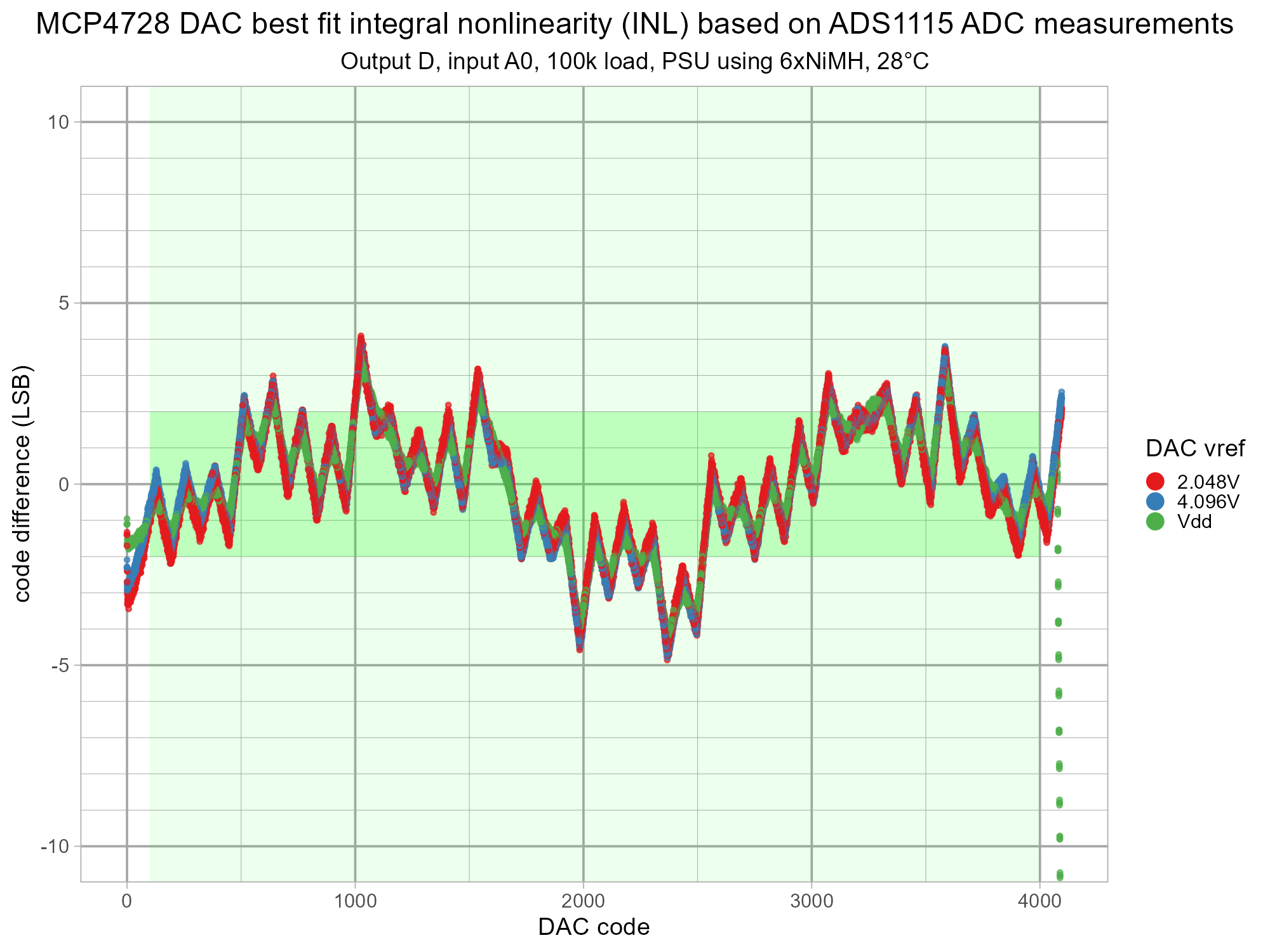
The voltage error in the previous plots is very close to one of the common measurement used in the specification for ADC and DACs, the integral nonlinearity (INL). The only difference is the optional correction of a best fit line and expression as units of the DAC codes, commonly referred to as LSB (least significant bit). The data is shown corrected by a best fit line weighted for the 100-4000 DAC code range. All of the measurements can be amalgamated because they are represented as LSB.
A pale green background shows the 100-4000 range where the MCP4728 has very good linearity. The MCP4728 datasheet cites typical INL as +/- 2 LSB and max +/-13 LSB at "Test code range: 100 - 4000 codes, VREF = VDD, VDD = 5.5V". A more vivid green is used to highlight the +/- 2 LSB area and this makes it more obvious that the majority of the values lie within this region with only a few brief excursions to +/- 4 LSB.
DNL Plots for This MCP4728
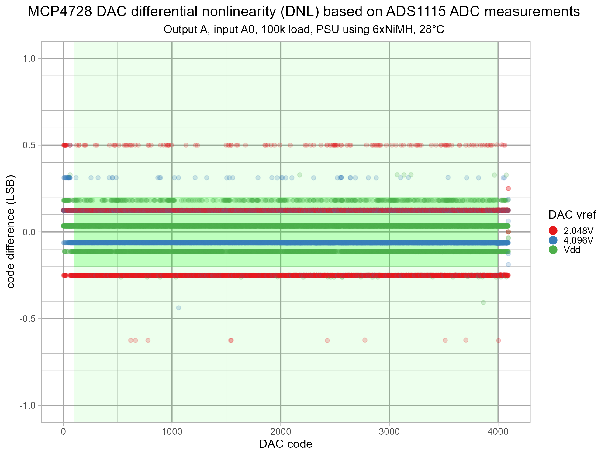
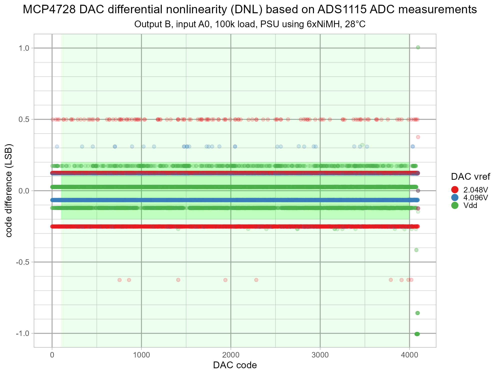
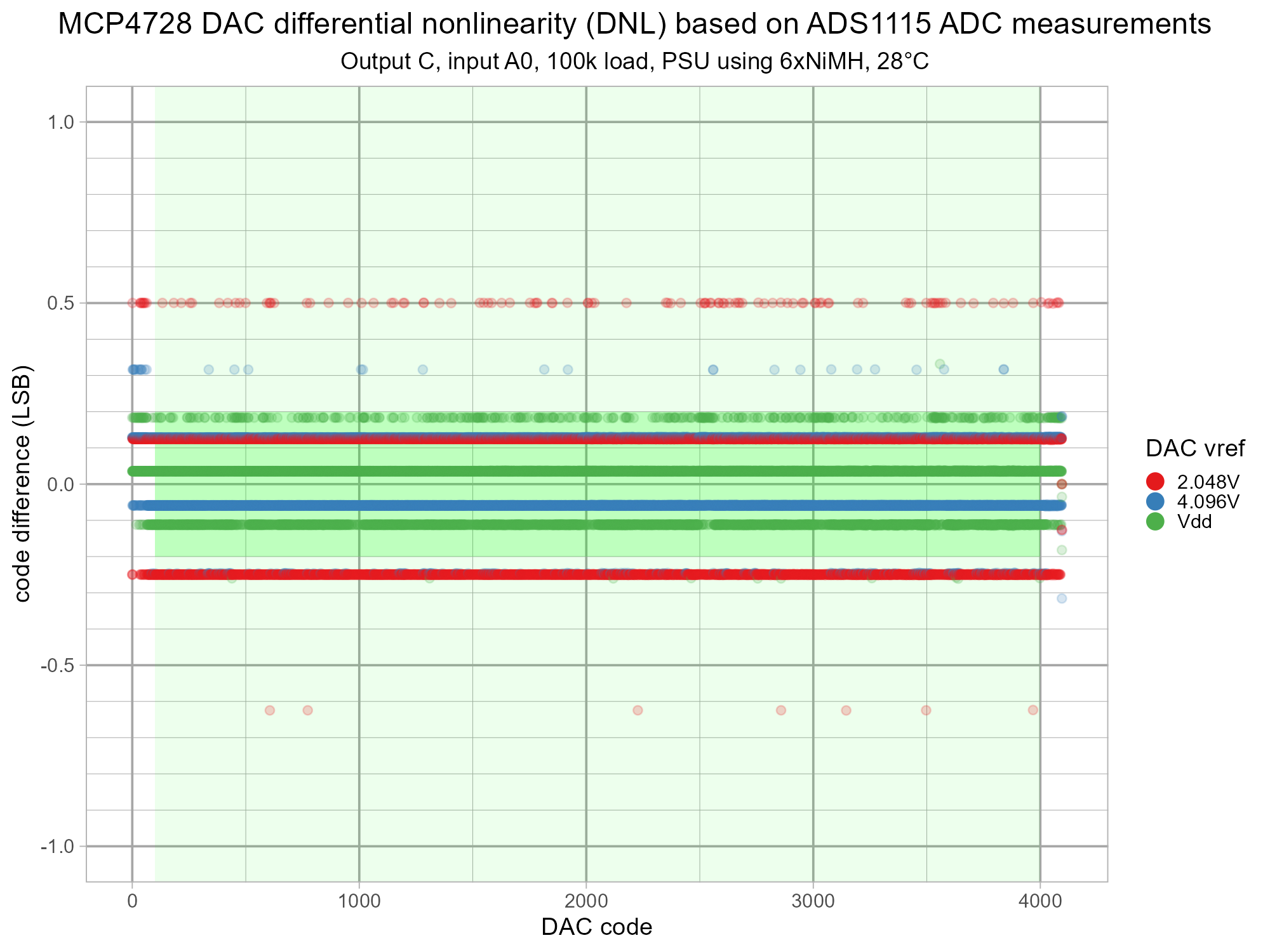
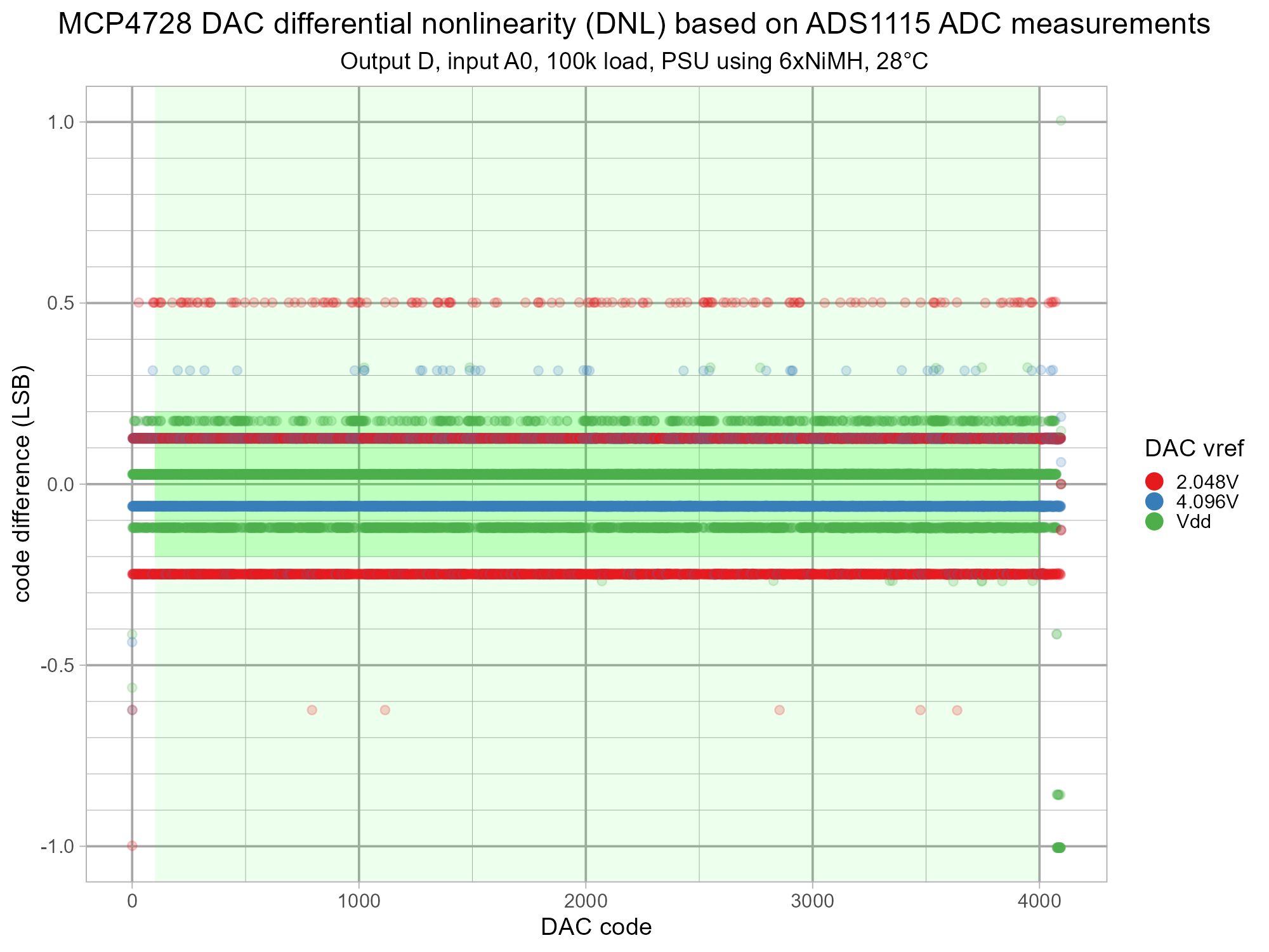
This is the differential linearity (DNL) plot for the four channels. The banding look peculiar until the resolution of the ADC is considered. The TI ADS1115 is a 16bit ADC but this covers a negative range too so there are only 15 bits of resolution in the positive range. When the gain is set to 2/3 the ADC range is +/- 6.144V. This means each ADC LSB equates to 6.144V / 32768 = 0.1875mV. Therefore, the ADS1115 has a fairly limited ability to measure single code increments in the MCP4728 DAC. The calculation of how many ADC LSBs cover each DAC LSB for different voltage references follows.
- 2.048V / 4096 = 0.5mV (2.67 ADC LSB) - shown in red on plot.
- 4.096V / 4096 = 1mV (5.33 ADC LSB) - shown in blue on plot.
- 5.2V / 4096 = 1.2695 mV (6.77 ADC LSB) - shown in green on plot.
This creates the discrete values which are so visually striking in the plots.
The MCP4728 datasheet has typical DNL as +/- 0.2 LSB, min as -0.75 LSB and max as +0.75 LSB at "Test code range: 100 - 4000 codes, VREF = VDD, VDD = 5.5V". A green background is used again to the show the linear range and the typical DNL band. The ADC granularity (quantisation) is affecting the values here but it looks plausible that the vast majority of actual values are within +/- 0.2 LSB.
These y scale of these plots is intentionally limited to +/- 1.0 LSB.
DNL Plots for This MCP4728 - a Different Visualisation
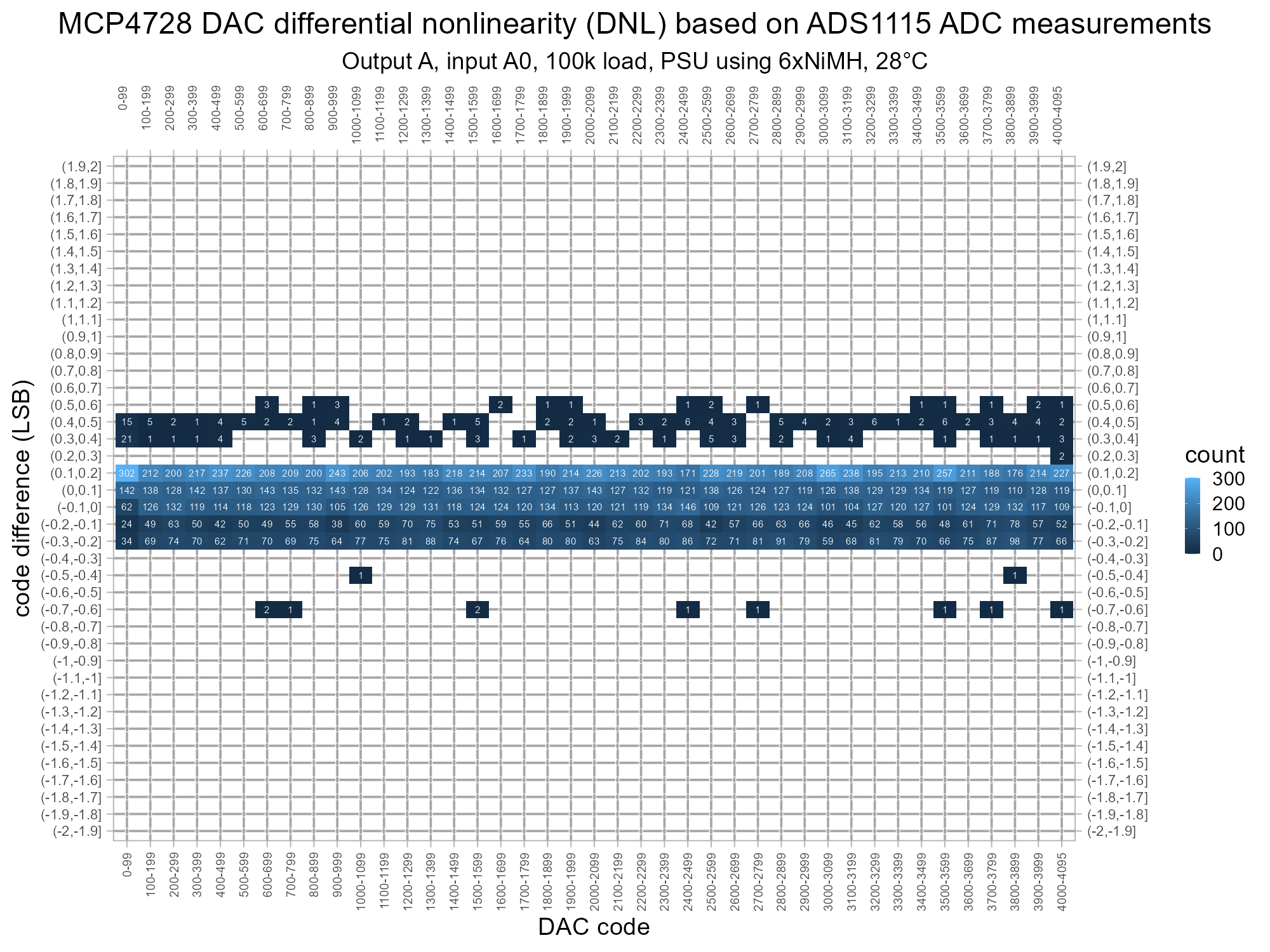
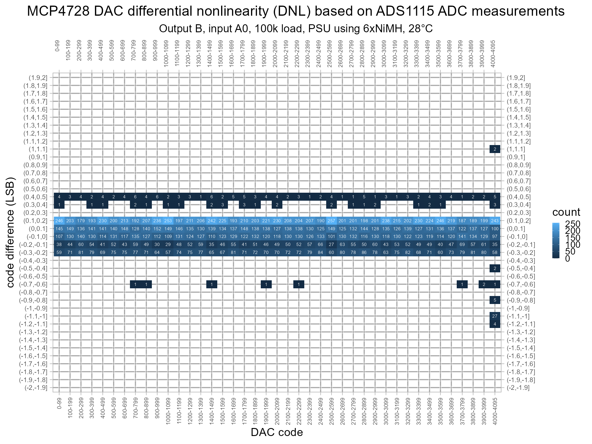
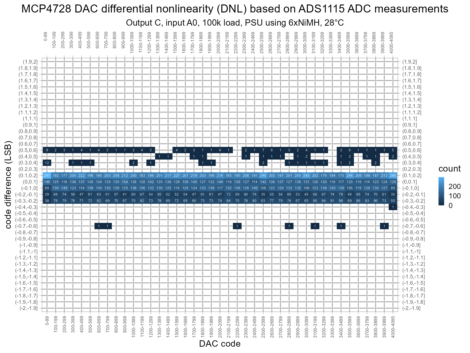
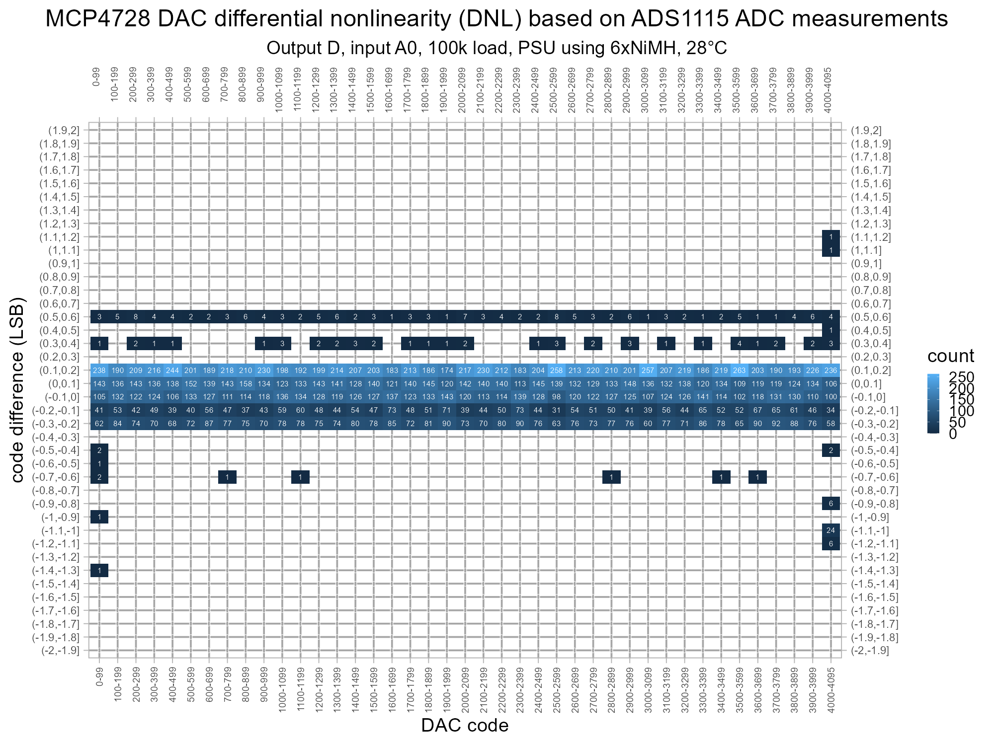
This looks at the differential linearity (DNL) plot for the four channels over +/- 2.0 LSB and uses an annotated heatmap to give more information about where each channel might stray from the datasheet. Buckets without any values aren't plotted to make the deviations more visually obvious.
Most of the values are within the typical +/-0.2LSB as per the datasheet but there's also a lot in the -0.2 to -0.3LSB range - as previously noted this could be due to ADC quantisation. All of the 100-3999 values are within +/- 0.7 LSB as per the datasheet's max/min of +/- 0.75 LSB. Channel B and D do go beyond +/- 1 LSB outside of the 100-3999 range where linearity is acknowledged to be poorer.
Zero Offset and Best Fit Plots for This MCP4728
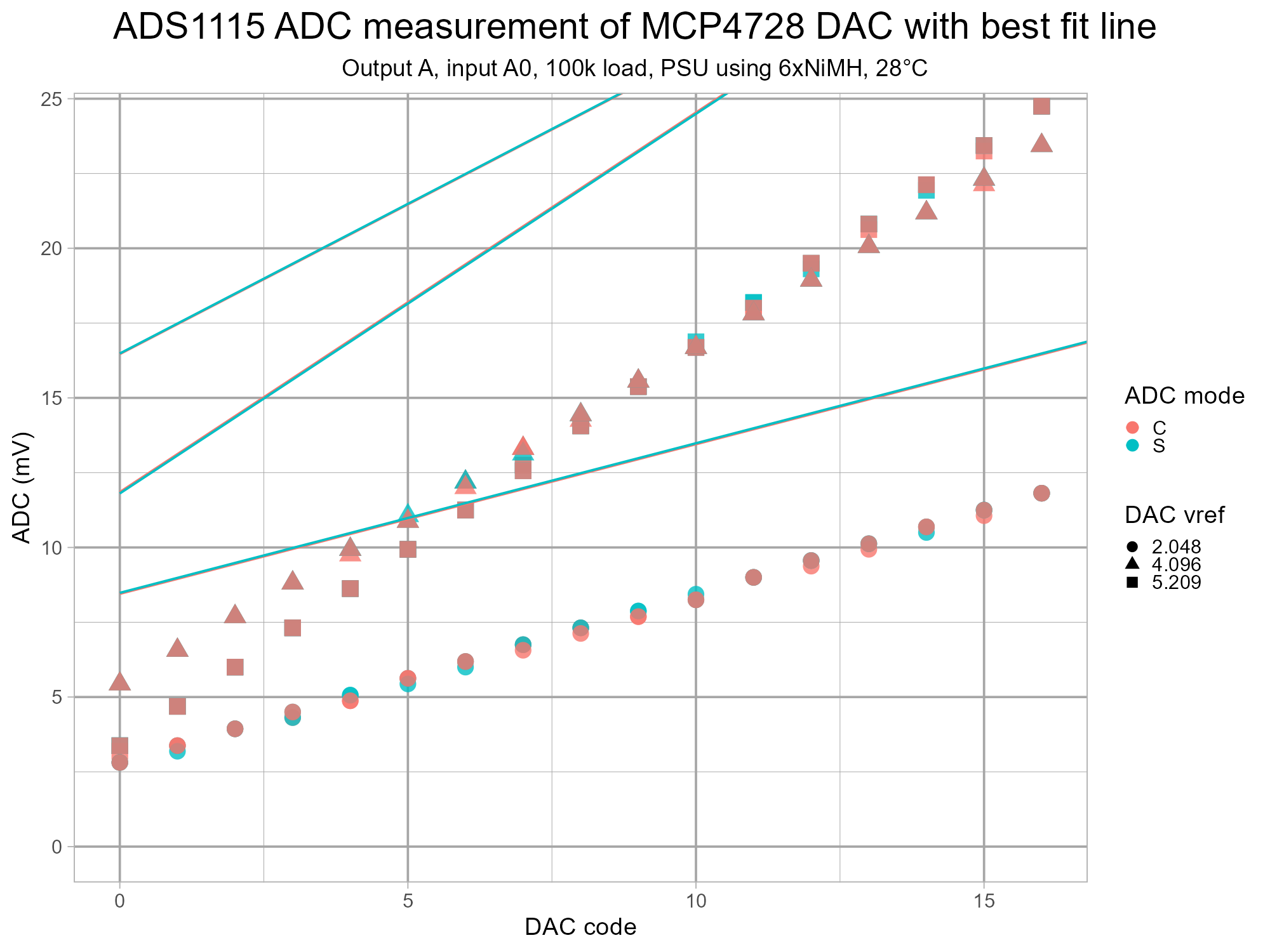
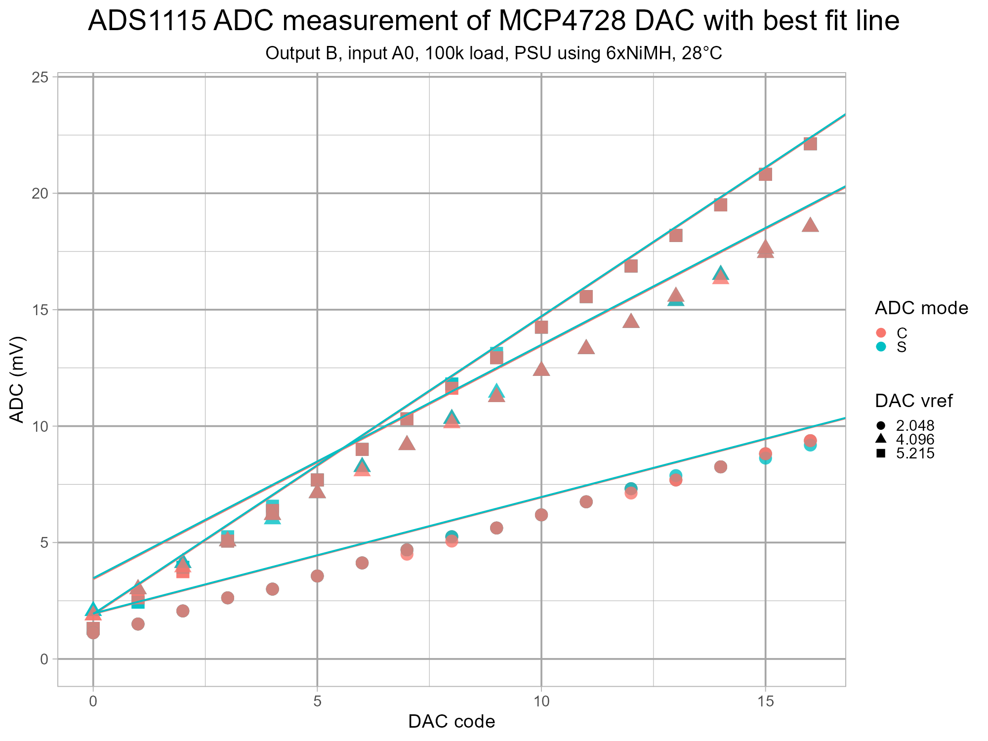
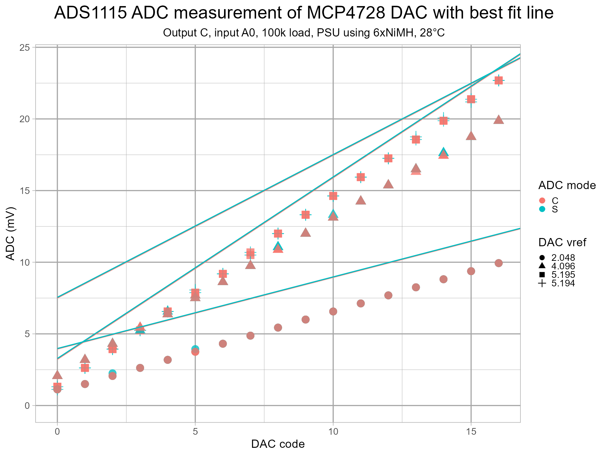
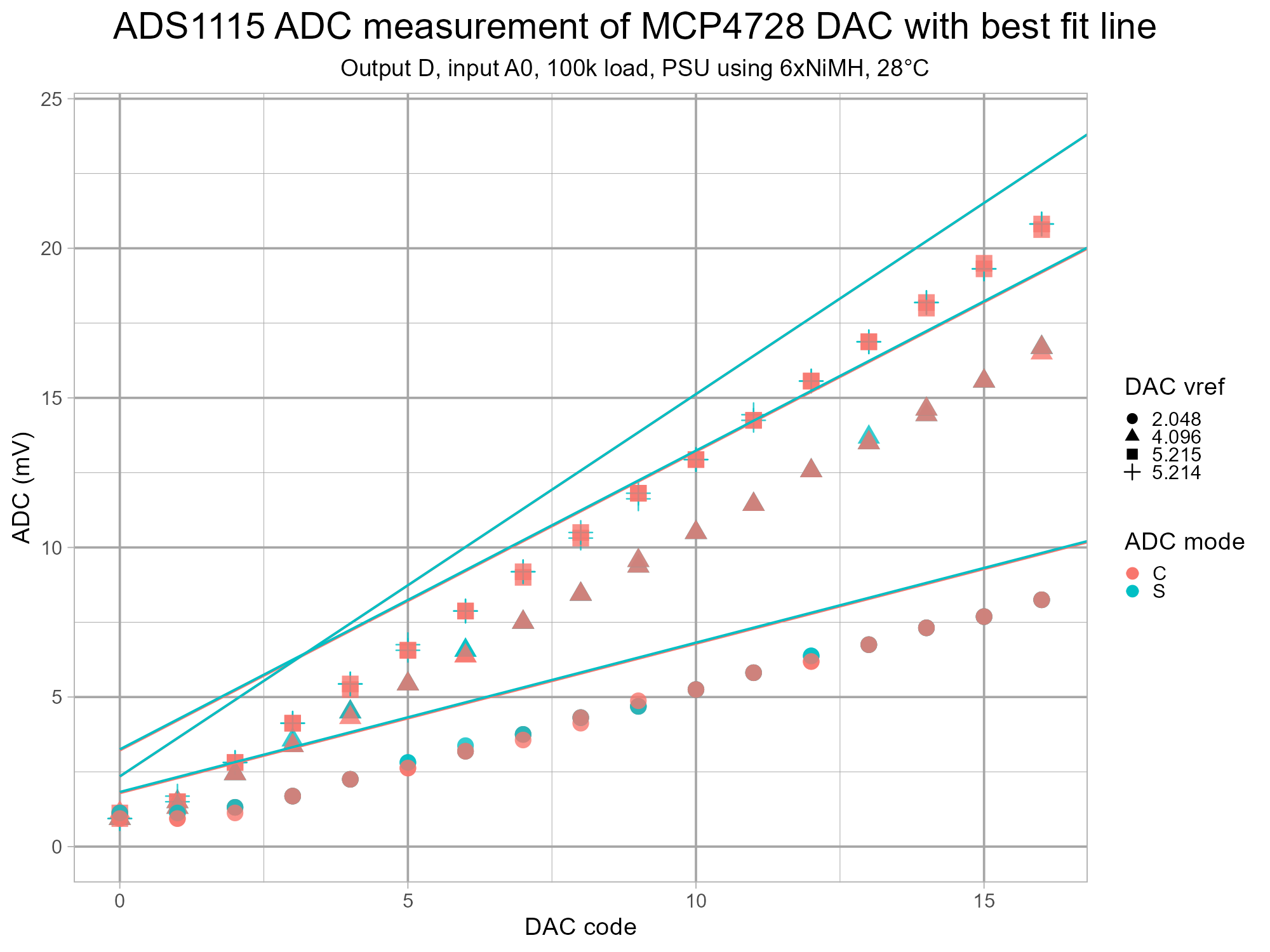
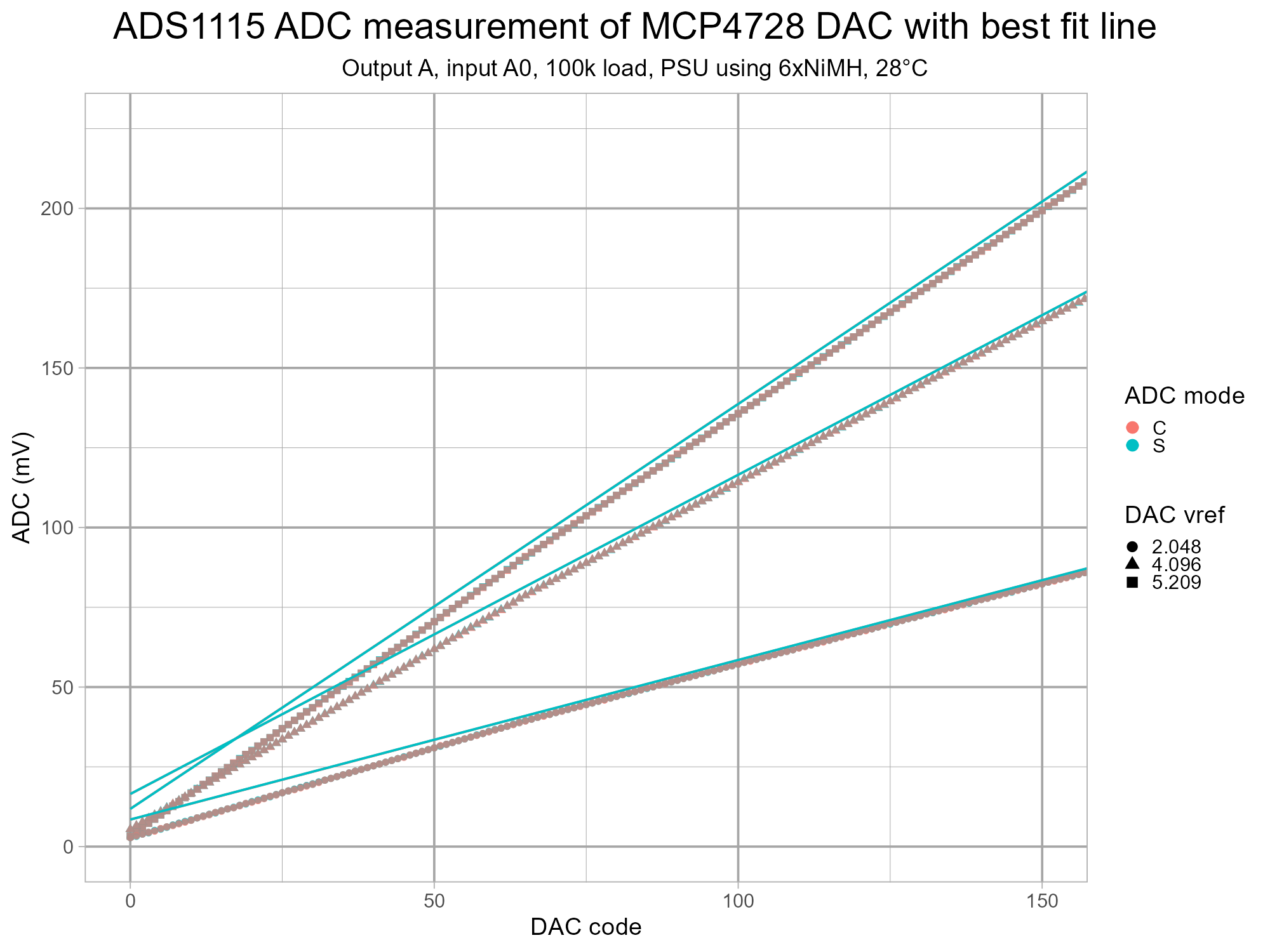
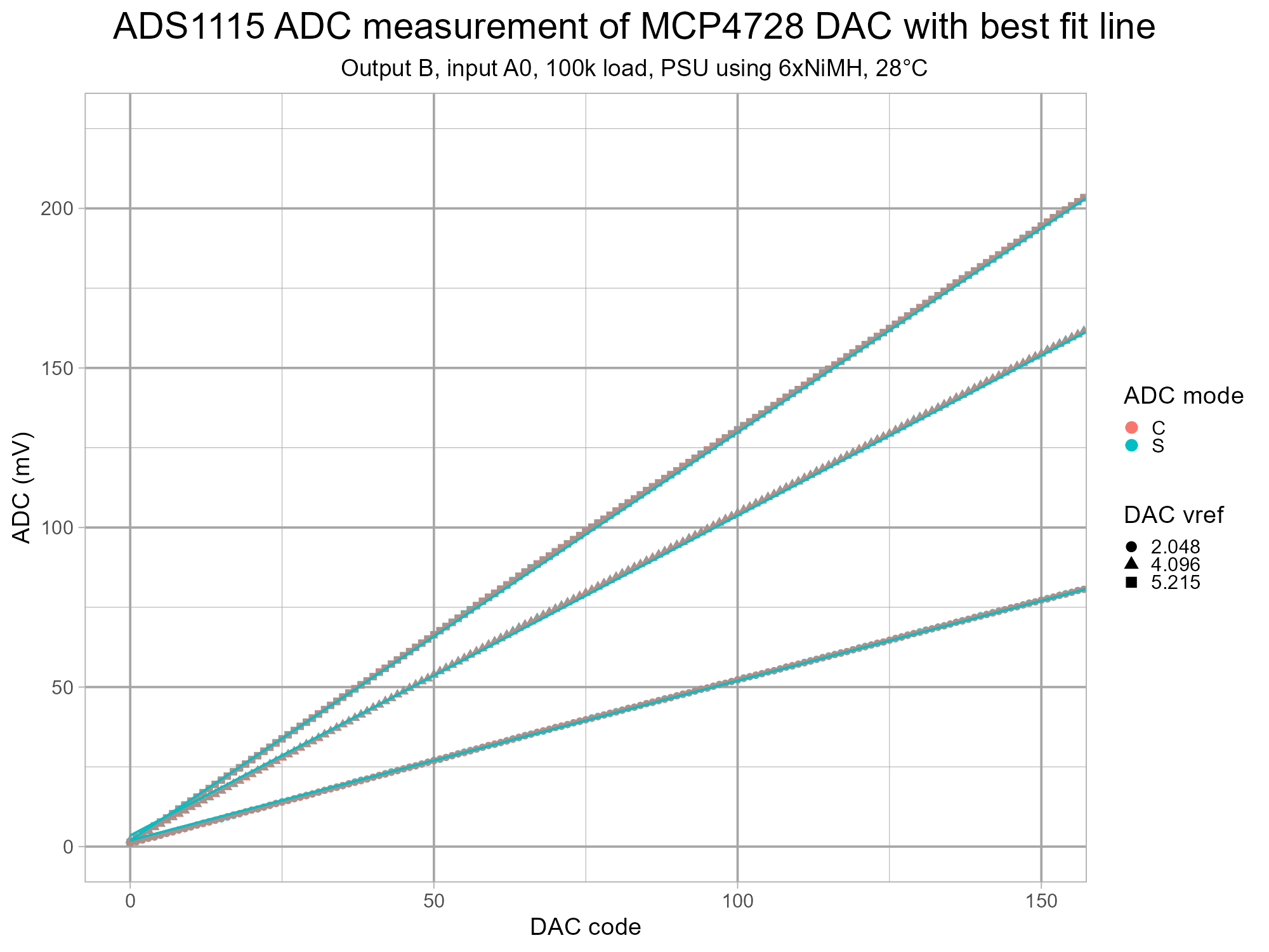
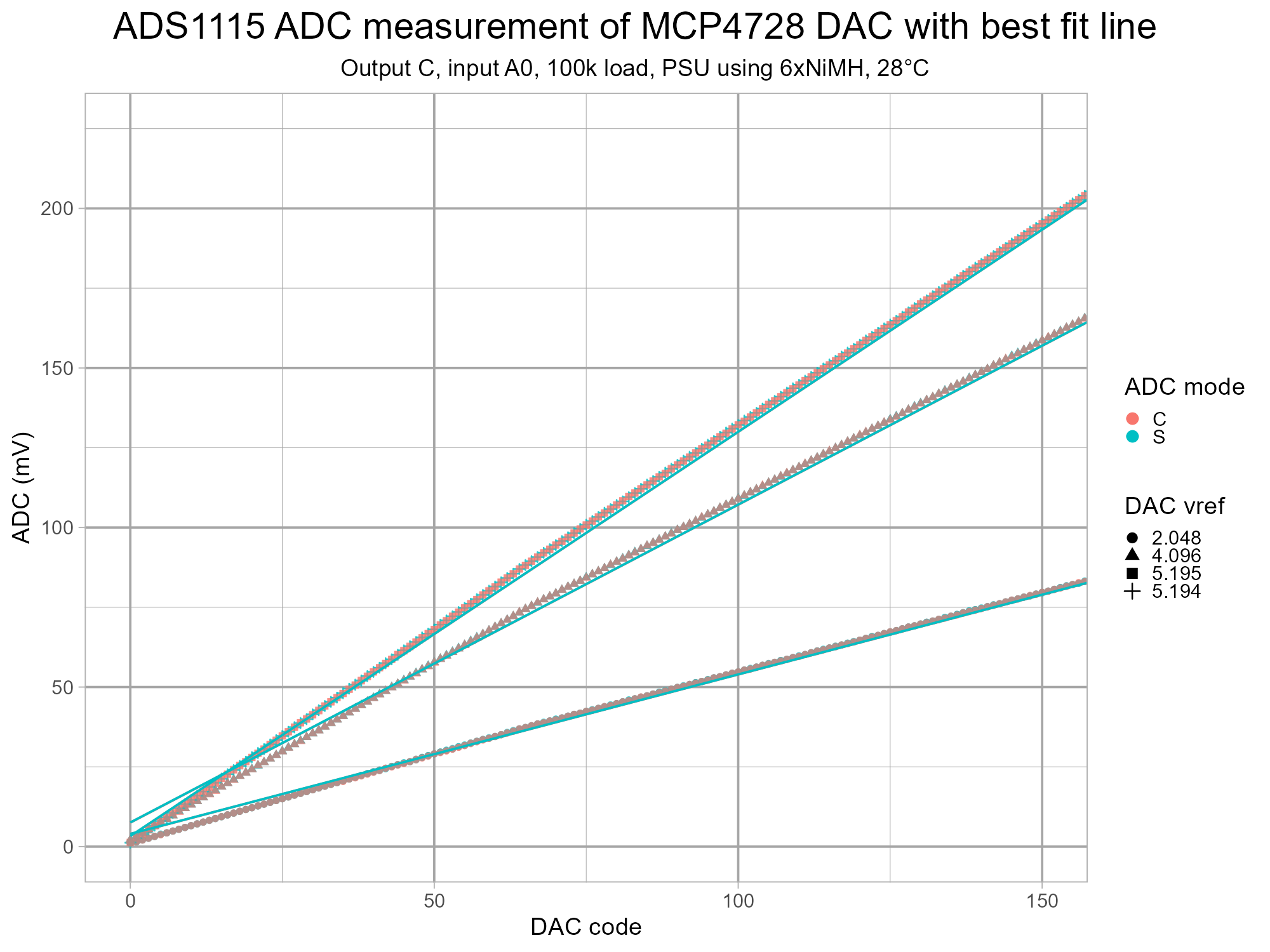
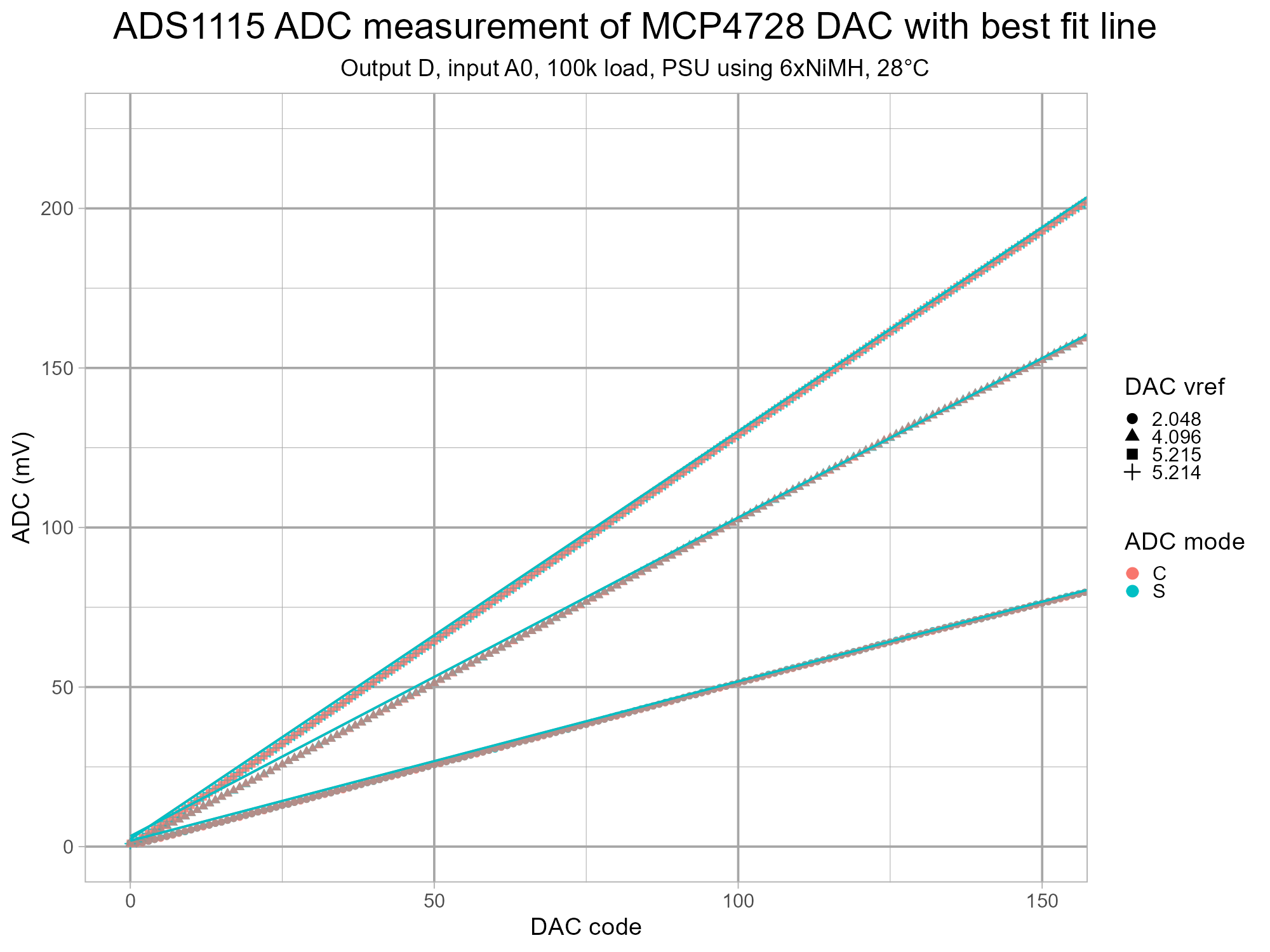
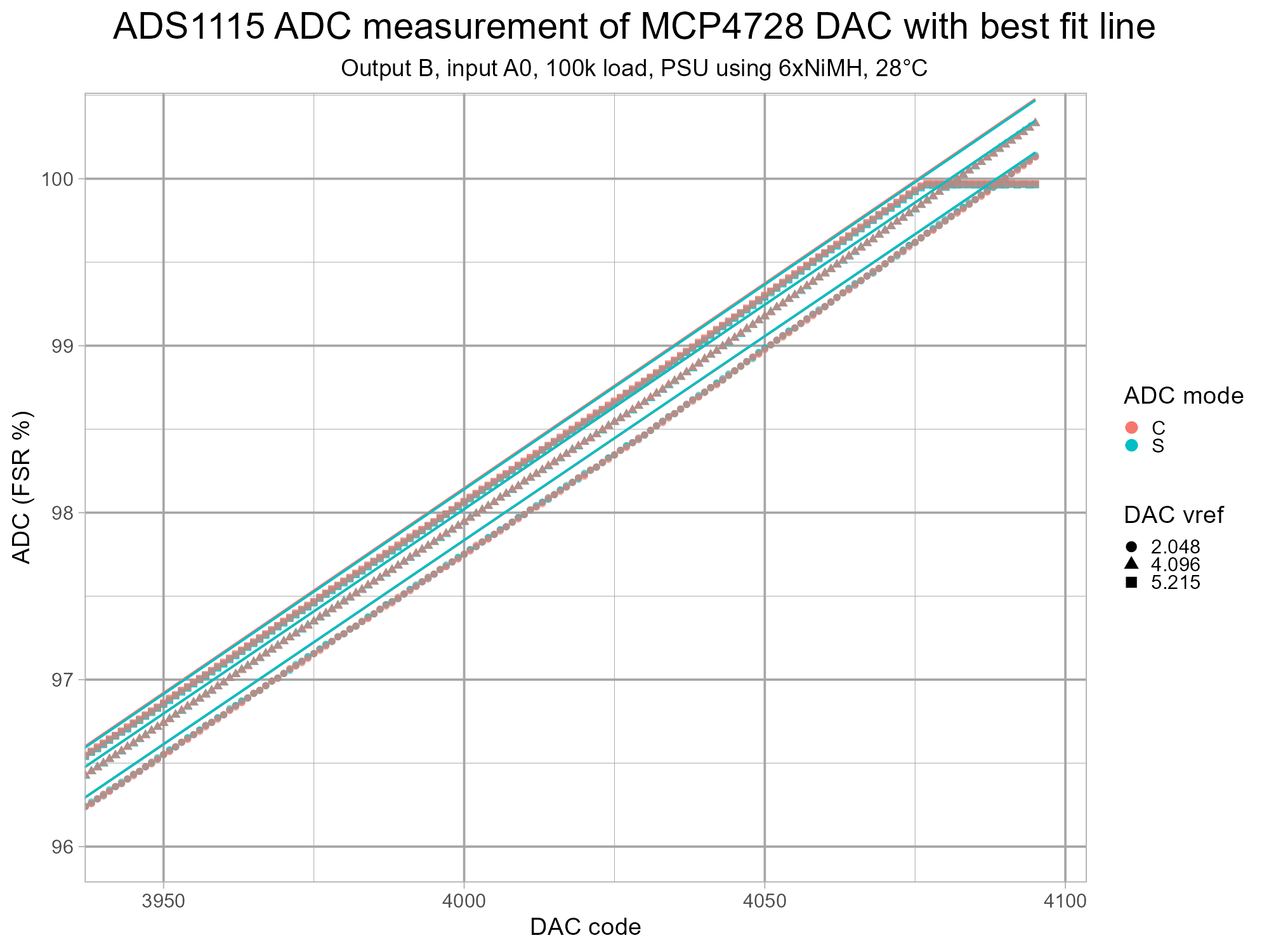
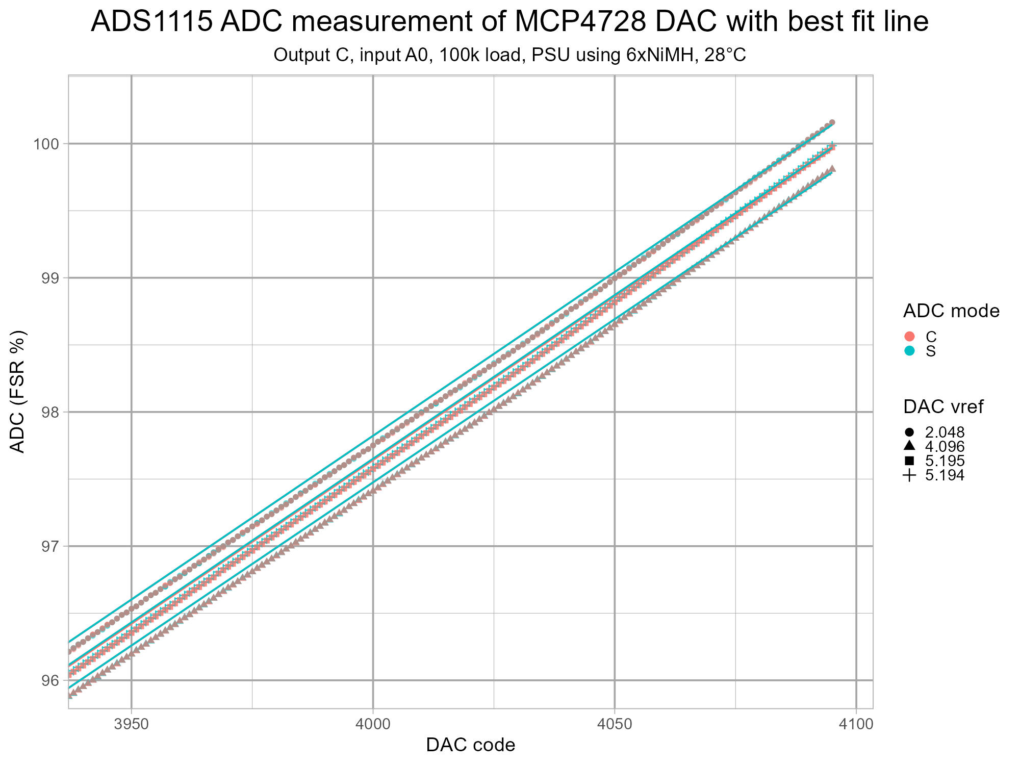
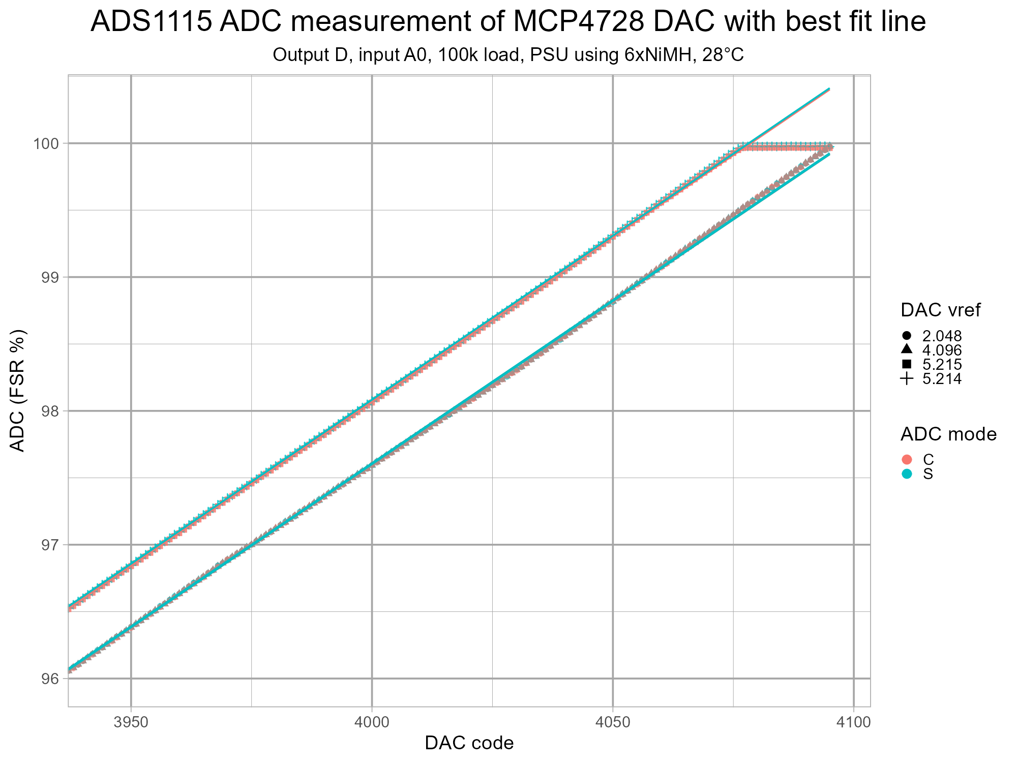
A closer look at the first few DAC codes reveals the output offset from 0V. This varies considerably per channel and is highest for the reference voltage of 4.096V on three channels.
The best fit line weighted for 100-4000 DAC codes isn't well matched with the data at 0 but it's good at 100.
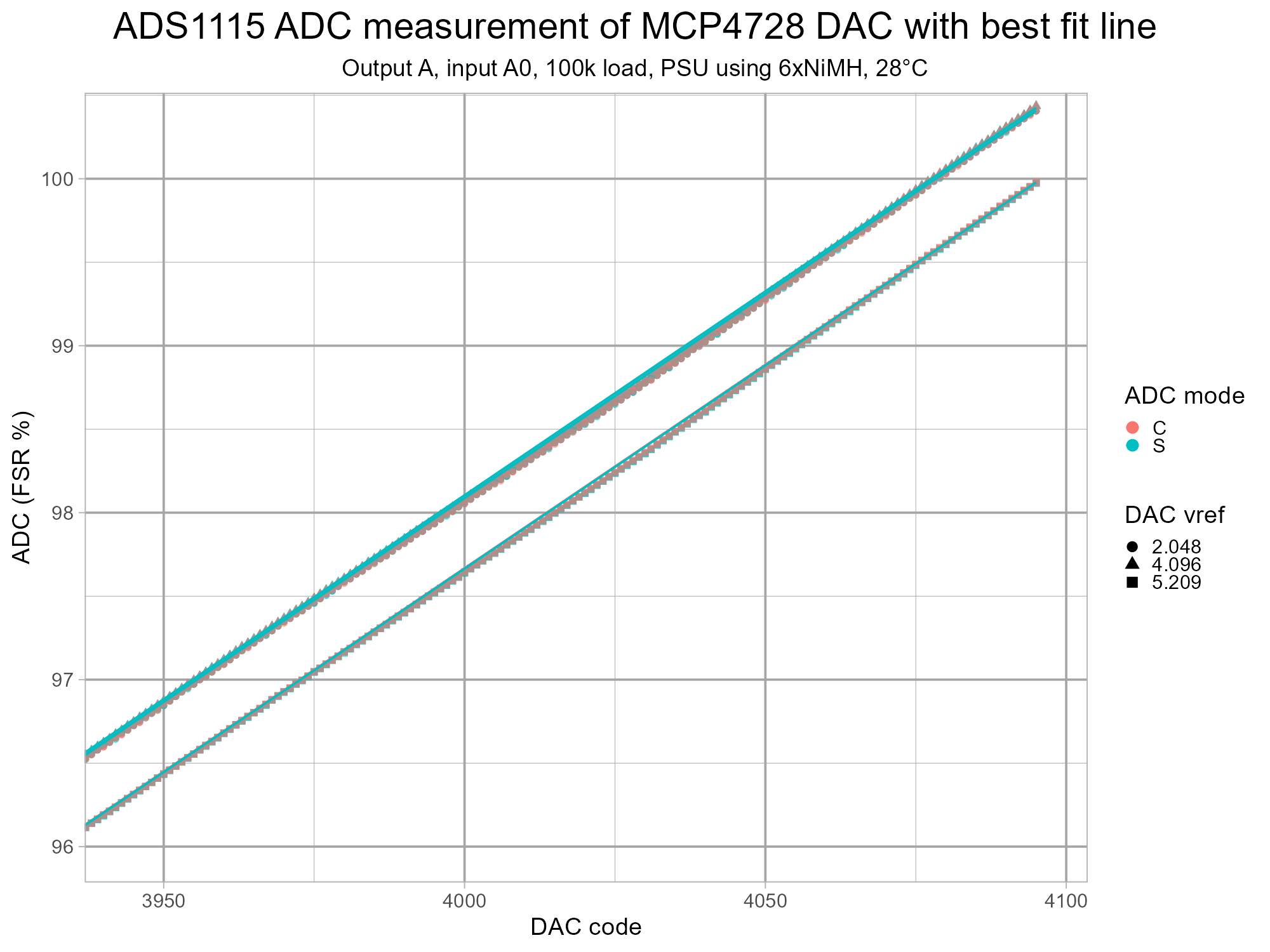
The high end of the DAC codes is shown using the percentage of Full Scale Range (FSR) to normalise the data and allow all of the points to be seen together. Some channels hit a limit and flatten off and this appears to depend on the voltage reference used.
For the internal voltage references, the voltage at DAC code 4095 (not shown on plots) for each channel is listed below.
Going Further


Some ideas for further exploration:
- Run the tests with different output loads.
- Test some more MCP4728 DACs to see if they are consistent.
- Experiment with different sample rates on the ADS1115 to check noise improvement at lower rates.
- Test some MCP4728 from dubious sources to see if there are out of specification devices, i.e. possible counterfeits.
- Find something interesting to test with this new found variable voltage output.
Similar articles/projects/testing:
- Mark Omo's Characterizing the Raspberry Pi Pico ADC
- Andreas Spiess: #340 How good are the ADCs inside Arduinos, ESP8266, and ESP32? And external ADCs (ADS1115) (YouTube)
- Instructables: Microrack Modular Synth: MIDI to CV Using Cytron Maker Nano 2040 and Adafruit MCP4728 DAC With I2C Isolation
- Instructables: RP2350 GPIO Input Leakage Current Measurement on Pi Pico 2 W Using Kitronik Inventor's Kit for Raspberry Pi Pico - this wasn't intended to look at the RP2040 ADC DNL issues but does end up showing them.
- Instructables: An Imperfect Comparison of Arduino Analogue and Digital Inputs: UNO R3, Leonardo, UNO R4 Minima and UNO R4 WiFi
- Playduino: ADC accuracy comparison (YouTube) - testing a genuine Arduino UNO R2 (not a typo, very similar to R3), an UNO R4 Minima, an ESP32 board and a Pi Pico using the output from an external DAC. An unbranded ADS1115 board is also shown for a comparison but has some errors probably related to lack of flow control.
- Adafruit Forums: Feather ADC comparison including 2.6V limited ESP32-S2 - a basic comparison of the ADCs in the RP2040, ESP32-S2, ESP32, ATMega328p, nRF52840, SAMD21.
- Stargirl Flowers: Getting the most out of the SAM D21's ADC
- Joerg Vollrath: R2R DAC ramp measurement with INl, DNL (YouTube) - measuring a home-made, simple R-2R 4bit DAC.
Further reading:
- Texas Instruments: Precision DAC essentials (YouTube)
- Texas Instruments: Application Note SLAA013: Understanding Data Converters (pdf)
- Microchip MCP4728 datasheet (pdf) - terminology section is detailed and helpful.
- Analog Devices
- The Data Conversion Handbook, 2005 - chapter 5 (pdf) covers ADCs and DACs.
- INL/DNL Measurements for High-Speed Analog-to-Digital Converters (ADCs)
- Adafruit Industries: Collin's Lab: Powerful Battery Usage with Ladyada (YouTube)
- Vocademy - Electronics Technology: Batteries (YouTube)
The images above were generated with MagicStudio and Grok with the prompt: "Can you generate a 4:3 cinematic image of a person doing some precision testing of a digital-to-analogue converter? The person needs to look like the star of an action film wearing a thin bandana around their forehead featuring the letters ADC and DAC in the fabric."