MICROMOUSE (Maze_Runner)
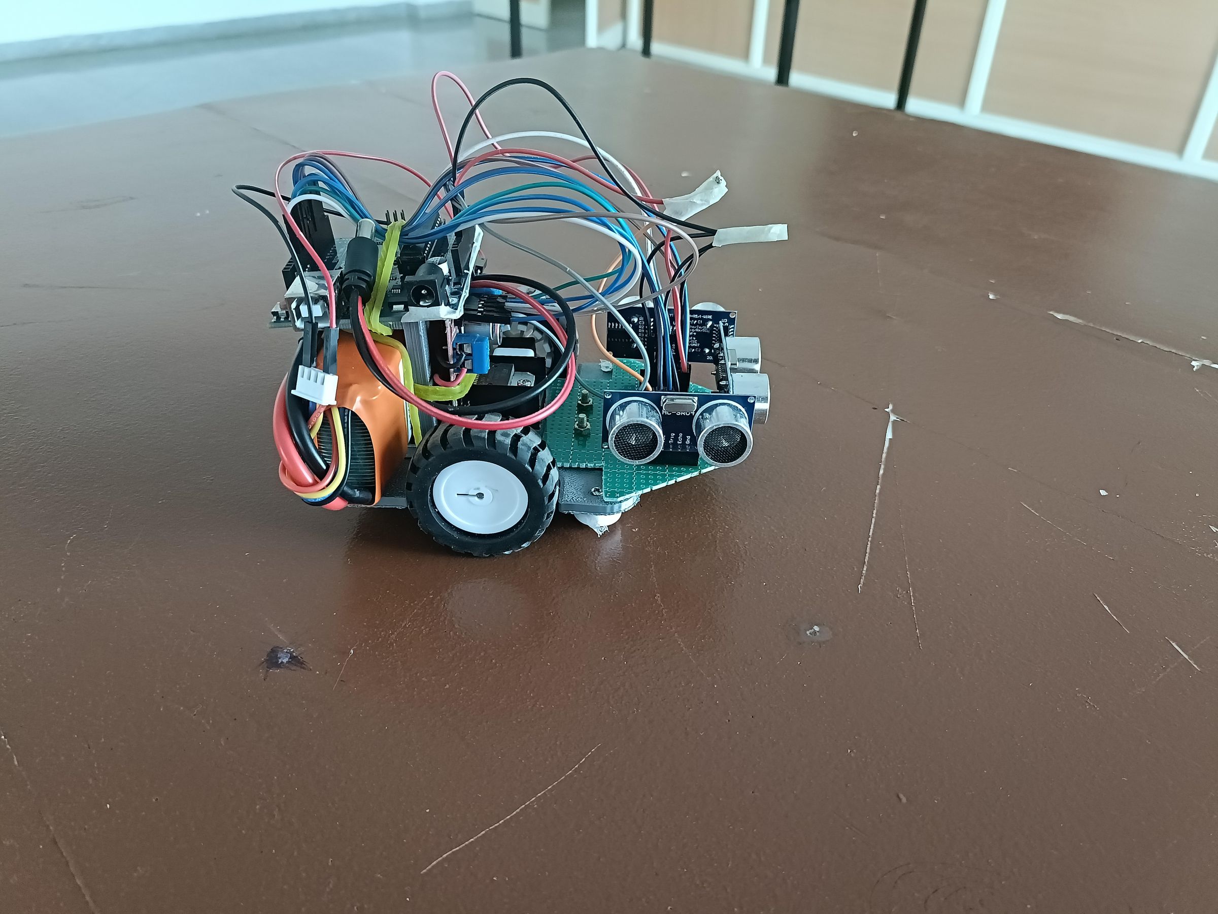
A Micromouse is a small autonomous robot that solves a maze entirely on its own. It uses sensors to detect walls, decides where to move next, and keeps driving until it reaches the goal. This project is ideal for learning robotics because it combines mechanical design, electronics, and programming in one complete build.
This guide walks you through building the Maze_Runner micromouse from scratch — from printing and assembling the chassis, to wiring the electronics, uploading the code, and tuning the robot to navigate a real maze reliably.
What This Robot Does
The robot starts in a known start cell inside an unknown maze. It does not know the layout in advance, so it depends entirely on sensor readings and movement rules. At each decision point it checks: is there a wall in front, on the left, or on the right? Based on that information it decides to move straight, turn left, turn right, or turn around.
How a Maze Solver Thinks
A maze-solving robot works like a decision-making machine. It does not guess the full maze at once. Instead, it reads the current situation, chooses the best allowed move, and repeats the process at the next cell. This is why maze solvers are built using a state-based design — the robot can be in different modes such as waiting, exploring, mapping, searching for the shortest path, or running at full speed after learning the maze.
Main Maze-Solving Algorithms
1. Left-Hand Rule (Used in this build)
The simplest method for beginners. The robot always tries to keep its left side touching a wall:
- If the left path is open → turn left and move forward
- Else if the front path is open → move forward
- Else if the right path is open → turn right and move forward
- Else → turn around (U-turn)
2. Right-Hand Rule
The same logic reversed — keep the right side touching a wall. Both wall-following methods are reliable for simply-connected mazes.
3. Flood Fill (Competition-level)
Every cell in the maze is assigned a distance value. The goal cells start at 0, and values increase outward. The robot always moves toward the cell with the smallest value, finding an efficient route through the maze.
4. DFS and BFS
Depth First Search (DFS): Explores as far as possible before backtracking. Good for exploration but may not find the shortest route.
Breadth First Search (BFS): Explores nearby cells first. Strong for finding the shortest path after the maze has been fully mapped.
State Machine Design
A well-designed maze solver follows a state machine. The Maze_Runner uses these states:
State
What the Robot Does
IDLE - Waits for the start signal (button press or power-on)
EXPLORE - Follows the left-hand rule, checking walls at each cell
MAP_MAZE - Stores wall information in memory as it travels
FIND_SHORTEST_PATH - Calculates the most efficient route using BFS/Flood Fill
FAST_RUN - Executes the calculated shortest path at higher speed
FINISHED - Stops at the goal cell and signals completion.
Supplies
Parts List & Tools
Parts List & Tools
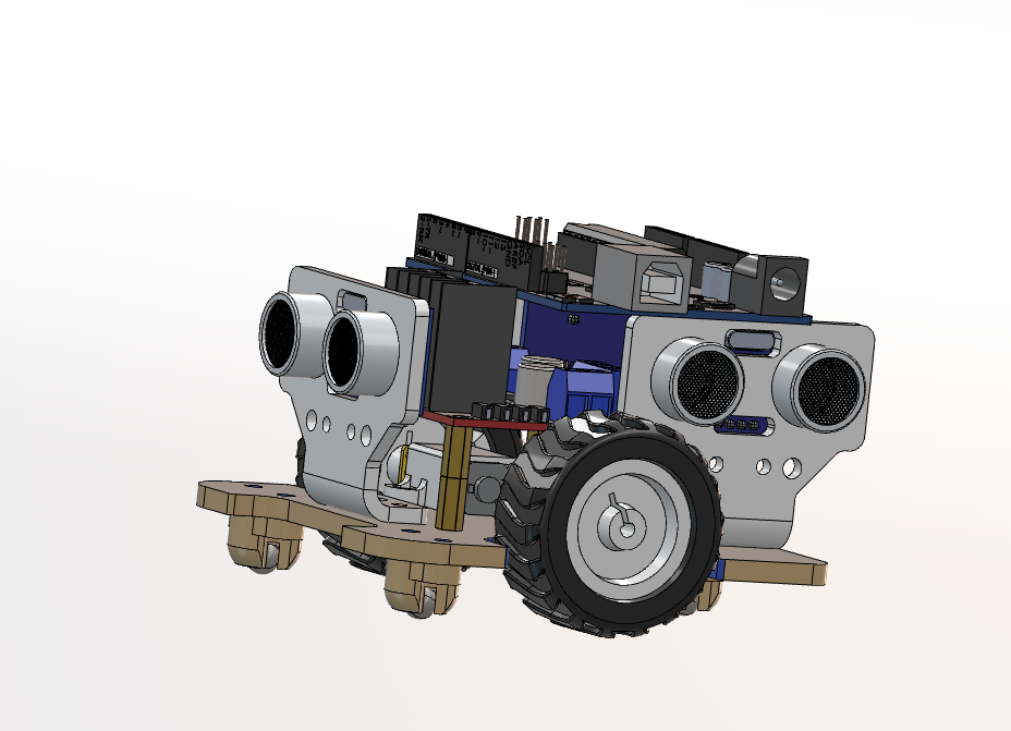
Electronics
Component
Arduino Uno / Nano - 1 - Uno recommended for beginners
L298N Motor Driver Module - 1 -Standard dual H-bridge module
N20 Gear Motors (6V, 100–200 RPM) - 2 - Left and right drive motors
HC-SR04 Ultrasonic Sensor - 3 - Left, Front, Right wall detection
9V Battery + clip (logic power) - 1 - Powers Arduino + L298N logic
AA Battery pack (4×AA = 6V, motor power) or lipo battery of 12v - 1 - Powers motors via L298N
Jumper wires (male-to-male, male-to-female) - 30+(Various lengths)
Mechanical / Chassis
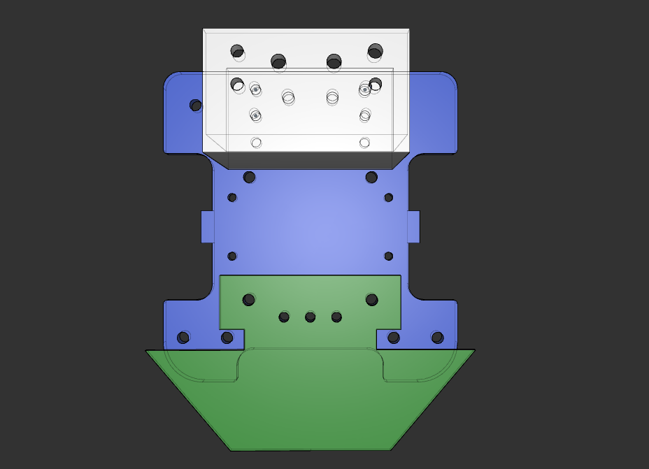
3D-printed base plate (bottom layer) - 1 - (~140×100 mm, see CAD files)
3D-printed electronics mount (top layer) - 1 - (Holds Arduino + driver)
3D-printed sensor bracket (front) - 1 - (Mounts 3 HC-SR04 sensors)
3D-printed motor mounts - 2 - (One per motor)
Rubber wheels (~65 mm dia.) - 2 - (Match N20 motor shaft diameter)
Caster wheel (rear) - 1 - (Ball caster or swivel caster)
M3 screws (8 mm, 12 mm) + M3 nuts - (~20 For all mounts)
NO 3D PRINTER: You can still build this robot. Cut the base plate from 3mm plywood or acrylic sheet using the dimensions in Step 2. The approximate overall footprint is 140 mm (front-to-back) × 100 mm (side-to-side). Motor mounts can be made from bent aluminium strip or L-brackets.
Chassis Assembly
CAD FILES Download the SolidWorks/STL files from Google Drive: https://drive.google.com/drive/folders/1kVgEDSZL84-ETg1oty_mleih7gymRfTq?usp=sharing — The folder contains STL files for the base plate, top mount, sensor bracket, and motor brackets. Slice at 0.2 mm layer height, 30% infill, PLA.
2A — Print / Cut the Base Plate
- Download and slice all STL files. Print with PLA at 0.2 mm layer height, 30% infill.
- If hand-cutting: cut the base plate to approximately 140 mm × 100 mm from 3 mm plywood or acrylic. Mark and drill the four motor mount holes (spacing matches N20 motor bracket pattern, typically 12 mm apart on each side) and the rear caster hole (centered, 20 mm from the rear edge).
- Allow prints to cool fully before removing supports.
2B — Attach the Motor Mounts
- Place one motor mount bracket over the left-side motor holes on the base plate. Thread two M3 × 8 mm screws through the bracket and into M3 nuts underneath the plate. Tighten until the bracket does not move when pushed.
- Repeat for the right-side motor mount bracket.
- Check: both motor mounts should be at the same position front-to-back and the same height off the plate.
2C — Install the Motors
- Slide one N20 motor into the left motor mount with the output shaft pointing outward (toward the wheel side). Secure with two M3 screws.
- Repeat for the right motor.
- Check: both motor shafts should be perfectly parallel to each other and level with the ground when the robot sits flat.
2D — Attach the Wheels
- Press one rubber wheel firmly onto the left motor shaft. The fit should be snug — if loose, use a small set screw or a drop of thread-locker.
- Repeat for the right wheel.
- Check: spin each wheel by hand. It should spin freely and not wobble.
2E — Install the Caster Wheel
- Position the caster wheel assembly at the rear-center hole of the base plate.
- Thread two M3 × 12 mm screws through the caster mount and base plate and secure with M3 nuts underneath.
- Check: the robot should now sit flat on a table with all three contact points (2 drive wheels + 1 caster) touching the surface evenly. If it rocks, adjust the caster mounting height.
2F — Mount the Sensor Bracket
- Attach the 3D-printed sensor bracket to the front of the base plate using two M3 × 8 mm screws.
- The bracket holds three HC-SR04 sensors: one pointing straight forward (0°), one angled left (~45°), one angled right (~45°).
- Snap or slide each HC-SR04 into its slot on the bracket. The sensor "eyes" (transducer cylinders) should face forward / outward, not upward.
2G — Mount the Electronics Layer
- Attach the top electronics mounting plate over the base plate using M3 standoffs (15–20 mm height) at the four corner holes.
- Place the Arduino Uno on the top plate and secure with two M3 × 8 mm screws through the Arduino mounting holes. The USB port should face the rear of the robot for easy programming access.
- Place the L298N motor driver module next to the Arduino on the top plate and secure with two M3 screws.
Circuit Wiring (L298N + Arduino)
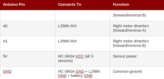
⚠️ IMPORTANT — VERIFY YOUR MOTOR DRIVER This build uses the standard L298N dual H-bridge module (the red rectangular board with a tall heatsink on top). The parts list, pin table, and wiring diagram below all match this module. If your board looks different, do not proceed until you verify its pinout.
3A — L298N Module Overview
The L298N module has these key connector groups:
- Power input: 12V (motor supply) and GND
- 5V output: can power Arduino logic (only if motor supply is 7–12V; for 6V battery, power Arduino separately)
- Motor outputs: OUT1, OUT2 (left motor), OUT3, OUT4 (right motor)
- Control inputs: IN1, IN2 (left motor direction), IN3, IN4 (right motor direction), ENA (left motor PWM speed), ENB (right motor PWM speed)
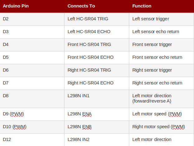
3B — Complete Pin Connection Table
- D2 - Left HC-SR04 TRIG - Left sensor trigger
- D3 - Left HC-SR04 ECHO - Left sensor echo return
- D4 - Front HC-SR04 TRIG - Front sensor trigger
- D5 - Front HC-SR04 ECHO - Front sensor echo return
- D6 - Right HC-SR04 TRIG - Right sensor trigger
- D7 - Right HC-SR04 ECHO - Right sensor echo return
- D8 - L298N IN1 - Left motor direction (forward/reverse A)
- D9 (PWM) - L298N ENA - Left motor speed (PWM)
- D10 (PWM) - L298N ENB - Right motor speed (PWM)
- D12 - L298N IN2 - Left motor direction (forward/reverse B)
- A0 - L298N IN3 - Right motor direction (forward/reverse A)
- A1 - L298N IN4 - Right motor direction (forward/reverse B)
- 5V - HC-SR04 VCC (all 3 sensors) - Sensor power
- GND - HC-SR04 GND + L298N GND + battery GND - (Common ground)
3C — Wiring Steps (in order)
- Ground first: Connect all GND pins together — Arduino GND, L298N GND terminal, battery negative, and all three sensor GND pins. Use a short breadboard strip or a common bus wire.
- Sensor power: Connect Arduino 5V to the VCC pin of all three HC-SR04 sensors in parallel.
- Sensor signals: Run four wires per sensor (TRIG and ECHO) to the Arduino digital pins listed in the table above. Label each wire end with tape while routing.
- Motor outputs: Connect the left motor’s two terminals to L298N OUT1 and OUT2. Connect the right motor’s two terminals to OUT3 and OUT4.
- Motor control signals: Connect L298N IN1, IN2, IN3, IN4, ENA, and ENB to the Arduino pins in the table above.
- Motor power: Connect the 6V AA battery pack positive to L298N 12V terminal (it accepts 5–46V, so 6V is fine). Connect battery negative to L298N GND.
- Logic power: Power the Arduino via USB during testing. For untethered operation, connect a separate 9V battery to the Arduino barrel jack, OR use the L298N 5V output if your motor supply is 7V or above.
- ENA/ENB jumpers: REMOVE the ENA and ENB jumper caps from the L298N board. These jumpers lock speed at 100% and prevent PWM speed control. With jumpers removed, ENA and ENB are driven by D9 and D10 from Arduino.
WIRING CHECK BEFORE POWER-ON Before applying power:
(1) Confirm no bare wire is touching the Arduino board directly.
(2) Confirm the motor battery negative and Arduino GND share a common point.
(3) Confirm ENA/ENB jumpers are removed.
(4) Confirm TRIG and ECHO are not swapped on any sensor.
Software — Upload & Code
The complete project code is available on Google Drive alongside the CAD files:
https://drive.google.com/drive/folders/1kVgEDSZL84-ETg1oty_mleih7gymRfTq?usp=sharing
4A — Install Arduino IDE
- Download and install Arduino IDE 2.x from arduino.cc
- Connect the Arduino Uno to your computer with a USB-A to USB-B cable.
- In Arduino IDE: Tools → Board → Arduino Uno. Tools → Port → select the correct COM/ttyUSB port.
4B — Open and Understand the Code
Before uploading, read through the sketch once and locate these five key sections. Understanding them lets you tune the robot without guessing:
- Pin definitions (top of sketch): All TRIG, ECHO, IN1–IN4, ENA, ENB pin numbers are defined as constants at the very top. Check that each number matches your actual wiring from Step 3 before uploading. A single wrong pin number here causes hours of debugging.
- WALL_DISTANCE threshold: This constant defines the distance in centimetres below which the robot treats a reading as a wall. The default starting value is 15 cm. If your maze cell is smaller or larger, you will need to change this after testing in Step 5.
- BASE_SPEED (motor PWM): This sets the PWM value (0–255) sent to both motors for forward movement. Default is 150. Lower values give more control at the cost of speed. If the robot stalls on carpet or rough surfaces, increase this value.
- TURN_TIME_MS: This constant defines how many milliseconds the robot runs its turn routine for a 90-degree turn. This is the most important tuning variable — too high and the robot over-rotates, too low and it under-rotates. You will adjust this in Test 4.
- Main loop (loop() function): This is where everything comes together. The loop reads all three sensors, evaluates the left-hand rule decision tree, and calls the correct movement function (moveForward, turnLeft, turnRight, or uTurn). Read through this once so you understand what the robot is deciding at each step.
4C — Upload the Code
- Open the .ino sketch file from the Drive folder in Arduino IDE.
- Click the checkmark (Verify) button first. Confirm it compiles with no errors.
- Click the arrow (Upload) button. Wait for "Upload complete" in the status bar.
- If upload fails: check the COM port selection and USB cable.
Here's the code, embedded using Codebender!
Try downloading the Codebender plugin and clicking on the "Run on Arduino" button to program your Arduino board. And that's it, you've programmed your Arduino with this sketch! (Due to their updates on their website we are not able to see the webpage here so i had shared you the link, once the Codebender beta is complete you will be able to see the full code here and you can make the changes based on your need and i had shared the dive link of my project and find the code over there).
Testing and Tuning
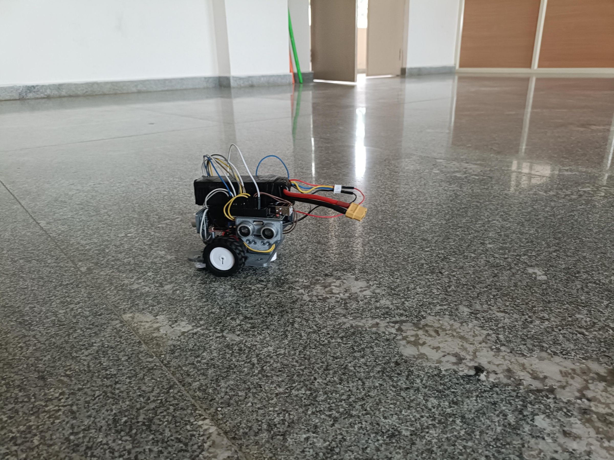
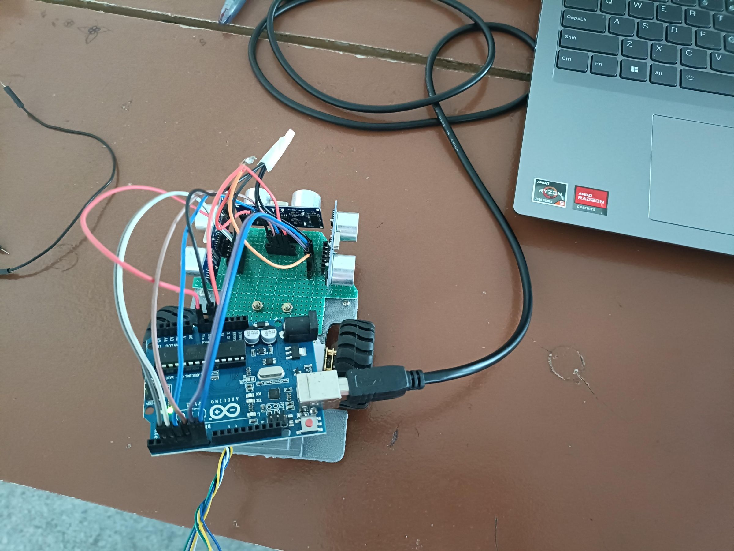
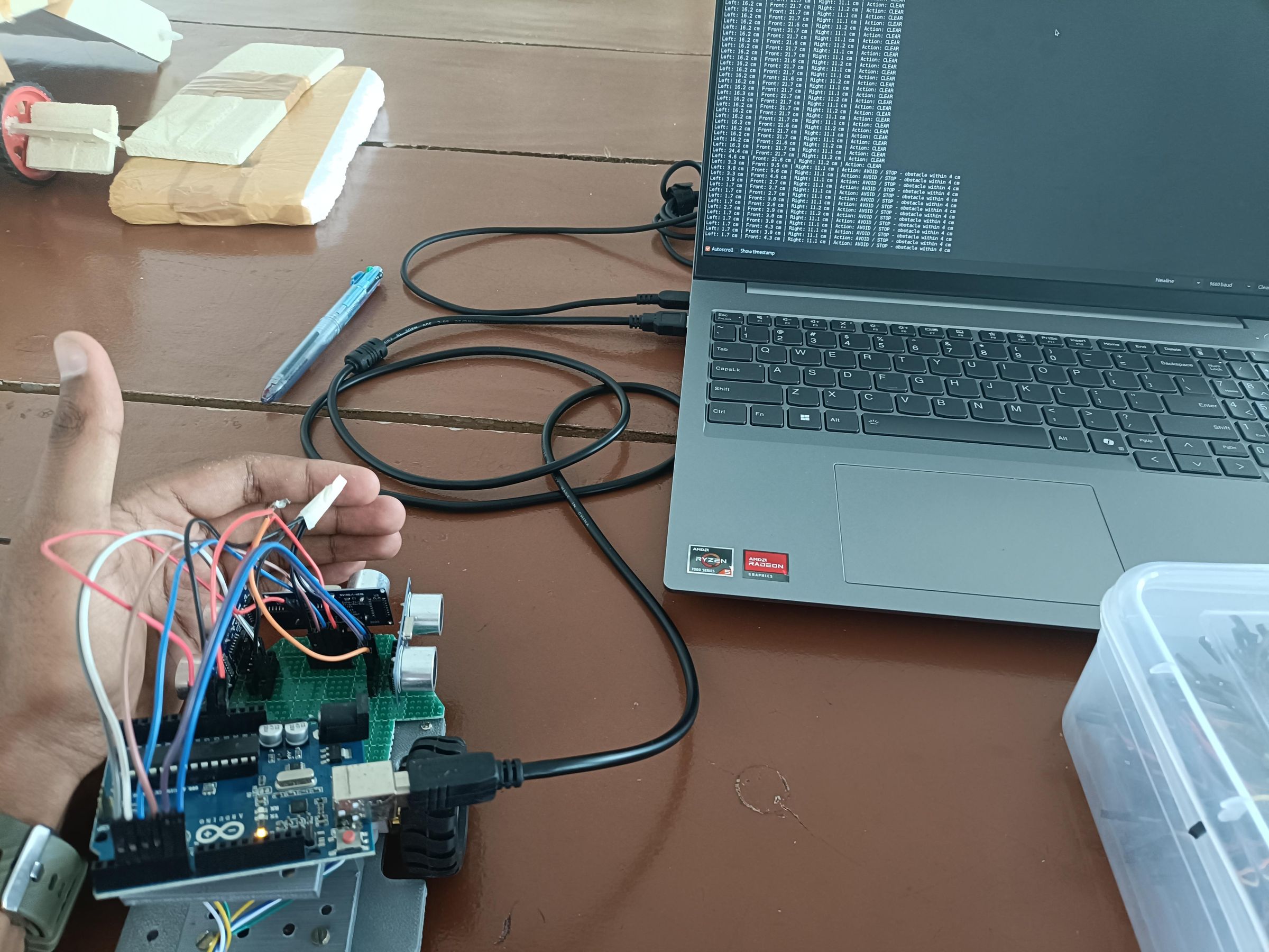
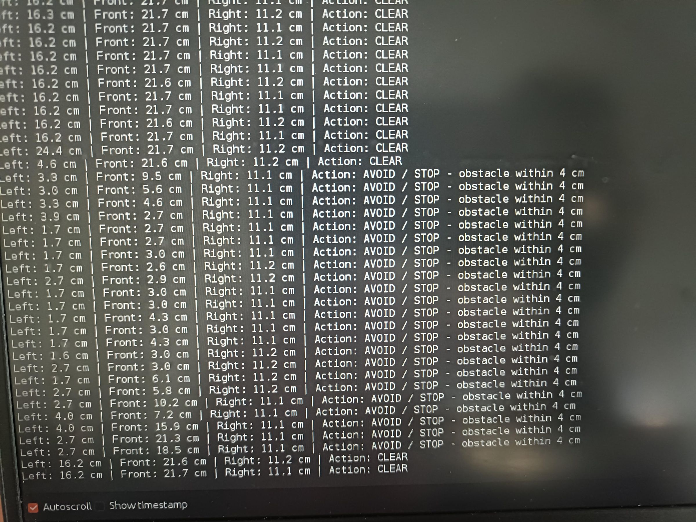
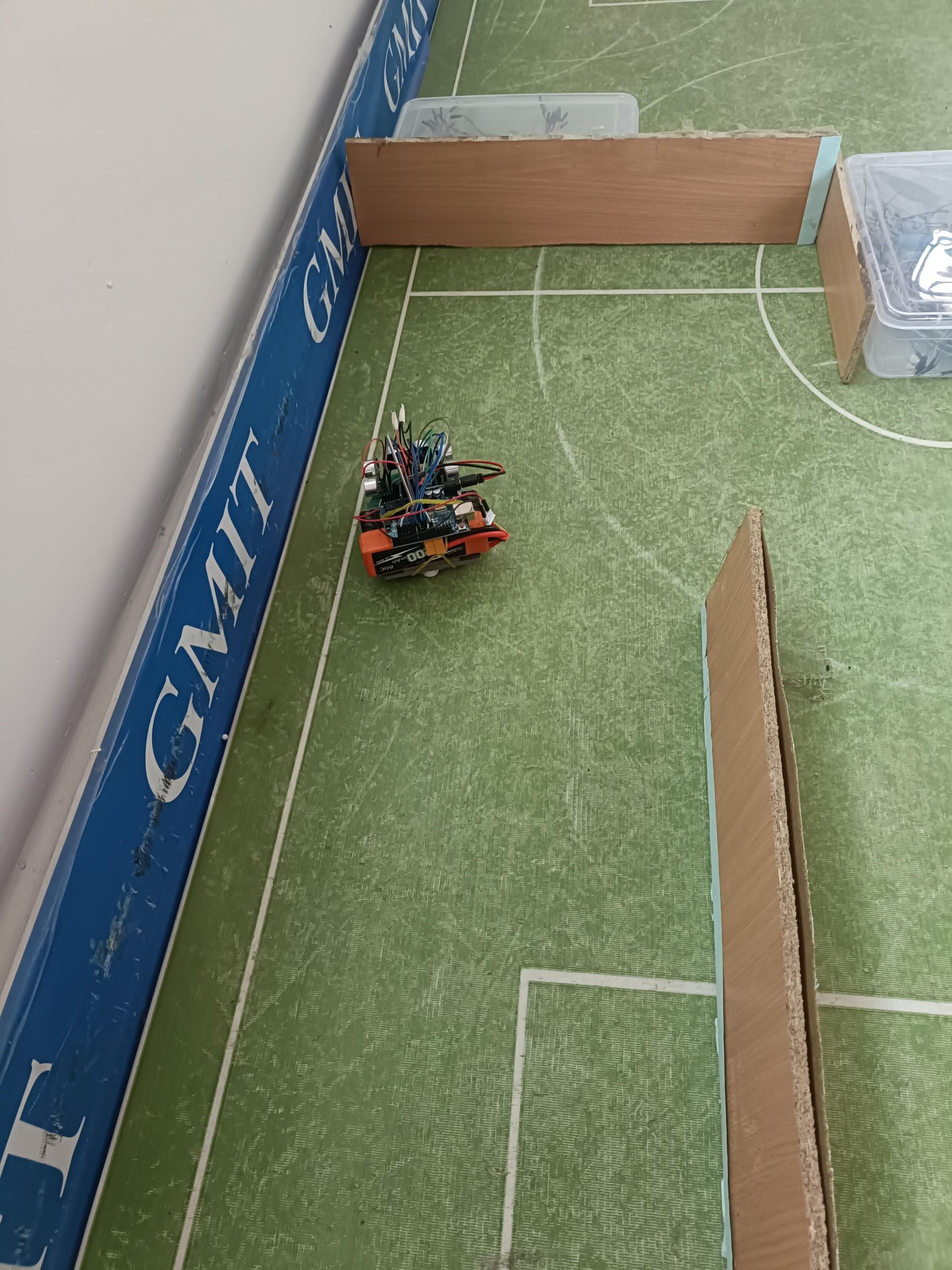
⚠️ DO NOT TEST IN A FULL MAZE FIRST Always test each subsystem individually before placing the robot in a maze. A robot that jumps straight to maze testing wastes hours debugging when the problem is a single loose wire.
Test 1 — Motor Direction
- Open Arduino IDE Serial Monitor (Ctrl + Shift + M). Set baud rate to 9600.
- Upload a simple motor test sketch that runs the left motor forward for 1 second, then stops, then runs the right motor forward for 1 second, then stops.
- Watch the wheels. Both should spin in the correct forward direction. If a wheel spins backward, swap its two motor wires at the L298N output terminal.
- Check: both wheels spin at similar speed. If one is noticeably faster, note which one for later PWM tuning.
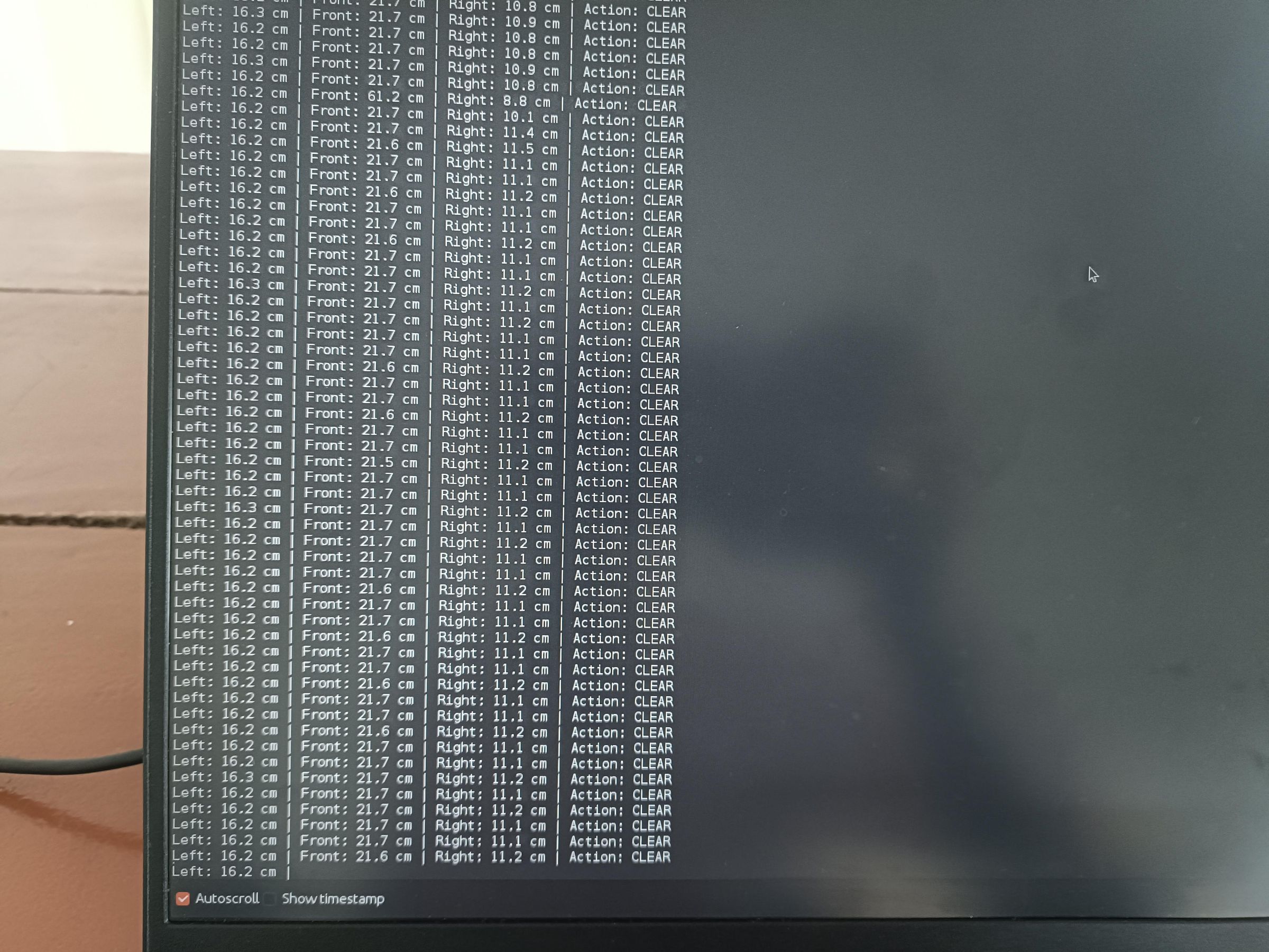
Test 2 — Sensor Readings
- Upload the main sketch. Open Serial Monitor.
- Hold your hand 10 cm in front of the left sensor. The Serial Monitor should show a left-wall reading around 10 cm.
- Repeat for front and right sensors.
- Move your hand away (beyond 30 cm) and confirm readings jump to the open-path value.
- Adjust WALL_DISTANCE if 15 cm is not correctly distinguishing wall vs. open in your maze cell size.
Test 3 — Straight Movement
- Place the robot on a smooth floor with a long straight corridor (or two parallel books).
- Power on and observe if the robot travels straight. If it curves left, increase the right motor PWM slightly (or decrease left). If it curves right, do the opposite.
- Adjust until the robot travels straight for at least 50 cm without drifting.
Test 4 — Turn Accuracy
- Place the robot at the start of a known 90-degree turn.
- The robot should complete the turn and end up aligned with the next corridor. If it over-turns or under-turns, adjust TURN_TIME_MS in the code.
- Test left turns and right turns independently. They may need different timing if the motors have different characteristics.
Test 5 — Simple Maze Run
- Build or set up a simple 3-cell maze with one corner and one dead end.
- Power the robot at the start. Observe how it handles the corner and the dead end.
- Fix any remaining threshold, speed, or turn-timing issues before testing in a larger maze.
Common Problems and Solutions
Problem Solution
Turns too much Decrease TURN_TIME_MS by 20–50 ms at a time
Turns too little Increase TURN_TIME_MS by 20–50 ms at a time
Drifts while going forward Adjust individual motor PWM values to compensate
Sensor readings unstable Add a 3–5 reading average in code; check for loose sensor wires
Wall threshold wrong Measure actual wall-to-sensor distance in your maze and set WALL_DISTANCE to 70% of that value
One motor much faster than other Set different PWM values per motor; N20 motors vary between units
Why This Project Is Useful
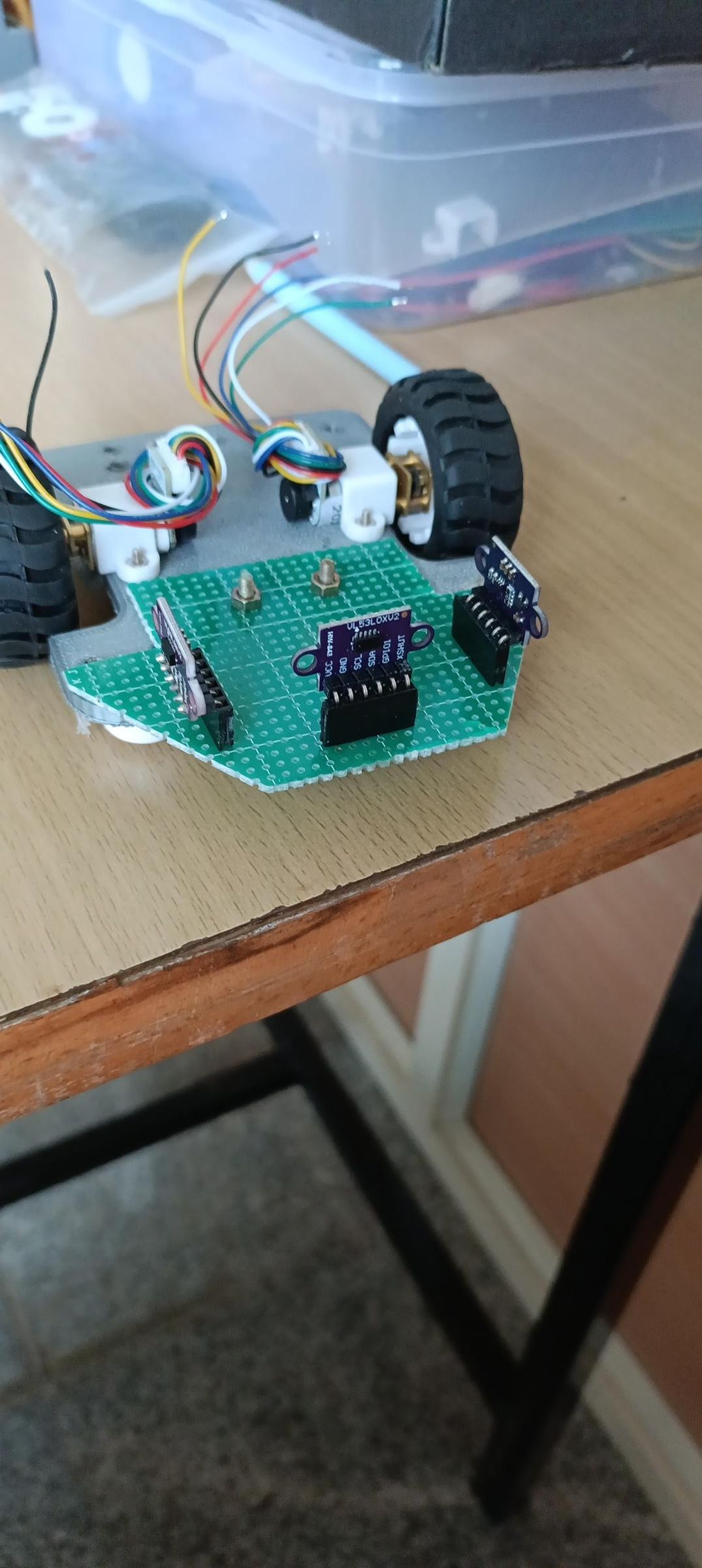
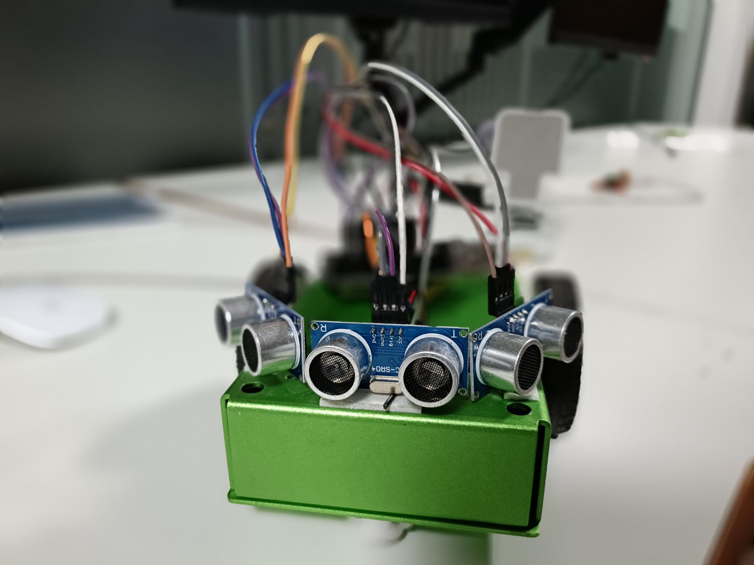
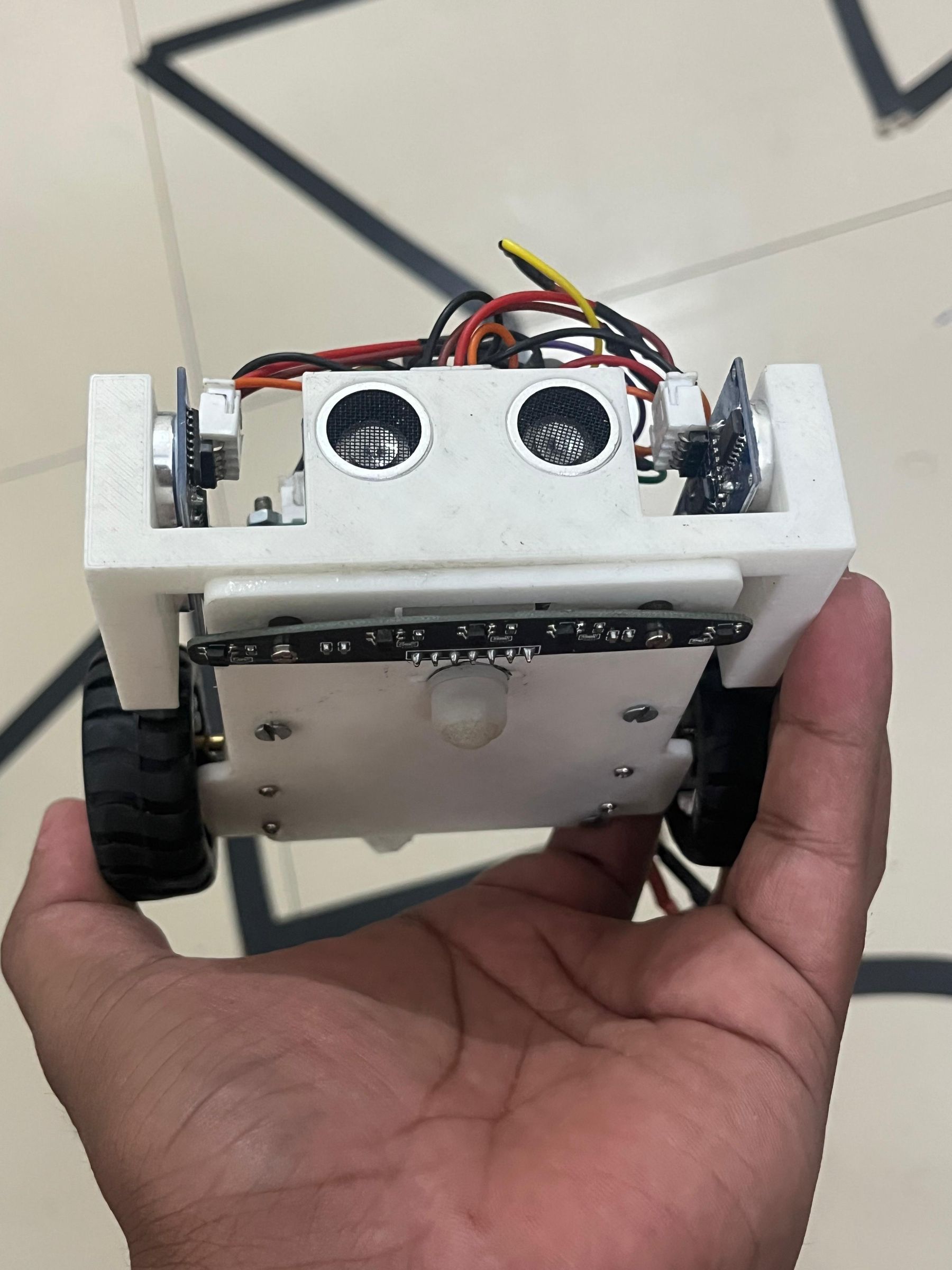
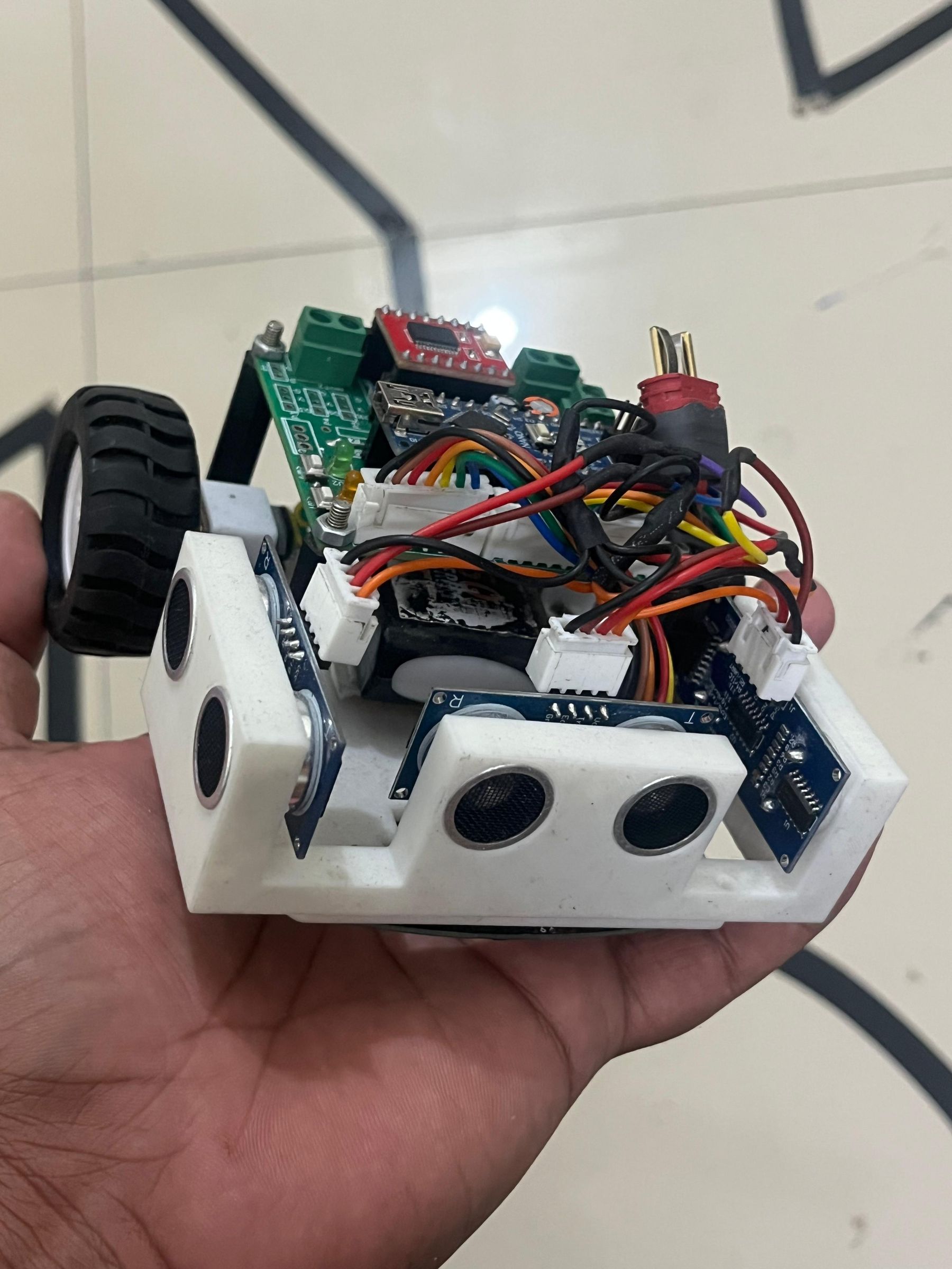
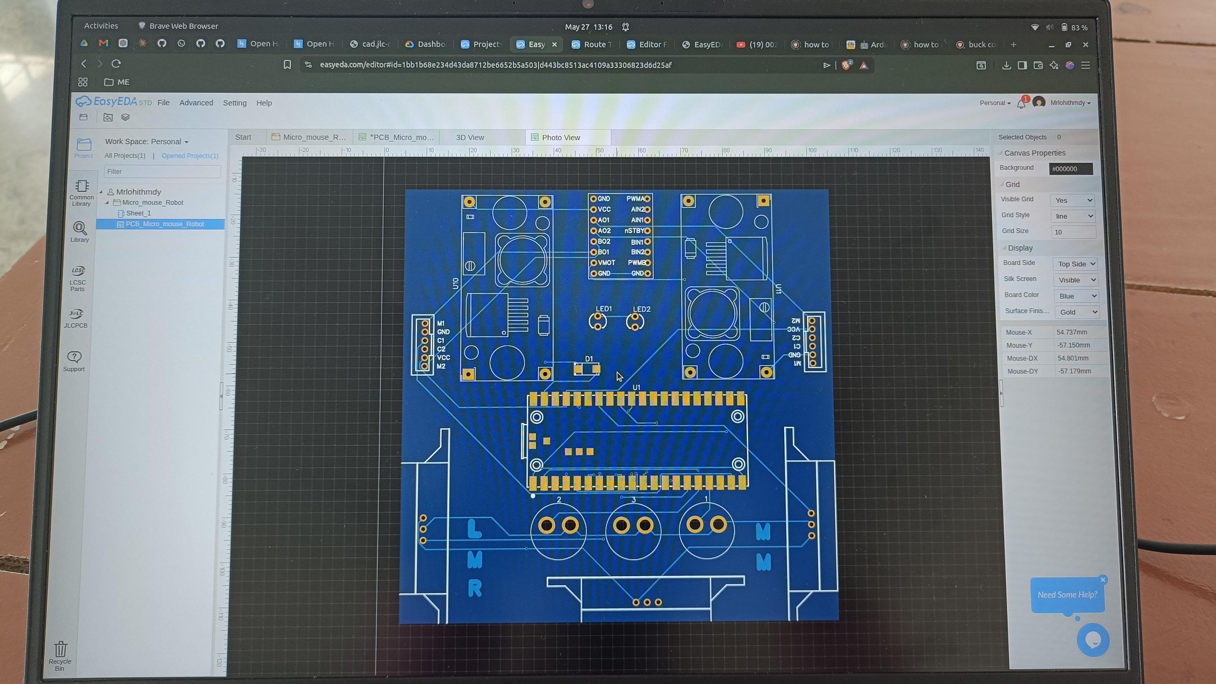
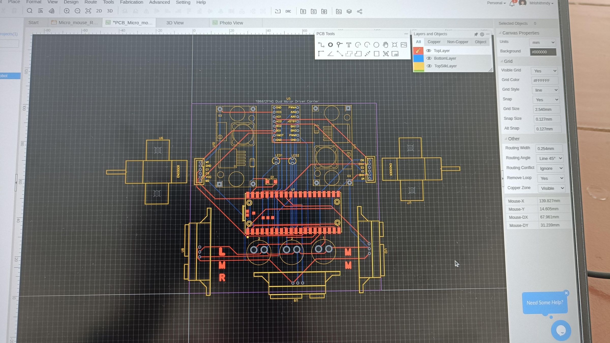
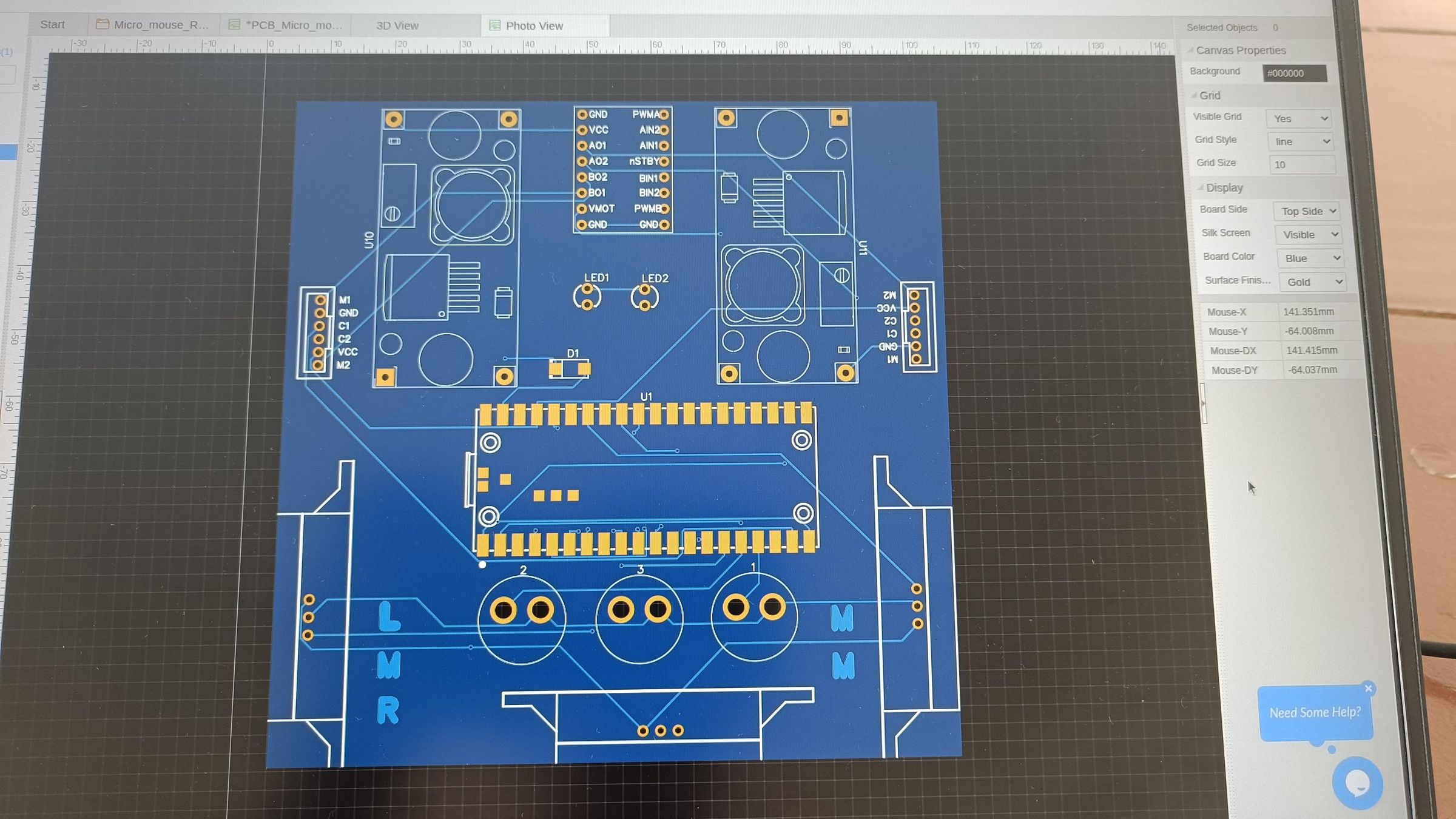
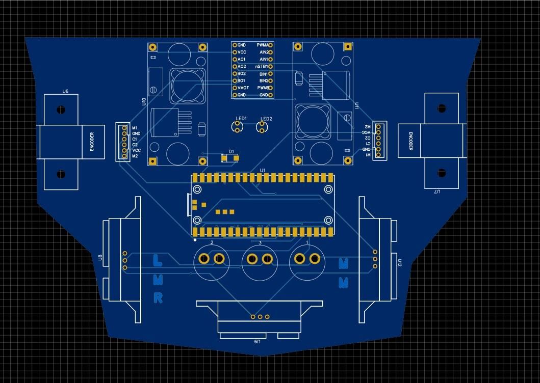
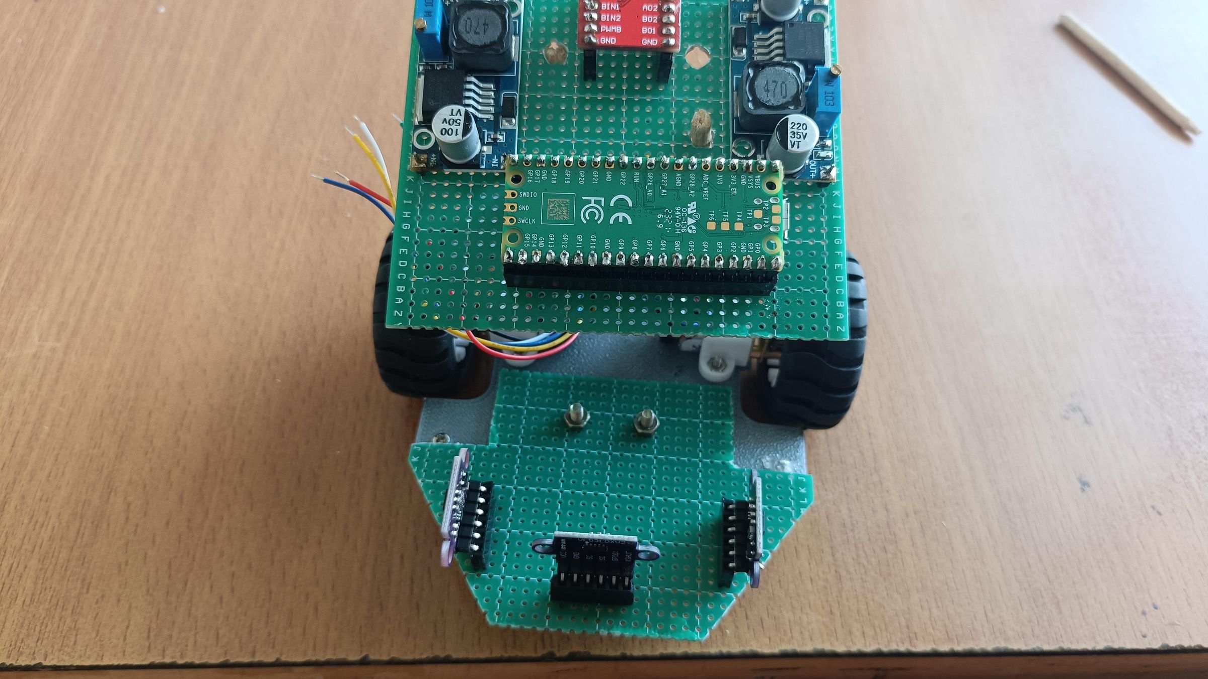
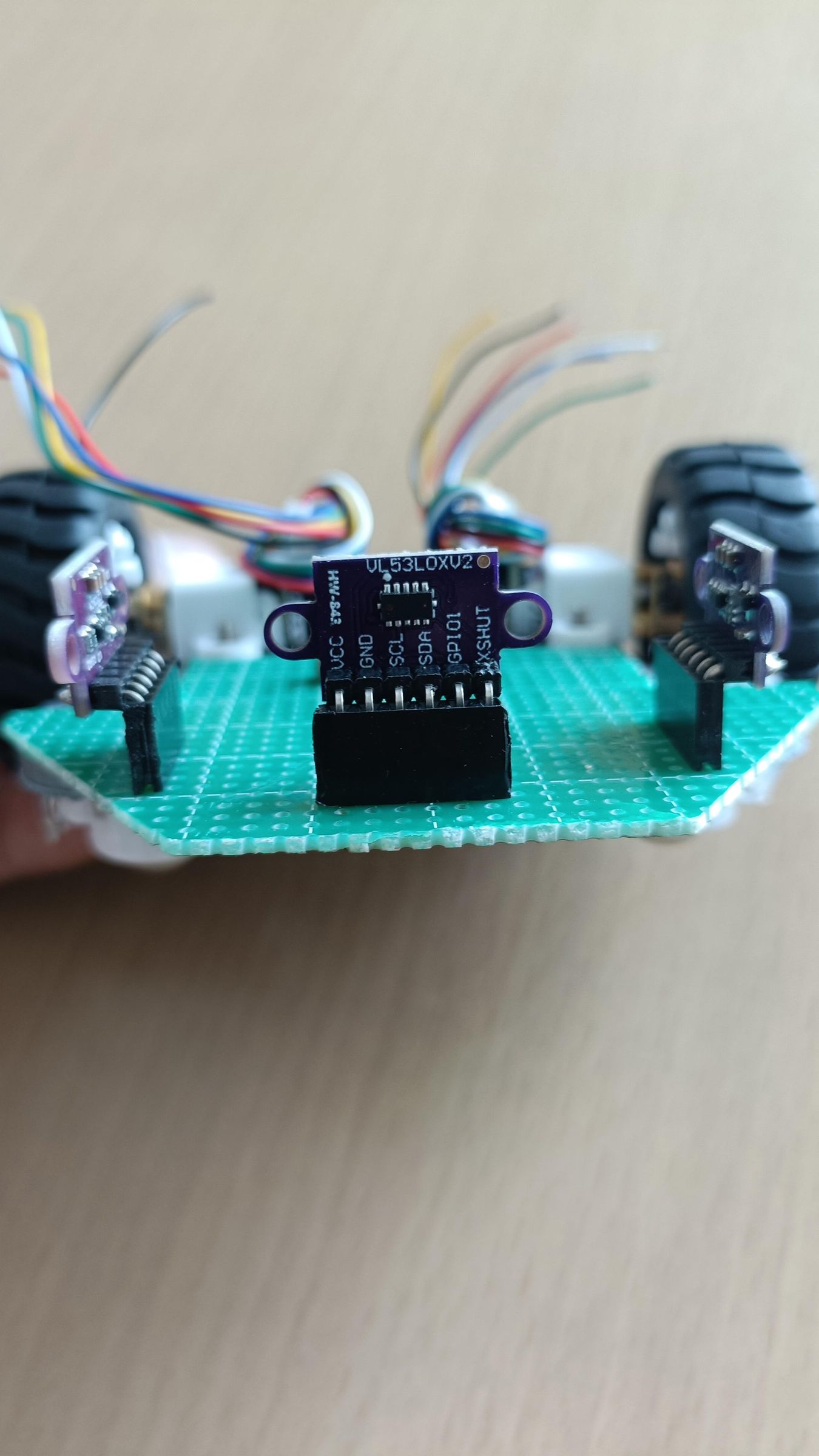
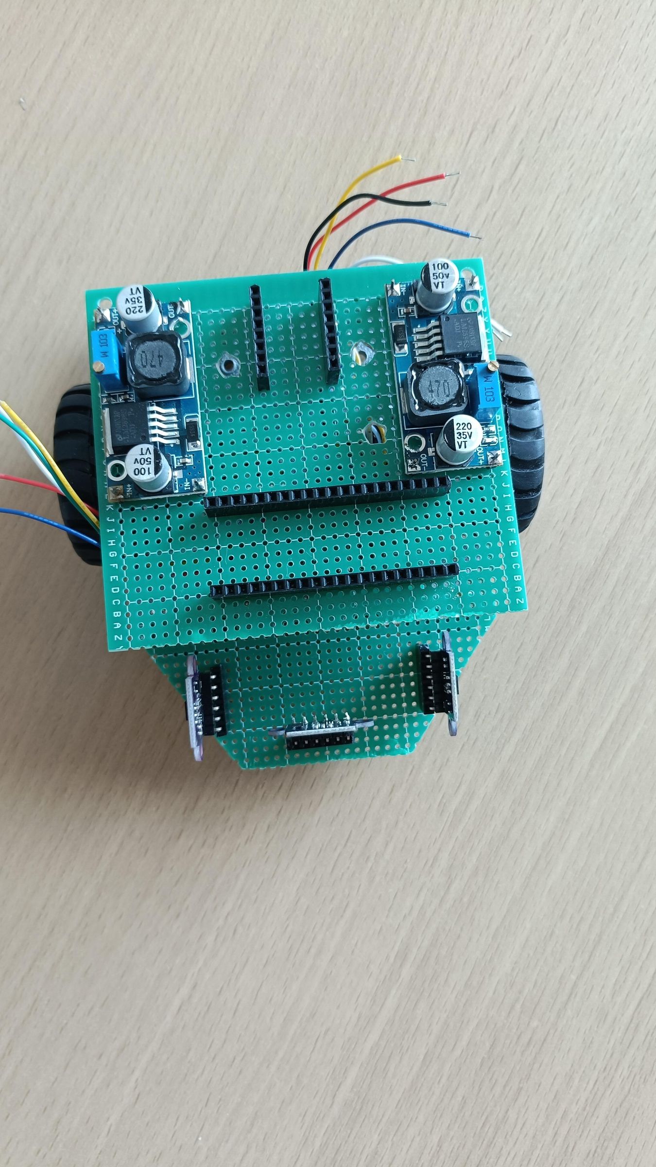
This project teaches how a robot can sense, decide, and move without human help. It introduces real-world robotics concepts that appear in every professional autonomous system:
- Sensor Filtering: The HC-SR04 ultrasonic sensors return noisy readings in real environments. This project teaches you how to set a reliable threshold distance and how to average multiple readings to eliminate false wall detections. This same technique is used in industrial proximity sensors and LIDAR systems.
- Motion Control: Getting two independent DC motors to produce straight, consistent movement requires balancing PWM values and understanding how small mechanical differences between motors cause drift. This is the foundation of differential-drive robot control used in everything from warehouse AGVs to rover robots.
- State Machine Design: The robot's behavior is structured as a state machine (IDLE → EXPLORE → MAP → FAST_RUN → FINISHED). This pattern appears in virtually every real autonomous system, from traffic light controllers to self-driving car decision layers.
- Path Planning: Choosing the best available move at each decision point using the Left-Hand Rule is the simplest form of graph traversal. Upgrading to Flood Fill or BFS directly introduces the core concepts behind GPS routing, ROS 2 Nav2, and warehouse automation path planners.
- Iterative Tuning and Calibration: This project is not plug-and-play. Adjusting WALL_DISTANCE, TURN_TIME_MS, and motor PWM ratios teaches the engineering mindset that no system works perfectly on the first attempt. Every real robotics project requires this kind of systematic testing and adjustment.
Even a simple left-hand rule Micromouse is a strong first step. From here, the Maze_Runner can be upgraded to Flood Fill maze solving, encoder-based closed-loop speed control, and IMU-assisted straight-line correction — building toward competition-level micromouse performance.
Stay tuned for the next upgraded version of this project on the Rino_Scientist channel.
Conclusion
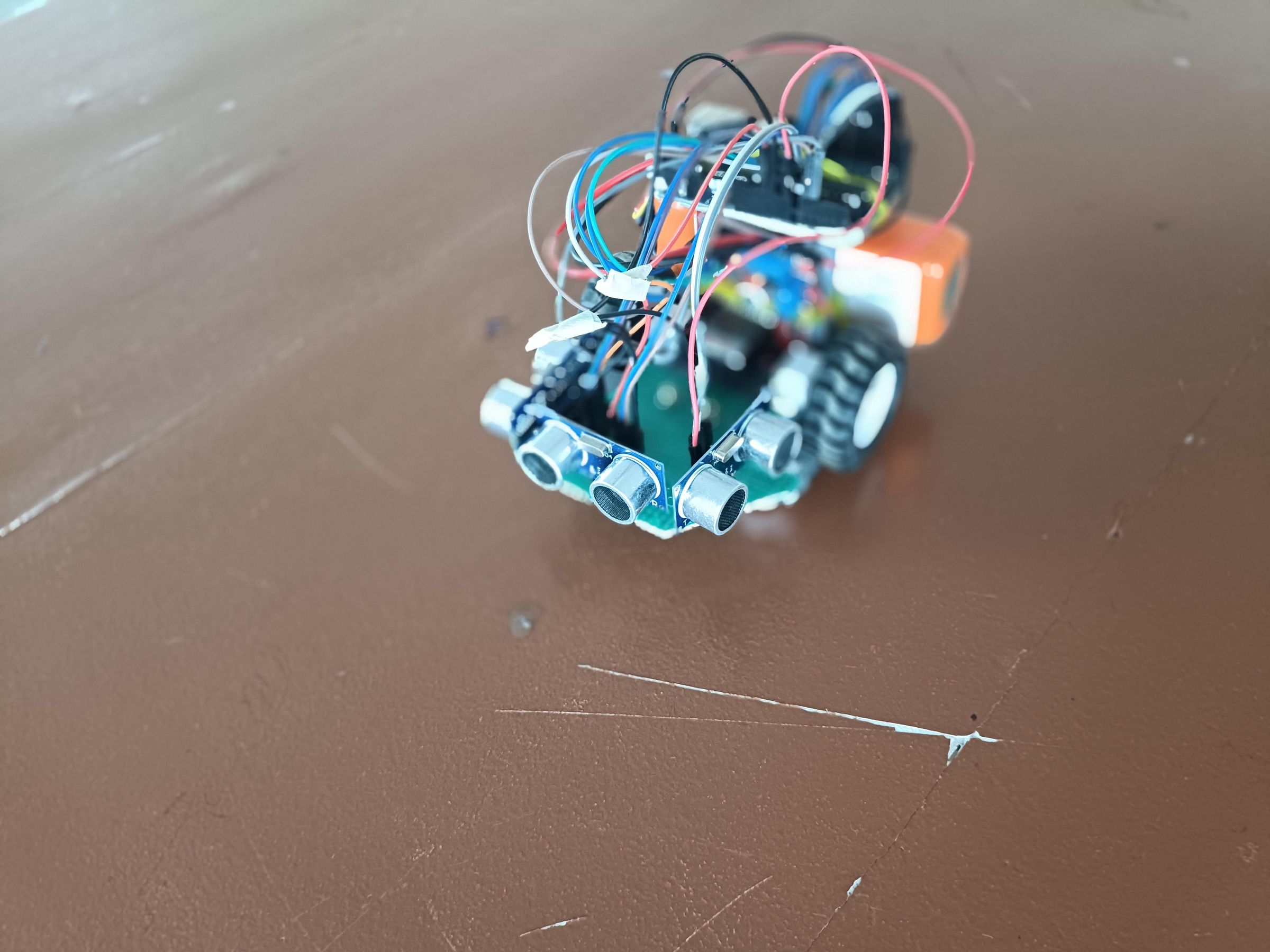
A maze-solving robot is a great beginner-to-intermediate robotics project because it combines hardware and software in one system. The core idea is straightforward: detect walls, choose a path, move, and repeat until the goal is reached.
If you build it carefully and test it subsystem by subsystem — motors first, then sensors, then movement, then maze — you will end up with a robot that works reliably in a real maze and serves as a strong foundation for every autonomous robotics project that follows.
Research
The following sources were used in researching and developing this guide. Each link is live and verified:
- Maze Solving Algorithms for Micro Mouse — ResearchGate (2009) https://www.researchgate.net/publication/224363078_Maze_Solving_Algorithms_for_Micro_Mouse Covers wall following, DFS, BFS, and flood fill approaches. Good starting point for understanding how maze-solving algorithms compare in practice.
- Solving the Maze — Micromouse Online https://micromouseonline.com/micromouse-book/mazes-and-maze-solving/solving-the-maze/ Written by Peter Harrison, one of the most experienced micromouse builders in the UK. Explains flood fill in depth with clear step-by-step logic and discusses why wall-following fails in competition mazes.
- Maze Solver Algorithms inspired on Micromouse Competition — ResearchGate (2019) https://www.researchgate.net/publication/332438251_Maze_Solver_Algorithms_inspired_on_Micromouse_Competition Compares flood fill and wall-following (line follower) algorithms. Discusses sensor types and identifies conditions where each algorithm succeeds or fails.
- An Algorithm of Micromouse Maze Solving — IEEE Xplore (2010) https://ieeexplore.ieee.org/document/5578409/ Proposes the Partition-central Algorithm for efficient maze exploration in 16×16 competition mazes. Peer-reviewed IEEE conference paper with simulation results.
- A Robust Maze Solving Algorithm for a Micromouse Robot — ResearchGate (2011) https://www.researchgate.net/publication/272001393_A_Robust_Maze_Solving_Algorithm_for_a_Micromouse_Robot Proposes two computationally efficient algorithms that explore the maze partially rather than fully before finding the shortest path. Good for understanding how to optimise exploration time.
- A Comprehensive and Comparative Study of Maze-Solving Techniques by Implementing Graph Theory — ResearchGate (2010) https://www.researchgate.net/publication/224202469_A_Comprehensive_and_Comparative_Study_of_Maze-Solving_Techniques_by_Implementing_Graph_Theory Explains how graph theory algorithms (DFS, BFS, Dijkstra) apply directly to micromouse maze solving. Demonstrates why graph-theory-based approaches outperform non-graph methods.
- MAZE Robot With Arduino — Instructables https://www.instructables.com/MAZE-Robot-With-Arduino/ A complete Arduino-based maze robot build on Instructables. Used as a reference for guide structure, step sequencing, and how to present wiring diagrams in this format.
- Maze Solving Robot : 13 Steps — Instructables https://www.instructables.com/Maze-Solving-Robot/ A 13-step build guide with detailed photos at each stage. Referenced for the standard of photo documentation and step-level detail expected in a complete Instructables build guide.
- Maze-Solving Robot / MicroMouse / Wall-Following Robot — Instructables https://www.instructables.com/Maze-Solving-Robot-MicroMouse/ A closely related project covering wall-following micromouse construction. Helpful for comparing chassis layouts, sensor mounting approaches, and how others have solved common build problems.
- Autonomous Maze Solving Robot — GitHub (Arduino-based) https://github.com/mrRobot62/micromouse Open-source Arduino-based micromouse code repository. Useful for seeing a practical implementation of sensor reading, motor control, and state machine structure in actual Arduino C++ code.
- Micromouse Construction Tutorial Part 1 — Micromouse Online https://micromouseonline.com/micromouse-book/ The full Micromouse Online book by Peter Harrison. Covers mechanical construction, sensor selection and placement, motor selection, and power systems for competition-level micromouse builds.
- Faster Maze Solving — Micromouse Online https://micromouseonline.com/micromouse-book/mazes-and-maze-solving/faster-maze-solving/ Explains queue-based flood fill and how to optimise straight-line and turning calibration for speed runs after maze exploration is complete.
- UCLA IEEE — Micromouse 2022 Lecture 1: Introduction and Power (YouTube) https://www.youtube.com/watch?v=JCpBrNhBpik Lecture series from UCLA IEEE covering micromouse hardware selection, power systems, motor driver circuits, and sensor fundamentals from a university engineering course perspective.