MIMOTUS V1: a Tendon-Driven Robotic Finger for Human Motion Transfer
by Uttkarsh121 in Circuits > Electronics
16 Views, 1 Favorites, 0 Comments
MIMOTUS V1: a Tendon-Driven Robotic Finger for Human Motion Transfer
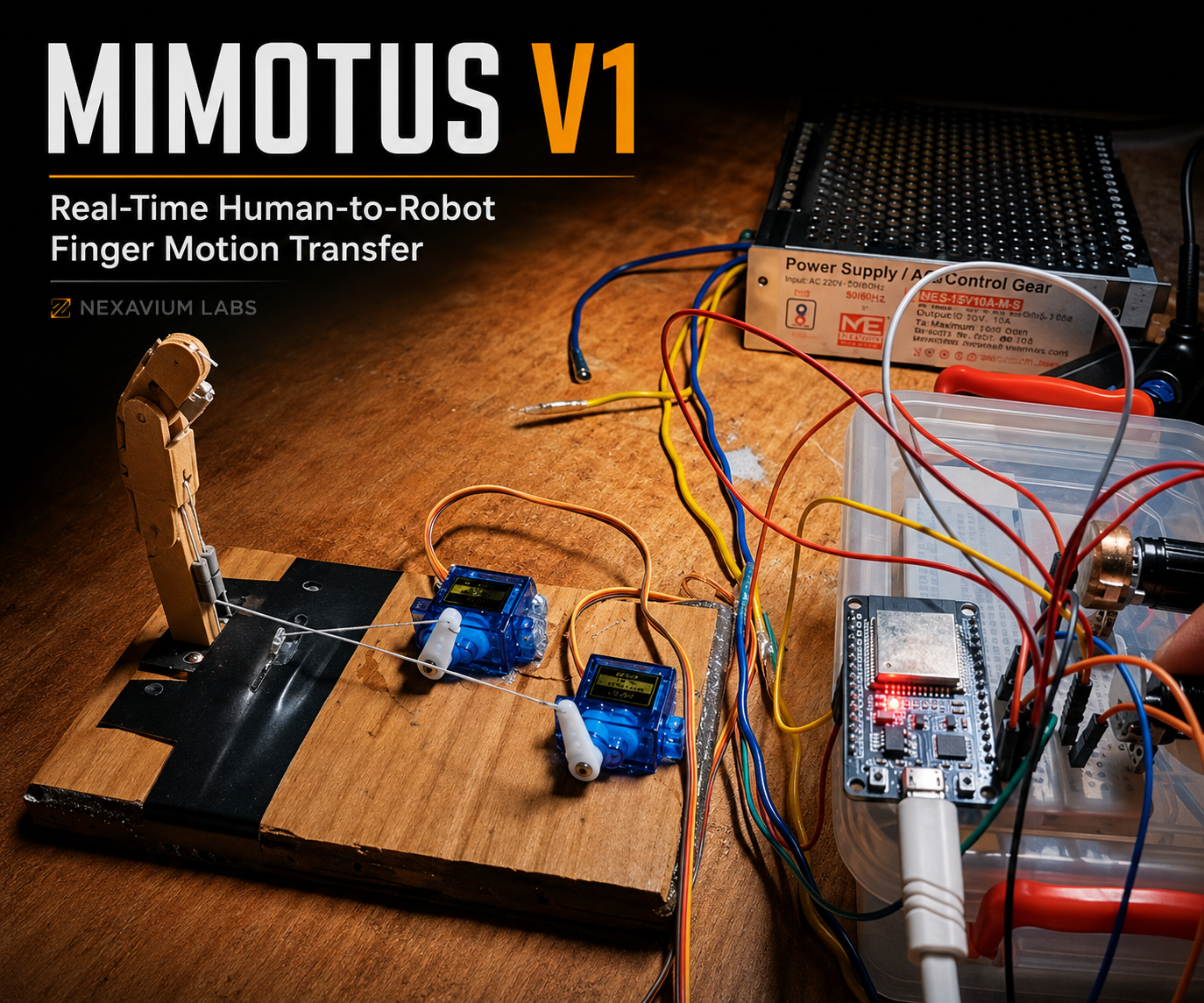
Introduction: MIMOTUS V1 – Tendon-Driven Robotic Finger
MIMOTUS is an experimental human-to-robot motion transfer project.
The long-term goal is to develop a system in which movements of a human body can be captured and reproduced by a robotic counterpart in real time. Possible future applications include robotic teleoperation, hazardous-environment manipulation, research, and high-performance robotic systems.
This first prototype focuses on the smallest useful version of that problem: a human index finger and a robotic index finger with two independently controllable joints.
Before adding human-motion sensors, I first wanted to prove that the robotic side itself could work reliably.
For this prototype I built a lightweight robotic finger using ice-cream sticks, steel-wire hinge pins, thread tendons, two SG90 servo motors, an ESP32, and two potentiometers.
Each potentiometer currently represents one future human joint sensor:
Potentiometer 1 → Servo 1 → Tendon 1 → Joint 1
Potentiometer 2 → Servo 2 → Tendon 2 → Joint 2
The mechanical design went through several iterations. Tendon friction, joint coupling, hinge geometry, and actuator loading all caused problems during development. One SG90 servo was even damaged while testing an inefficient tendon path.
After redesigning the tendon routing, both joints successfully completed 20 repeated actuation cycles.
This Instructable documents the mechanical and servo-control stage of MIMOTUS V1. The next stage will replace the potentiometers with sensors mounted on a human finger so that the robotic finger can imitate actual human joint movement.
Downloads
Supplies
.jpeg)
Electronics
- 1 × ESP32 DevKit
- 2 × SG90 180° positional servo motors
- 2 × 1 kΩ potentiometers
- 1 × 5 V high-current power supply / SMPS
- Breadboard
- Jumper wires
- USB cable for ESP32 programming
Mechanical parts
- Ice-cream sticks
- Cardboard
- Plain uncoated kite thread / saddi
- Binder-clip or stiff steel wire for hinge pins
- Small pieces of smooth tubing/fabric for tendon guides
- Hot-glue gun and glue sticks
- Scissors/cutter
- Needle, push pin, or similar tool for making small holes
Software
- Arduino IDE
- ESP32 board support
- ESP32Servo library
Define the Finger Geometry
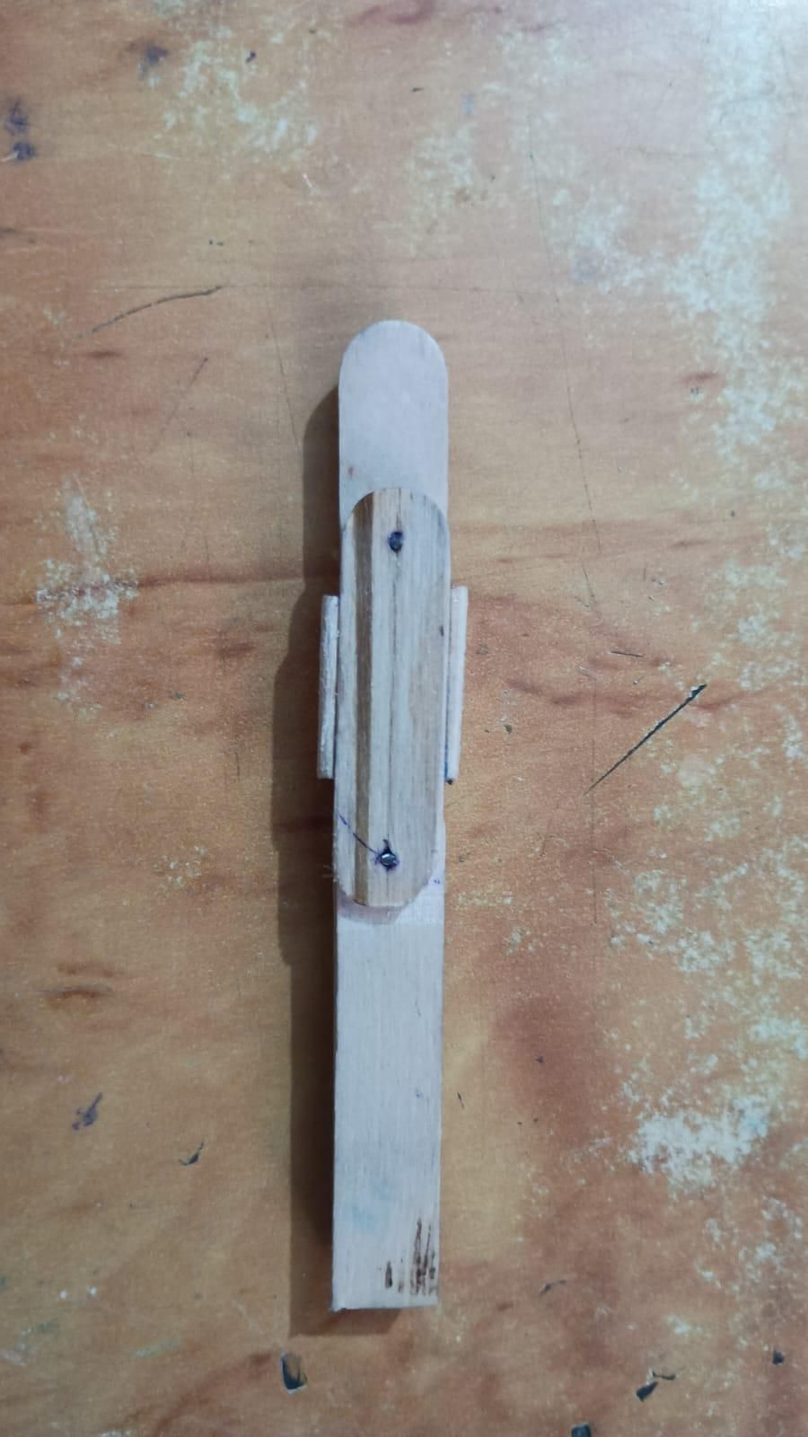
Step 1: Define the Finger Geometry
The robotic finger consists of three rigid links representing the main sections of an index finger.
I measured my own index finger and used approximately:
Link 1: 50 mm
Link 2: 40 mm
Link 3: 25 mm
Link 1 was made stronger using three laminated ice-cream-stick layers. The smaller links used lighter construction to reduce moving mass.
The prototype uses two actively controlled joints:
J1 – lower joint between Link 1 and Link 2
J2 – upper joint between Link 2 and Link 3
The objective was not to reproduce the biological finger perfectly. The objective was to create a lightweight two-degree-of-freedom mechanism that could later reproduce measured human joint motion.
Build the Hinged Joints
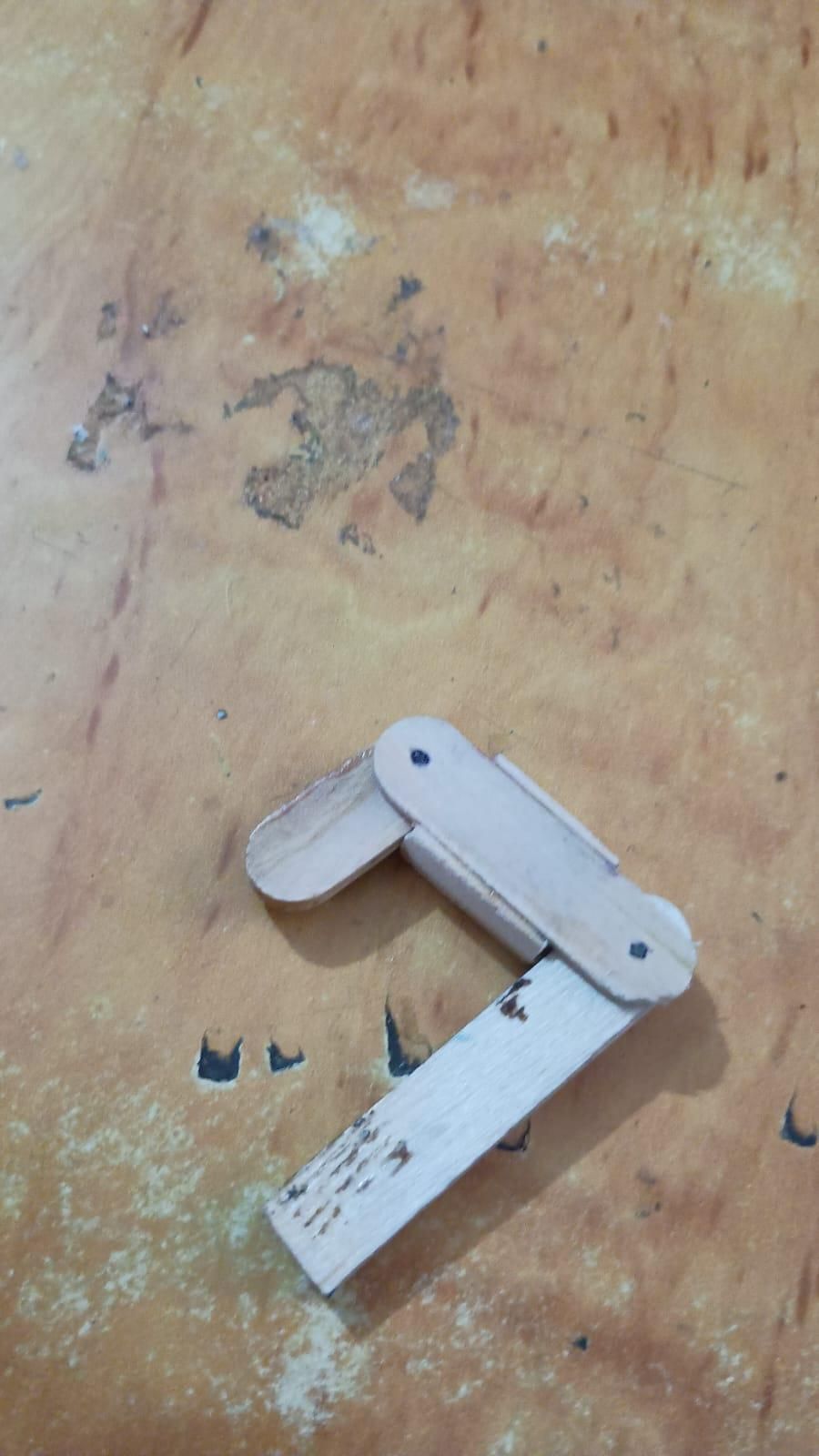
Step 2: Build the Hinged Vertebrae
The first challenge was making joints that could rotate freely without twisting sideways.
The links were connected using a small fork-style hinge mechanism.
Small wooden side pieces form the two cheeks of the joint, while the moving link sits between them. A piece of stiff steel wire passes through aligned holes and acts as the hinge pin.
This arrangement provides better alignment than simply overlapping two flat sticks.
Before permanently assembling the joints, check that:
- the joint rotates at least approximately 90°,
- very little force is required,
- there is no major sideways wobble,
- the wooden surfaces do not clamp tightly against each other.
Small friction is acceptable for an early prototype, but a servo should never have to fight a mechanically jammed joint.
Important lesson
Fix friction before adding motors.
A powerful actuator does not repair bad mechanics. It merely destroys them more enthusiastically. 😭
Route the Tendons
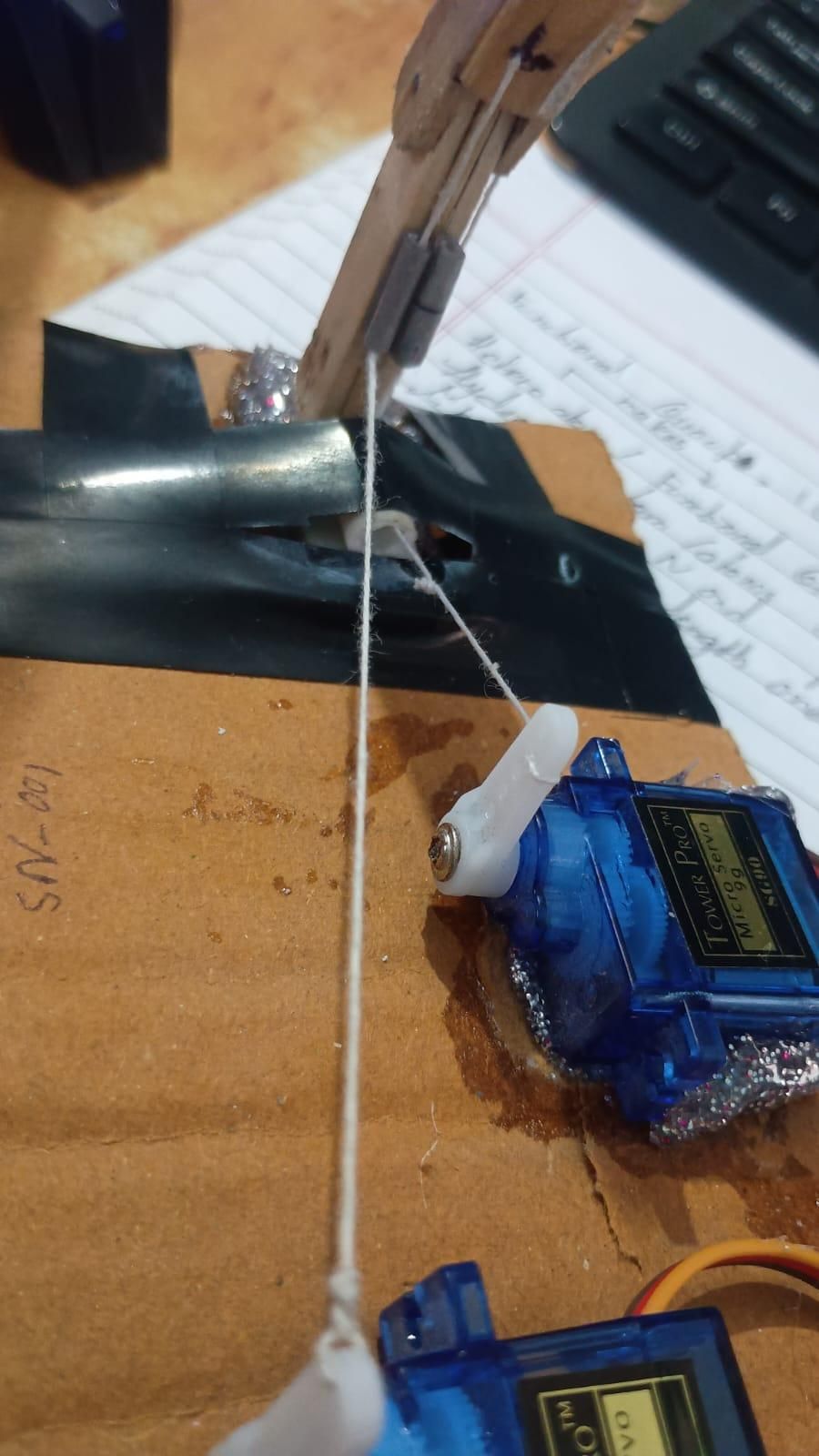
Step 3: Route the Tendons
The finger uses two independent tendons.
T1 controls J1.
T2 controls J2.
Plain uncoated kite thread, called saddi in India, was used for the prototype.
The tendon must run on the inside of the direction in which the finger bends. Pulling the tendon then generates torque around the hinge.
The tendon should not simply pass directly through the hinge axis. A small offset from the pivot creates the moment arm needed to rotate the joint.
Small guide sleeves were attached along the finger to control the thread path and prevent it from wandering sideways.
The thread itself must remain free to slide. Do not glue the tendon to the guide.
Reduce Tendon Coupling
Step 4: Reduce Tendon Coupling Between J1 and J2
Tendon 2 created an interesting mechanical problem.
Because T2 must travel past J1 before reaching the actuator, pulling T2 initially produced torque around both J1 and J2.
This caused the lower joint to bend whenever I tried to move the fingertip.
The solution was based on a simple torque relationship:
Torque = Tendon Force × Distance From the Joint Axis
For J2, T2 needs a useful offset from the hinge so it can generate bending torque.
But when T2 passes J1, it should travel very close to the J1 pivot axis. This reduces its moment arm around J1 and therefore reduces unwanted movement of the lower joint.
After modifying the guides and reducing friction, the two joints could be controlled much more independently.
This was one of the most important mechanical lessons from the prototype.
Servo Failure and Mechanical Debugging
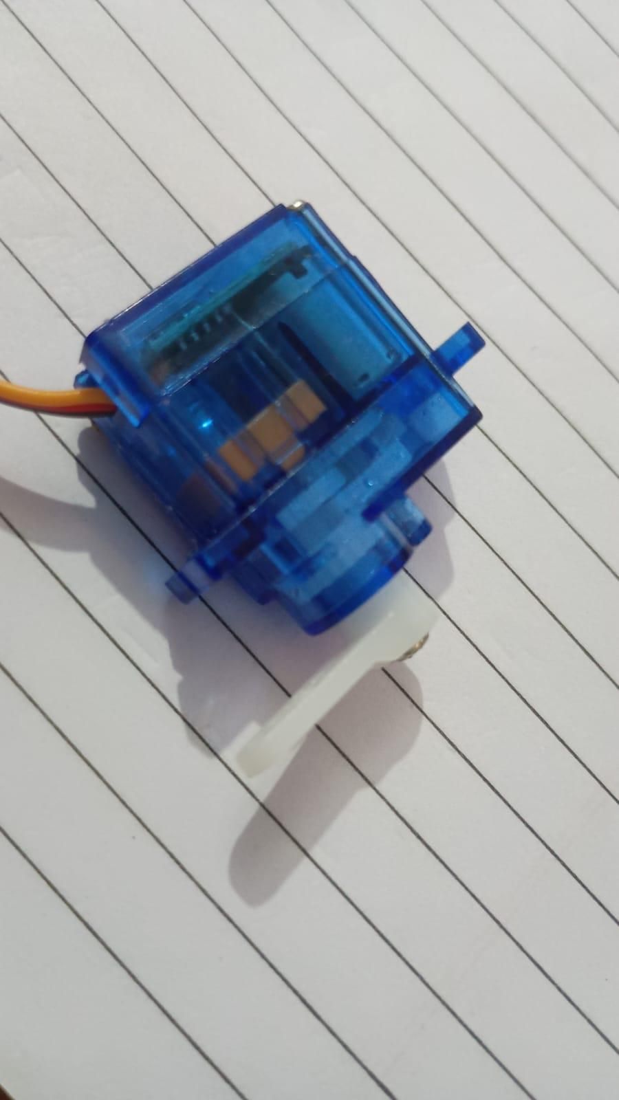
Step 5: Servo Failure and Mechanical Debugging
During early testing, the T2 mechanism had too much friction and required excessive pulling force.
I initially connected it to an SG90 anyway.
That SG90 did not enjoy the experience.
The servo eventually failed.
Instead of immediately installing another servo, I disconnected the actuator and manually tested the entire T2 path.
The tendon routing was modified until J2 could be actuated smoothly by hand. Friction around the guides was reduced and the geometry near the joints was corrected.
Only after the mechanism moved freely was another servo installed.
Lesson learned
Never use a stronger motor to hide a mechanical problem.
If a servo is continuously buzzing while the mechanism is not moving, it is probably stalled. Cut the power and fix the mechanical load before continuing.
The dead SG90 has now been retained as an extremely small and extremely expensive teaching assistant. 💀
Build the Actuator Base
Step 6: Build the Actuator Base
The completed finger was mounted vertically onto a rigid cardboard platform.
I laminated multiple cardboard layers together so that the base would not flex significantly when the servos pulled the tendons.
Only Link 1 is rigidly attached to the base.
J1 and J2 remain completely free to rotate.
Two SG90 servos are mounted behind the finger. Each tendon runs from the finger toward its corresponding servo horn.
The actuators remain on the base rather than being mounted directly on the finger. This keeps moving mass low and makes the mechanism easier to control.
Before attaching the tendons, both servos should be moved to a known neutral position.
Connect the ESP32, Potentiometers and Servos
.jpeg)
Step 7: Connect the ESP32, Potentiometers and Servos
The two potentiometers are read by the ESP32 ADC.
I used:
Potentiometer 1 wiper → GPIO 34
Potentiometer 2 wiper → GPIO 35
The potentiometer outer terminals connect to:
3.3 V and GND
Do not feed 5 V into the ESP32 ADC input.
Servo signals:
Servo 1 signal → GPIO 18
Servo 2 signal → GPIO 19
The SG90 motors are powered from an external 5 V supply, not from the ESP32.
The ESP32 ground and servo-power-supply ground must be connected together to provide a common signal reference.
Wiring summary
If you're using an open-frame mains SMPS, keep the AC terminals properly enclosed and insulated.
Potentiometer-to-Servo Control
Step 8: Potentiometer-to-Servo Control
Install the ESP32Servo library in Arduino IDE.
Use the following program for initial testing:
The exact servo limits will depend on the tendon geometry.
Start with a small range and increase it gradually.
Never immediately command the servo through its maximum possible travel while the tendon is attached.
Calibrate the Tendons
Step 9: Calibrate the Tendons
The servo horn position, tendon length, and joint geometry determine how much servo movement is required.
The correct procedure is:
Start with the finger straight.
Set the servo to its neutral position.
Attach the tendon so that it is just taut.
There should be almost no preload on the servo.
Gradually increase the servo angle while observing the joint.
Stop increasing the range when the required maximum finger bend is reached.
Record the safe straight and bent positions for each servo and use those values in the code.
If the servo buzzes while the joint remains stationary, immediately remove power and inspect the mechanism.
Reliability Testing
Step 10: Reliability Testing
Once both joints were operating correctly, I tested them repeatedly instead of judging the prototype from a single successful motion.
Each tendon/joint system completed 20 consecutive actuation cycles.
I checked for:
- tendon slipping,
- knot movement,
- increased friction,
- servo stalls,
- cardboard-base movement,
- joint binding,
- inconsistent motion.
Both tendon systems successfully passed the 20-cycle test after the T2 routing was corrected.
This does not make the mechanism production-ready, but it gives confidence that the basic actuation architecture is viable for the next stage.
What Comes Next – Human Motion Transfer
Step 11: What Comes Next – Human Motion Transfer
The current prototype uses potentiometers as artificial joint inputs.
That was intentional.
It allowed the mechanical and actuator systems to be debugged independently before adding wearable sensing.
The next version will replace the two potentiometers with sensors mounted on a human index finger.
The intended architecture is:
The larger goal of MIMOTUS is to investigate how human movement can be mapped onto robotic mechanisms accurately, quickly, and repeatably.
This small wooden finger is only the first physical experiment.
Future stages can explore:
- human joint sensing,
- latency measurement,
- joint-angle accuracy,
- better tendon materials,
- improved low-friction guides,
- full robotic hands,
- robotic arms,
- motion retargeting,
- larger human-to-robot teleoperation systems.
MIMOTUS SN-001 starts here.
WHAT I LEARNED
What I Learned
The biggest lesson from this prototype was that robotics is rarely about simply connecting a motor to a mechanism.
A few millimetres of tendon routing changed the behaviour of an entire joint.
Friction that looked insignificant was enough to destroy a servo.
A hinge that looked correct in a drawing behaved differently after fabrication.
The project repeatedly required:
build → test → fail → isolate → modify → test again.
That debugging loop was more valuable than making the mechanism work perfectly on the first attempt.
If you build your own version, I would strongly recommend manually testing every joint and tendon before connecting the servos.