MP3 Player Cassette
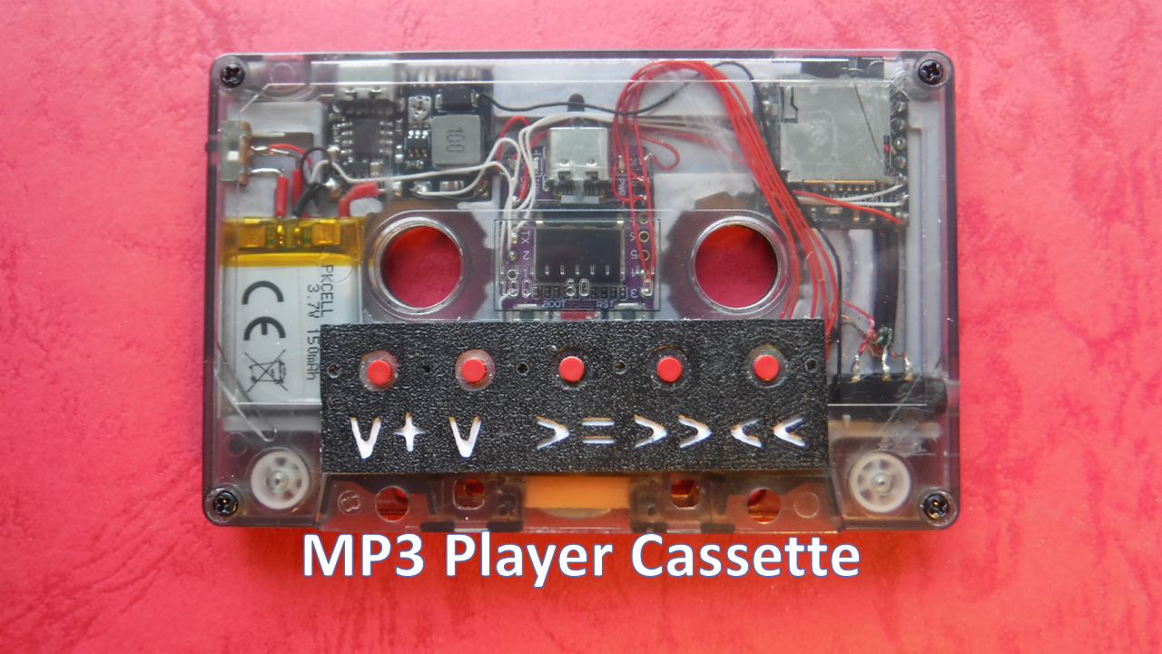
Some of us still listen to cassette tapes and it was while listening to one that this project was formed.
A quick check on the internet revealed it was not an entirely new idea but this was a while ago and such devices may prove difficult to obtain therefore I thought it would be an interesting challenge to create my own version.
A device that plays MP3 files looks like a cassette that fits into a cassette player or your pocket.
In hindsight the idea was the easy bit finding suitable sized components was a little more challenging.
Read on to find how it turned out
Supplies
Filament - PLA Silver silk
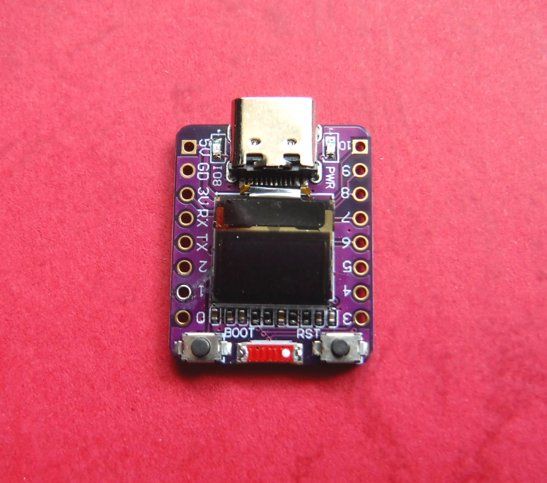
ESP32_C3 with 0.42 in OLED display
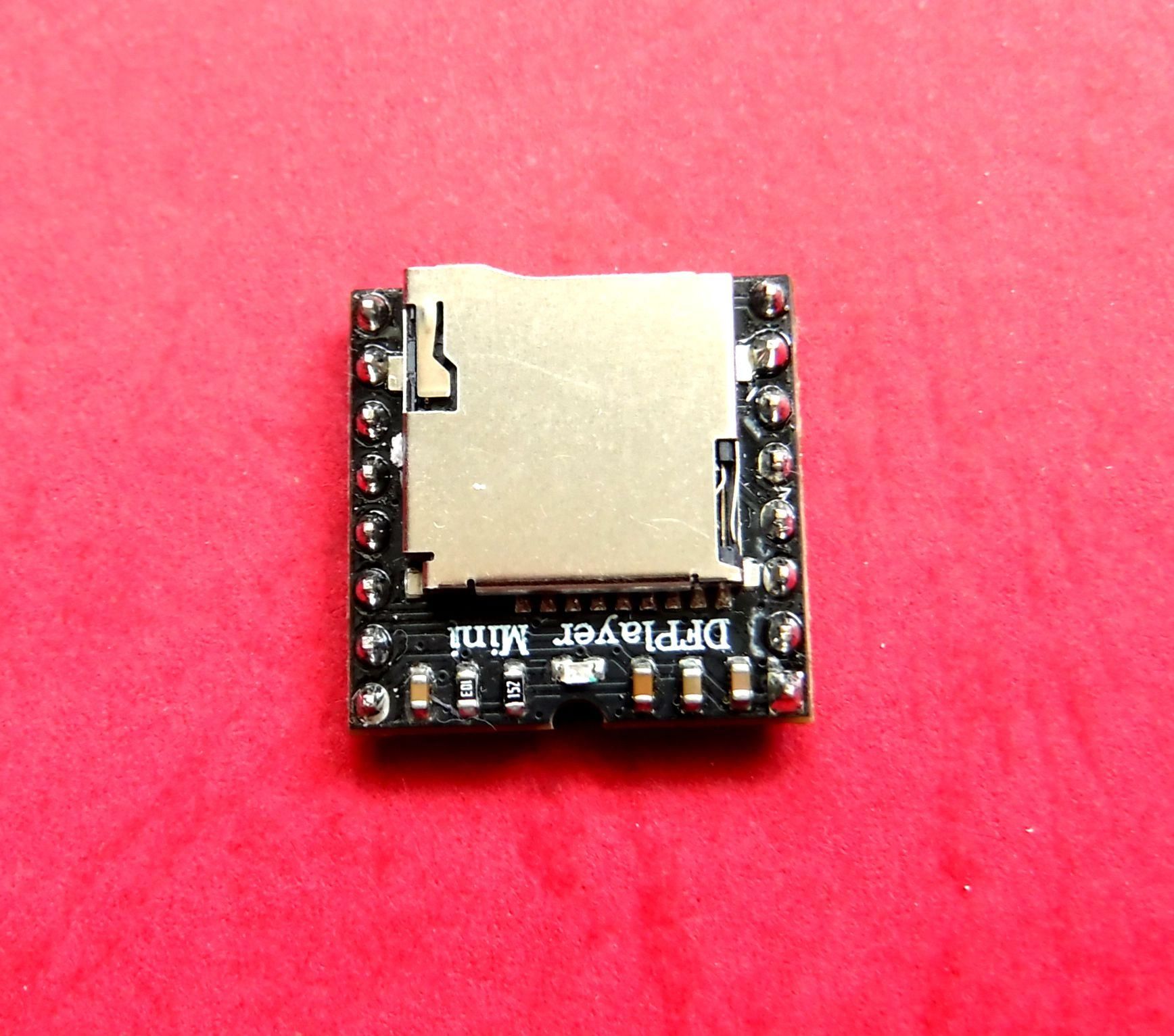
DFPlayer Mini MP3 Player
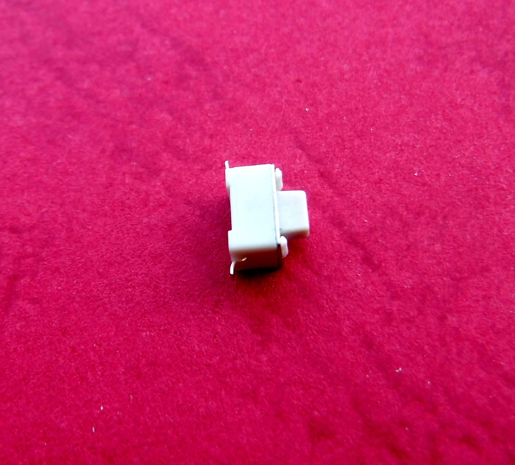
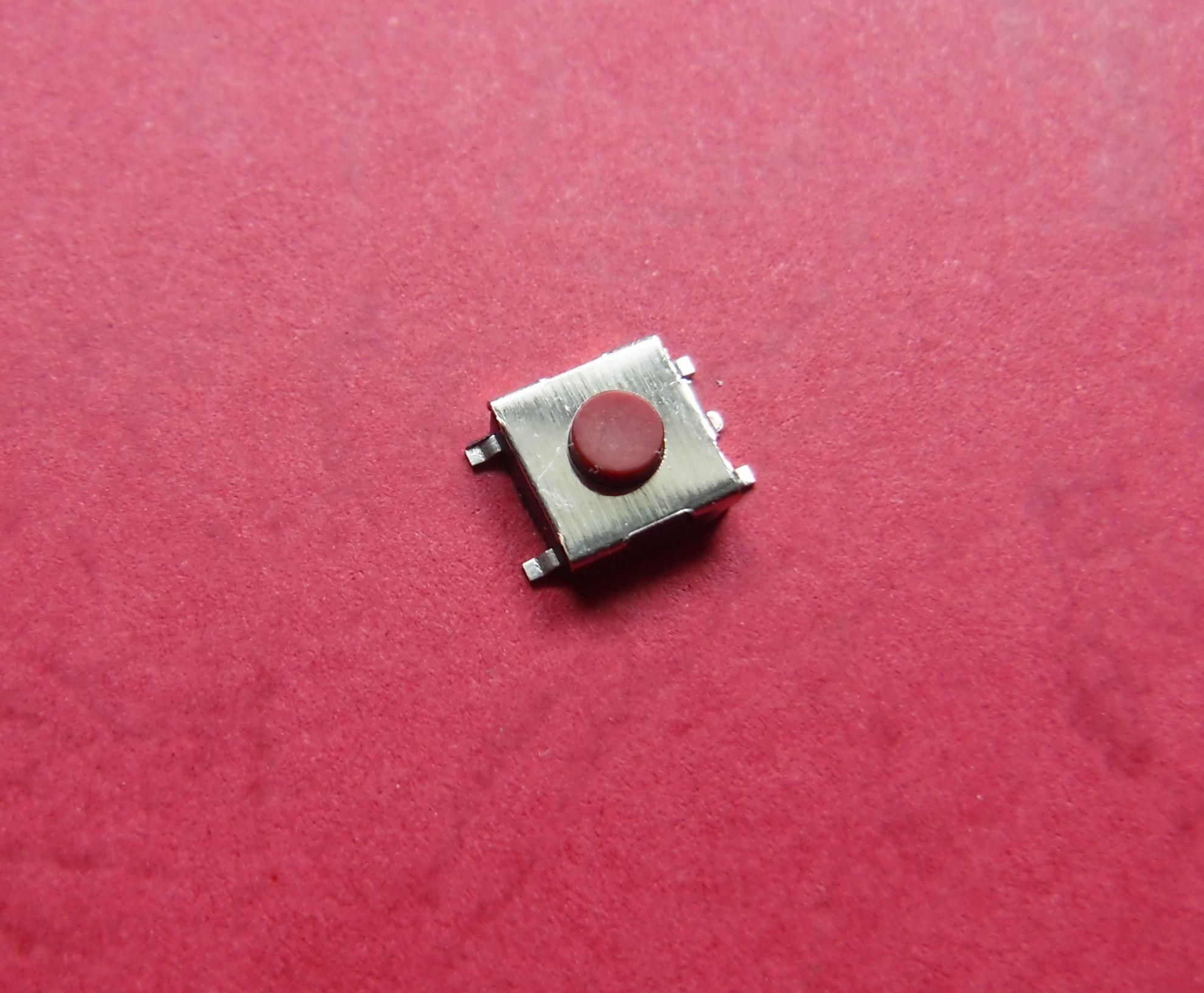
Tactile Switch 6(w) X 3.5(d) X 5(h) mm
Tactile Switch 6.2(w) x 6.2(d) x 3.2(h) mm - Qty 5
Clear Audio Cassette
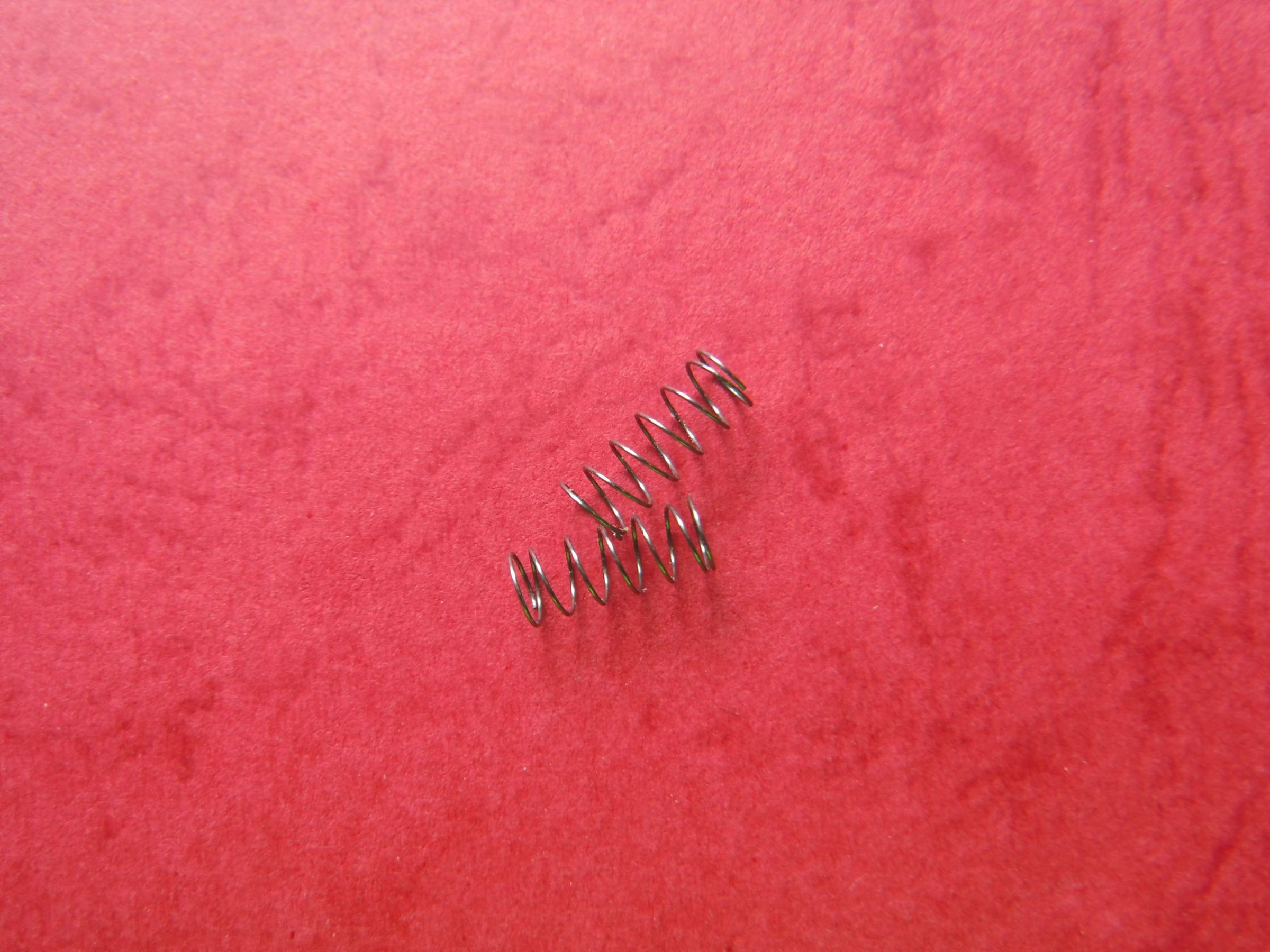
Springs 0.4(dia.) x 3(W) x 10(L) mm - Qty 2
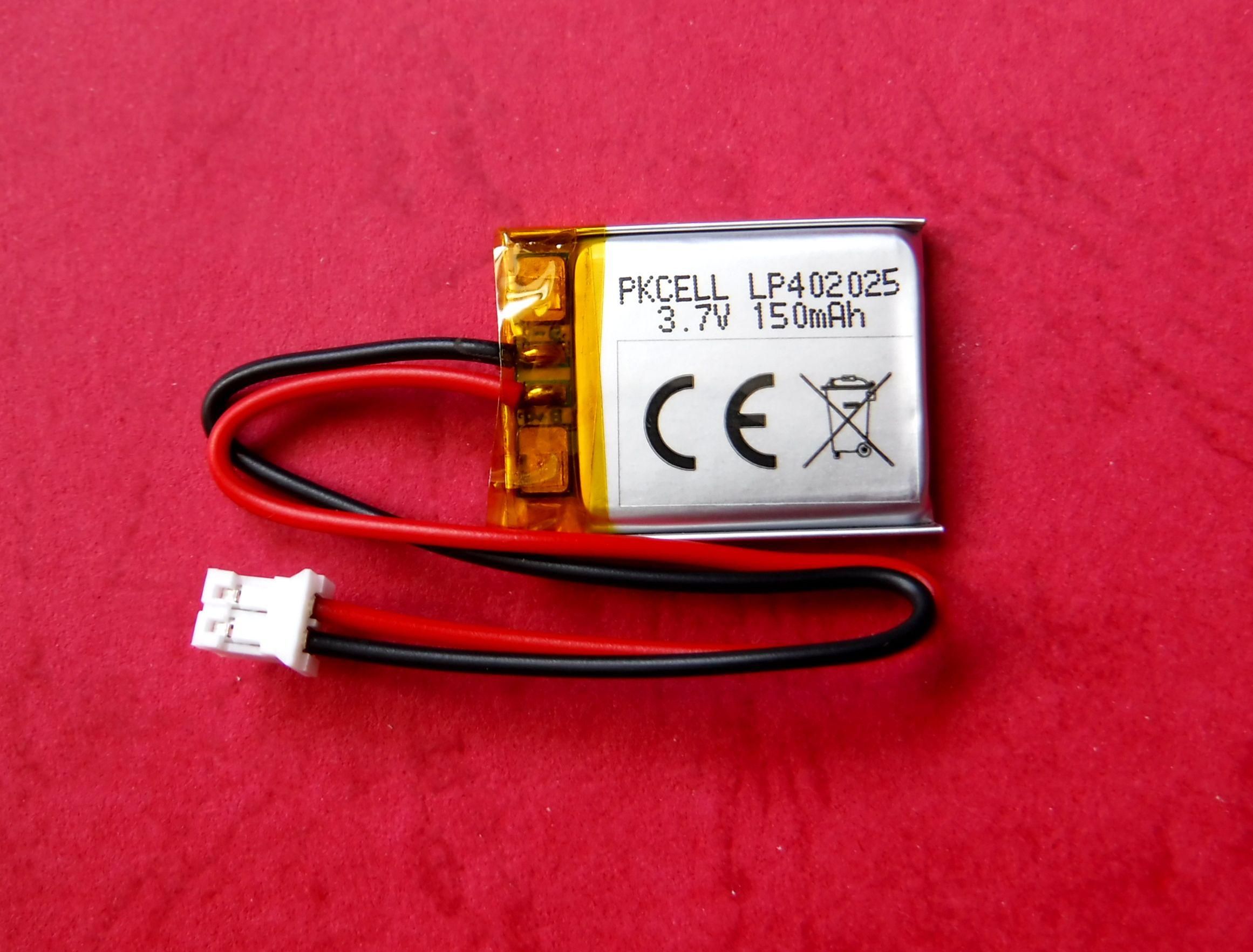
Battery LiPo 3.7V/150mA 27(L) x 20.5(W) x 4.3(T)mm
Brass Rod 1.5(dia.) x 14(L) mm - Qty 2
M2 x 3mm countersunk machine screws - Qty 4
Clear adhesive tape
Wrapping wire (30AWG single core)
100k resistor
43k resistor
Wired head/ear phones with a 3.5mm stereo plug.
May prove more cost effective to buy a range of values rather than individual values unless you already have them available. Some components may also have a MOL greater than the quantity specified in the component list.
No affiliation to any of the suppliers, feel free to obtain the supplies from your preferred supplier if applicable.
Links valid at the time of publication.
Tools
3D Printer
Rotary Burr
Small electric hand drill
Countersink drill bit
2 mm drill bit
3.5 mm drill bit
Wire Cutters
Small screwdrivers
Hard plastic glue
Soldering Iron
Solder
Needle Files
Sanding paper
Know your tools and follow the recommended operational procedures and be sure to wear the appropriate PPE.
Cassette Case
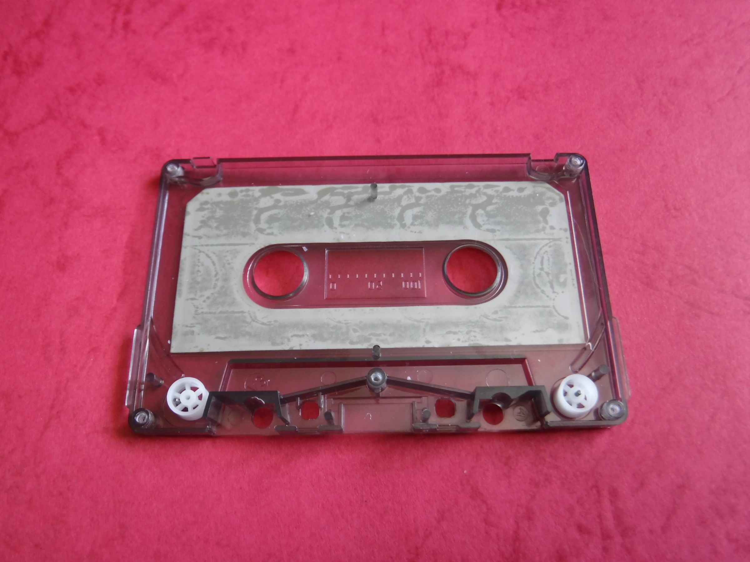
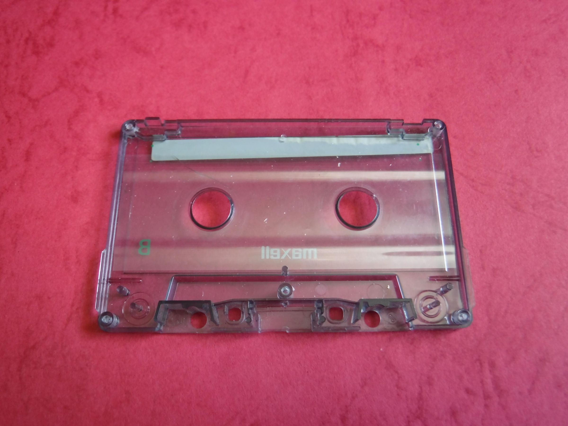
The first step was to dismantle a couple of different cassette tapes to determine the space available taking into account any clips, lugs or partitions that are integral to case assemble and may also affect positioning on the elements to be added.
Clear tape cassettes were chosen as a display would be incorporated to enable tracks and status to be displayed.
Cassettes with mainly opaque bodies with a clear centre window could be used but I did not have one to hand at the time. They also do not appear to be in ready supply compared to the all clear version.
However, if all you have is an opaque cassette it is possible to cut out a central opening and stick a clear PET film over the opening.
I would ensure no elements extended in the area on the left hand top corner where the record enable/disable pin could enter.
Other areas off limits are the capstan holes and the front section where the tape head would sit.
All elements would be limited to a maximum height of 5mm.
Component Choice

Any chosen elements are constrained by a 5mm height and in addition the smaller their area the better.
Due to the internal constrains the number of elements needed to be as few as possible.
These are the main elements chosen although smaller elements may well exist.
1: A microcontroller with an integrated screen (ESP32_C3, size: 20(w) x25(l) mm)
The size of the screen (0.42inch/10.7mm), limits the display to basic information but given that the DFPlayer constrains tracks name to numbers this is not seen as a significant issue. It small size also offers some protection encapsulated within the cassette.
The ESP32_C3 supports BLE not BT Classic negating streaming to wireless headphones.
2: Rechargeable battery. (3.7V/150mA LiPo, size: 20.5(w) x 27(l) mm)
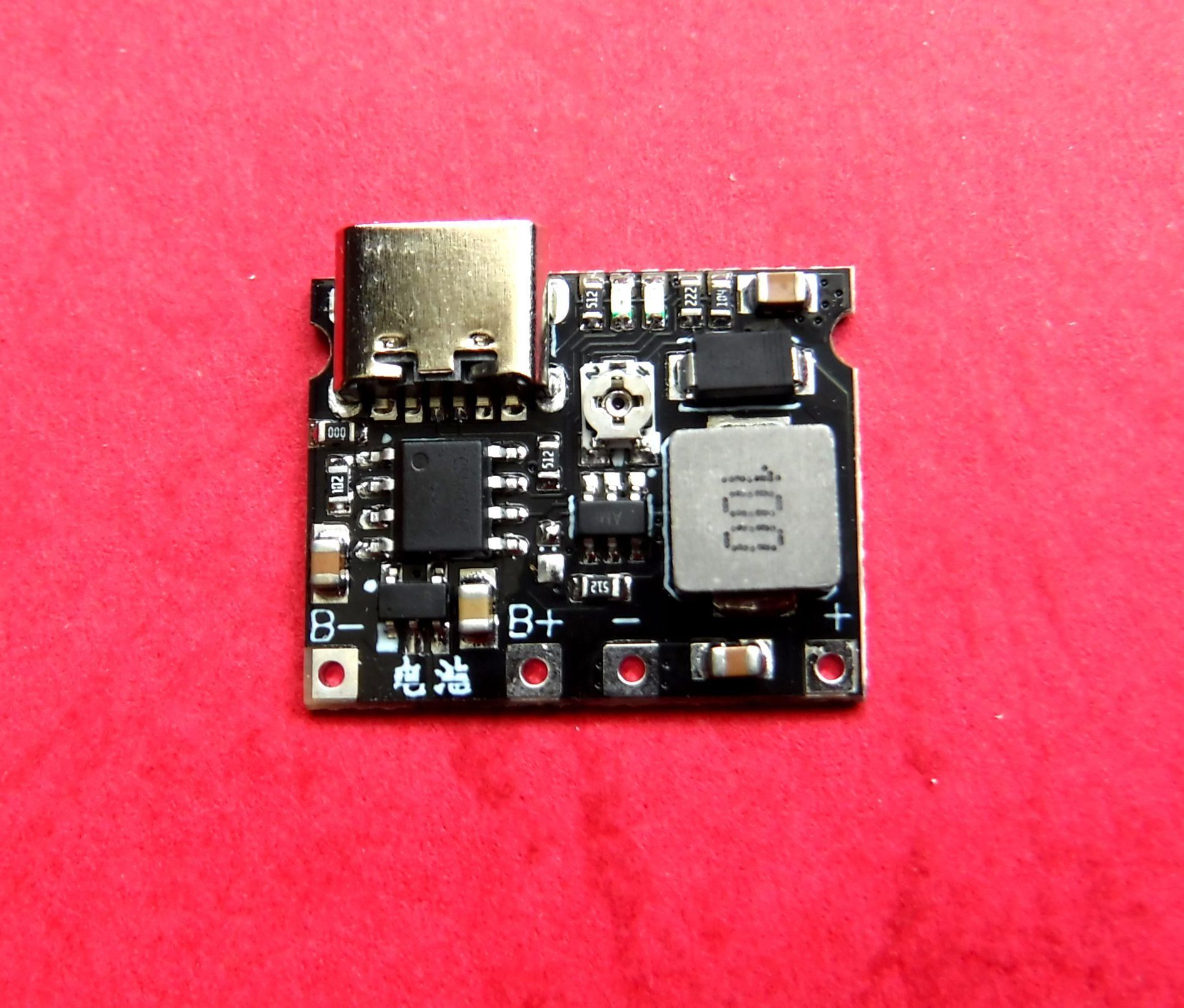
3: Integrated battery charger/booster. (size: 24(w) x 19(l) mm)
4: Mini MP3 player module. (DFPlayer mini, size: 20.32(w) x 20.32(l) mm), came supplied with header pins which required cutting down. A solid state version exists but this has a larger footprint and less memory and was therefore not used.
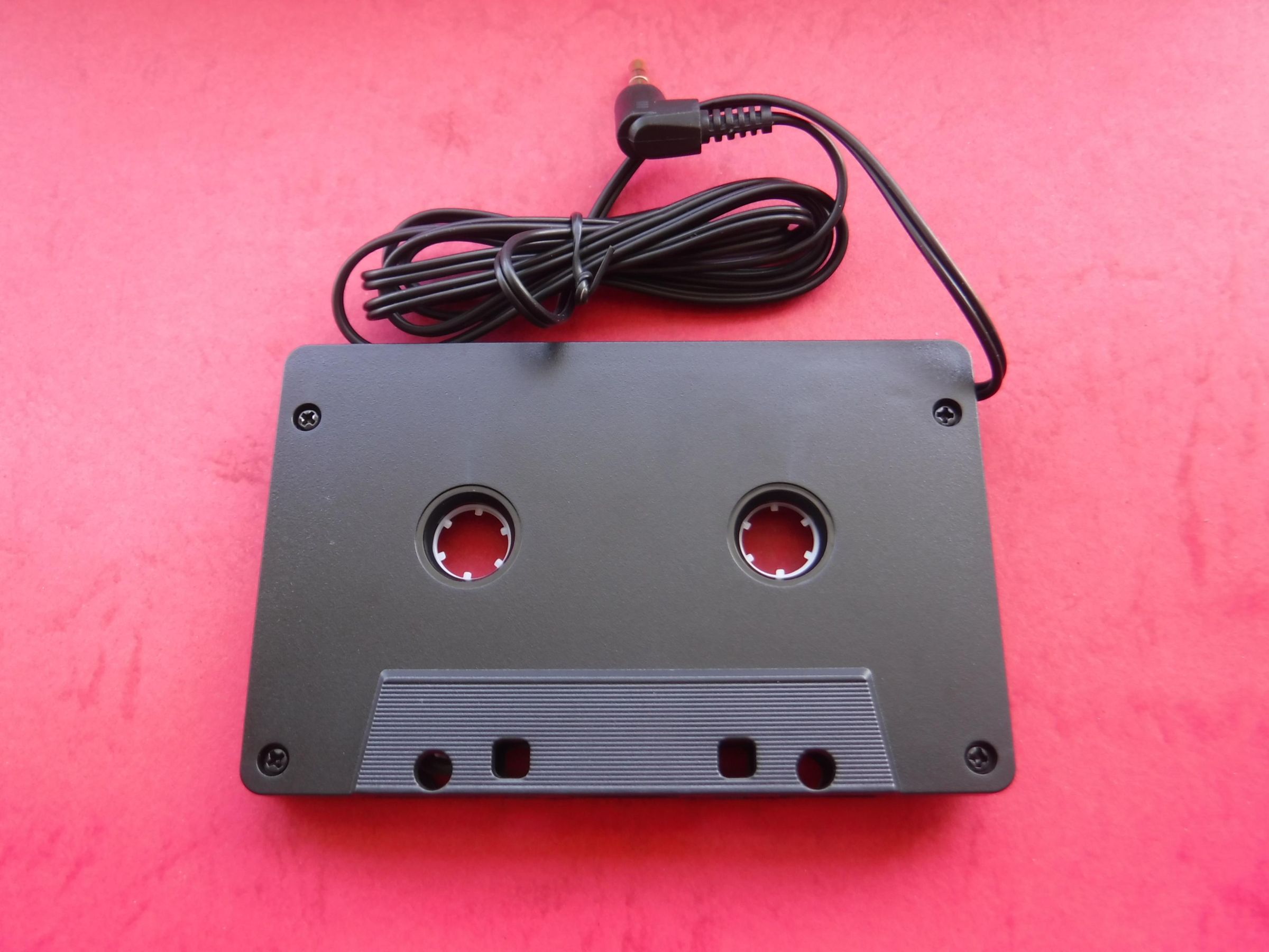
5: Tape head (removed from a multi cassette adapter)
Additional smaller components.
Switches, headphone socket.
Once the main elements have been selected these need to be positioned within the limited space and any access ports positioned at the perimeter.
Charging access for the battery charger/booster.
Access slot for the micro SD card of the MP3 module.
Power switch and Headphone socket.
The screen needs to be visible when the cassette is in the player and this is best centrally positioned between the reels in line with the window in the player door/flap. Although, unfortunately some players do not have a widow in the door.
Low profile tactile switches can be mounted on the larger external surfaces.
Circuit
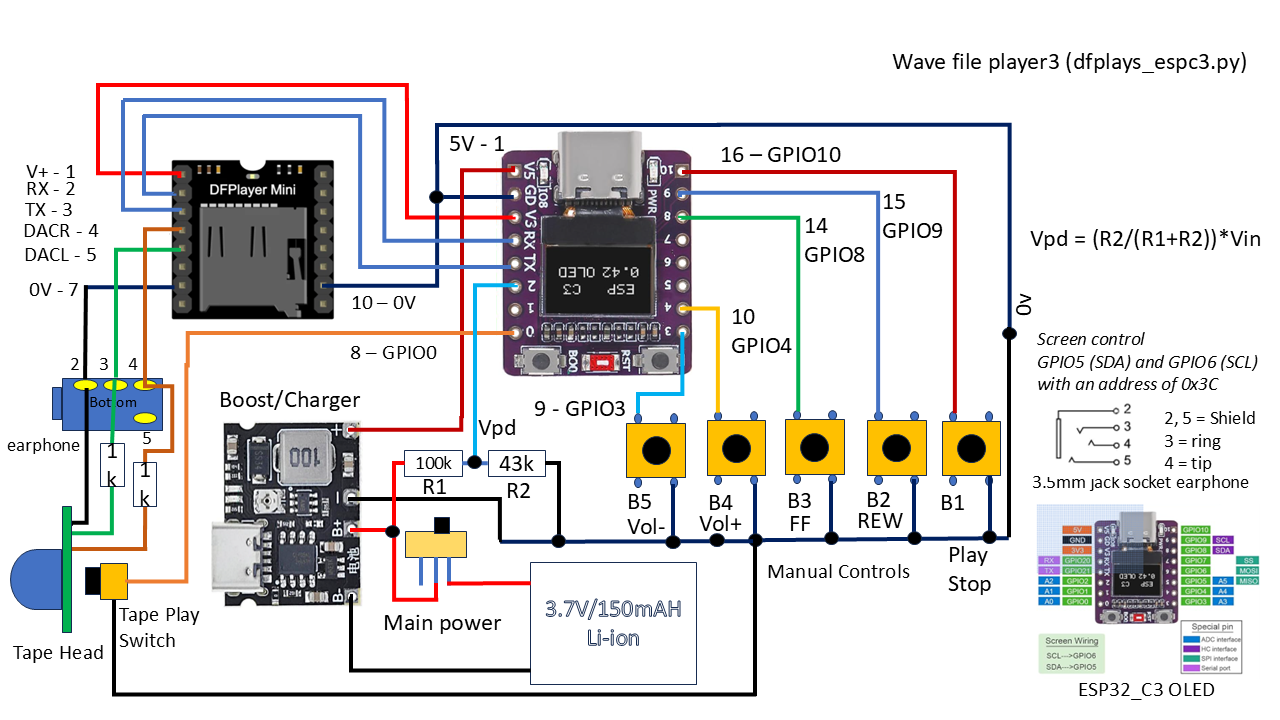
The circuit consists of an ESP2_C3 mini with integrated OLED display programmed in MicroPython.
This is a small footprint microcontroller with 16 accessible pads.
See attached diagram and details below.
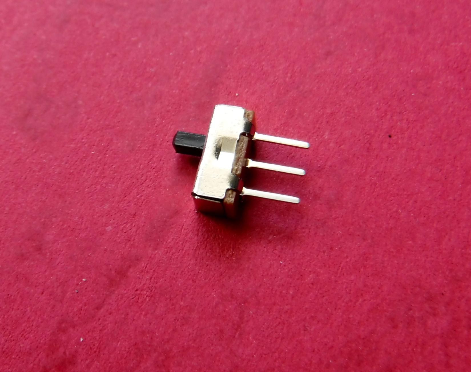
Power is provided by a rechargeable LiPo 3.7V/150mAh battery connected via a slide switch to B+ (battery -Ve to B-), on the boost/charger which provides 5V to the VBUS pin (1).
A potential divider consisting of two series resistors are connected across the battery when the power switch is activated and used to monitor the battery voltage. (See Battery Monitor step)
The output from the ESP32_C3 3V3 pin (3) is connected to the DFPlayer supply pin (1).
From the ESP32_C3 pins 4 (RX) & 5 (TX) are cross connected to the DFPlayer at pins 2 (RX) & 3 (TX).
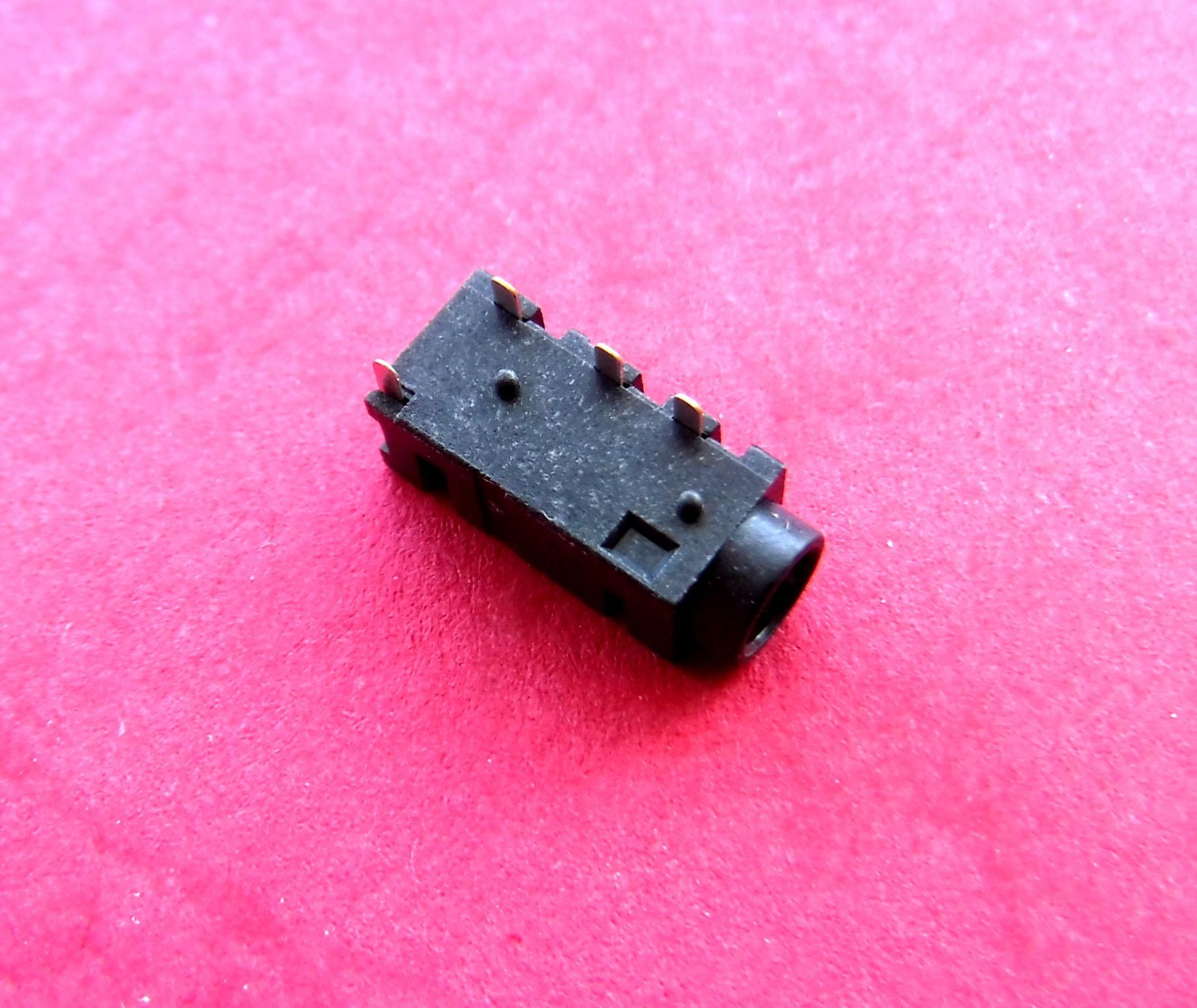
The output from the DFPlayer pins 4 (DACR), 5 (DACL) and 7 (OV) are connected to the earphone socket pins 4 (Tip), 3 (Ring) and 2 (Shield).
The Tape head inputs have serial 1kR resistors and are also connected to the earphone socket at pins 2, 3 & 4,
A switch is mounted behind the Tape head which initiates play when the mechanical play button is pressed this switch is connected to ESP32_C3 pin 8 (GPIO 0)
The user controls are connected with internal pullups (resistor from pin to 3.3V), to pins 9 (GPIO3) [VOL-], 10 (GPIO4) [VOL+], 14 (GPIO8) [FF], 15 (GPIO9) [REW] & 16 (GPOI10) [Play/Stop] via switches to OV.
The 0V line connects to -Ve on the charger/booster, the switches, pin 2 on the ESCC3, Pins 7 & 10 on the DFPlayer, pin 2 on the earphone socket and to the Tape Head
Battery Monitor
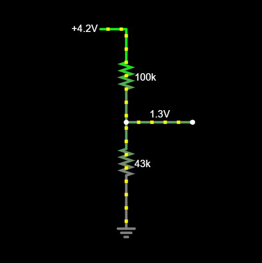
The battery voltage is monitored using a potential divider consisting of two resistors (R1 = 100kR and R2 = 43kR), in series.
This is connect across the battery when the power switch is closed.
The potential divider ratio is 0.301 this multiplied by the applied battery voltage (Vbat), gives the centre tap voltage (Vct), for the resistor network. This is applied to the ESP32_C3 pin 6 (GPIO 2)
Vct = (R2/(R1+R2)) * Vbat
The potential divider ensures the voltage applied to the GPIO pin is considerably less than the absolute maximum of 3.6V.
In this case even if the potential divider is connected to 5V, Vct = 1.5V
The battery charge, discharge cut offs and nominal voltage specs are 4.2V, 3V and 3.7V
Current drain on the battery of 29.4uA = Vcharge/(R1+R2) = (4.2V/143kR), plus additional pin leakage (<50nA).
These values yield Vct voltages of 1.26V, 0.902V and 1.11V which are catered for by ADC_6db attenuation with a linear range of 0mV to 1300mV. Reference ESP32_C3 Datasheet
The actual value will likely differ from the calculated values due to component tolerance, non linearity, noise, drift and other variances.
These effects can be compensated for with filtering, calibration, tight tolerance components, entering numerical values for calculations that match actual values but always verify the results against a reference to assess the offset.
A moving average filter is applied to the raw data.
Subject to variation a 100nF MLCC (Multilayer ceramic capacitor), can be connected between the ADC input and 0V
Use 1% or better and SMD resistors due to the small space.
Confine voltages within the linear range of the ADC.
However, the monitor will not be displaying the voltage but a percentage of charge based on the charge and discharge cut off limits using the following:
Vpct = int(((vf - Vpd_min) / (Vpd_max - Vpd_min)) * 100)
where
vf = round(((adcval / 65535.0 * 1.6) - Verr),2)
(adcval = moving average value, 65535 due to using adc.read_u16, attenuation = 1.6, Verr is offset correction.)
Rratio = R2/(R1+R2) = 43k/(100k +43k) = 43k/143k = 0.301
Vpd_max = round(bat_max*Rratio,2) = 1.26V if bat_max = 4.2V
Vpd_min = round(bat_min*Rratio,2) = 0.902V if bat_min = 3V
Therefore, if the battery voltage = 3.7V, vf = 1.11V
Vpct = int(((1.11 -0.902)/(1.26 - 0.902)) * 100) = 58%,
A variation of 10mV equates to 2.8%.
Retainer
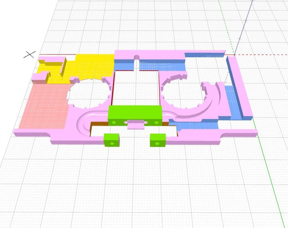
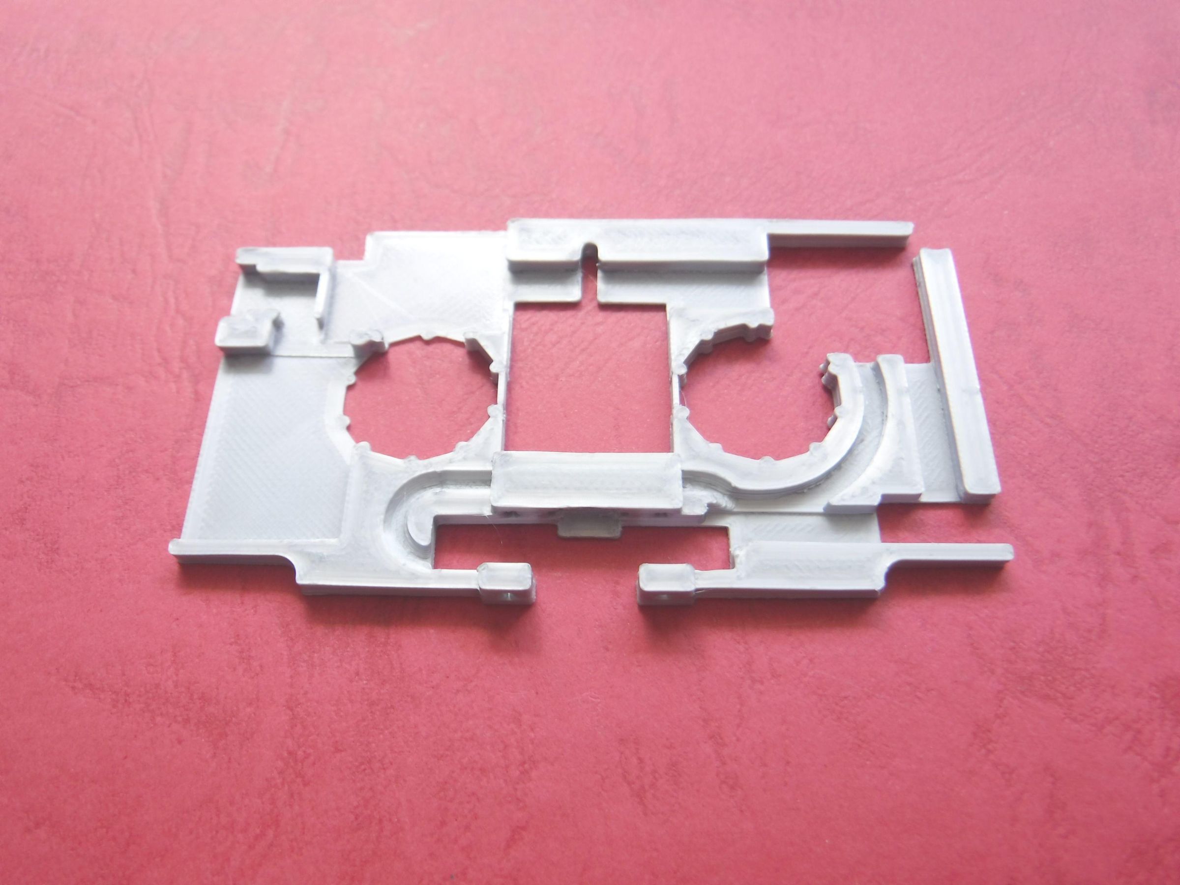
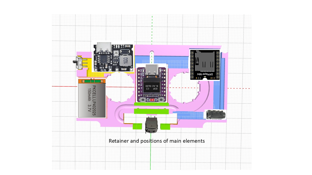
I originally considered a PCB to connect and retain the main elements in position within the cassette but as the main elements were stand alone modules, rather than individual components only simple point to point wiring was used to connect them together. A PCB would be a consideration for a future version.
As a result of using modules I decided to make a 3D printed retainer.
The retainer fits within the cassette with compartments to retain the main elements in place with routing channels for the interconnecting wiring.
Open areas were left under the MP3 module and the microcontroller as these did not compromise the integrity of the retainer any additional material under these elements would impact closure.
Under the areas upon which the charger/booster and battery sat a thin layer (<=0.2mm), of material was added to maintain structural integrity whilst not impacting closure.
Print Details:
Filament: PLA Silver Silk
Layer Height: 0.1mm
Infill: 100%
Build Adhesion: Skirt
A silk filament was chosen in preference to a more rigid filament as it had a little more tolerance to variation in the elements and fit within the cassette body.
Post processing
The extreme edges of the retainer may need to to sanded smooth to ensure a fit into the cassette body.
Downloads
Cassette Spool
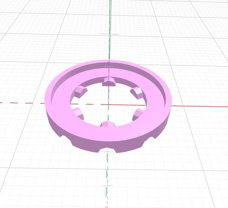
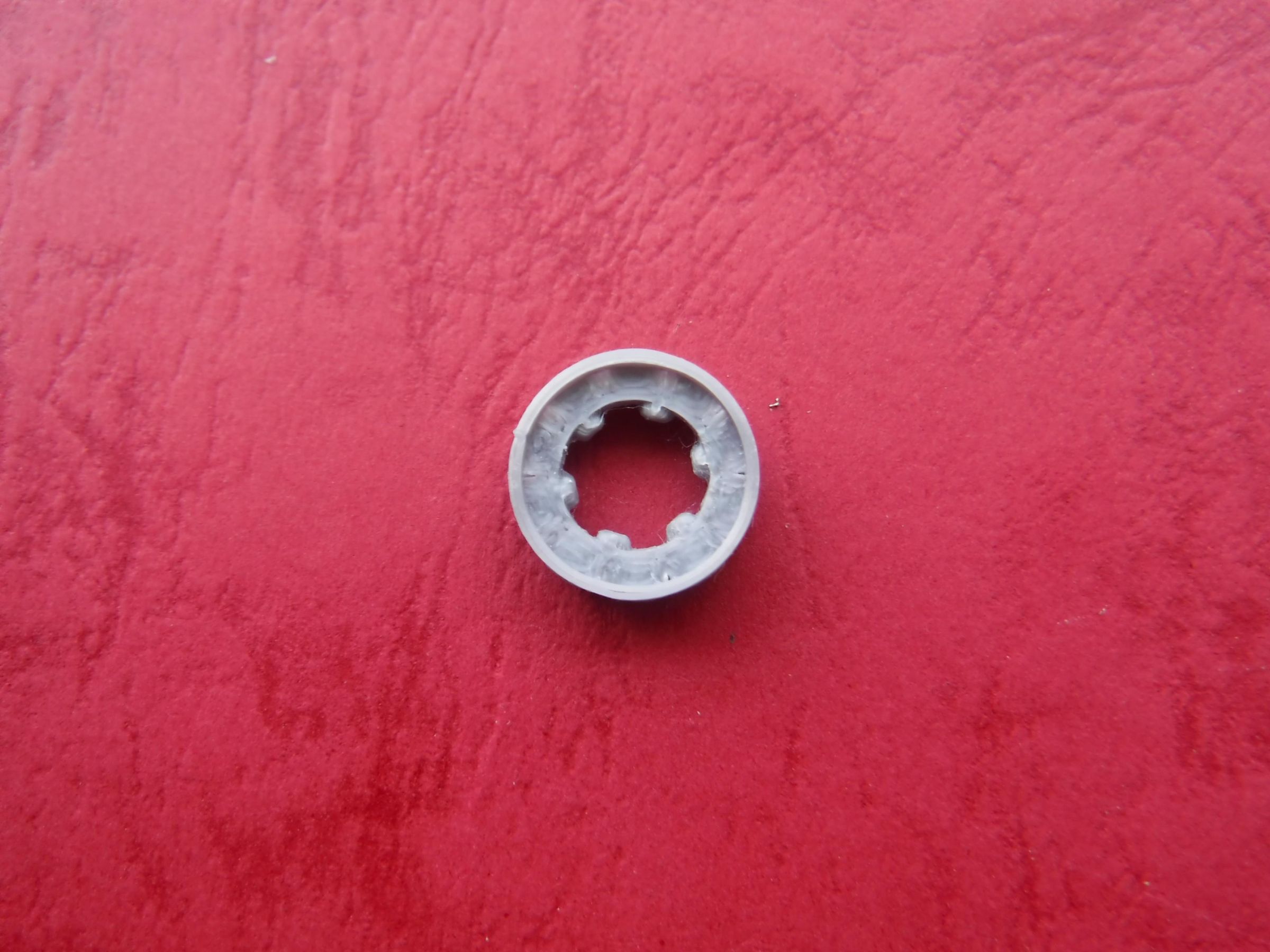
I have included the spools as the original intention was to include these within the cassette for completeness although this was cosmetic rather then functional.
However, the position of the DFPlayer lower left hand corner protruded into the area and in conjunction with wire routing would compromise rotation therefore I omitted the right hand spool.
Moving the DFPlayer back towards the edge results in the SDcard protruding beyond the cassette which depending on the player prevents closure or impacts connectivity of the SDcard as the cassette is pushed back when the play button is pressed. Hence the DFPlayer's current position set back from the edge.
Having omitted the right hand spool I felt having only one spool would create a visual imbalance and therefore omitted the left hand spool.
Printing and assembly
The cassette spool consists of two halves which once printed are stuck together.
Its printed as two halves as a lip is required on both sides to retain it between the two halves of the cassette.
Two completed spools are required.
Print details
Filament: PLA Silver Silk
Layer Height: 0.1mm
Infill: 100%
Build Adhesion: Skirt
Post processing
Lightly sand the base of the spools and clean with IPA and allow to dry.
Ensure the cut outs on the outer circumference of the spool and the inner teeth align.
Apply a plastic adhesive and allow to dry.
Ensure the inner surface of the spool is clear of aberrations that may prevent the sprockets in the player fitting using a needle file.
Downloads
Centring Frame
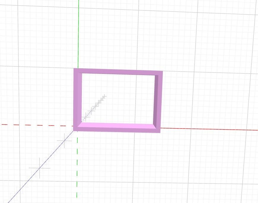
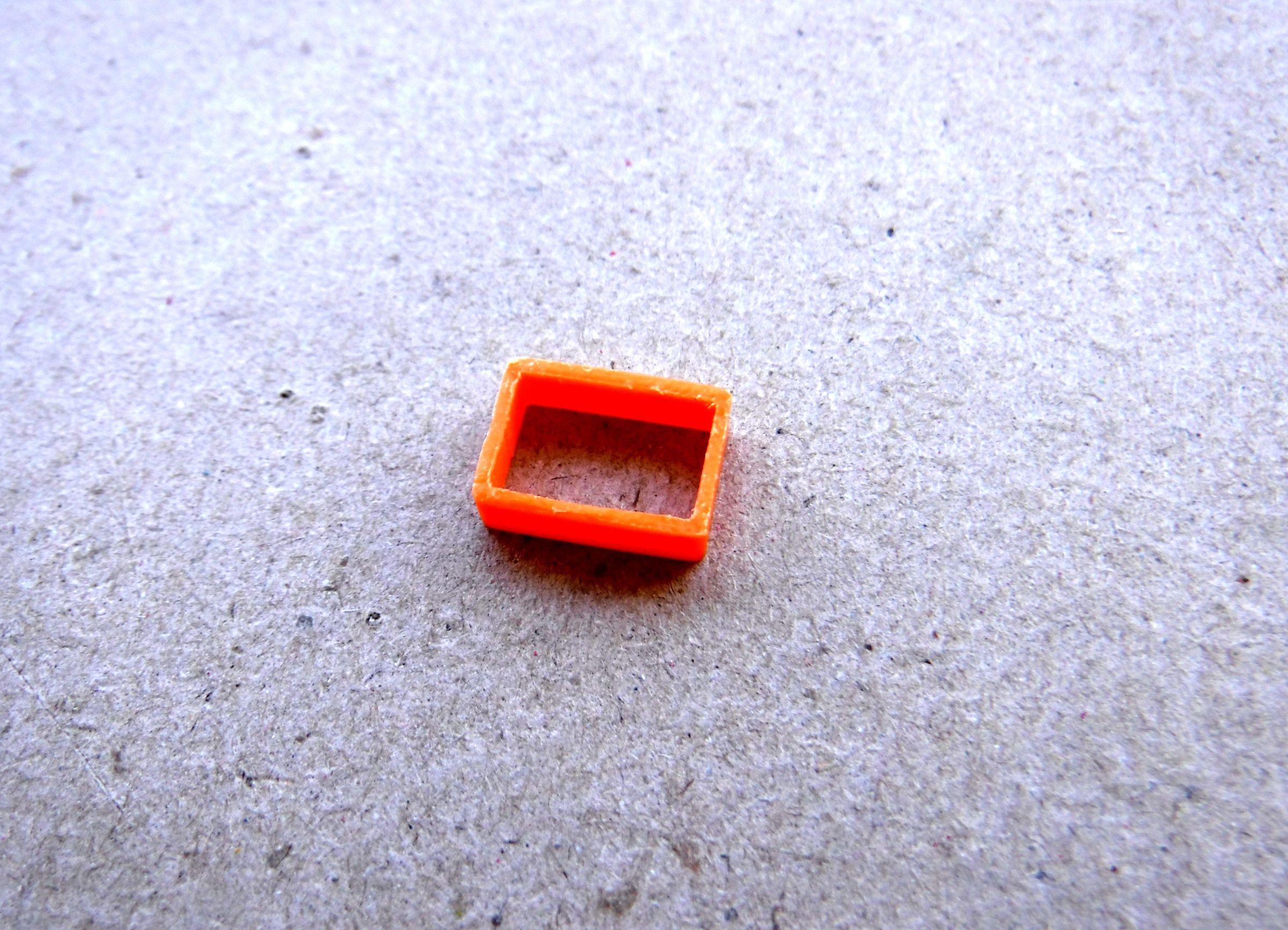
The centring frame is used to align the tape heads between the cassette and the player.
Once assembly is complete this is fitted by simply sliding over the tape head.
Dimensions
Outer: 13.875(w) x 9.875(h) x 4(d) mm
Inner: 12.5(w) x 5.5(h) x 4(d) mm
Print Details
Filament: PLA Orange
Layer Height: 0.1mm
Infill: 100%
Build Adhesion: Skirt
Post Processing
There may be a lip on the inner and outer edges at the surface in contact with the print bed.
With a needle file remove the lip to level the sides.
Downloads
Cassette Modification
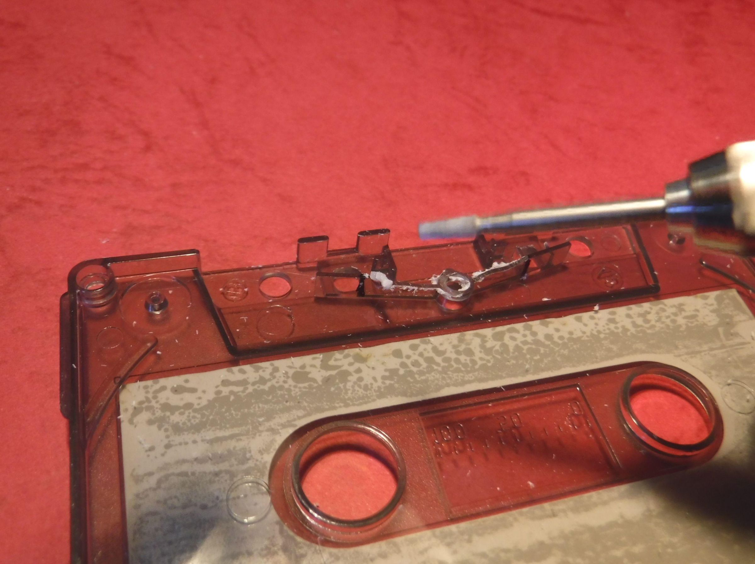
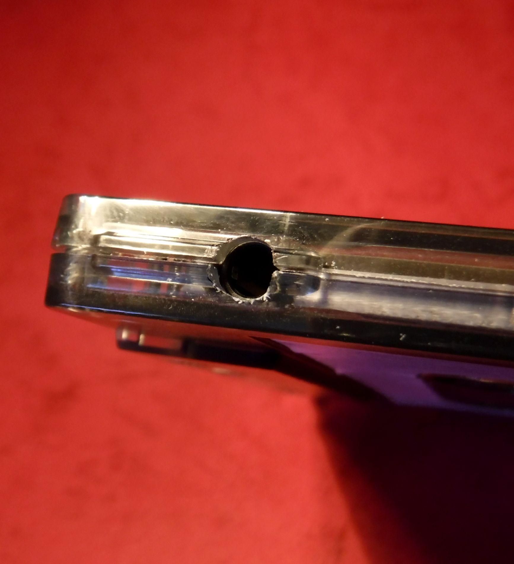
Modifications are required to the cassette to accept a number of the main elements.
These are for the:
1: Retainer.
2: USB C socket.
3: MP3 module micro SD card slot
4: Power switch
5: Headphone socket
All these elements require modification to both sides of the cassette.
Use the retainer to seat the elements in place.
Mark the area to be removed with a permanent ink pen using the outline of the element as a guide.
The areas to be modified can be accomplished using a small rotary burr mounted to a small electric hand drill or larger drill with a flexy drive attachment.
Following this any fine tuning can be accomplished with needle files.
Tape Head
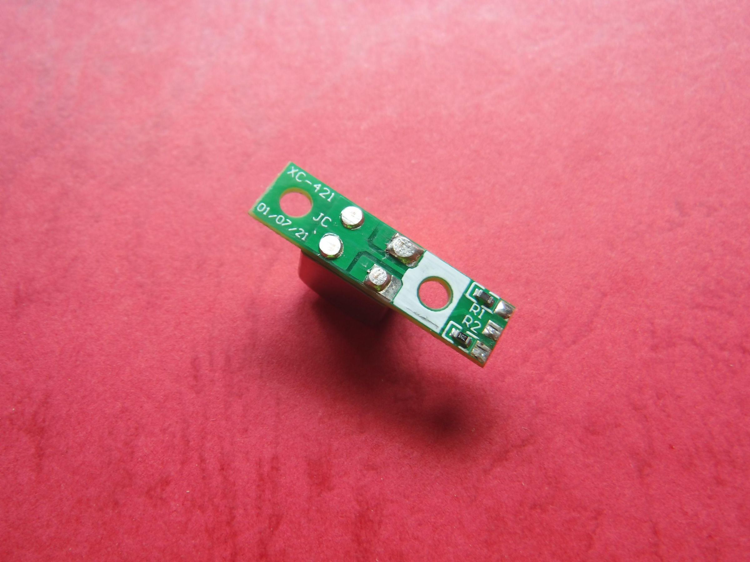
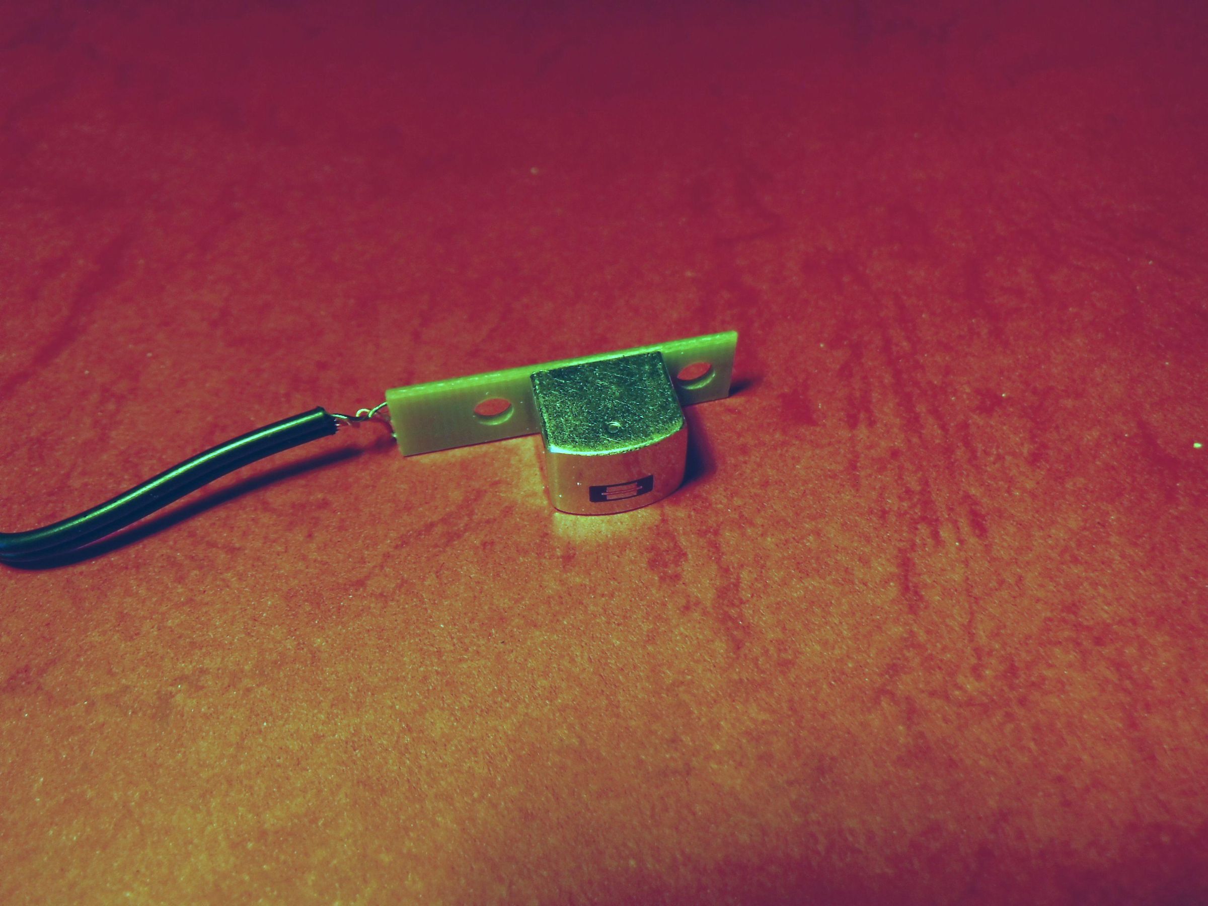
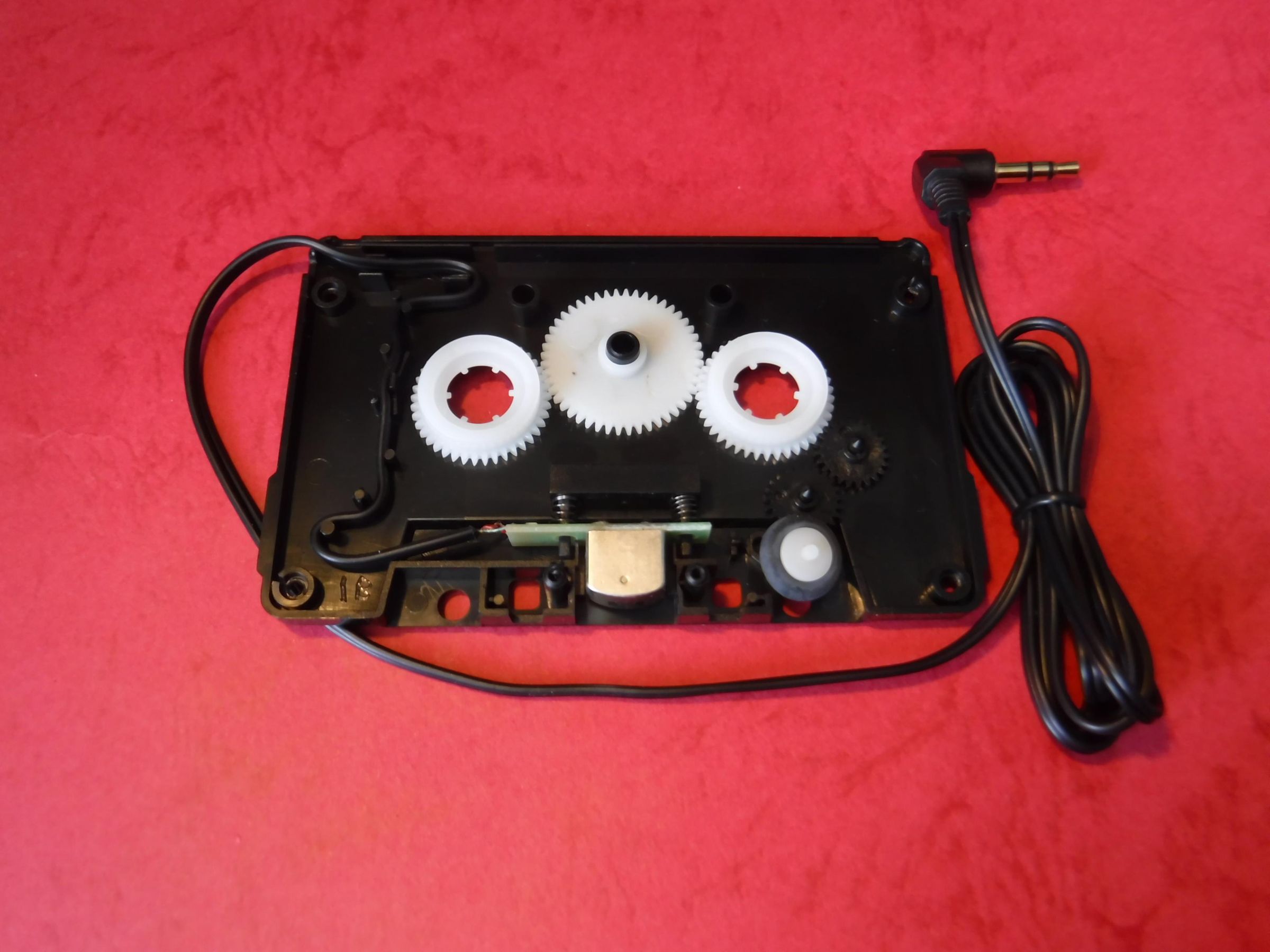
The tape head was removed from a multi cassette adapter.
Alternatives are one from an old tape machine or purchasing individual heads.
If you use a different cassette adapter it may result in a different removal method and/or an incompatible fixing.
I did consider using this cassette to house the main elements for this project. However, it did not have a clear body. Not a show stopper but would require a different approach to the one taken.
Hence it was not used in this project.
The tape head is connected via signal limiting 1K resistors and a small PCB to a lead which at the end has a 3.5 mm jack plug.
Once removed from the case most of the lead connected to the jack plug would be cut off, leaving a short length connected to the tape head PCB.
The two springs would also be used in the project.
However, in the event that a spring or springs gets lost alternatives are listed in the supplies.
Removal of the tape head is straight forward.
The spring retainer is a friction fit and can simply be removed by pulling it out with small pliers, taking care not to lose the springs.
Ensure that the solder connections on the tape head PCB are filed level but still slightly raise by ~1mm so as to retail structural integrity whilst maintaining the electrical connection.
Switch Cover
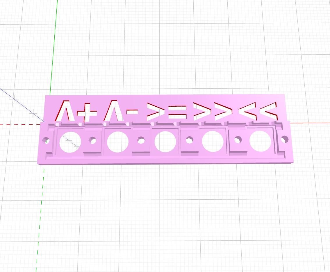
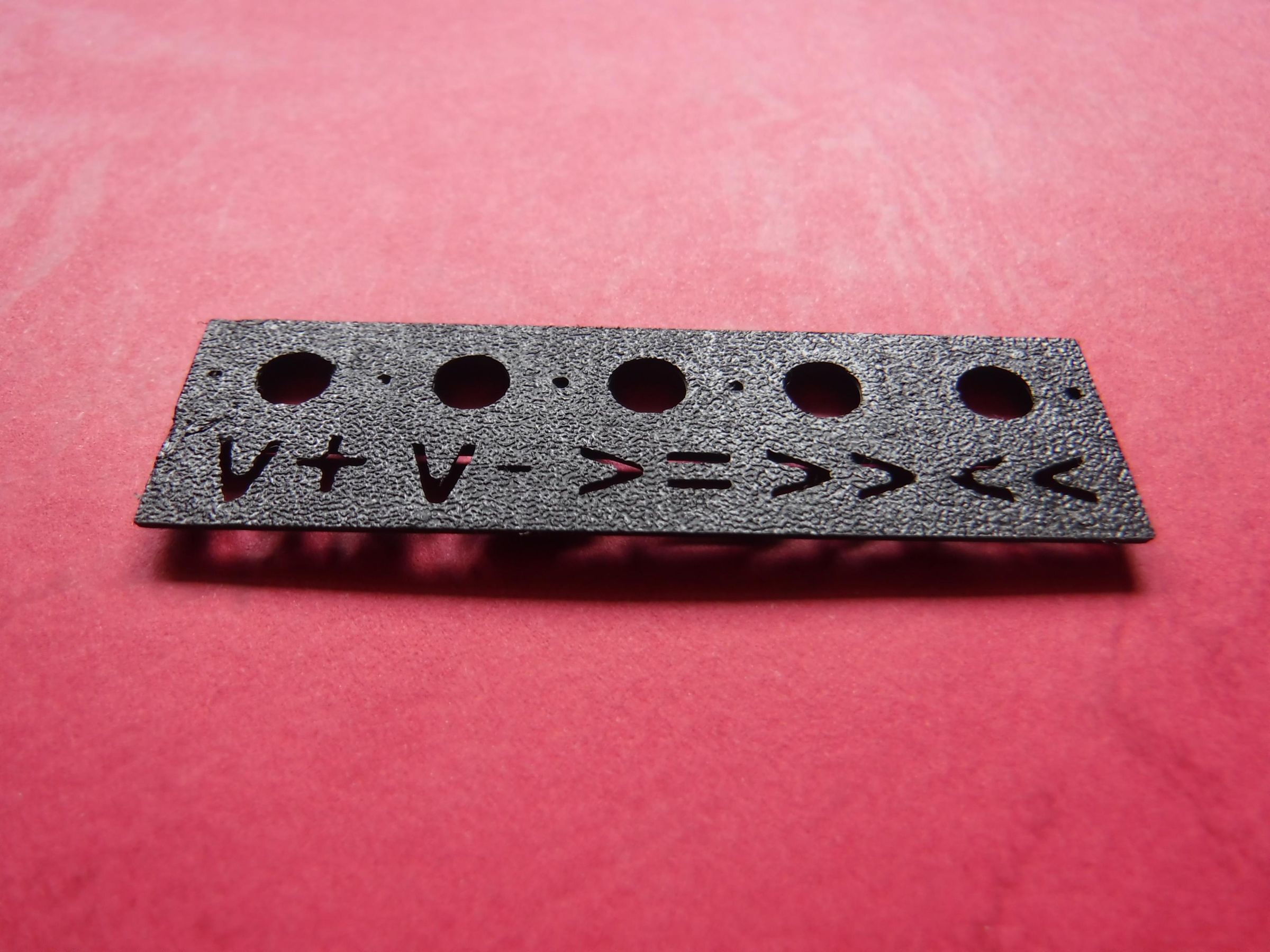
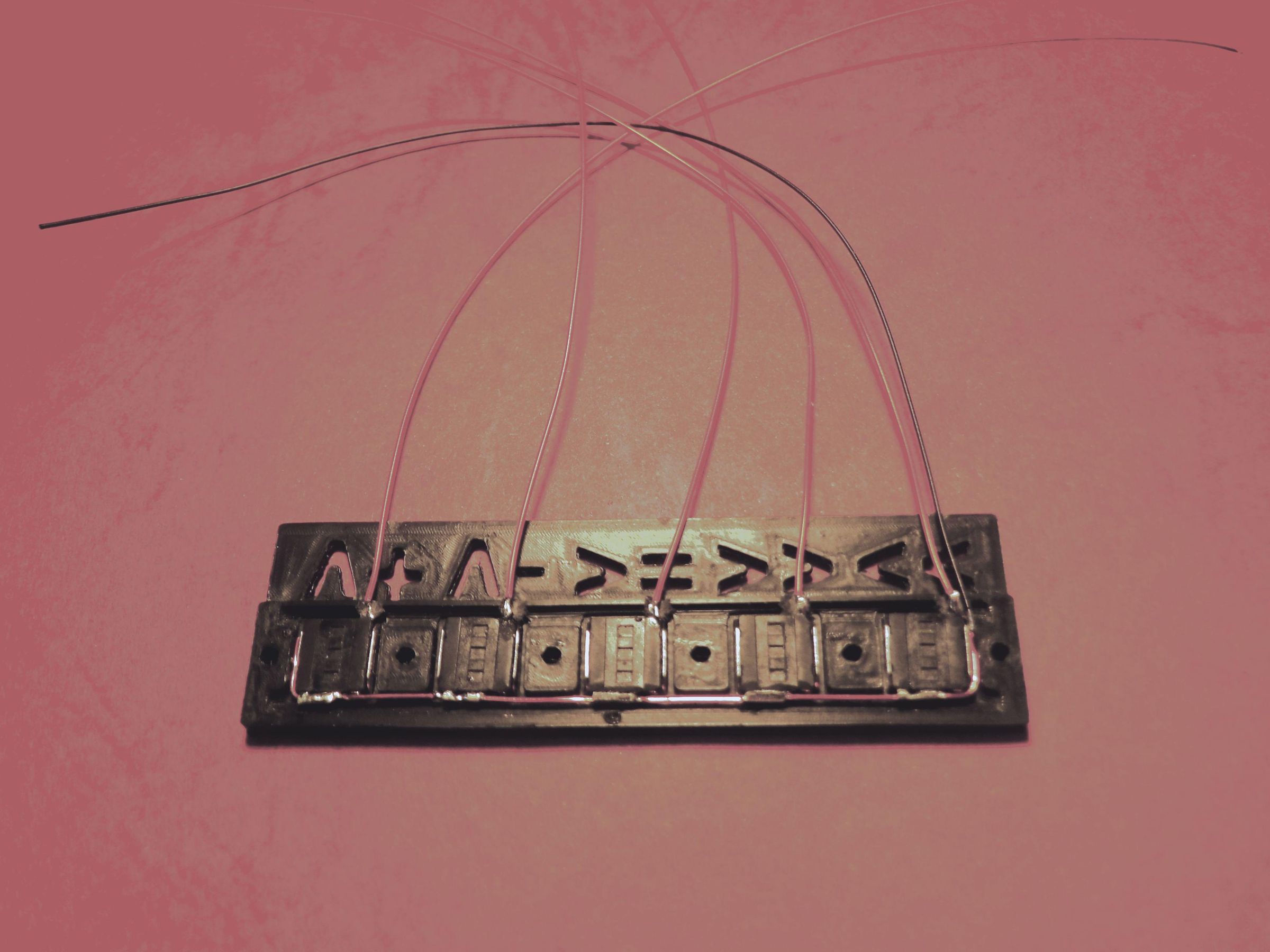
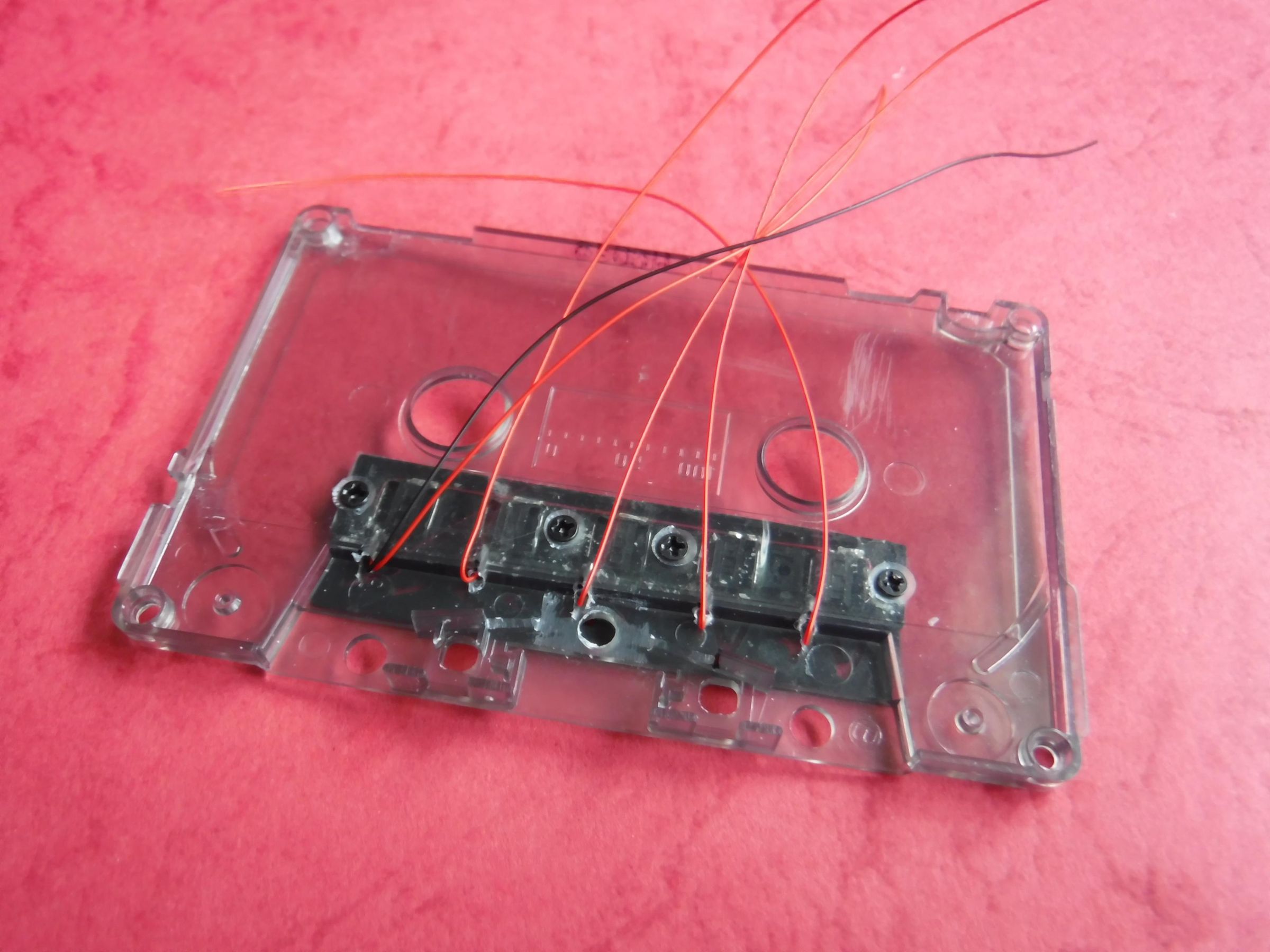
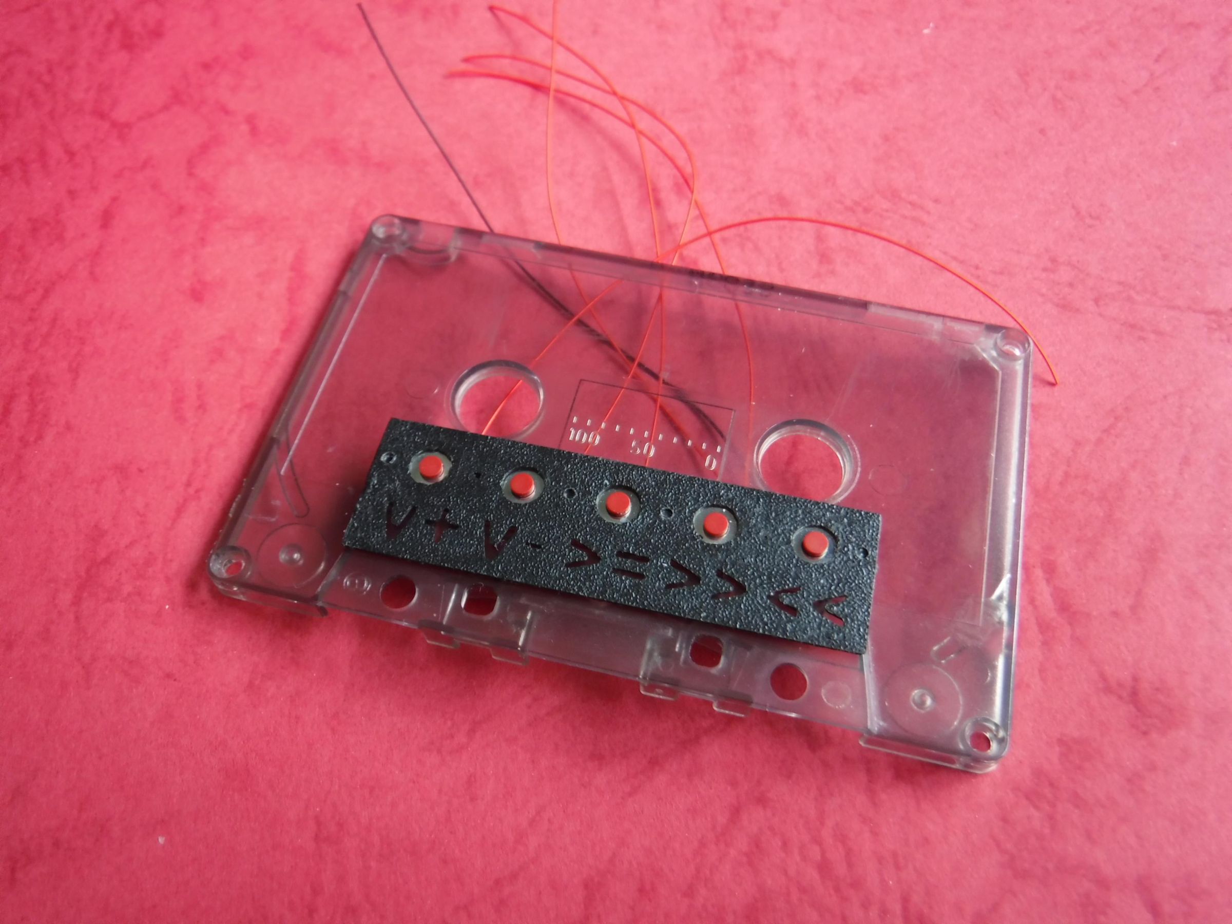
The buttons are mounted on the exterior of the case in a 3D printed cover.
Print Details:
Filament: Black PLA
Layer Height: 0.1mm
Infill: 100%
Build Adhesion: Skirt
Dimensions: 65(l) x 19(w) x 2.5(h) mm
Post Processing
Smooth the edges with sanding paper if necessary to remove any irregularities
Assembly
Five tactile switches are required to control the player.
The functions are annotated with a letter and/or with symbols.
1: V+ - Increase Volume
2: V- - Decrease Volume
3: >= - play/stop
4: >> - Fast Forward
5: << - Rewind
Arranged left to right in the order listed above.
The switch cover is designed with pockets within which sit the tactile switches.
A single enamelled coated wire {ECW), connects the same terminals of all the other switches together and this wire becomes the common switch terminal.
Single wires connect the remaining terminal switches to the microcontroller.
Once all the switches are wired and aligned in the pockets a strip of clear tape is used to keep the switches in place and attached to the cover.
The switch cover with switches is mounted on the front of the cassette body using 4 x M2 x 3mm countersunk screws.
Align the switch cover such that its step meets with the step in the cassette body and fix in position with tape and with a small drill bit or awl mark 4 holes, the two ends and the two centre of the retainer.
On the inner part of the cassette mark the position of the wires from the switches.
Drill 9 x 2mm holes and countersink the inner surface of the cassette body for the 4 holes that will secure the retainer.
Feed one wire of each switch through each of its associated holes and secure the retainer in place with 4 x M2 x 3mm countersink machine screws.
Run the wires parallel to each other and coincident with the step and tape in place.
In order to improve legibility of the symbols on the switch cover a slip of paper can be placed under the gap between the switch cover and the cassette body, white or a fluorescent yellow are ideal.
Downloads
Tape Head Switch
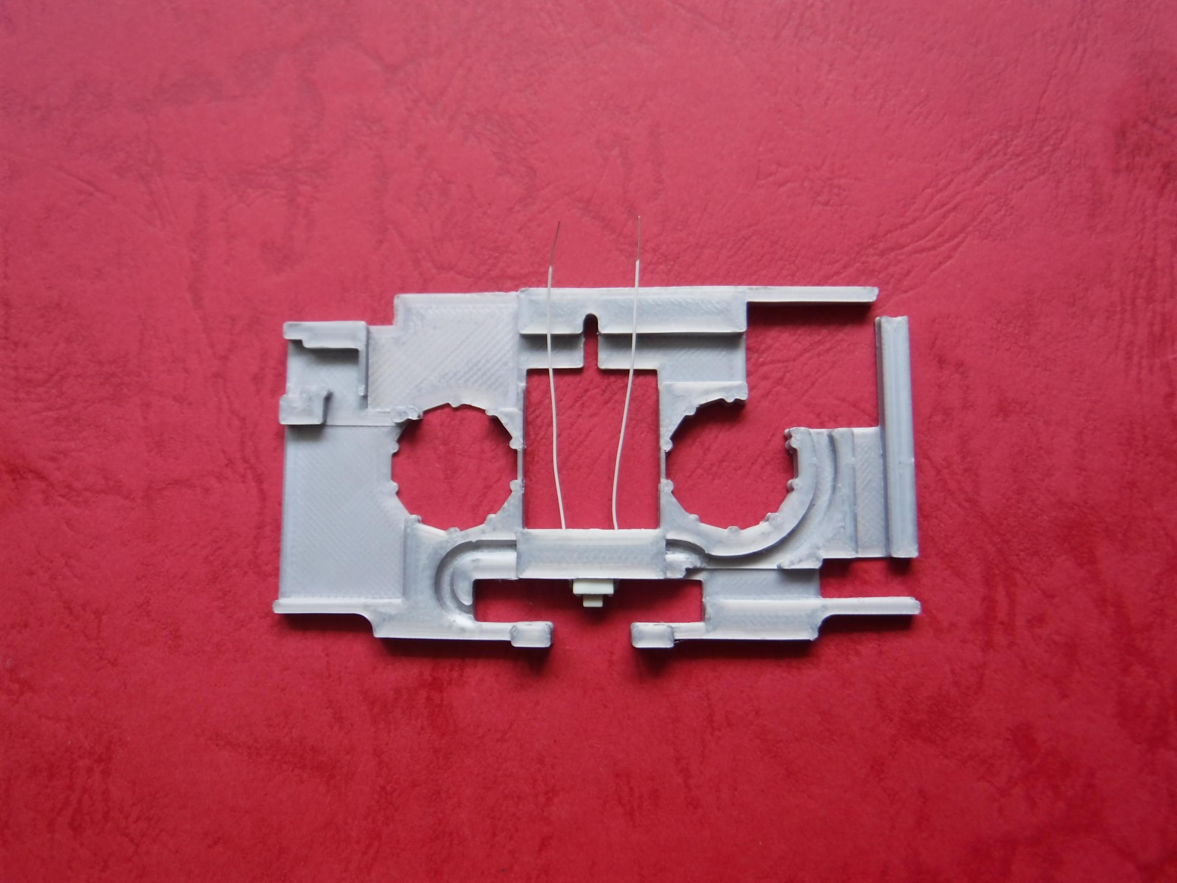
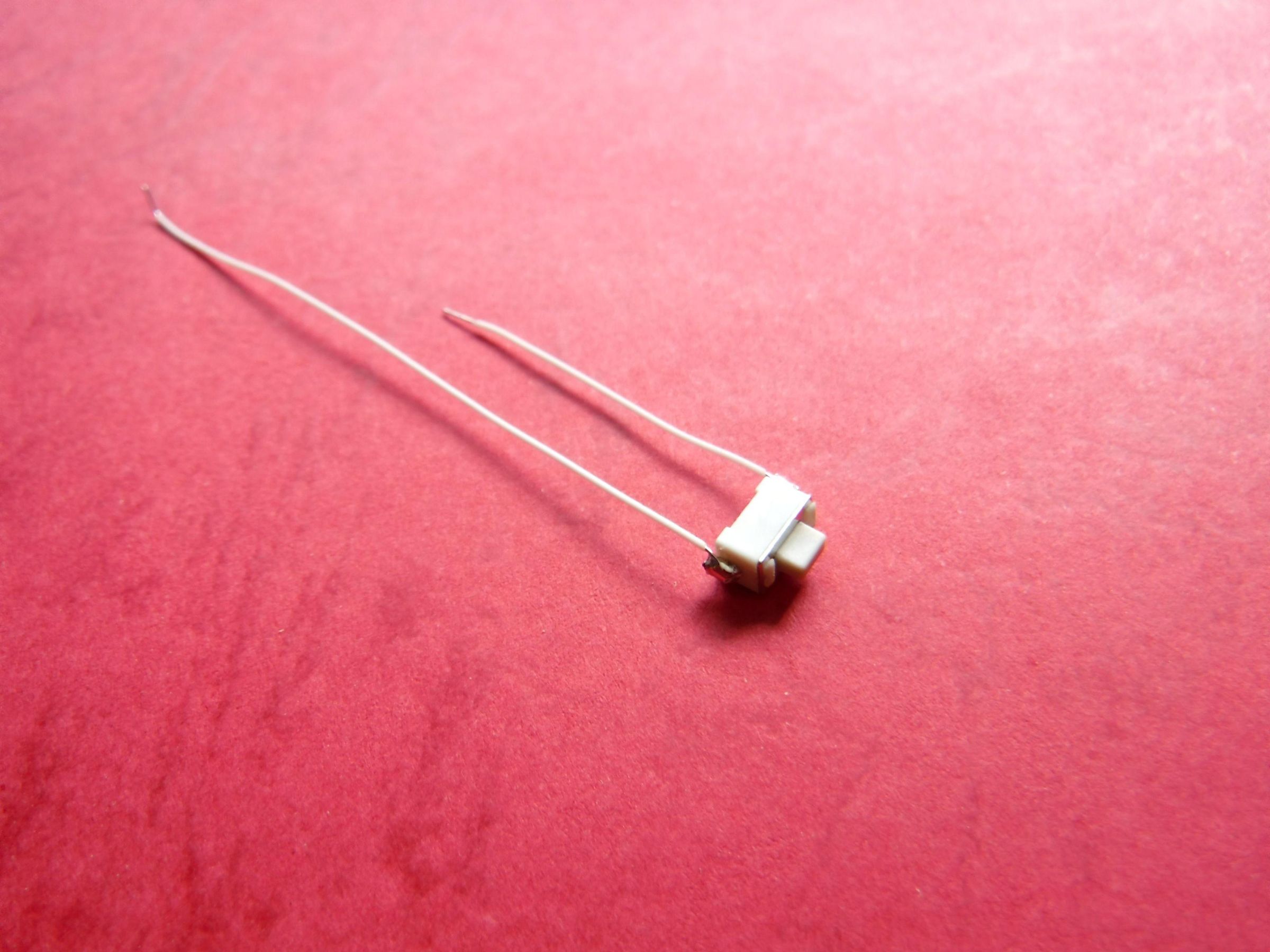
Fitting the tape head in the cassette retainer.
Prior to fitting the tape head a switch needs to be fitted in the pocket behind the tape head.
Solder (keeping application to a minimum), two long wires [6cm (0V)and 3cm (GPIO 0], to the switch and test operation with a DMM if there are no issues pass the wires through the two holes either side of the switch pocket.
Test the fit of the switch in the pocket as excessive solder can impede the fit.
Remove any excess solder as necessary to allow the switch to fit.
Refitting the Tape Head
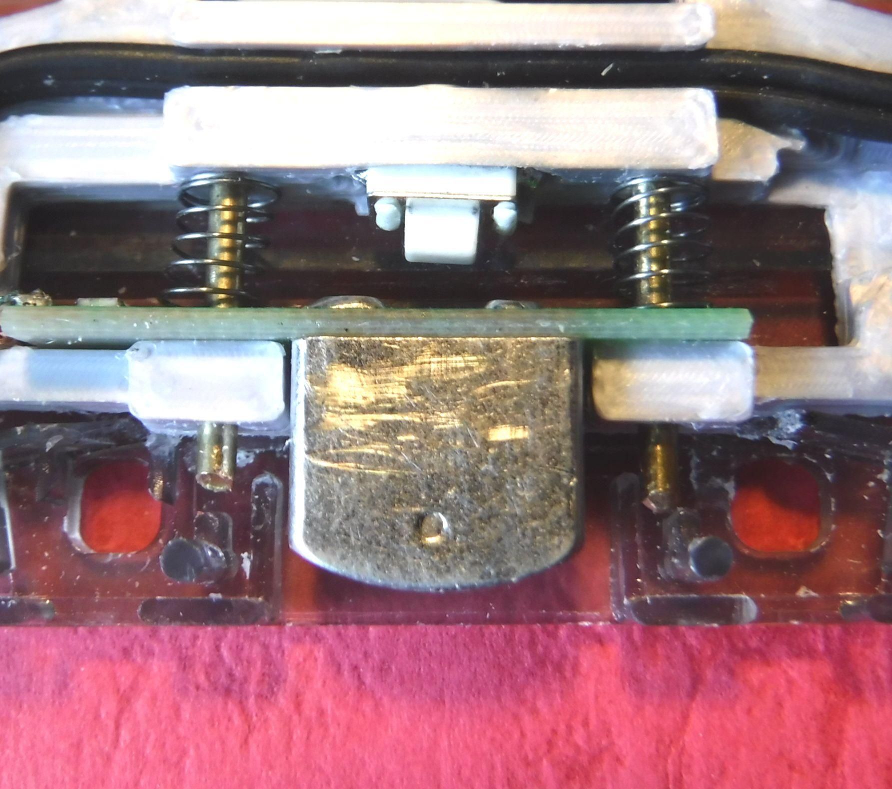
The removed tape head is fitted to the retainer with two 14(L) x 1.5(dia.) mm brass rods and the springs.
The rods are cut from longer stock either using a hacksaw or a stout wire cutters.
Be sure to round off at least one end on each rod to enable easier insertion.
The rods are passed through the front of the two holes in the retainer, through the holes of the tape head PCB and through the springs and into the coincident holes.
The tape head requires a horizontal front to back travel of 4mm with the switch activated at the end of the tape heads travel.
The short wire stub from the tape head is passed through the channel that runs behind and parallel to the tape head.
The end of the stub is attached to the earphone socket.
An additional length of the wire used to make the stub is extended from the earphone socket to the DFPlayer to pins 4 (DACR), 5 (DACL) and 7 (OV).
Switch Shim
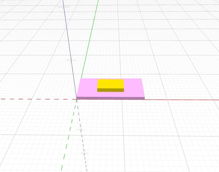
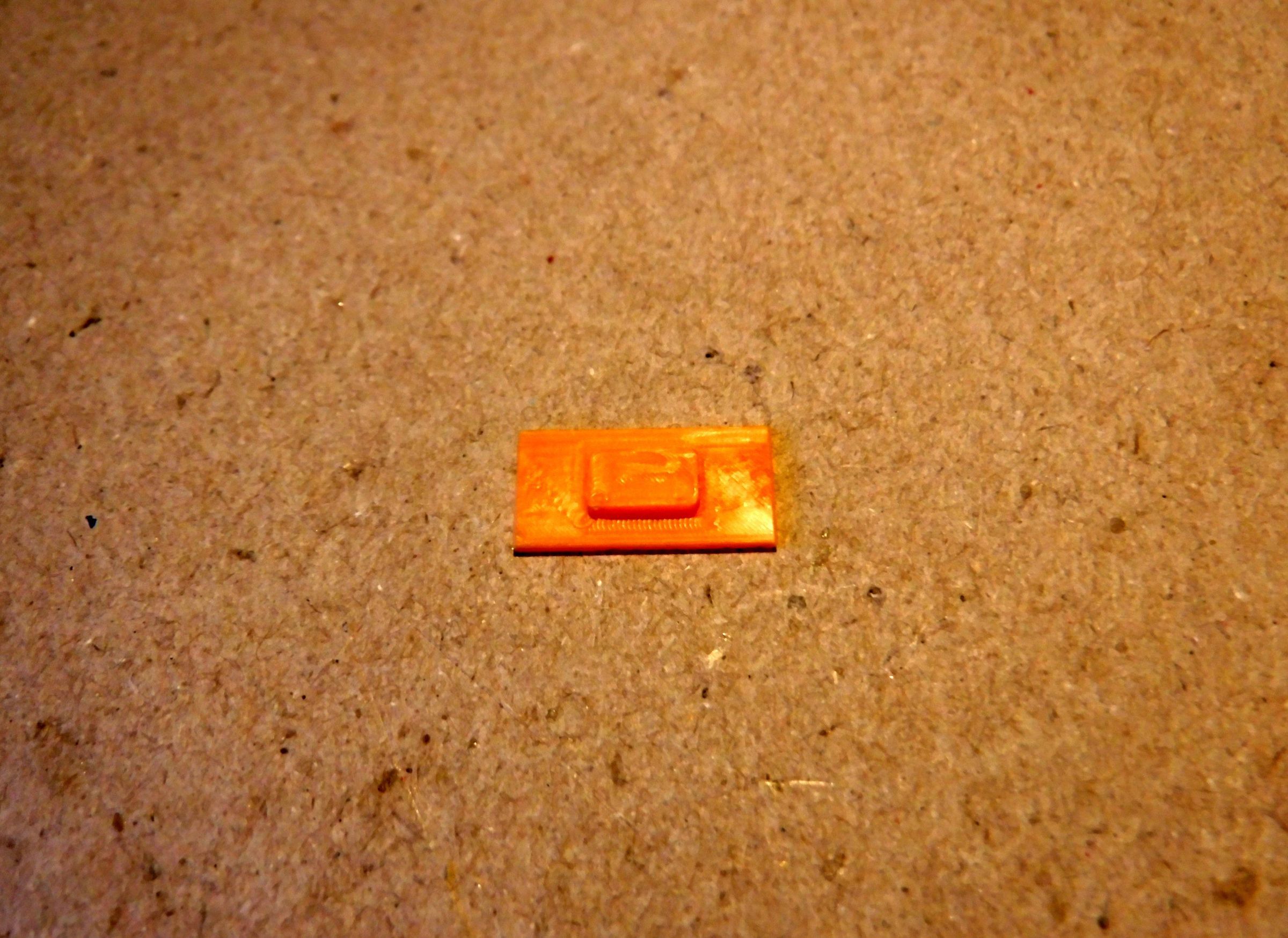
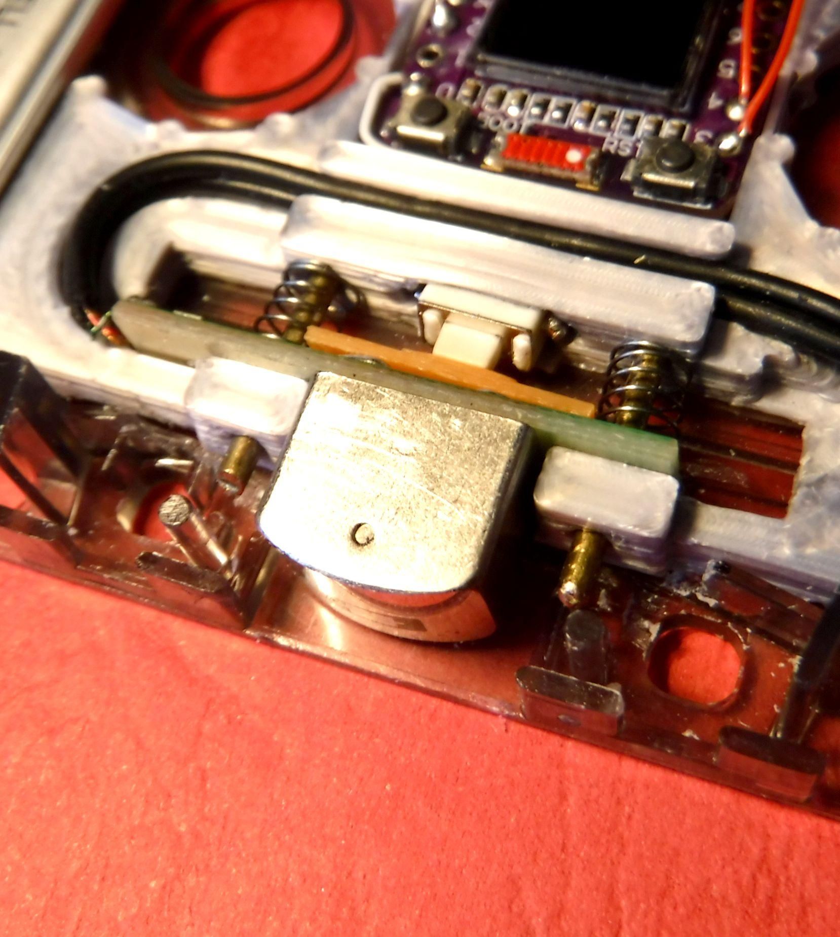
The switch shim sits between the tape head and the switch.
This controls the amount of travel required to activate the switch when the head of the cassette player contacts the head of the tape cassette.
It may be necessary to adjust the thickness to compensate for variations in travel between players.
The shim can be sanded thinner if necessary or the thickness increased by the addition of thin tape or by a suitable thickness of clear flat PET from a blister pack.
The switch shim has the raised centre due to the step in the cassette body which would prevent a uniform shim making contact with the switch button.
Dimensions: 15(l) x 7(w) x 1.75(h)
Downloads
DFPlayer Mini
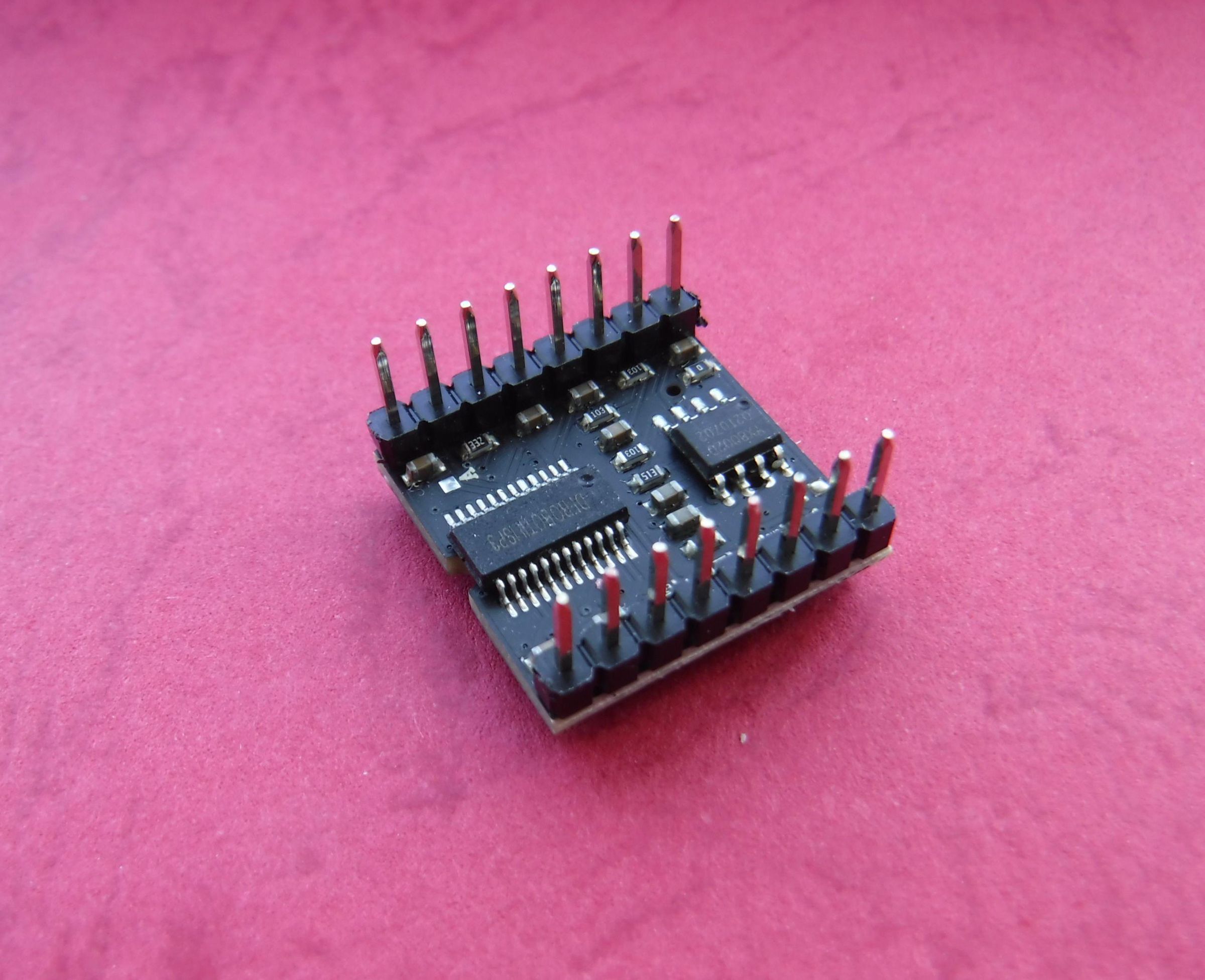
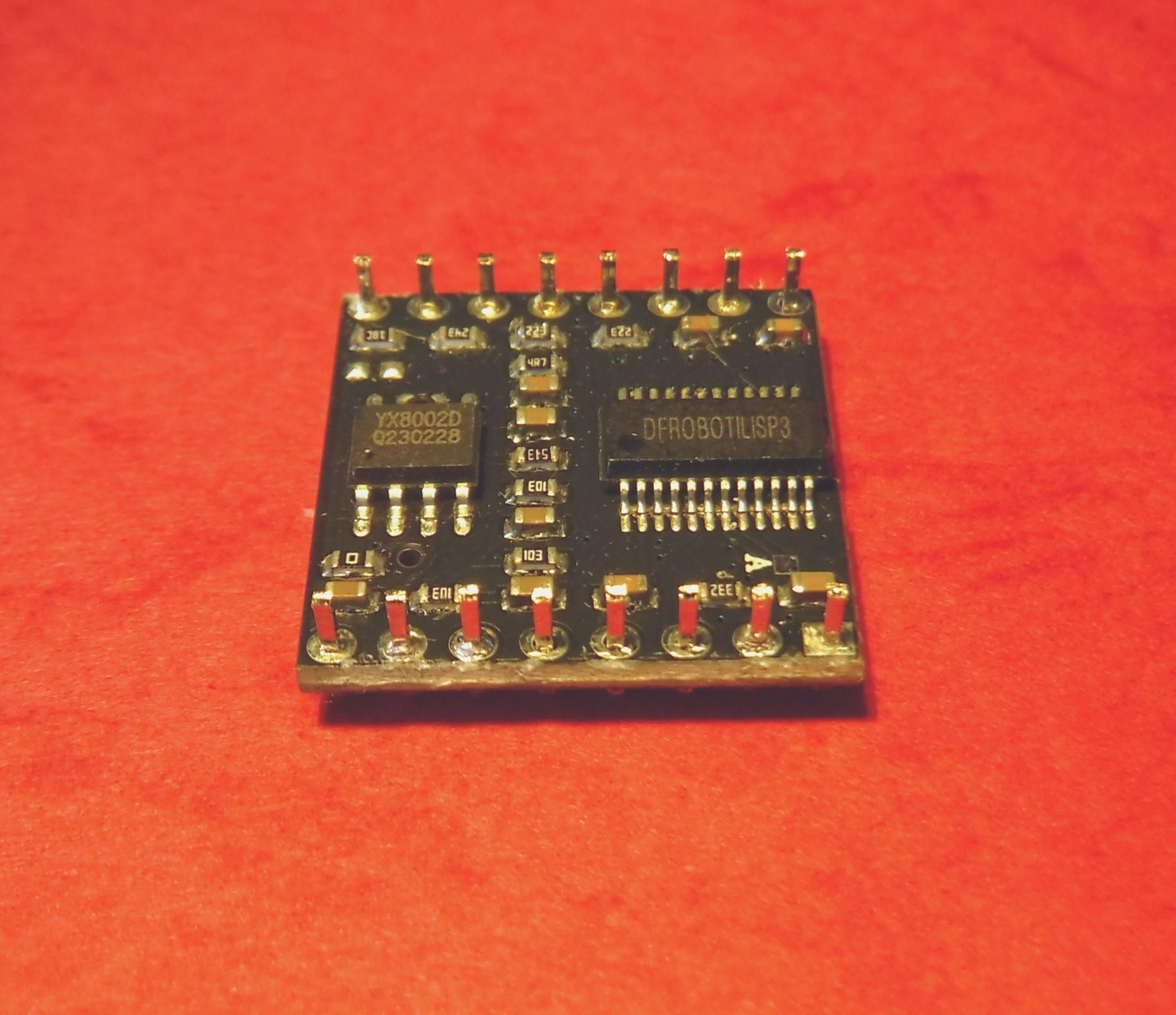
The DFPlayer Mini as supplied comes with headers.
However, these headers prevent the DFPlayer fitting into the cassette.
To enable it to fit within the cassette the header pins will need to be shortened by cropping the pins.
An alternative is de-soldering although the possibility of opens due to track breaks or shorts due to solder bridging or localised heat related issue were considered but cropping and sanding were considered less damaging.
Preparing the DFPlayer.
Due to the likelihood of static generation during this process that may damage the device observe anti static precautions
With cutters crop the pins close to the body of the header.
Next carefully remove the body of the header by pulling with pliers.
Tightly wrap the device with aluminium foil, ideally placing the sanding paper on an ESD mat and wearing an ESD wrist strap. In any event sanding in a slow circular should be favoured instead of rapid circular motions to reduce static build up and allowing dissipation between cycles.
Lightly sand the header pin stubs on a sheet of sanding paper level with the IC's taking care not to sand the text off the IC's.
Carefully remove the foil and remove any dust with an air blower and/or static free brush.
No issues were found using this method.
Micropython Install
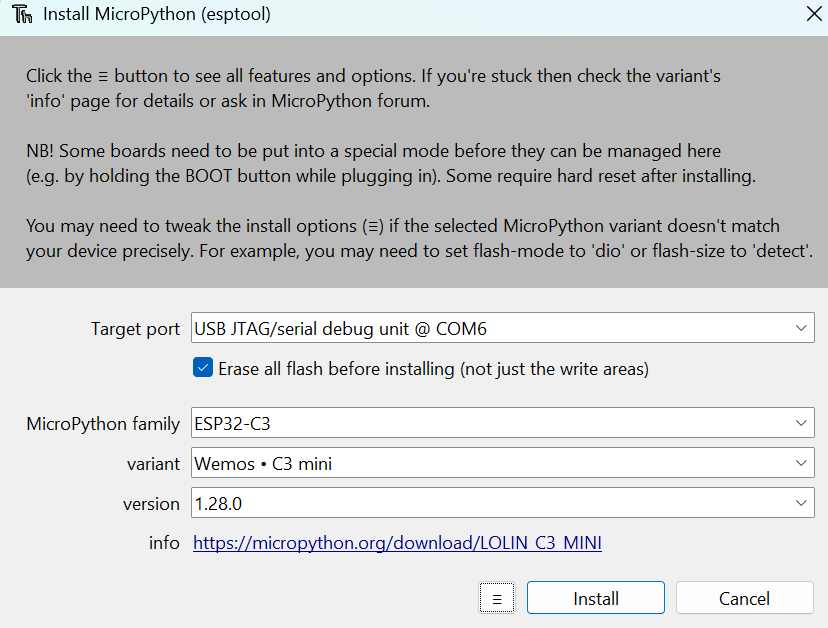
Micropython will need to be installed on the ESP32_C3 prior to use if this is not already the case.
Installing Micropython using Thonny.
Within Thonny select the following:
Tools > Options
On the options menu select the Interpreter tab.
Select the 'Micropython (ESP32)' from the dropdown.
Plug the ESP32_C3 into the USB port whilst holding the Boot button.
Select the port on the 'Port or WebREPL' dropdown.
Select 'Install or update Micropython (esptool)' then OK
On the resulting menu populate the empty fields as per the example image.
Noting that the Target port will reflect your USB port allocation.
Select Install
Once installation is complete close the window.
A successful install should show the version in the Thonny Shell.
If its not shown select Run > Stop/Restart backend to refresh the Shell.
In this case the version is:
MicroPython v1.28.0 on 2026-04-06; LOLIN_C3_MINI with ESP32-C3FH4
Application Software

Prior to wiring the elements together load the software on to the microcontroller as this will cause less disturbance to the wiring.
Create a folder on the ESP32_C3 named lib.
Into this folder copy the following libraries.
ss1306oled042b.py (OLED display driver)
dfplayer.py (DFPlayer mini driver)
Save the file dfplay_espc3_6.py to the ESP32_C3 as main.py in the root directory.
This will cause the application to autorun on powerup.
References to sources for the libraries (display and DFPlayer), used are listed in the software.
The GPIO and pin allocations are as follows.
GP21 [p05] TX UART0 DfPlayer (RX [p2])
GP20 [p04] RX UART0 DFPlayer (TX [p3])
GP05 [p11] SDA I2C0 OLED [internally connected]
GP06 [p12] SCL I2C0 OLED [internally connected]
GP10 [p16] Button1 play/stop
GP09 [p15] Button2 rewind (REW)
GP08 [p14] Button3 fast forward (FF)
GP04 [p10] Button5 Vol +
GP03 [p09] Button6 Vol -
GP02 [p06] Battery Monitor
GPO0 [p08] Tape head Switch
I was able to upload the library files as text/py files however for some reason I was unable to upload the application file as is which is also a text/py file. Therefore this had to be converted to PDF before uploading.
Wiring
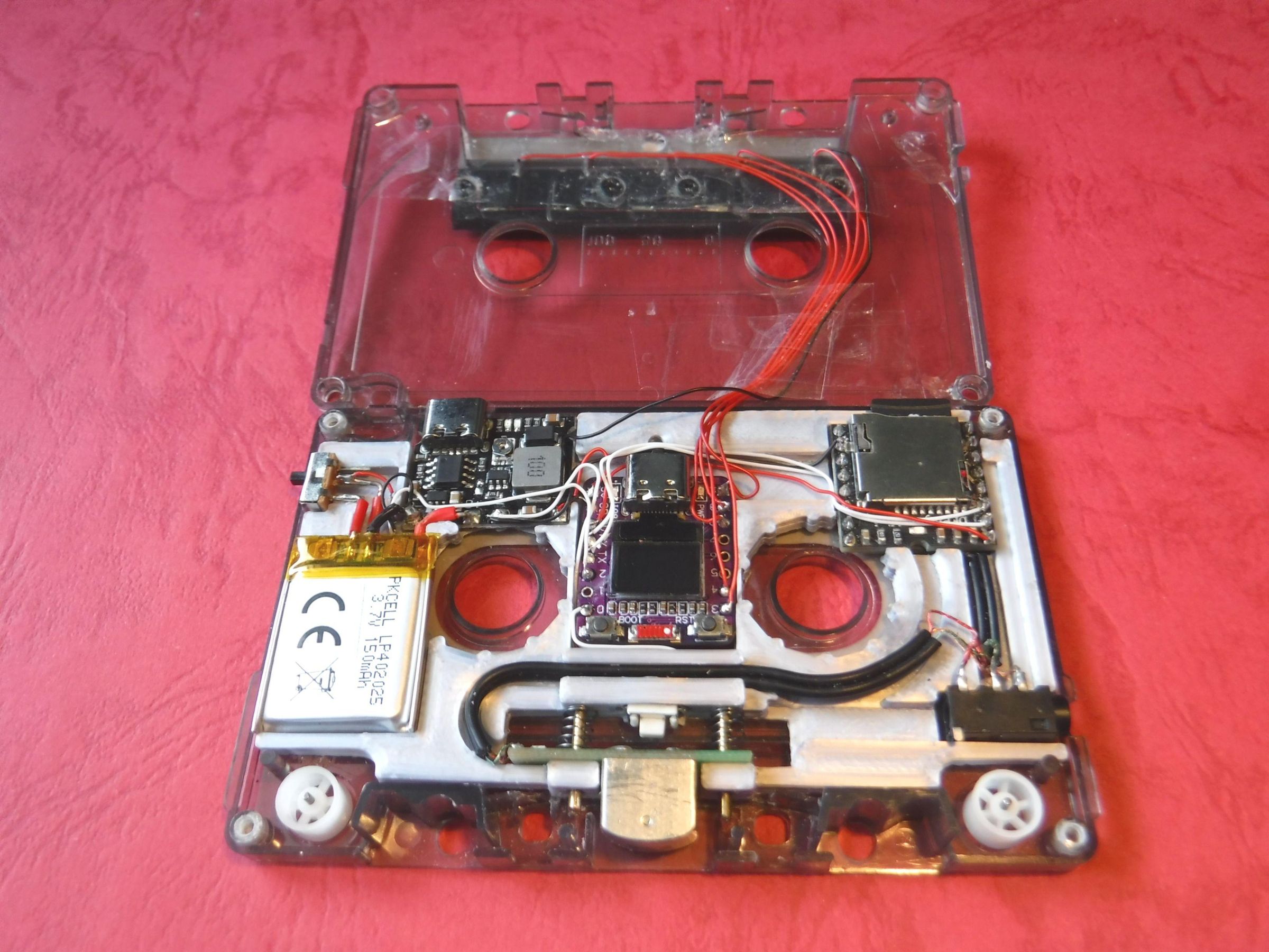
Channels have been created in the retainer in which to run some of the wires, helping to keep the wiring neater and flatter reducing wire stacking and bunching which creates high areas that will compromise the ability to close the cassette body.
Colour coding the wires can aid in wiring consistency and fault finding.
The wires on the battery as supplied are too long and need to be shortened to around 10mm in length.
Sit the slide switch and the battery in their respective pockets and solder the +Ve lead to the closest terminal on the switch.
Fit the charger/booster in its pocket and solder the battery -Ve terminal to the B- pad on the charger/booster.
With the switch in the off position solder a wire from the centre terminal of the switch to the B+ pad on the charger/booster.
Plug in the USB lead in the charger/booster and charge the battery, unless it has been previously charged.
Monitor the voltage at the output pads of the charger/booster with a DMM and adjust the potentiometer to set the output to 5V.
Remove the USB lead and put this to one side while the rest of the circuit is being built.
Wire the the tape head switch to the ESP23_C3 at GPIO0 and 0V.
Connect two lengths of wire one from the DFPlayer 0V to the ESP32_C3 0V and from the ESP32_C3 0V to the -Ve pad on the charger/booster.
Wire the tape head to the earphone socket.
Then take a short length of the shielded cable cut from the jack plug and connect this from the earphone socket to DAC outputs and the 0V of the DFPlayer
Connect a length of wire from the DFPlayer V+ to 3v3 of the ESP32_C3.
Connect two lengths of wire from Rx & TX of the ESP32_C3 to the DFPlayer TX & RX.
Connect the 100k and 43k resistors in series by soldering were they meet together in addition to a length of wire. Then solder two length of wire at each end
Solder the centre wire at the junction of the 100k & 43k to GPIO0, the wire connected to the 100k to Battery +Ve via the switch and the wire connected to the 43k to Battery -Ve.
Wire the control switches to the ESP32_C3 at the relevant pads keeping the wires as short as reasonably possible as this will enable the top half of the cassette shell to be removed allowing easy access to the required elements.
The wires from the front switches should be short, parallel and held as flat as possible whilst allowing the two halves of the cassette to open out flat this ensures minimum bunching when closing the two halves.
In the absence of colour coded wiring a simple stripe marking system can be applied to the wires with a permanent ink pen. 1= 1 stripe, 2 = 2 stripes etc.
Finally connect the charger/booster +Ve pad to the 5v pad of the ESP32_C3
Check that the cassette closes evenly around the edges.
Ensure were possible that the wiring follows the cut outs.
Try to route wires by the side of the modules rather than over the top due to the low height of the space between the two halves of the cassette. This can create high spots that can prevent closure or stress the plastic at the point of contact or create a short circuit if a sharp point or edge pierces the insulation of a wire.
During the wiring process it may be required to close the two halves of the cassette to check the wiring position and high spots.
Temporarily secure the two halves of the cassette together with lengths of masking tape on the two sides and along the top. As this will prevent screw holes being worn by over use.
Remedy any high spots found.
Setup
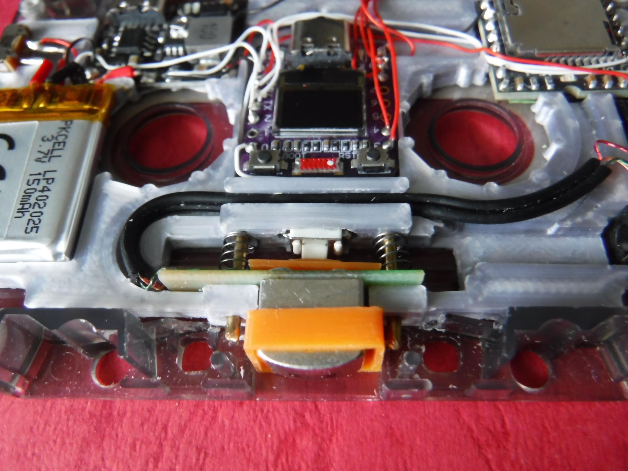
Due to variations in the mechanical mechanisms in different cassette players, some adjustment to compensate for these differences may be required.
The cassette head may have insufficient travel due to the switch being too far forward, preventing the players mechanism locking in place.
Alternatively, the switch may be too far back and not engaged by the cassette head.
1: Switch.
This can be moved forward by adding a 6(l) x 3.5(w) mm spacer of suitable thickness behind the switch.
Additionally the switch shim included can be thinned by sanding.
Sanding down the solder on the back of the cassette head PCB ensures the switch shim connects squarely with the switch button.
Check that the switch engages when the cassette tape head is pressed.
2: Centring Frame.
Designed to align the heads of the player and the cassette.
However, the player head can have different configurations which may affect how this interfaces with the cassette head, such as two to four tape guides which could be straight or bent.
This may require some filing of the centring frame to prevent fouling.
Temporarily secure the two halves of the cassette together with lengths of masking tape on the two sides and along the top.
Fit the frame around the cassette tape head.
You should be able to press the cassette tape head to engage the switch and the head should return to its rest position. If it sticks file the inner surface of the frame to widen the opening
Remove the temporary tape and secure with the screws.
Music Files
The DFPlayer supports MP3, WAV and WMA formats on a MicroSD card up to 32Gb.
Prior to use format the MicroSD card to FAT32.
Using this library you can create up to 99 folders with 255 files per folder.
Each folder is numbered sequentially without gaps using the format NN, E.g. 01, 10
Each file is numbered sequentially without gaps using the format NNN, E.g. 001.mp3, 010.mp3, 100.mp3.
Unfortunately this entails renaming a clear filename to a numeric filename losing any descriptive meaning.
Operation
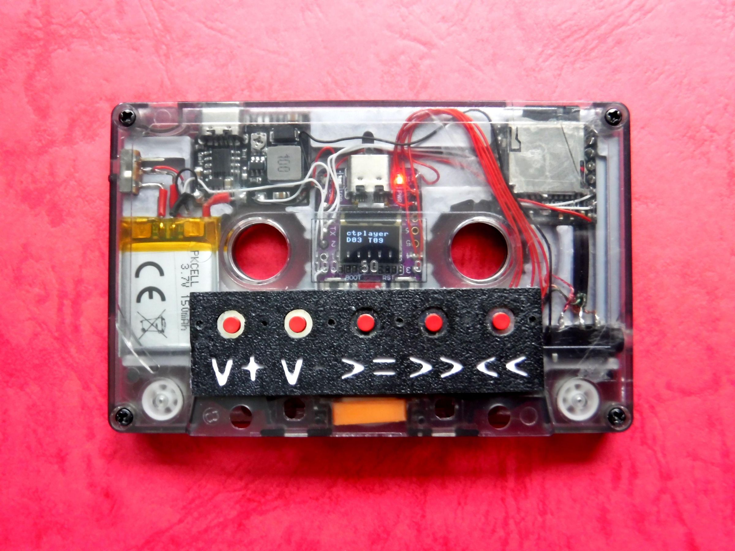
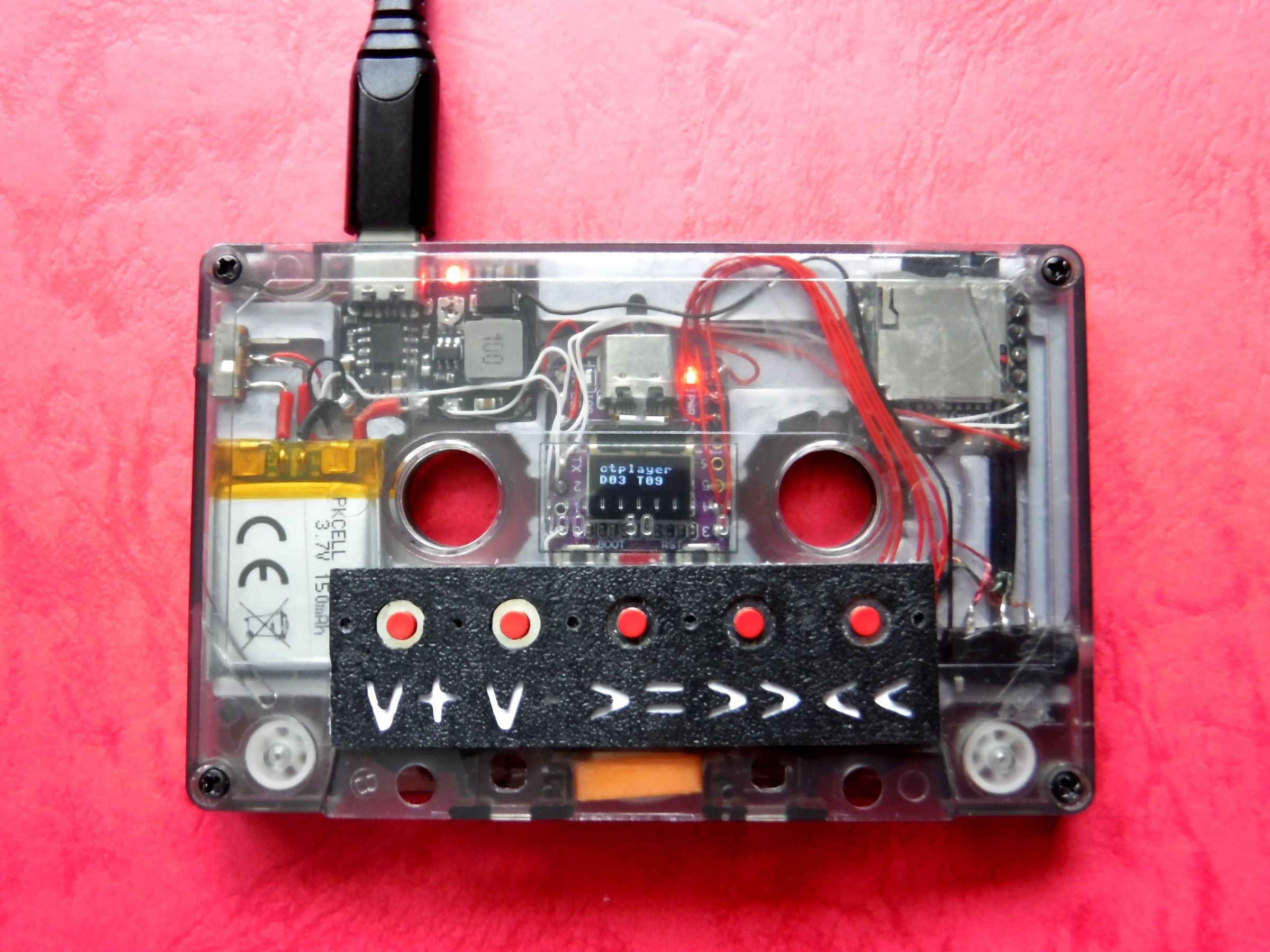
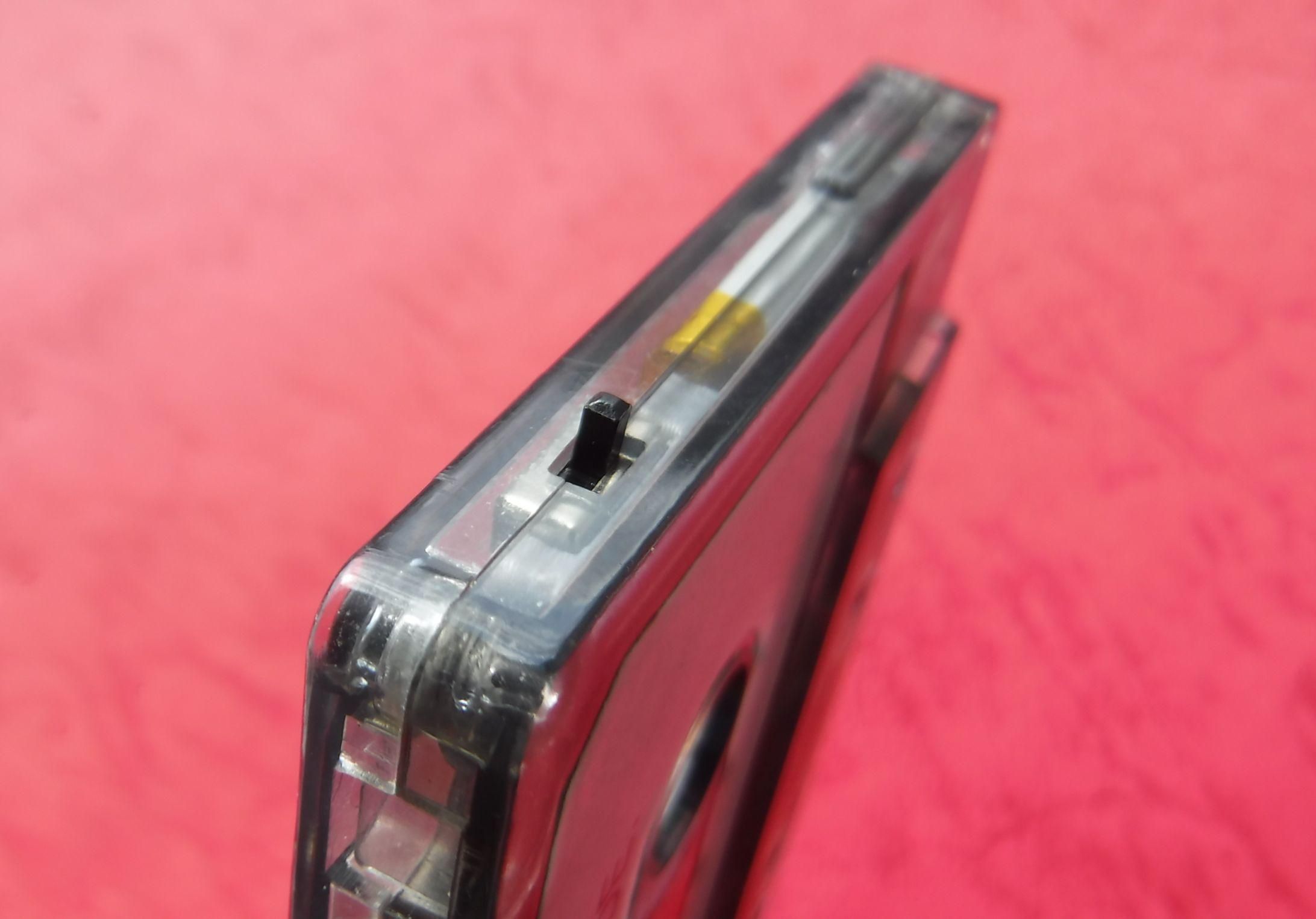
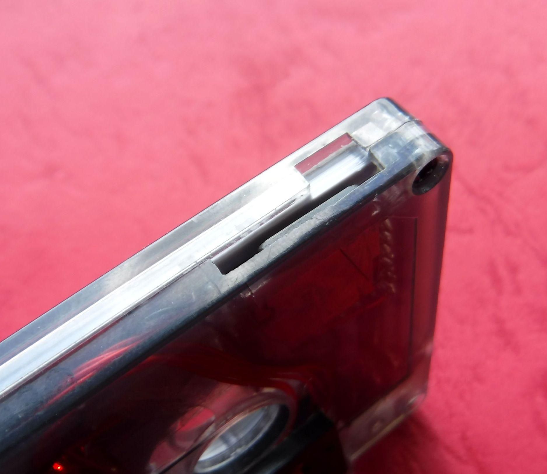
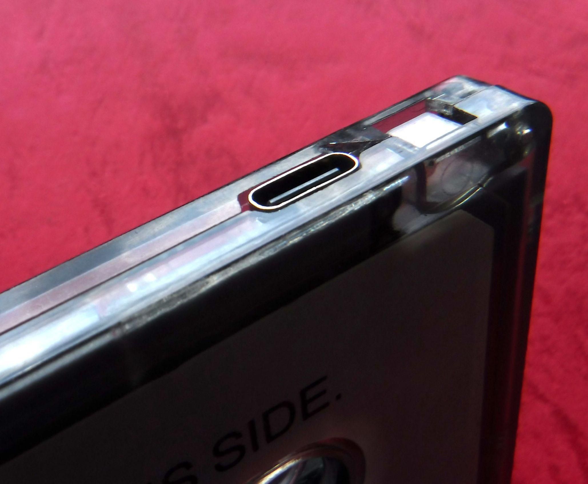
The unit can be powered by USB only with the power switch disengaged or via the battery with the power switch engaged.
Charging is accomplished with the unit powered by USB and the power switch engaged.
Charging current consumption is dictated by the state of battery charge reducing as the battery nears full charge.
Operational current consumption is ~50mA.
There are two modes of operation stand alone and paired.
In either mode the unit requires a correctly formatted Micro SD card with the required folder structure and naming convention.
Switch on the player using the slide switch situated on the upper left hand side.
If there are music tracks on the player the display will show the number of directories and files and stop in the following form.
DNN FNN
STOP []
If there are no tracks or no SDcard the following will be displayed:
No_Trk
STOP {}
Stand alone mode
In this mode of operation the player is controlled by the front panel buttons.
Insert the 3.5 mm plug of the headphones into the socket.
Adjust the start track using the FF or REW buttons if required and press play
Adjust the volume as necessary this will be shown on the display as VOL NN (where NN is the value)
The player will progress through the tracks until it reaches the end of the files and stop.
Pressing play/stop at any time will stop the player at the current track.
Press play/stop to continue playing.
The battery charge will be shown on the display in the following form Bat NN% (where NN is the value)
Paired mode
Not to be confused with BLE pairing, this requires two devices the tape cassette player and the MP3 cassette.
Insert the cassette into the tape cassette player and press the play button on the tape cassette player.
The player will progress through the tracks until it reaches the end of the files and repeats from the beginning.
Press stop on the tape cassette player to stop the player.
The control buttons are not accessible due to the door or flap on the tape cassette player.
In either mode do not forget to switch off the MP3 cassette to save battery power.
Display Blanking
The display will be blanked after a period of time (60 sec), to conserve the display due to pixel ageing if the buttons are not pressed. No significant reduction in current consumption occurs with the display blanked.
If a button is pressed the display will be reactivated and reset the blanking timer.
Further Activities
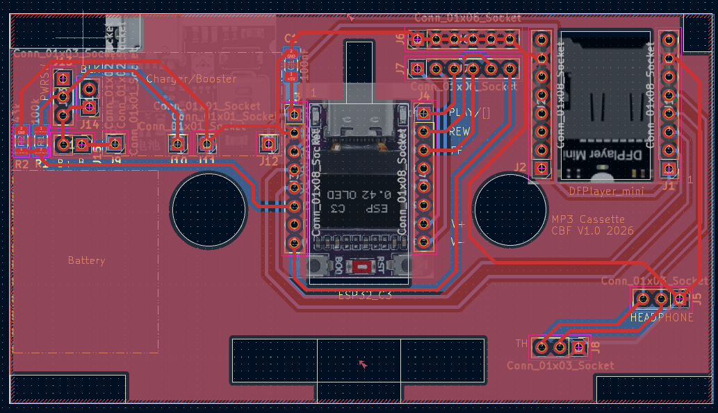
1: A PCB to reduce the wiring limitations and ensure consistency of build. (Design for the current version complete).
2: A custom cassette case to allow the DFPlayer to be moved into the corner to allow the inclusion of both spools. An opaque rather than a clear case due to the limitation of crystal clear prints, necessitating a centre cut out.
Both these changes will necessitate some modification to the retainer and cassette to provide support for the tape head and switch.
3: Incorporate the switch panel into the step of the custom cassette body.
Finally
As it stands the project is fully functional and sits within the areas of reuse and off the grid.
Reuse - A cassette that may otherwise be redundant given a new lease of life and if you have a player you have a reason to reuse it without the worry of tangled, stretched or worn tapes.
Off the grid - A rechargeable battery powered, portable music player that fits in a pocket.
Hope you made it this far then thanks for reading.