MS_RCWATCH
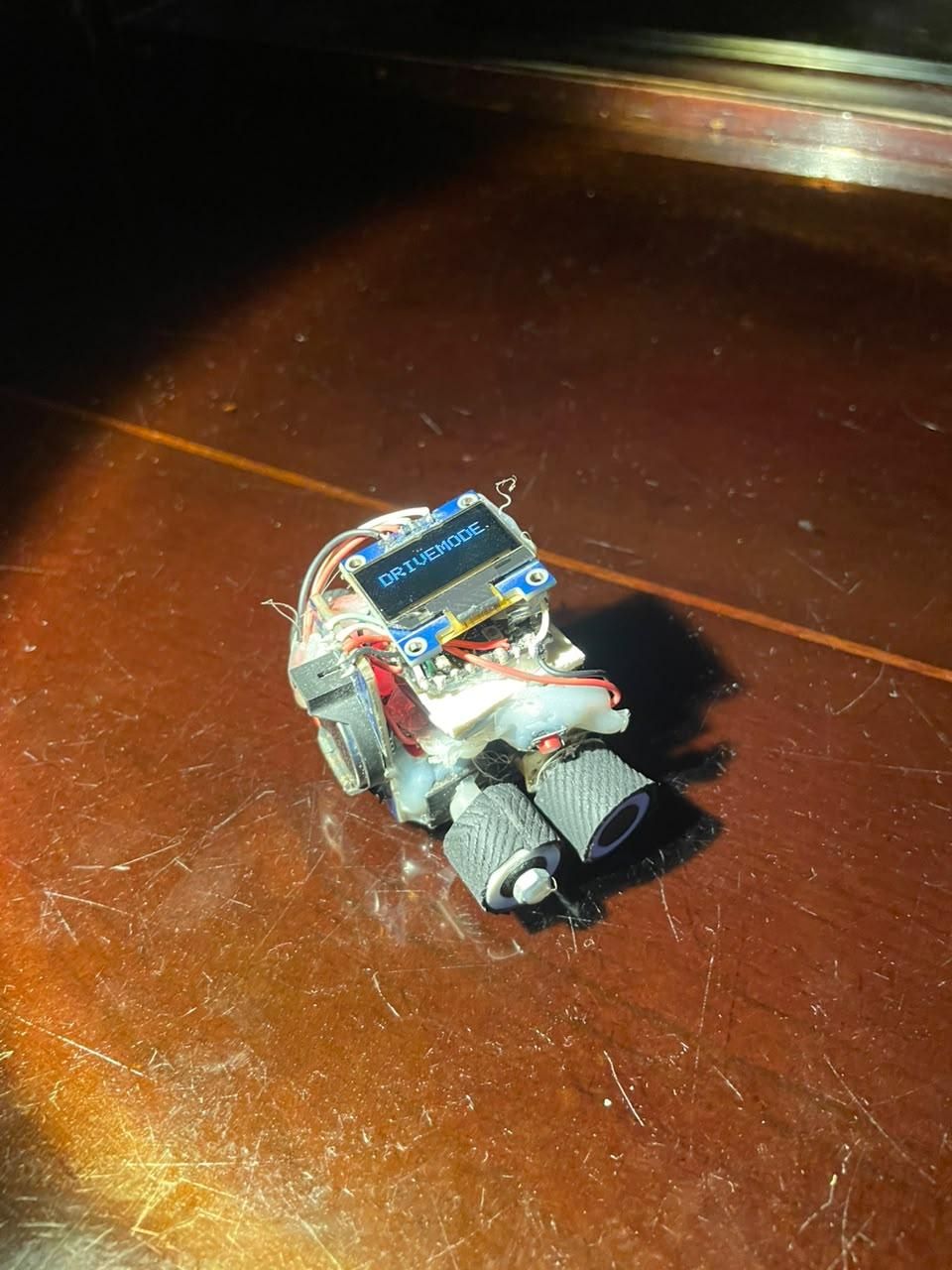
The place from where the idea came into my mind,
As being a teen member of such a family where there are very few peoples of my age. This makes me feel bored in family meetings. So, recently during a family reunion I was bored as usual I was just waiting for the moment to leave and I looked at my wrist watch to see the time and suddenly a idea hit my mind, What-If? As roboticist, I fit something humorously tiny and fun in it. This is how the idea of first-ever open-source smart tiny car fitted to a smart wrist watch 'MS_RCWATCH' came.
'MS_RCWATCH',
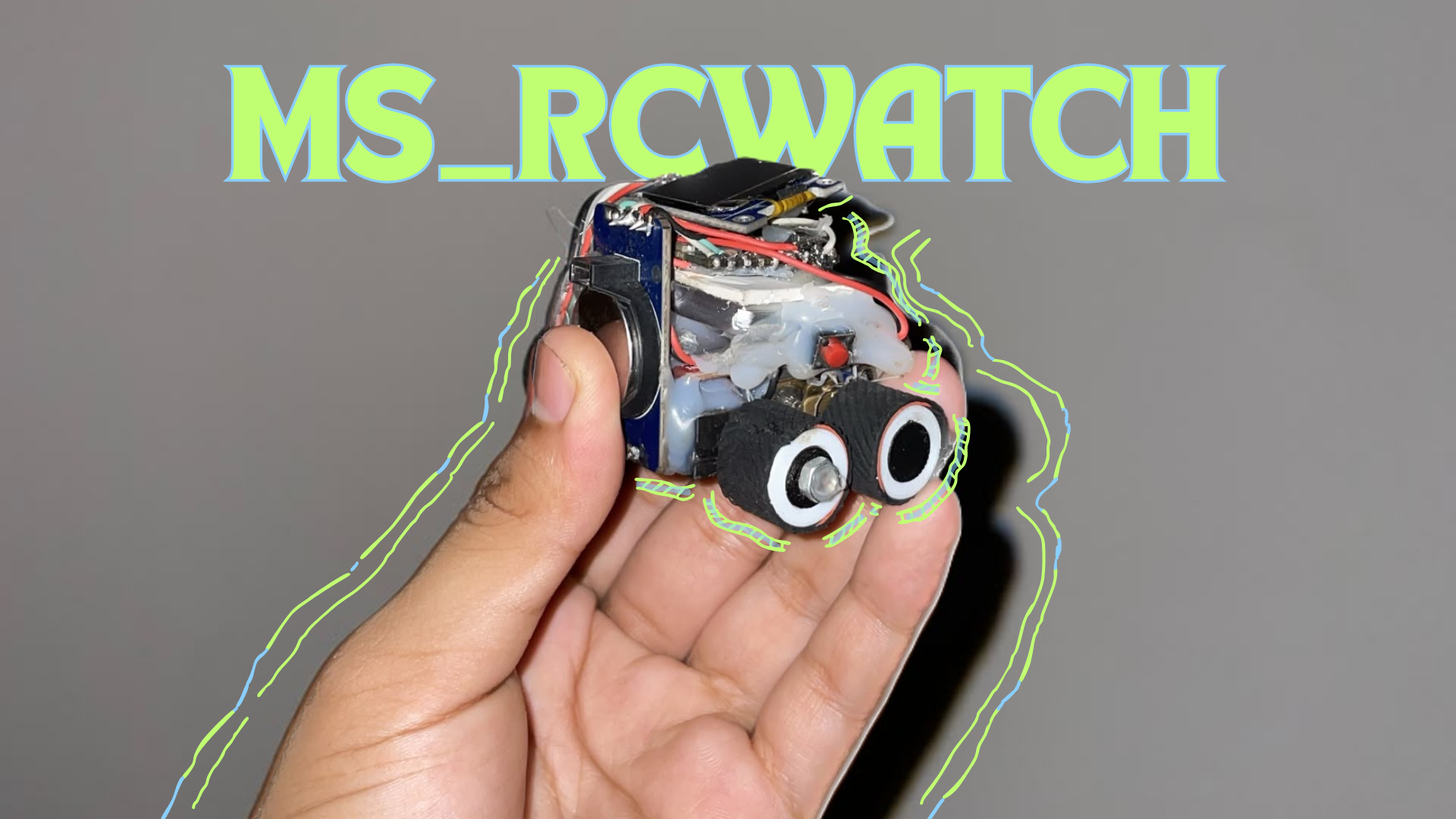
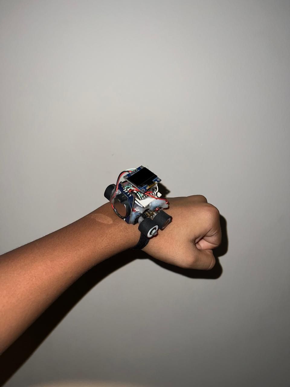
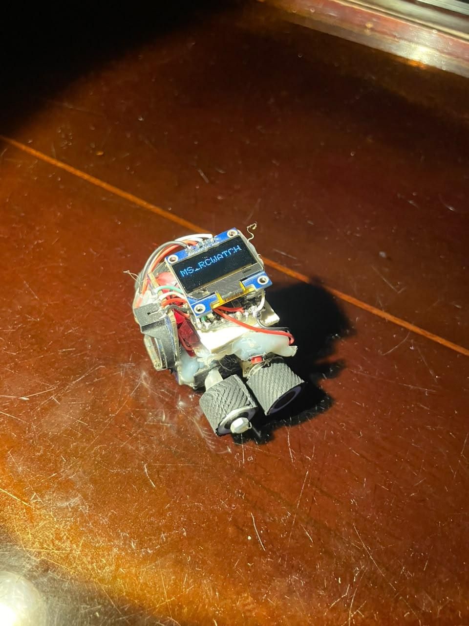
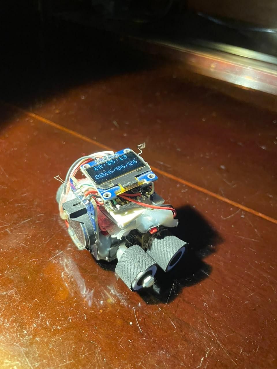
'MS_RCWATCH' is a tiny RC car fitted into a smart wrist watch. It can help you from getting bored, just think what could be more cooler than controlling a car with only your smartphone that just detached from your watch. And again just by a press of a button it turns into a watch. The watch has two modes 1. Watch 2. Drive-mode. Fully designed and programmed by me. *This is the first version of the 'MS_RCWATCH', I will start working on the v2.0 of the 'MS_RCWATCH' if I get good reviews from the first version, more developed and Product-Ready.*
Supplies
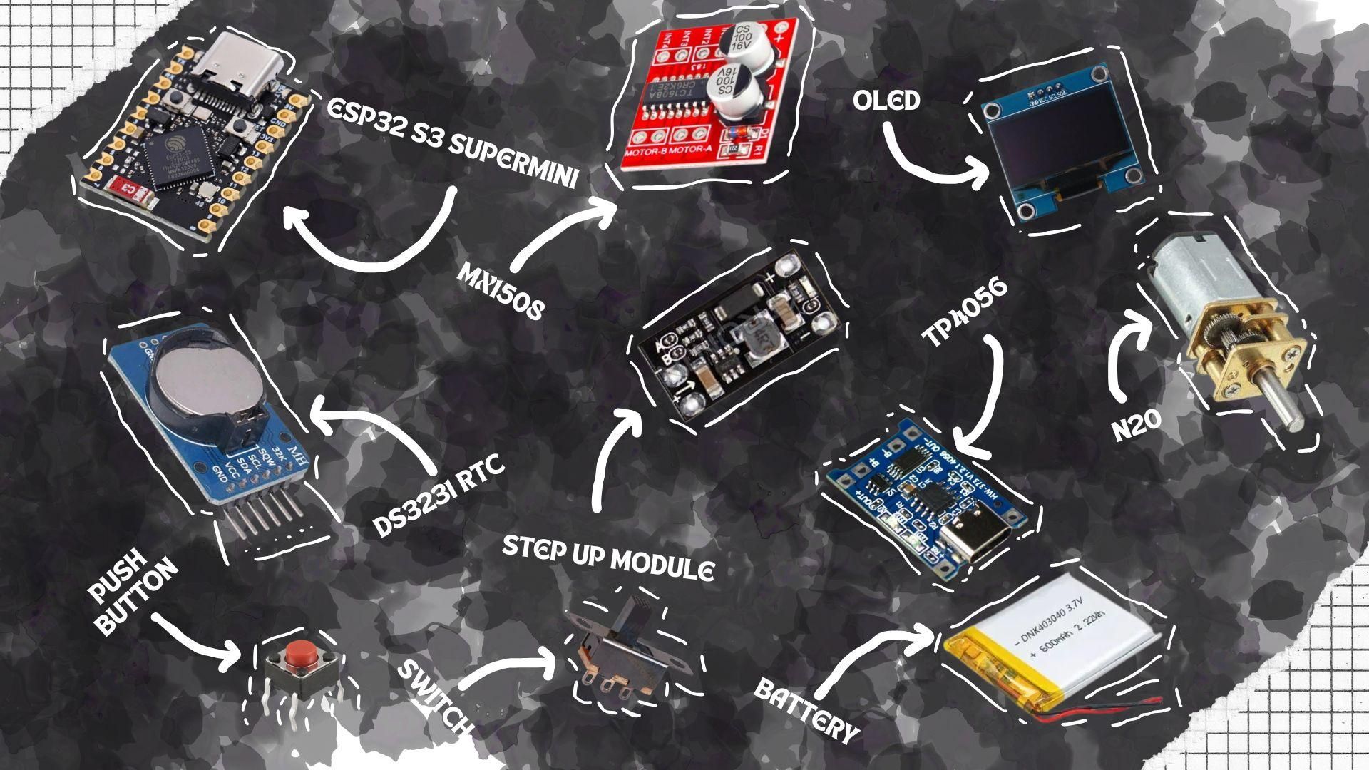
The list of components used in this project with quantity:
- ESP32S3 SUPERMINI DEV MODULE x1
- DS3231 RTC MODULE x1
- MX1508 MOTOR DRIVER x1
- N20 MOTOR x2
- 0.96" I2C OLED DISPLAY MODULE x1
- 3.7V 600mAh Li-Po BATTERY x1
- TP-4056 CHARGING MODULE x1
- 1.5A MULTI FUNCTION MINI BOOST MODULE x1
- TACTILE PUSH BUTTON 2 PINS x1
- MINI SWITCH x1
The list of tools used in this project:
- 3D-PRINTED BODY & PARTS
- WIRES
- 3MM MAGNETS
- SOLDERING IRON
- SOLDERING LEAD
- HOT GLUE GUN
- SCREW DRIVER
- 2x M3 10MM(SHORTENED TO 7MM) SCREWS
- 2x M3 NUTS
- 3MM x 1MM MAGNET
- SUPER GLUE
- CRICKET BAT GRIP
FIRST STEP
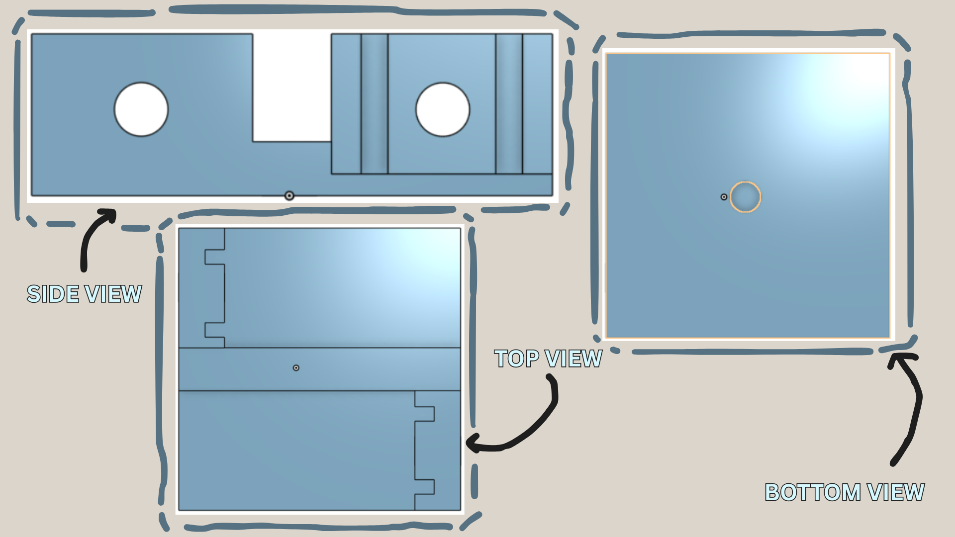
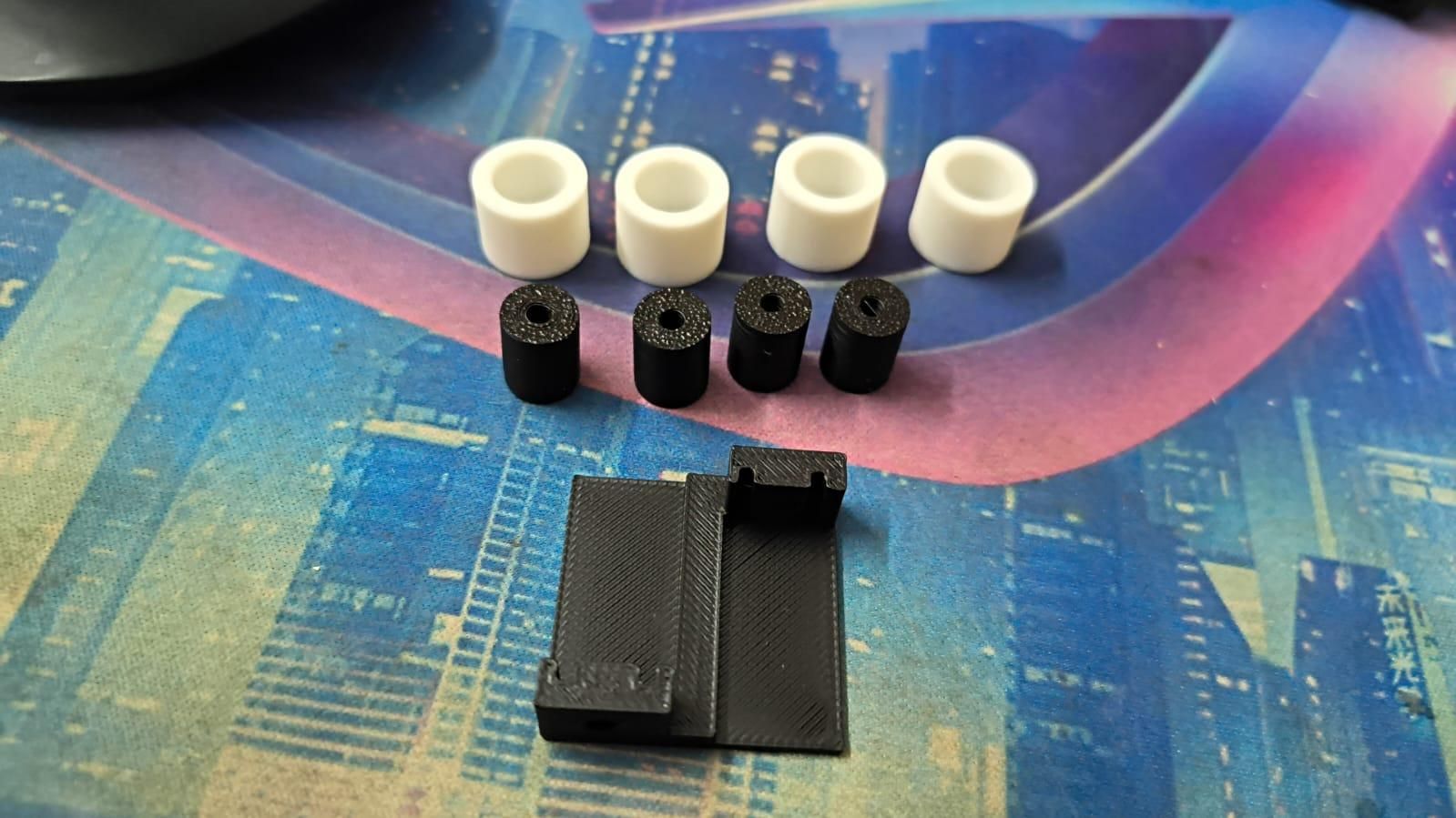
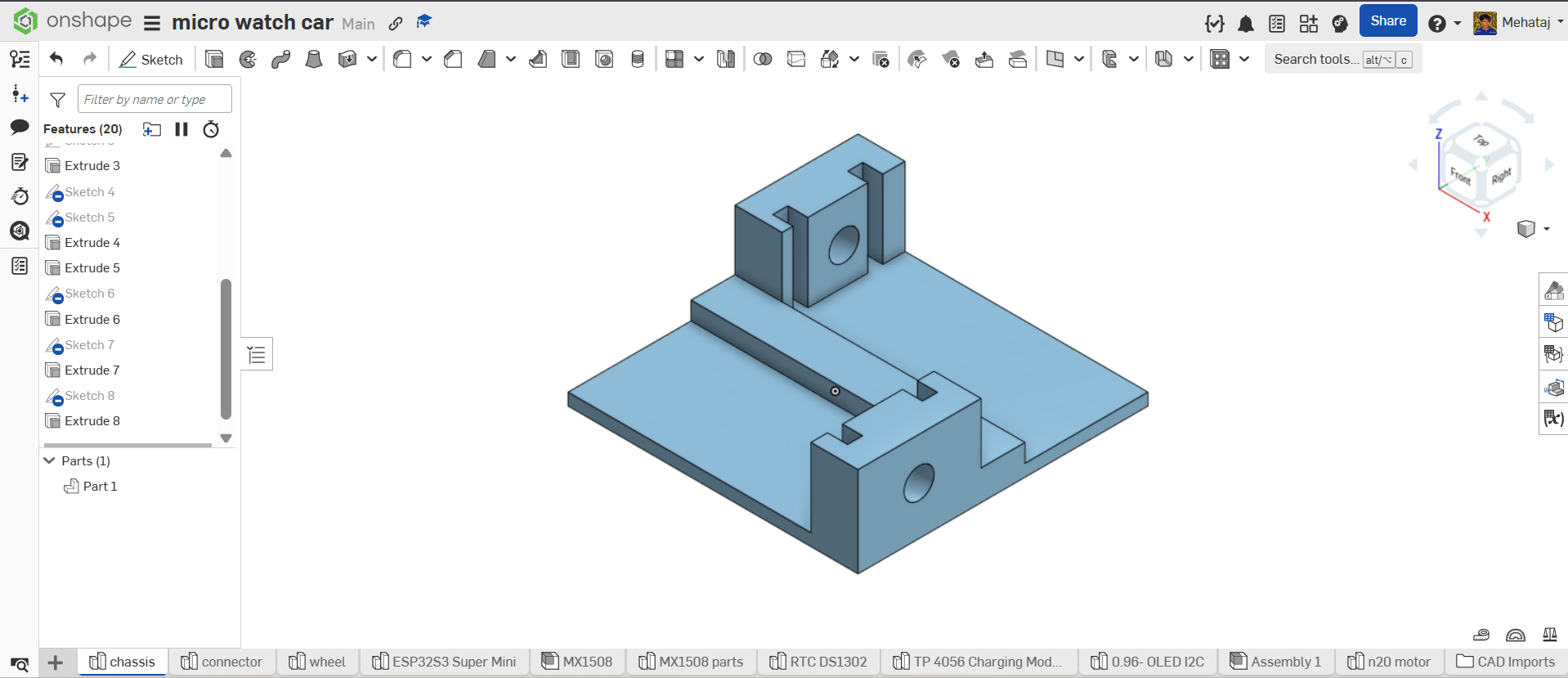
3D print the files, they were designed in 'onshape'.
In the Side view: The holes are for the two screws as there will be two free wheels. The linear cutouts are for the wires coming out of the motor.
In the Bottom side: The surface is a plain quadrilateral, just a hole in the middle where the 3mmx1mm magnet will be placed for a smooth wrist band detaching experience.
In the Top view: The open edges are for the motor, a divider in between too separate the motors.
ASSEMBLY-S-1
.jpeg)
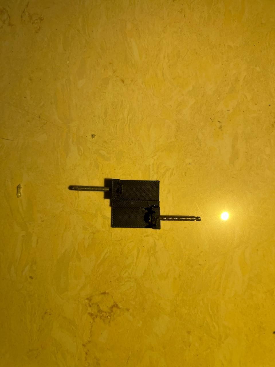
Insert the two screws in the holes for the screw. Do not forget to put glue on the head of the screw or it may damage your motor by shorting two ends.
ASSEMBLY-S-2
.jpeg)
.jpeg)
Now, attach the motor to the chassis on it's place. Make sure that the motor wires are fitted to the wire cutout. Do not let the glue go inside the motor gearbox, resulting damage to the motor and do not put too much glue on the motor it may affect your component placing.
ASSEMBLY-S-3
.jpeg)
Moving on, place the MX1508 Motor driver module on the top of the motors. Solder the wires from the motor to the motor driver, before placing other components.
ASSEMBLY-S-4
.jpeg)
Now, place the DS3231 RTC module to the back side of the bot (the part facing you as per you OLED placement).
ASSEMBLY-S-5
.jpeg)
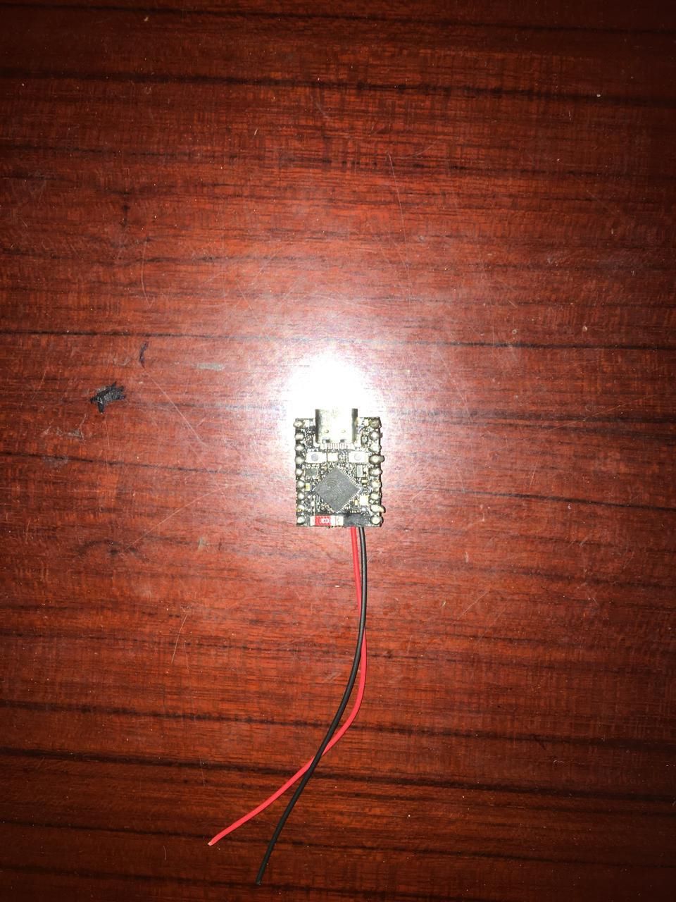
Now, it is a crucial step solder two wires to the ESP32S3 SUPERMINI 'B+' and 'B-' pins and then put some glue over it.
ASSEMBLY-S-6
.jpeg)
Now, place the li-po battery on top of the motor driver. I recommend to use a plain piece of plastic sheet between the motor driver and the battery.
ASSEMBLY-S-7
.jpeg)
Now, after connecting the battery and two wires to the Dev boards B+ and B-, place the Dev board top of the battery and connect all the wiring from the motor driver and DS3231 (OLED is connected to the DS3231).
ASSEMBLY-S-8
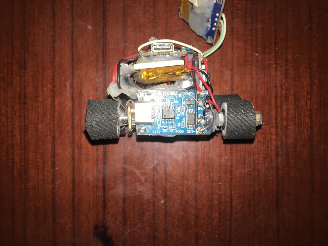
Now, connect the TP4056 charging module on the side opposite to the side where the RTC DS3231 is connected and connect the battery to it.
ASSEMBLY-S-9
.jpeg)
Attach the button on the side that just at the right of the RTC DS3231 over the motor and connect the wire to the ESP32.
ASSEMBLY-S-10
.jpeg)
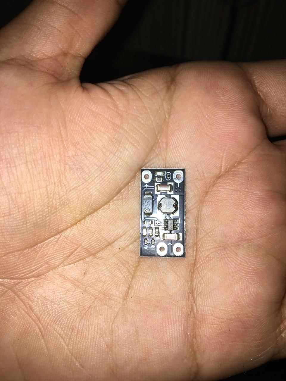
Now, attach the Step-Up module and connect the out of the module to the motors 'BATTERY IN' and connect the modules IN to the battery and connect the ESP32 Battery wire. *BUT CONNECT THE POSITIVE OF THE BATTERY TO THE SWITCH THEN CONNECT IT TO THE IN OF THE MODULE*
ASSEMBLY-S-11
.jpeg)
Add the switch on the opposite side where the button is connected, the positive of the battery should be connected to the switch.
ASSEMBLY-S-12
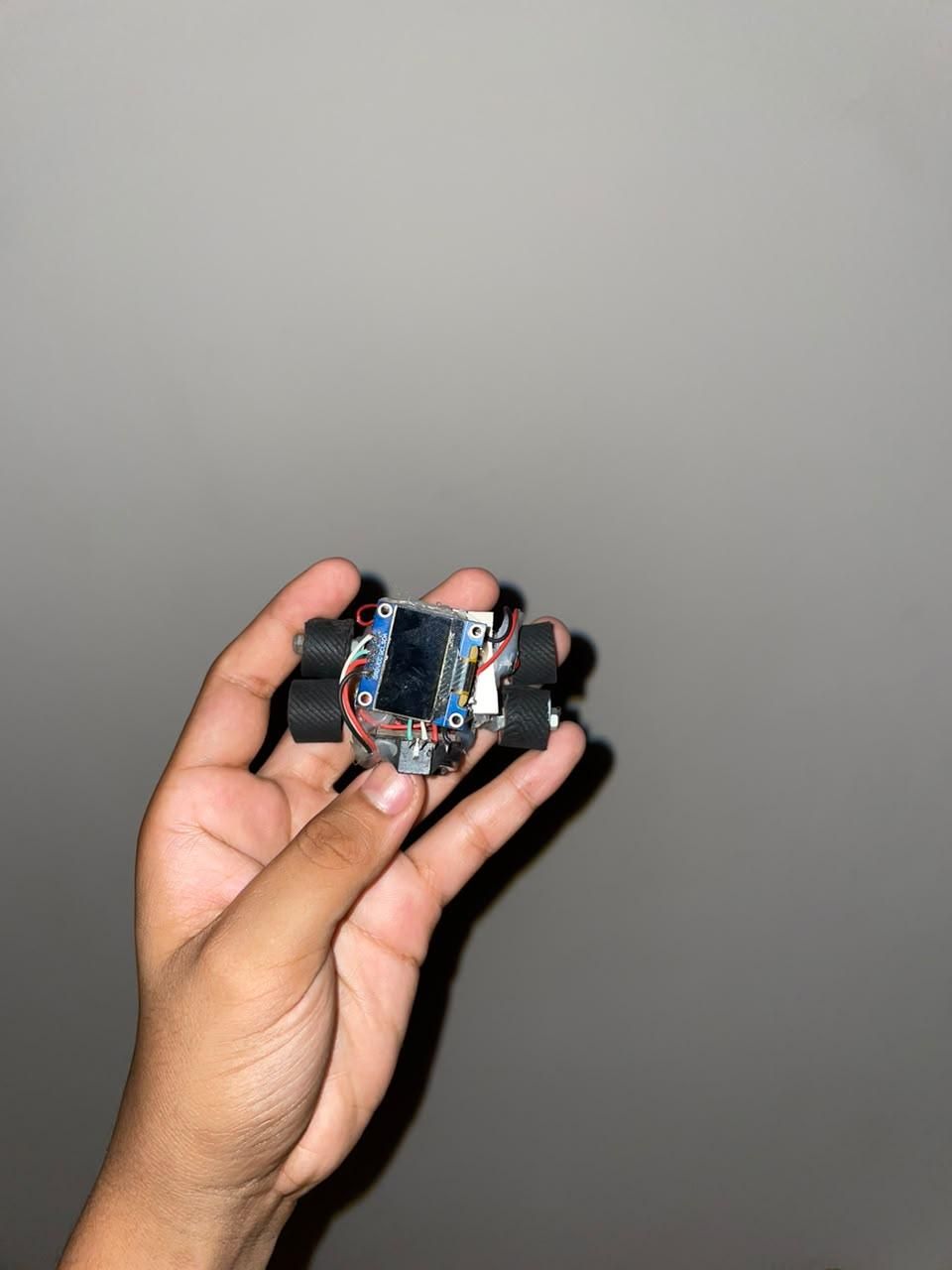
.jpeg)
Finally connect the OLED on the very top of the bot and connect the pins to the DS3231's I2C output pins.
BOT FINISHED
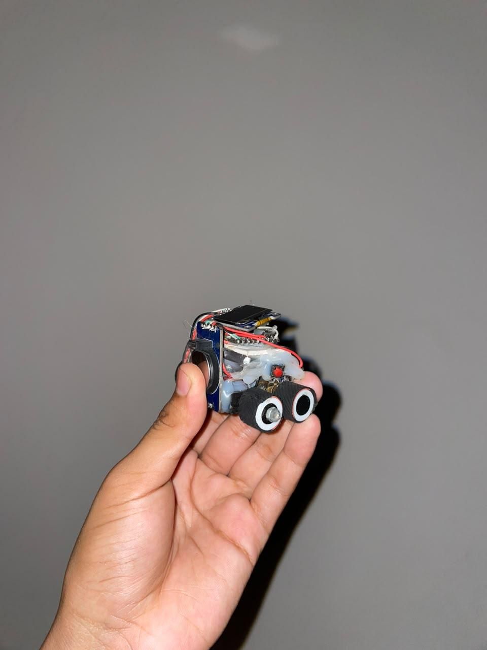
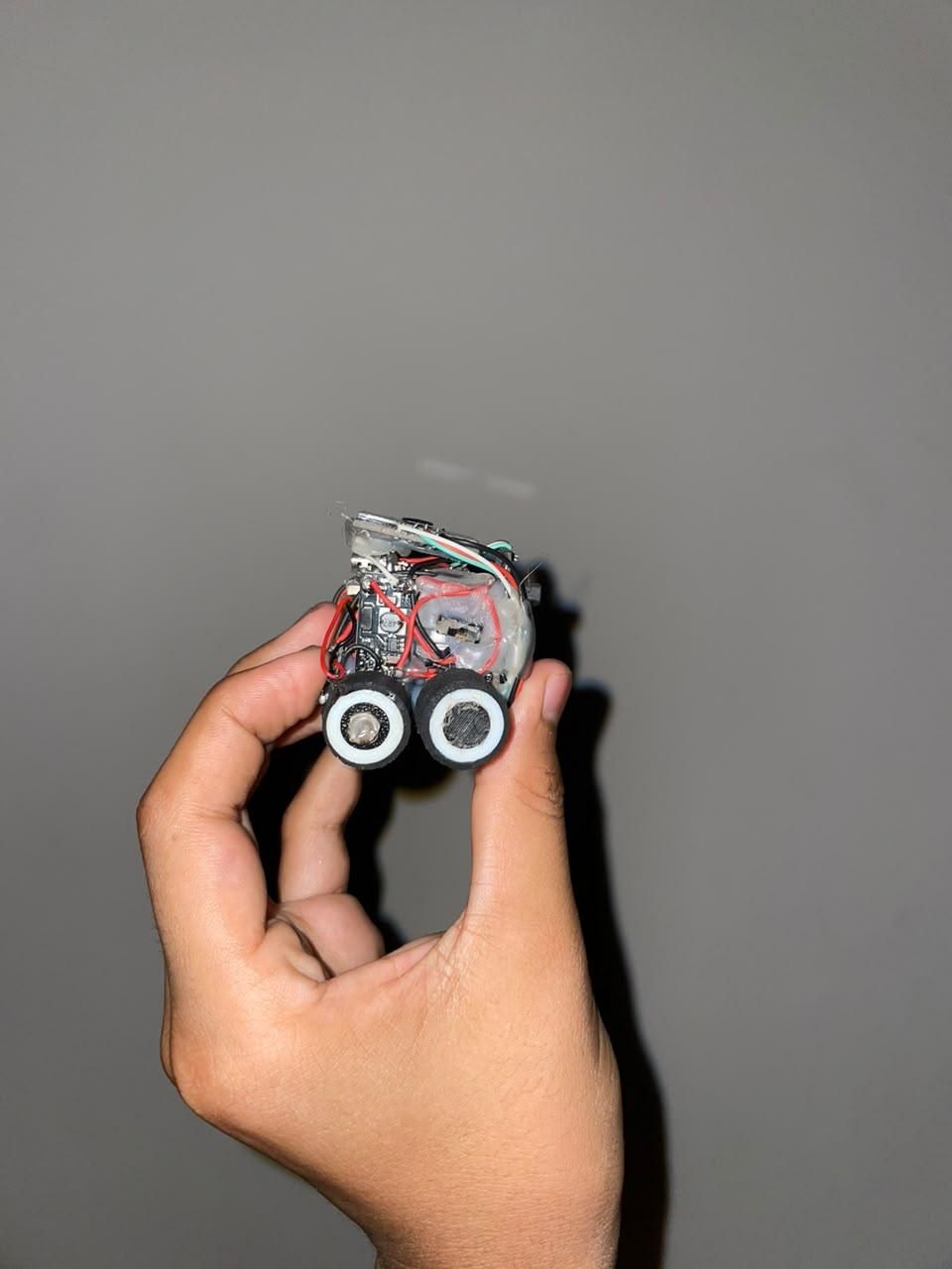
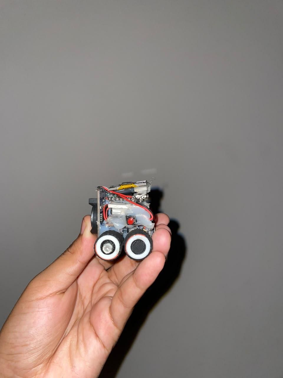
Voila, our 'MS_RCWATCH' v1.o is ready to be programmed.
CODE
The bot is programmed in 'ARDUINO IDE'.
Downloads
CODE-IMP
1. Nordic UART Service UUIDs (top of file)
Why it's essential
These specific UUIDs are pre-registered by Nordic Semiconductor and hardcoded into most BLE terminal apps already on the market.
The Payoff
Because you used these exact values instead of generating your own random UUIDs, apps like nRF Connect or Serial Bluetooth Terminal auto-recognize the service the instant they connect and label the characteristics "RX"/"TX" for you. Change even one character in these UUIDs and that auto-detection disappears — you'd be stuck writing your own phone app just to talk to the board.
2. Direction-Aware Motor Driver
The Mechanic
The MX1508 has no dedicated "direction" pin per channel — direction is entirely encoded in which of the two input pins receives the PWM signal.
The Trap
If you tried to reverse a motor by just writing LOW to both pins and expecting some other magic, nothing happens — the driver chip needs one pin actively high (PWM) and the other actively grounded to establish current flow in either direction. Get the pin roles backwards and the motor either doesn't spin or spins the wrong way for every command.
3. Ramping on Every Speed Change, Not Just Startup
The Risk
Turning commands (L/R) spin one wheel forward and the other backward at the same instant. That's actually a larger combined current draw off the battery than driving straight, because both motors are under load in opposite directions simultaneously.
The Fix
The original code only ramped power on motorsForward(). This version routes every direction/speed change — forward, reverse, turning, stopping — through the same step-by-step ramp, so the TP4056's overcurrent protection never gets tripped by a sudden turn command either.
4 . BLE Callbacks Run Outside loop() Entirely
The Mechanic
This function is not called by your loop() code — it's invoked by the ESP32's BLE stack on its own internal FreeRTOS task, triggered the instant the phone writes a byte.
The Trap
Because of this, motor commands keep working even while loop() is sitting inside a delay() doing nothing else — the callback interrupts independently. But it also means this function needs to stay fast and non-blocking; if you put a delay() or a slow loop inside onWrite(), you stall the Bluetooth radio itself and the whole connection can drop.
5. Re-Enabling Advertising After Disconnect
The Risk
BLE peripherals automatically stop advertising themselves once a central device (the phone) connects — that's normal behavior, not a bug.
The Trap
If this line were missing, the very first time your phone disconnects (walk out of range, close the app, etc.), the ESP32 would go permanently invisible to Bluetooth scans until you power-cycle it. This one call is what lets you reconnect over and over without ever touching the reset button.
6. Locking Out the Rest of loop() During BLE Control
*And I am very sorry for the app, because for controlling this car I was trying to make a custom app but in short I failed.*
DIAGRAM
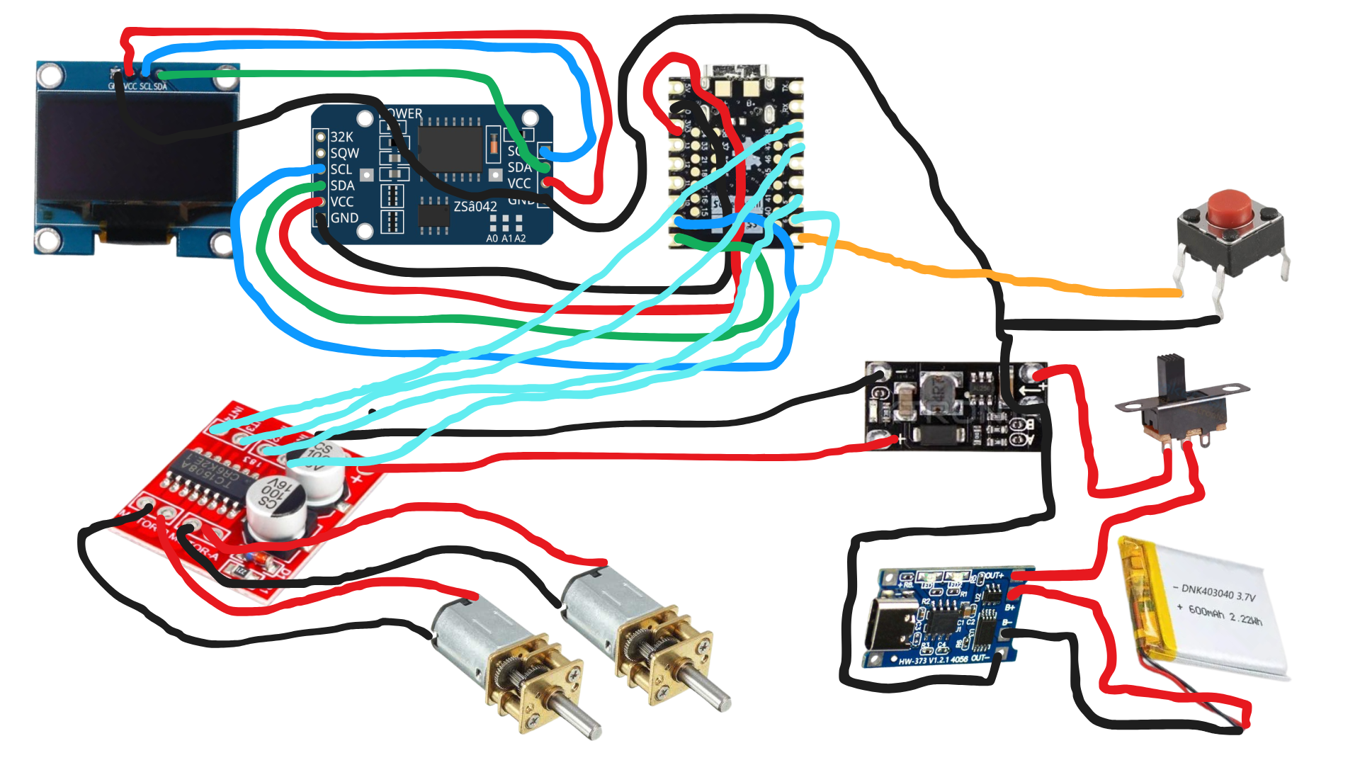
Make sure the grounds of the Arduino, MX1508, Battery. *Sorry for the inconvenience in the circuit*
CONCLUSION
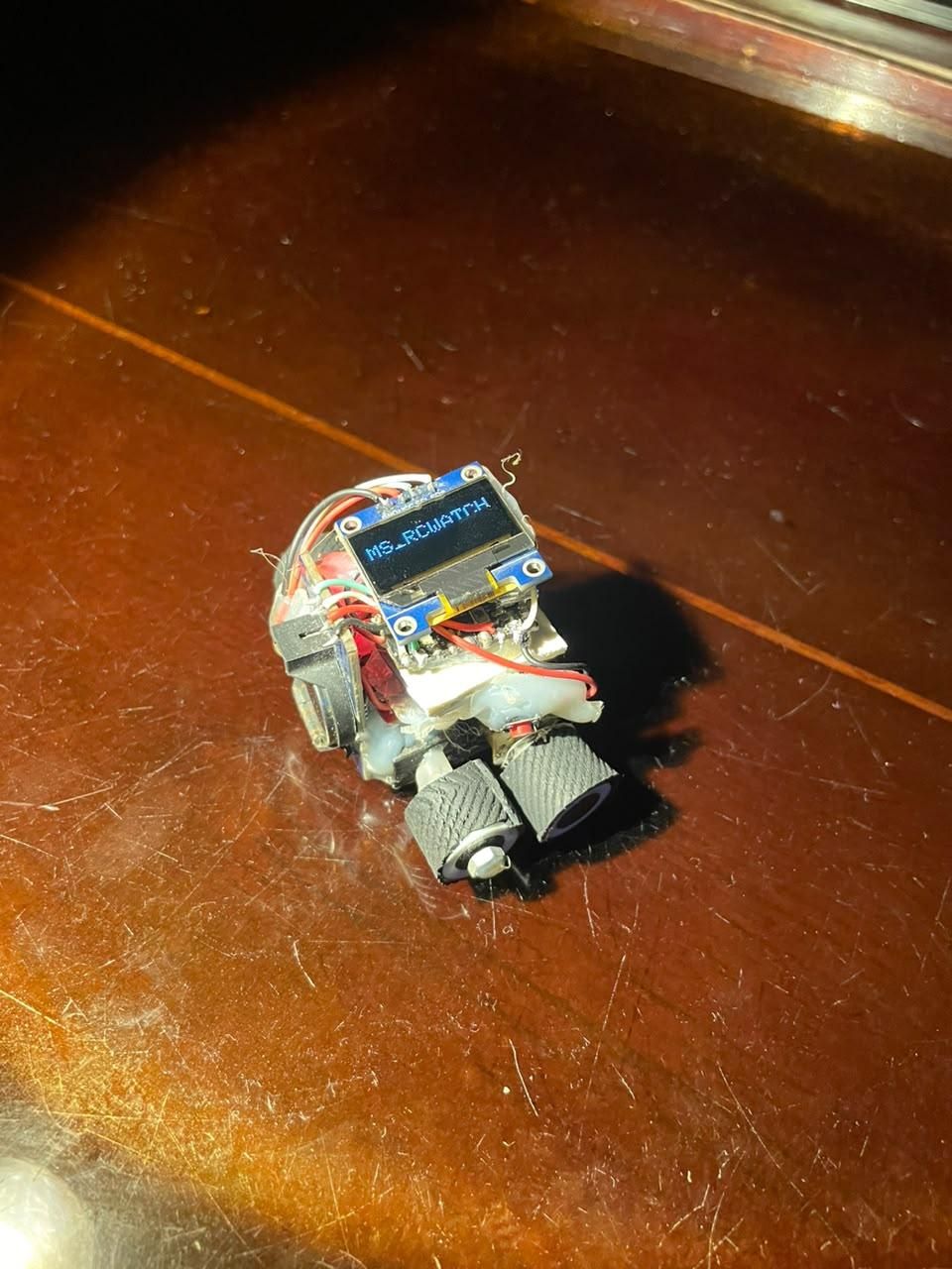
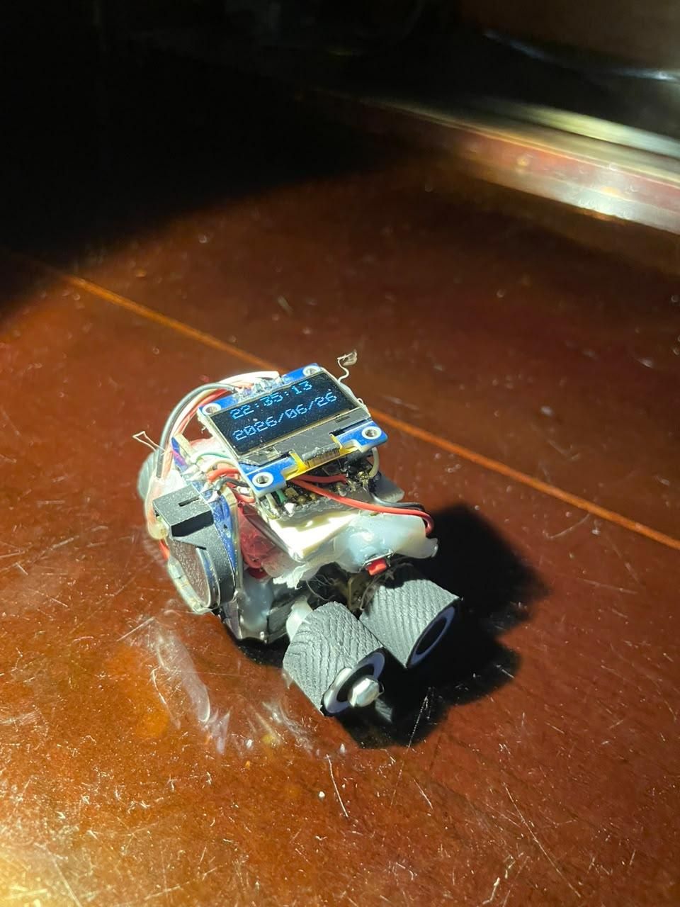
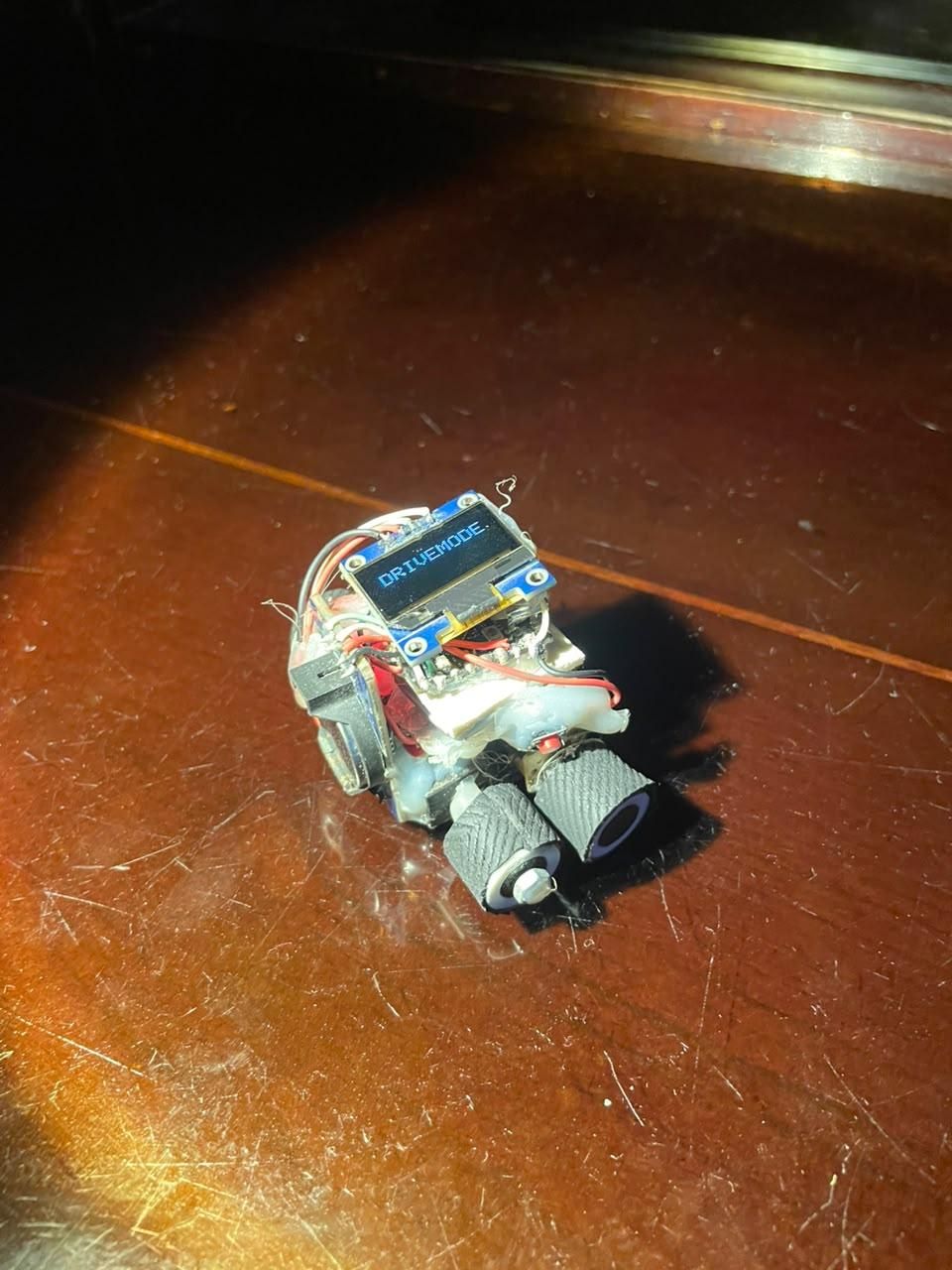
THE FUNCTIONS OF 'MS_RCWATCH':
- It wakes up when the button is pressed any while the watch is on, if the button is pressed again it switches to drive-mode and then you can connect it to your phone and control.
- It gives you a precise time.
- Very small in size.
- No jitter in driving, smooth.