MagSafe StudyTimer: Makes Studying 3% More Enjoyable
by hex-255 in Circuits > Electronics
4246 Views, 22 Favorites, 0 Comments
MagSafe StudyTimer: Makes Studying 3% More Enjoyable
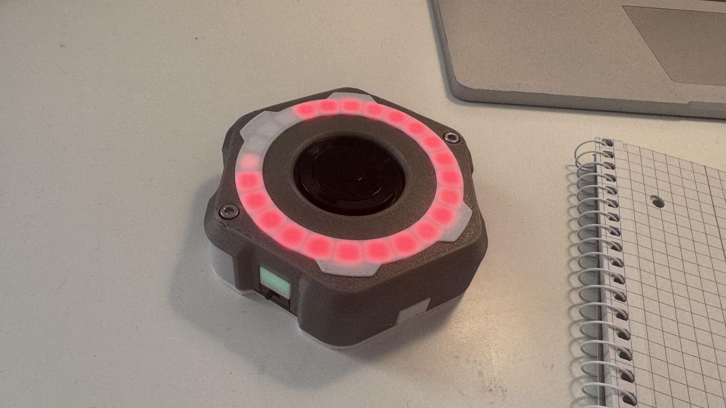
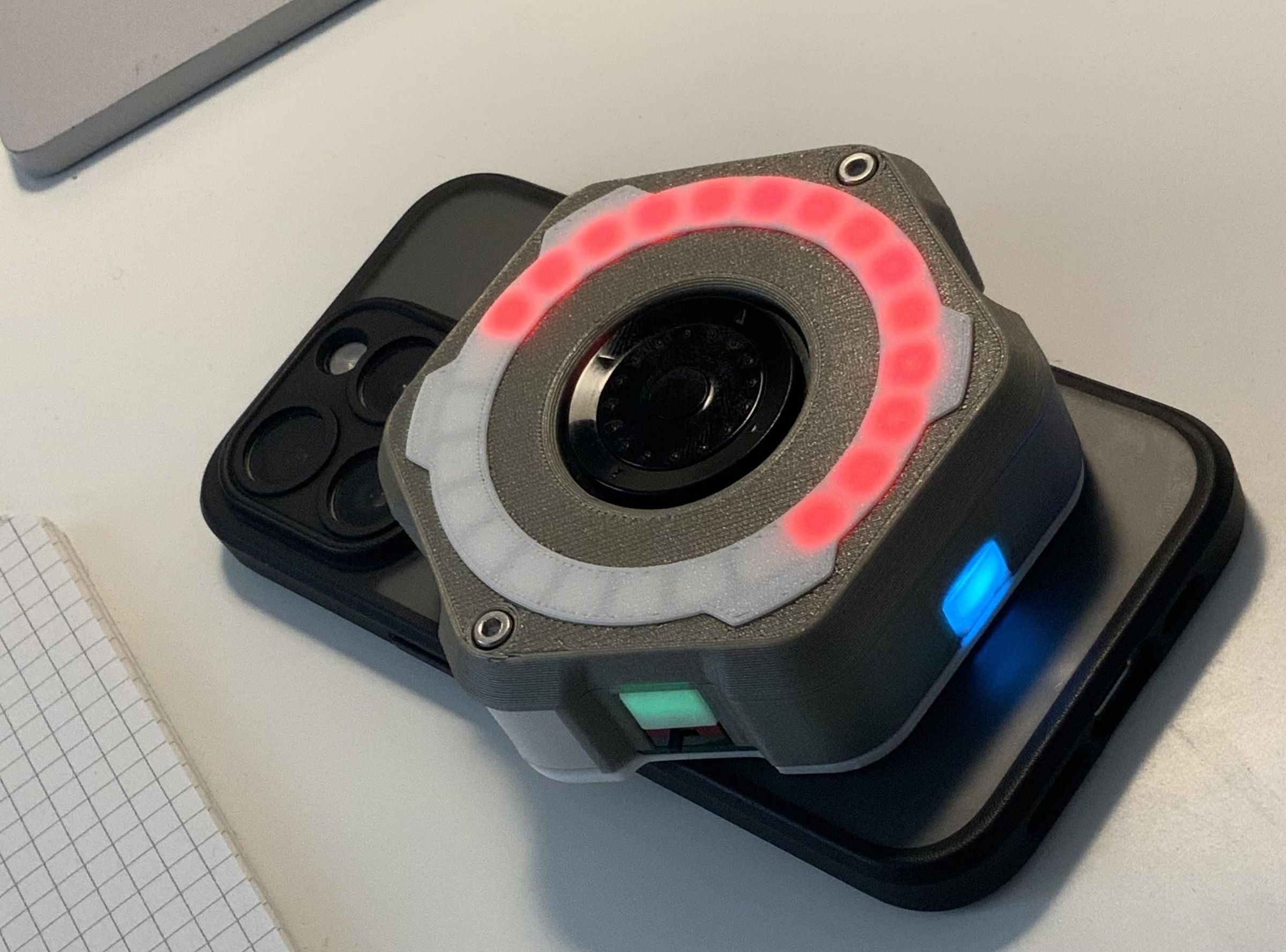
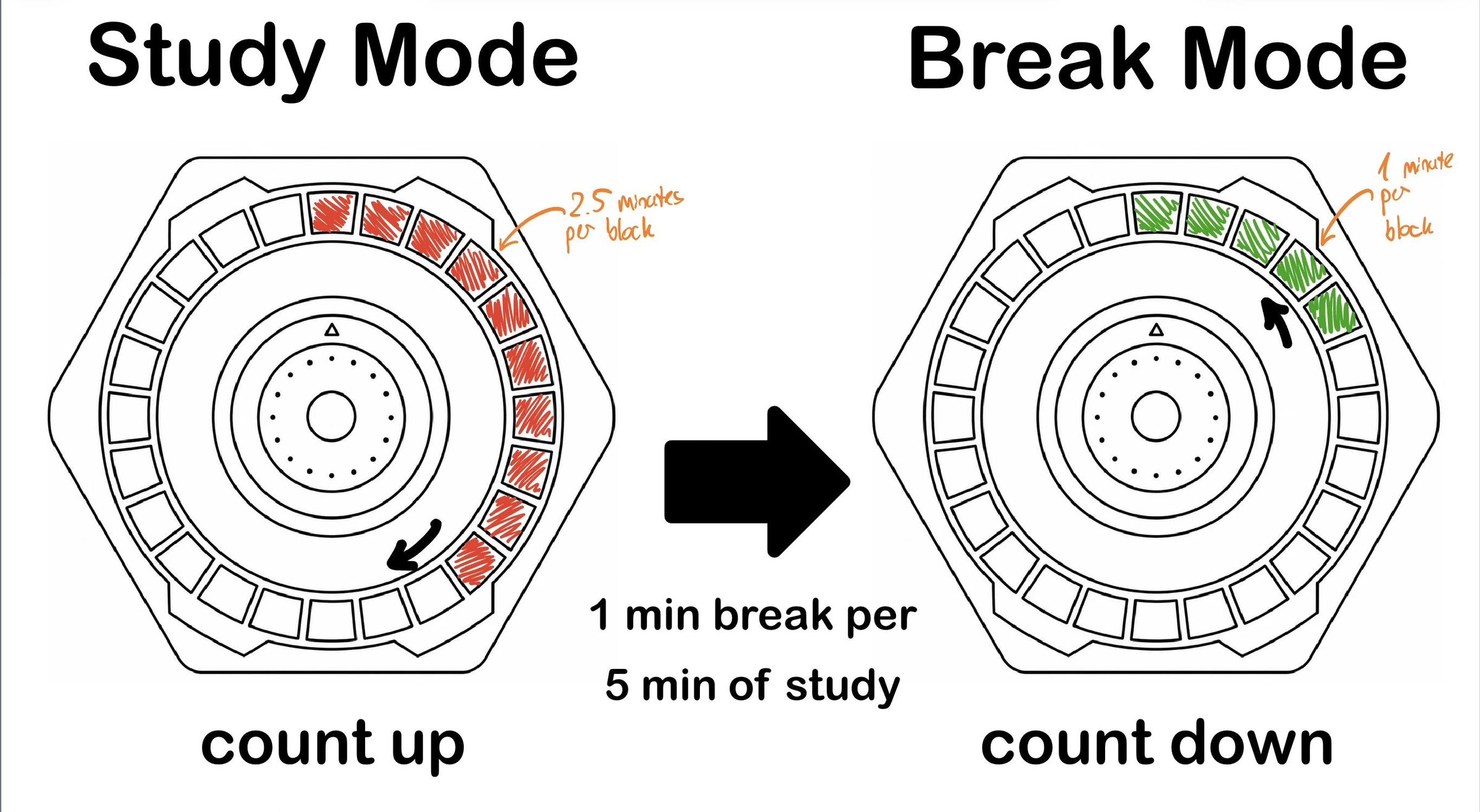
A study timer that calculates the allotted break time depending on the time you spent studying. A longer break can be earned through a longer study interval. 5 extra minutes of focus gain 1 extra minute of break. The current timer state is visualized through an LED-ring with 24 Neopixels that pulsates to show the current progress.
Additionally the timer has a MagSafe ring and a hall sensor embedded in the base. Meaning it can be docked onto the back of the phone and detect it's presence through the magnets. Trying to go on your phone will lead the hall sensor to lose contact to the magnet and the timer to stop. That way the study timer can effectively keep you from using your phone while studying!!
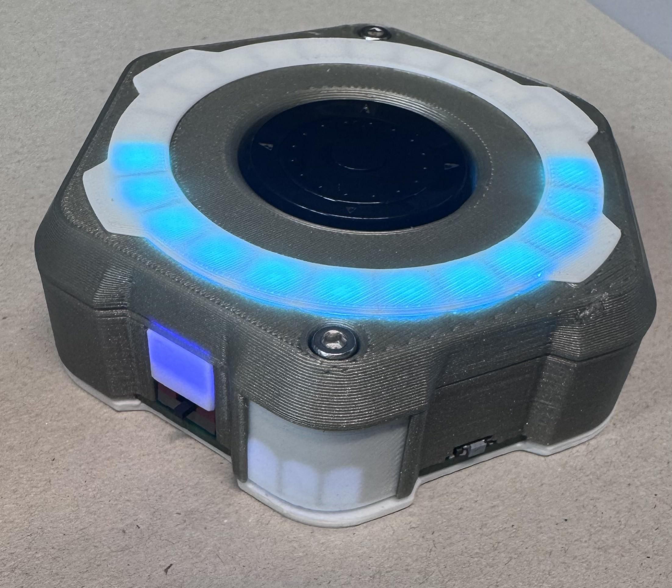
If the user is starting a new study session shortly after the break ends, effectively complying with the rhythm specified by the timer, the timer is able to count up streaks. The streak is visualized through white LEDs that shine through a diffuser part on the side of the timer. (see picture above).
As a user interface the timer contains an Ano Scroll wheel which includes 5 buttons plus a rotary encoder. Two shoulder buttons are added aswell. The formfactor is inspired by this device from Adafruit: LINK
All files for the StudyTimer are available on Github through this link.
Supplies
- M3x18 screw (2x)
- M3x12 screw (2x)
- M3 nut (4x)
- LiPo battery with battery protection circuitry included (max. dimensions: 50mm x 29mm) (I used these ones with 1100 mAh Link)
- MagSafe ring (Link , inner diameter: 43 mm; outer diameter: 57 mm)
- printed parts:
- Bottom
- Middle
- Top
- Diffuser
- Magnet_White
- SlideSwitch_White
- Streak_Cover_Flat
- Custom PCBs:
- TOP
- BOTTOM
- Cable for connecting both PCBs (part number: A08SR08SR30K51B (available on Digikey))
System Overview
 (1).png)
.png)
.png)
The study timer is built up from two custom PCBs. The KiCAD files to both can be found here: KiCAD.
A full system diagram containing all components is provided above.
The bottom board contains a section for power management. A fuel gauge IC keeps track of the battery's state of charge. A buck-boost converter generates a constant 3.3 V for the microcontroller and all other peripherals. This supply voltage can be cut in sleep mode through a load switch to minimize the power draw on the battery. (The power draw while the ESP is in sleep mode comes out to around 5 mA - measured with Power Profiler Kit II.) To charge the LiPo battery through the USB-C port a charging IC is added.
One IO expander allows the reading out of two shoulder buttons, the hall sensor and a switch used for enabling and disabling of audio feedback through a buzzer. Another IO expander controls the 8 LEDs used for visualizing streaks through counting up.
The top board is connected through a fine-pitch cable. It contains the 24 LEDs of the ring used for counting and the Ano scroll wheel that houses five buttons and a rotary encoder in a compact formfactor. The Ano scroll wheel is managed through a separate microcontroller that is running Adafruit Seesaw framework.
PCB Fabrication
.PNG)
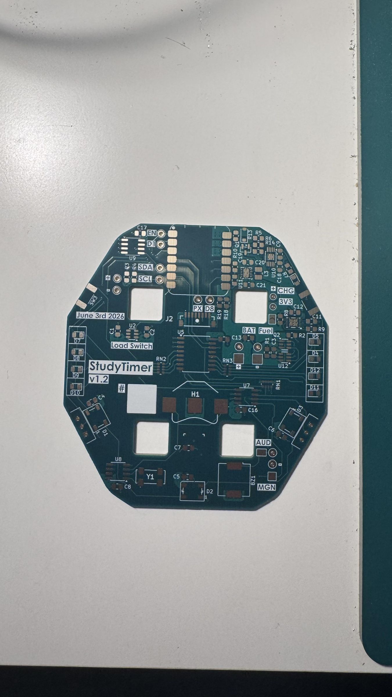
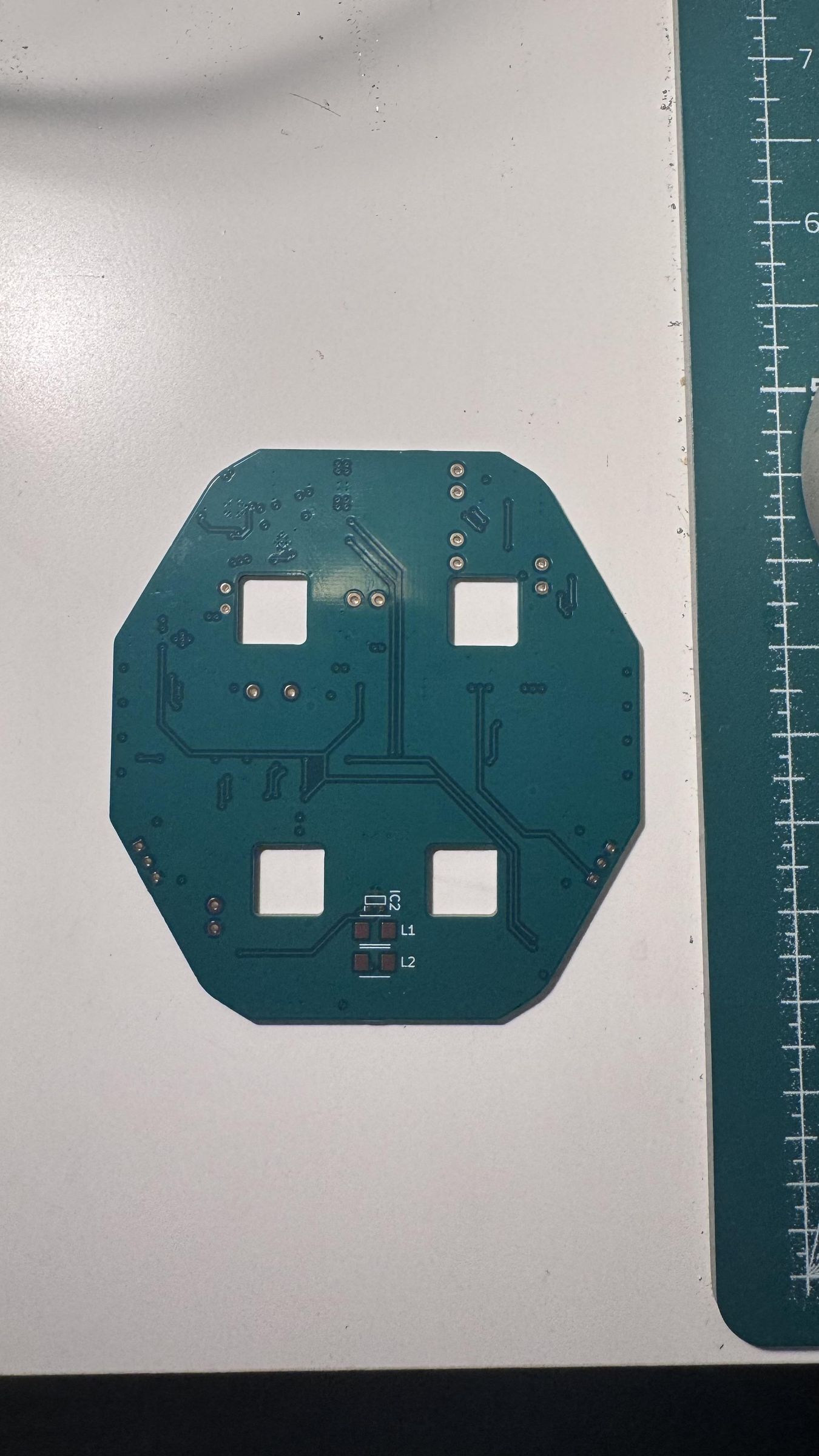
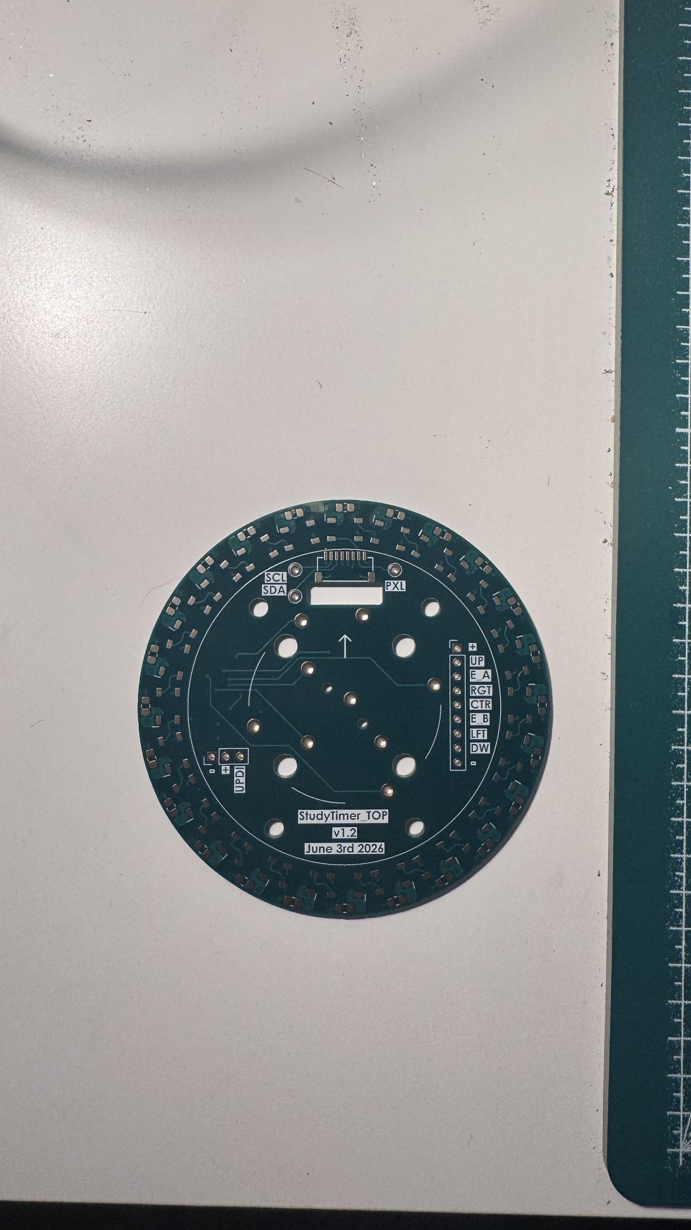
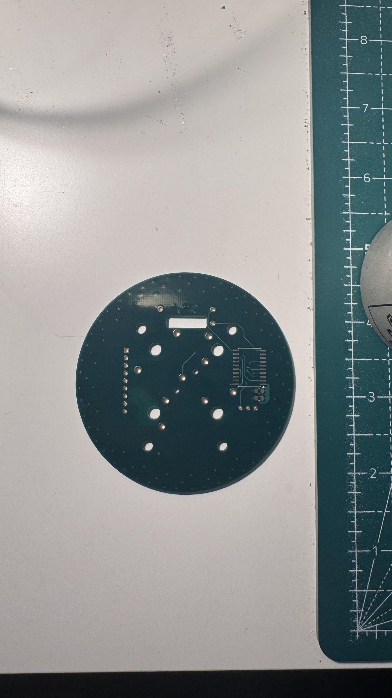
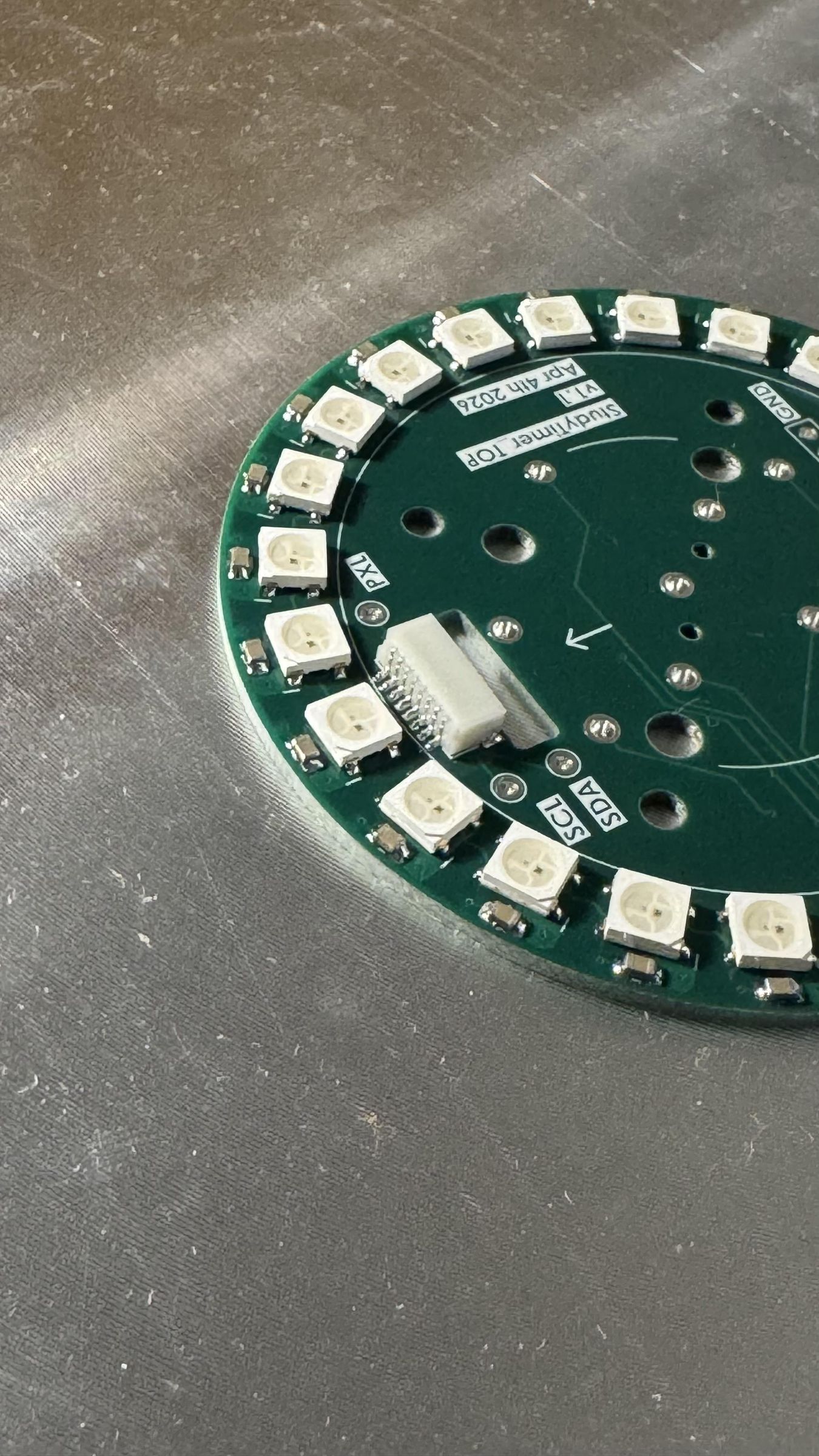
The gerber files for ordering both PCBs can be found here: Gerbers.
To make sourcing easy all non-standard parts have their part number noted in the HTML BOMs: BOM files.
All parts are available through Digikey.
Due to the small-pitch ICs used for Power Management on the BOTTOM PCB I recommend using solder paste and a hot plate for soldering the PCBs of the project. Stencils are only necessary to buy for the top side of both the TOP and the BOTTOM board since there are only a few components on the bottom side of each PCB. Those can easily be soldered by hand to save some cost on stencils.
There are two fixes needed on the bottom board to have the PCB fully functional. A pull-down resistor (around 10 kOhm) is needed on the load switch control signal and the on-board battery protection needs to be bridged through a jumper since it does not work correctly. (Note again to use a LiPo battery that has protection circuitry included as mentioned in the Supplies section.) Both fixes with solder locations are marked in the screenshot above.
Upload Firmware
The firmware for the ESP32 on the bottom board can be found here: ESP32
The Seesaw firmware for the Attiny that reads out the scroll wheel can be found here: Seesaw
There are three jumpers on the Top PCB that allow the Attiny to be programmed over UPDI. I used the UPDI friend from Adafruit for programming. Here is a tutorial.
3D Print Parts
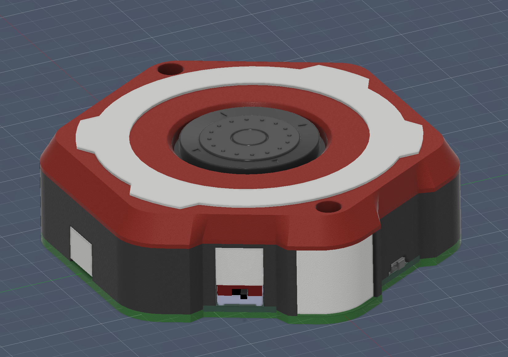
The printed parts needed for the enclosure are here on Github: STL
There are three structural parts called Bottom, Middle and Top.
The other four parts should be printed white since they act as diffusers for LEDs:
- Diffuser
- Magnet_White
- SlideSwitch_White (print twice)
- Streak_Cover_Flat (print twice)
Prepare Base Part
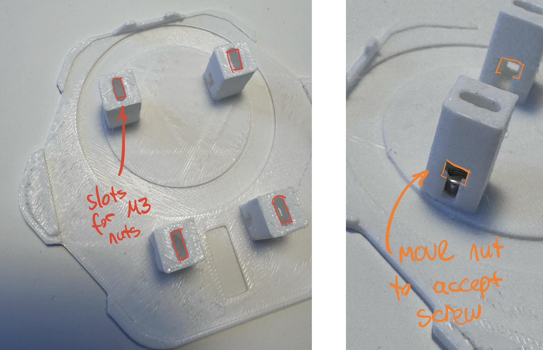
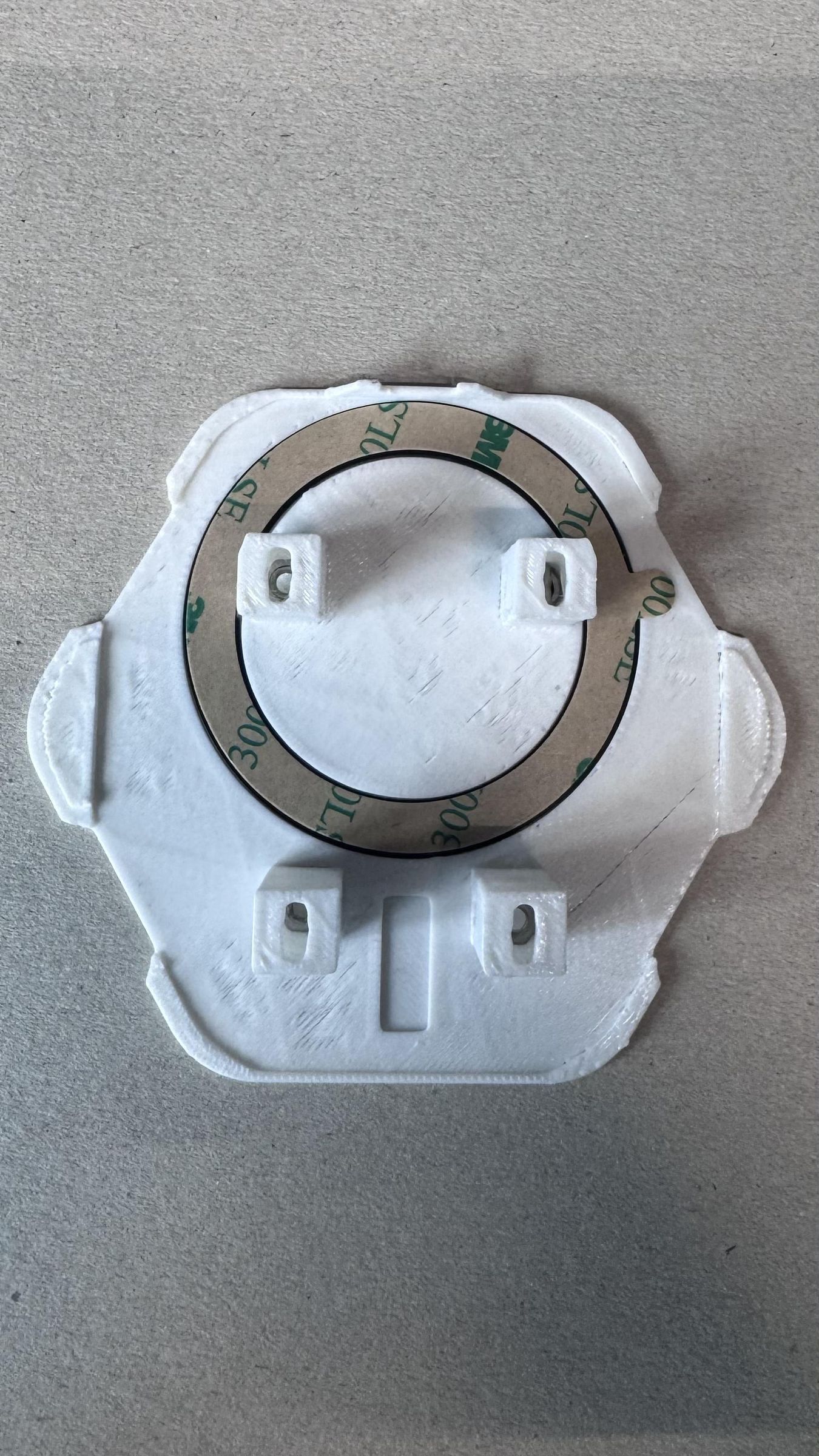
The first step of the assembly is to place the magnet ring in the cavity of the Bottom.stl part.
Then the M3 nuts should be dropped into the part using the slots that are highlighted in red in the picture. They then need to be flipped over to accept the screw. The orange opening marked above is wide enough for the hex key to enter. Push the hex key through and rotate the nut to lie flat in the printed part.
It is not necessary to place four nuts in the part the secure the PCB later two are enough.
Place Bottom PCB
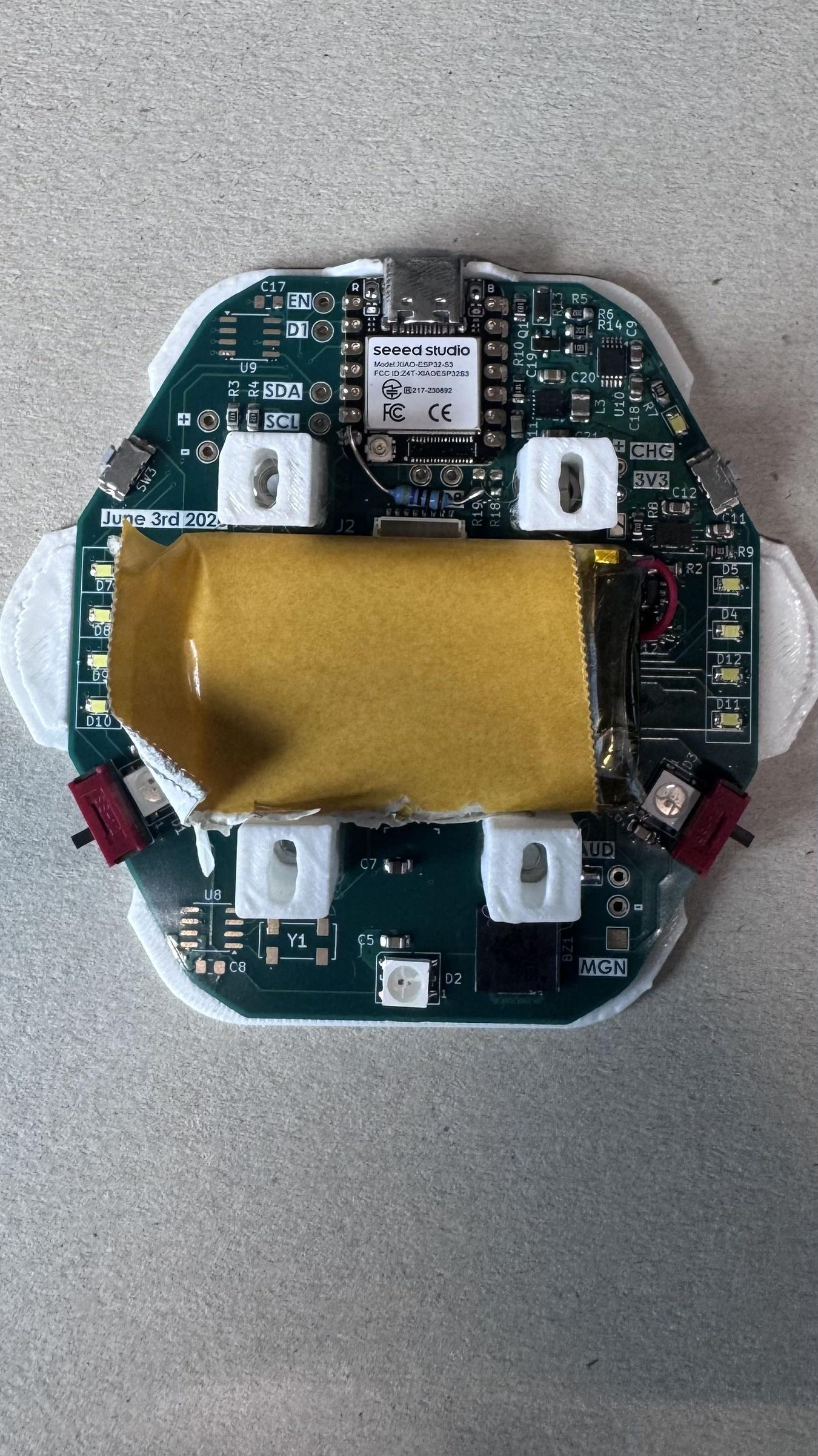
Next the Bottom PCB should dropped onto the Bottom.stl part.
Connect the battery to the PCB through soldering onto the labeled pads.
Adding double-sided tape to secure the battery is recommended.
Connect Top PCB
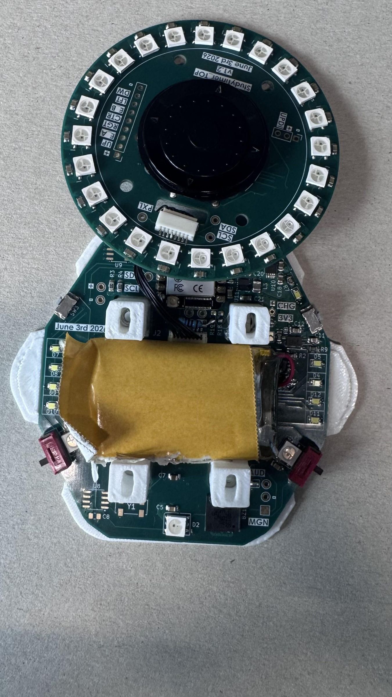
Connect both PCBs through the use of the cable.
Prepare Middle Part
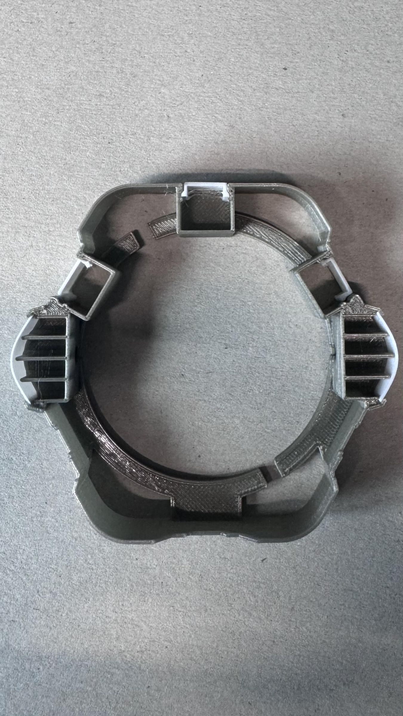
Drop the white parts used for diffusing in the slots of the Middle.stl part. The streak covers need to be bent in shape to fit.
Note the cutout in the middle part that allows the Top PCB to be fed through in the next step.
Place Middle on Bottom Part
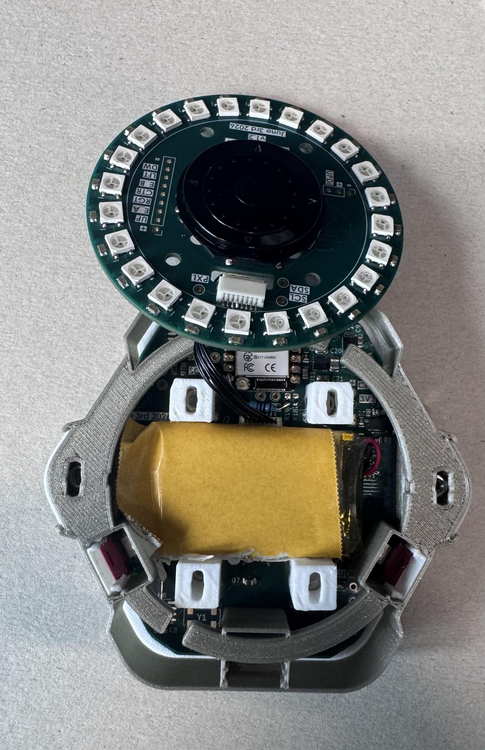
Next step is to place the middle.stl on bottom.stl while making sure that alignment is correct and the Top PCB passes through to be placed on top later.
Add the two remaining nuts inside the cavities on the side of the middle.stl part. Align them in the same way we did for the bottom.stl.
Secure Top PCB
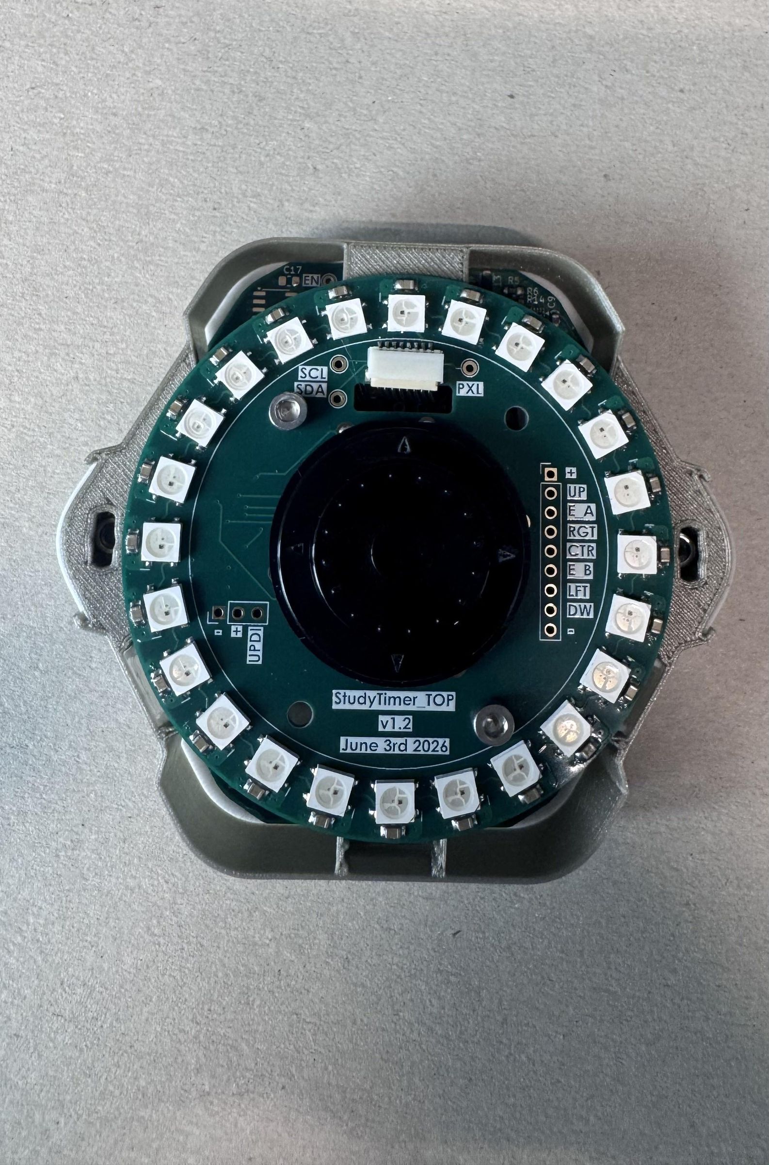
Use the two M3x18 screws to secure the Top PCB onto the timer
Finish Assembly by Securing Top Part
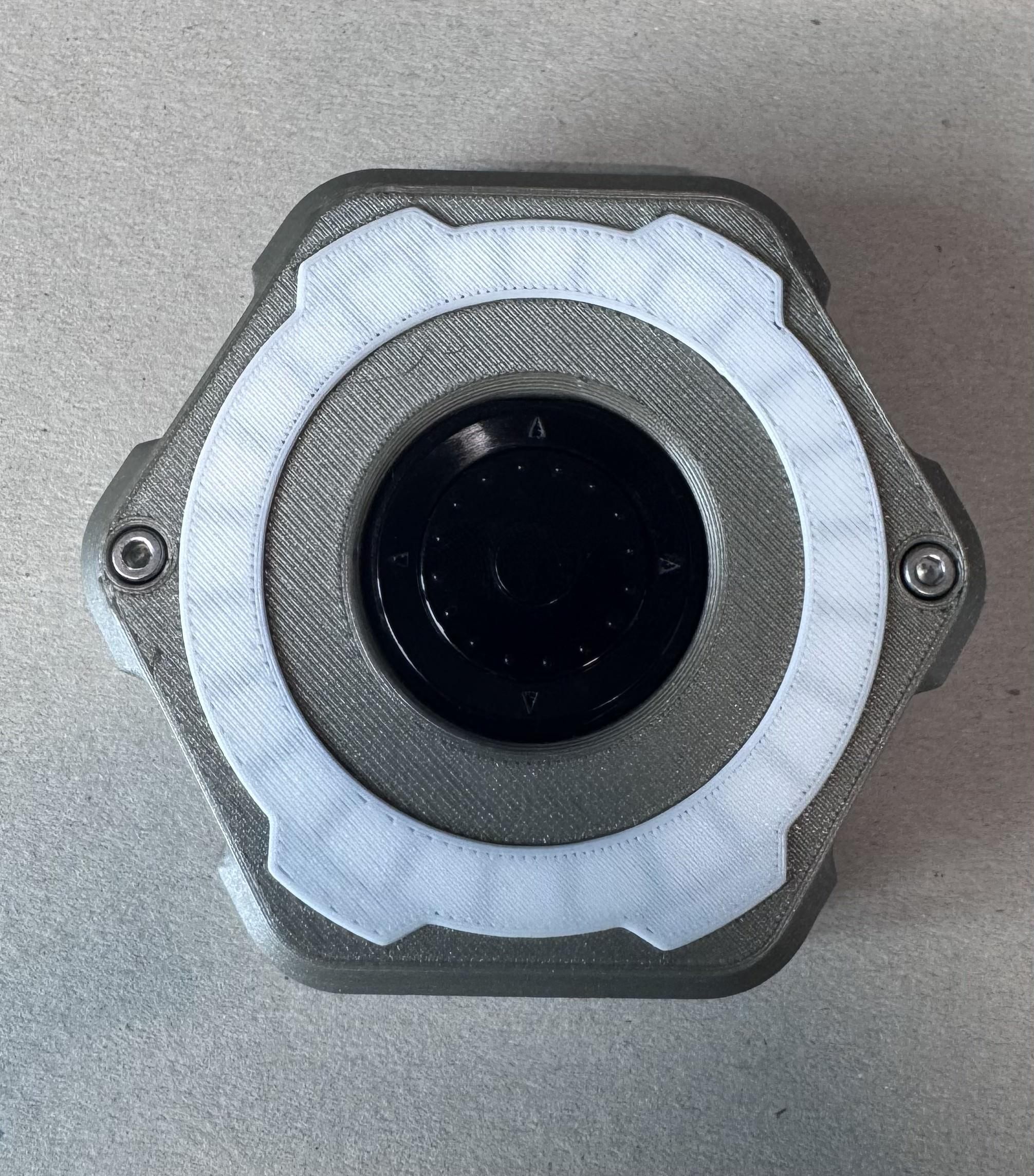
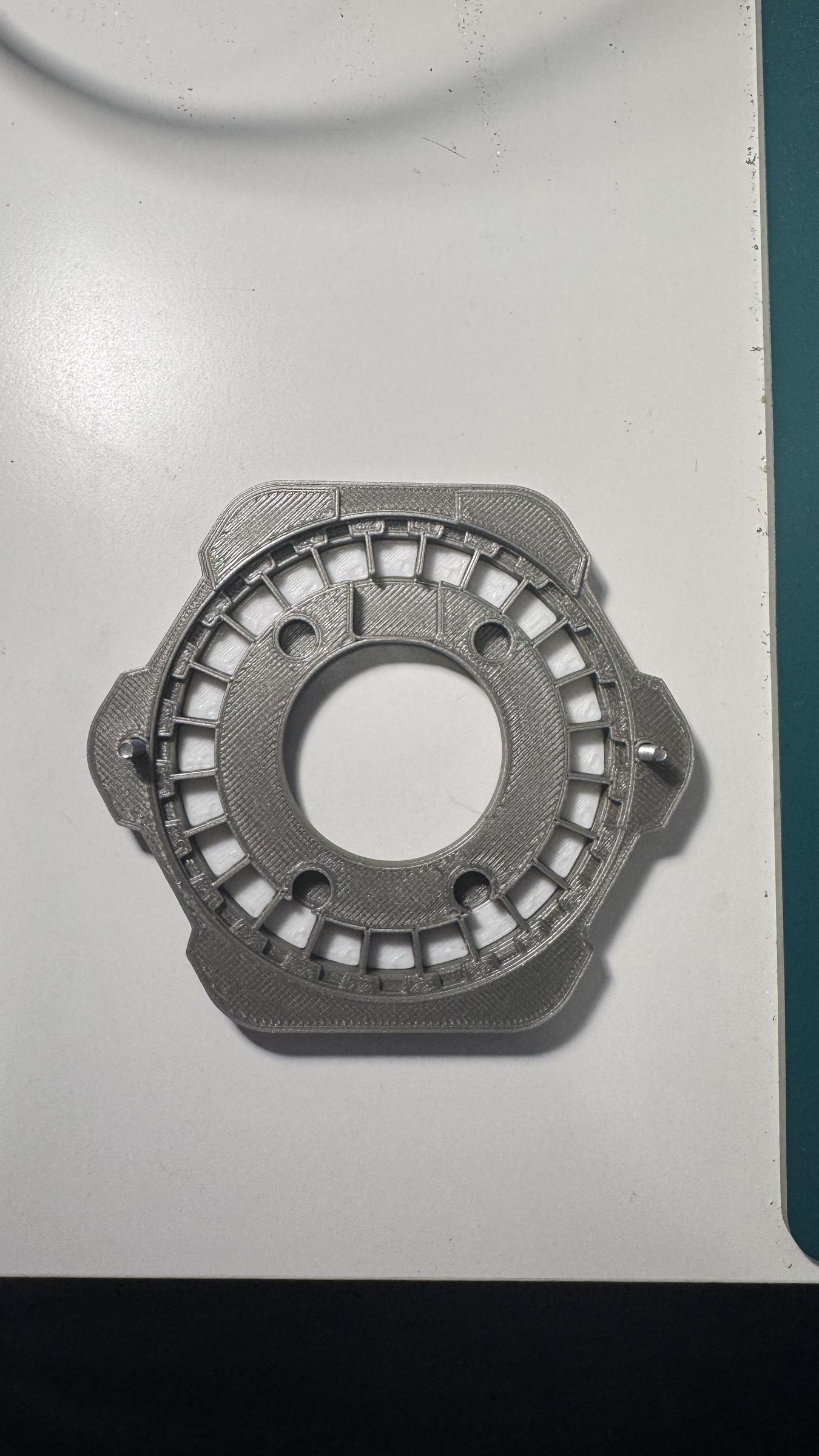
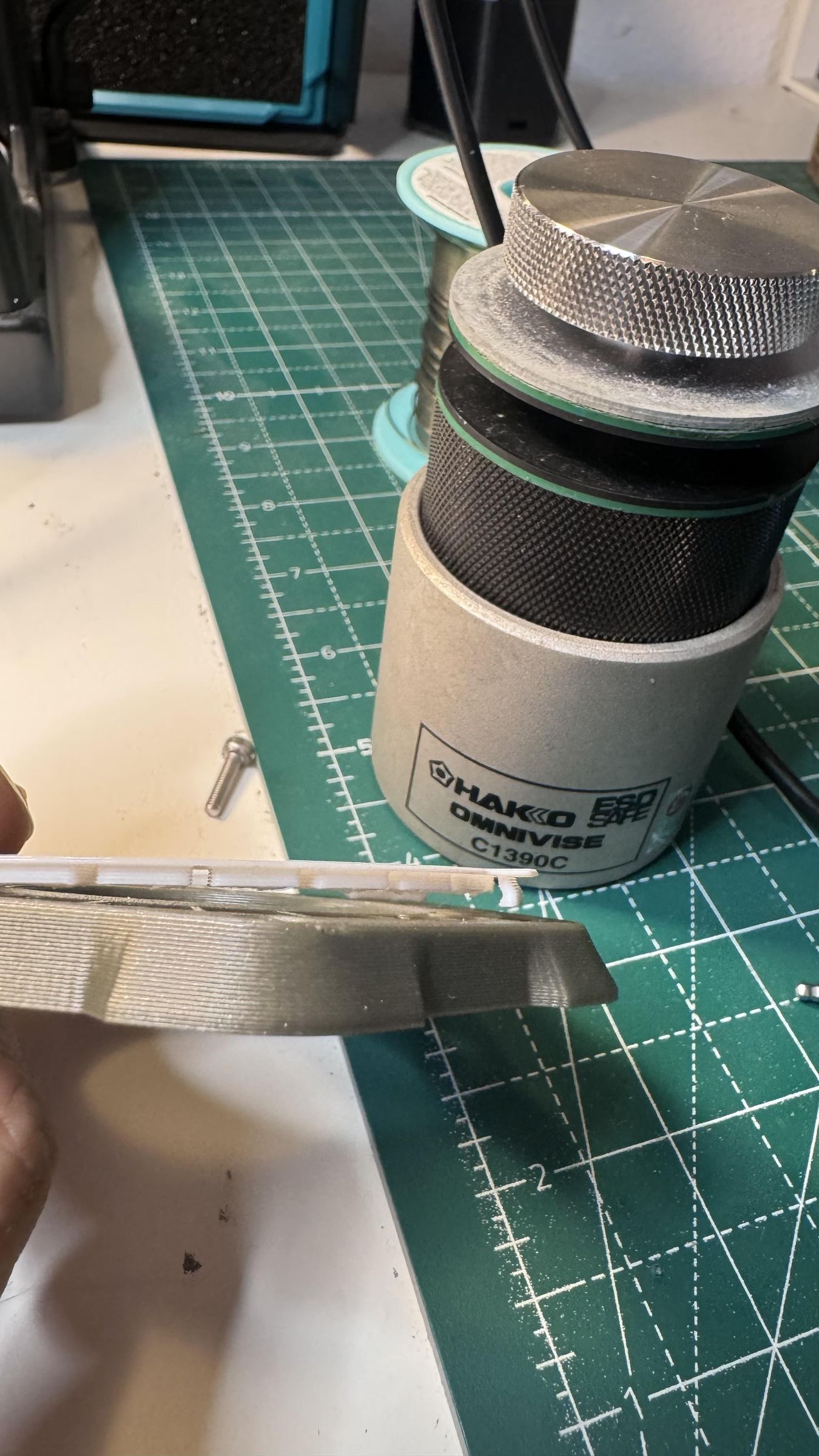
Place the Top.stl part on around the TOP PCB. The printed part has a cutout for the cable connector that decides the orientation of the part.
The 2 M3x12 screws are used to connect the Top.stl part. Note that the holes are closed by a thin layer of plastic that needs to be broken away with the screw.
The diffuser.stl part can be clipped in as a final step.
Usage Instructions
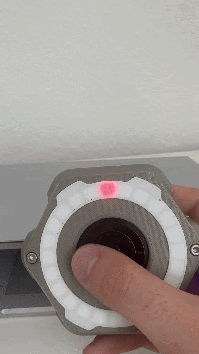
The slide switch on the bottom left of the timer wakes up the device. Immediately after startup an animation on the ring shows the battery's state of charge. Then the timer enters the main menu.
In the main menu a pixel on the LED ring can be moved through the rotary encoder, the two shoulder buttons trigger an impact animation and pressing the UP button cycles through pre-set colors. Making the study timer a great fidget toy for short breaks. See the GIF for a demonstration.
Pressing the LEFT button of the scroll wheel while in the main menu enters the mode selection menu. The user can select between the unlimited and the fixed study mode. After selecting the fixed mode the user can choose between the options of 50-10 and 25-5 as study-to-break-ratio. In unlimited mode the break has to be started manually.
To control the brightness of the LED ring press the RIGHT button from inside the main menu. In the brightness menu the status LEDs on the bottom PCB can be disabled aswell.
Pressing DOWN while in the main menu enters the debug mode. In this state one block counts up in only 5 seconds making it a great way to demonstrate the working principle to other people.
There are three status LEDs on the bottom board behind 3D-printed diffusers. The left most one is the power LED. It shows the state of charge in green, yellow or red. The middle status LED visualizes if a phone has been detected through the MagSafe magnets. If yes it turns light blue. Starting a study session while the timer is placed on a phone enables strict mode. In strict mode the magnet status LED turns off, then yellow and then red until leading the whole study session to stop if the phone is moved away from the timer. The right status LED is used to show if the audio feedback is enabled. It's orange if audio is enabled and blue if not.
The LEDs behind the rounded corner of the timer are used to count up streaks. Add one to the streak by studying for more than 20 minutes and then starting a new session in less than 5 minutes after the allotted break ended.