Make Your Own ChronoGlobe 🌎⏰!
by Lina Maria in Craft > Printmaking
2149 Views, 44 Favorites, 0 Comments
Make Your Own ChronoGlobe 🌎⏰!
.png)
Welcome to the Instructable for creating your very own ChronoGlobe, a globe clock with rotating hour lines! Have you ever had an idea simmering in your mind for years, waiting for the perfect moment to bring it to life? That's exactly how I felt about this project. For quite some time, I've been captivated by the concept of a globe clock that displays the time across different time zones with rotating lines. Finally, I decided to roll up my sleeves and turn this vision into a reality. Join me on this journey as we delve into the intricate process of crafting a functional and visually striking ChronoGlobe.
Supplies
- Nail glue
- 3D filaments
- Acrylic paints
- Adhesive paper
- Plastic primer
- Bearings (4mm x 9mm)
- Small cables
- Antenna of an old radio
- Plastering compound
- 24-hour clock mechanism
Sketching

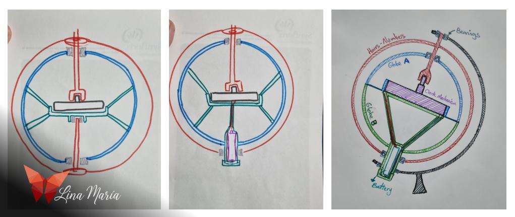
I needed to find a solution for creating the internal mechanism of the globe, so I spent some time sketching until I found the design that I believed would work best, which is the one you will see in this instructable.
The Idea

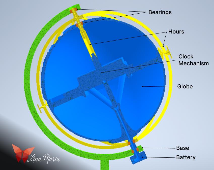
I find it amusing to showcase these images in the initial steps, before getting into the creation process. However, this time around, I considered it prudent to start with the "end," presenting the assembly of the various modeled elements to give you an insight into what I had envisioned when I began the project.
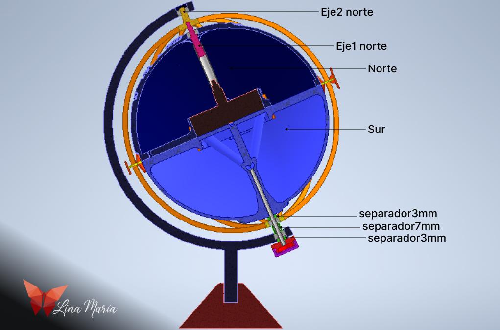
I used four different colors in these images to distinguish between assemblies that are fixed and immobile from those that allow movement. Thus, although the base consists of two pieces in reality, here it appears entirely green. In orange, you'll see the bearings that enable movement between certain parts. The yellow section is assembled with the clock mechanism at the hours, which will cause the vertical lines we see on the globe and the equator line to rotate. Finally, in blue, we have the terrestrial globe, with internal supports to hold the clock mechanism and the battery, which I placed externally for easy replacement when needed.
The Globe
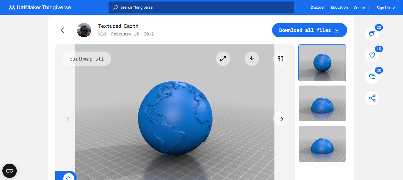
For the globe, I had several options. I could obtain a sphere, cut it in half, and paint it, or use an existing terrestrial globe or print one of the many available for free online. Ultimately, I opted for the one I found at this link: https://www.thingiverse.com/thing:17336. However, I wasn't entirely satisfied with the idea of printing it and then assembling the entire mechanism separately, so I decided to edit it instead.
Editing the Globe:

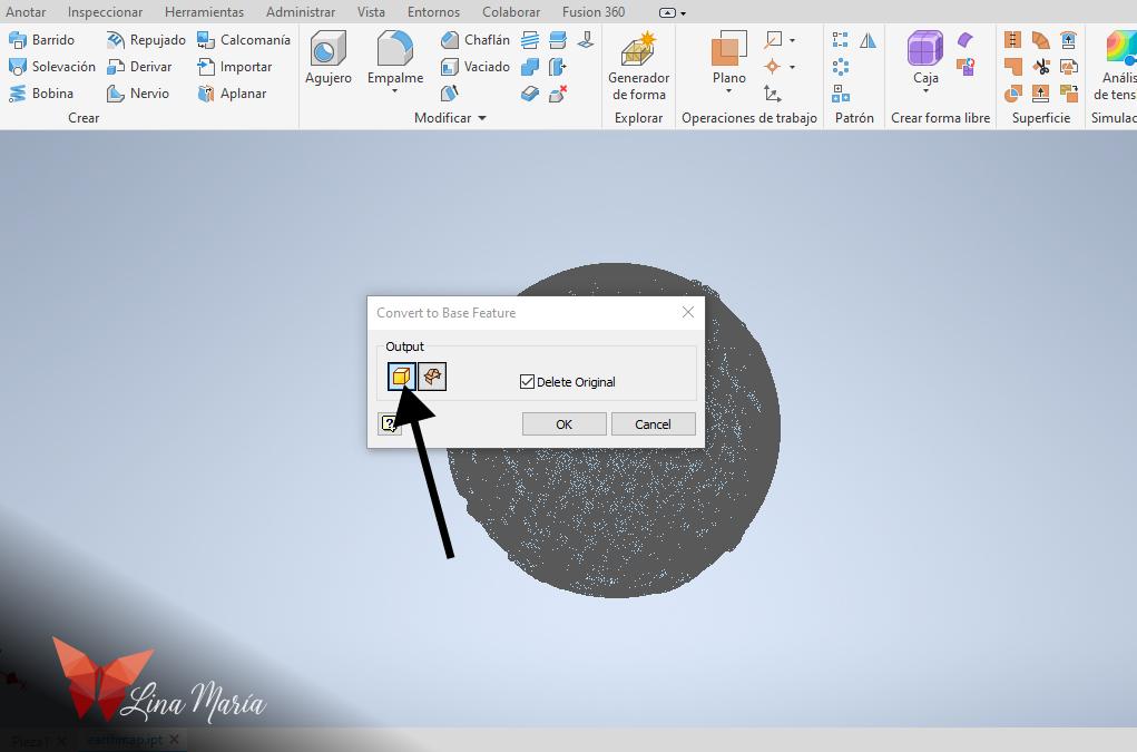


I opened the STL file in Inventor, then right-clicked on the part in the list on the left side and selected "Convert to Base Feature." In the subsequent dialog box, I chose the "Solid" version. After reviewing the dimensions of the globe and finding them too large for my intended project, I saved the file. Then, I created a new file and used the "Manage" option to click on "Derive." From there, I searched for the saved file and scaled it to achieve a diameter close to 15cm.
*The names of the actions in Inventor may vary, as I'm using a generic word for translation, and I work with the software in Spanish. In case of any doubts, the images can precisely show the options I selected.
North Hemisphere

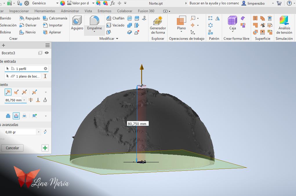

- I created a void sphere inside the globe to hollow it out.
- Then cut it horizontally in half, saving the upper half as the north and the lower half as the south.
- I made a hole in the center for the bearing.
The Clock


I took the measurements of the clock and created a space for it within the piece, adding several supports to ensure the structure keeps it centered.
* For this project I used a 24-hour clock mechanism. Years ago when I started thinking about this idea, that was one of the things that had me stuck, figuring out the internal mechanism to switch from 12 to 24 hours. Then, while browsing some technology stores in my city, I saw a clock mechanism that displayed 24-hour time, so I bought it thinking that someday I would do this project.
This is not the one I bought... but an example I just found online https://www.clockparts.com/24-hour-high-torque-movement/
Southern Hemisphere


For the southern hemisphere, I created a rectangle against which the clock will rest and added tubes to allow two cables to pass through, reaching the points where the battery usually sits within the clock mechanism. By passing these cables through the center of the axis, we'll be able to leave the battery on the outside, making it easy to replace when needed.
Corners
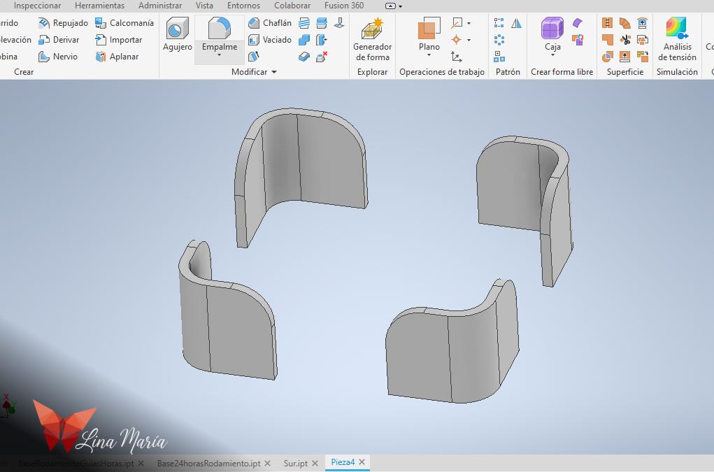

I created these elements for gluing them to the southern hemisphere, serving as guides when I join the two parts of the globe together.
Hour Lines


For the hour lines, I drew a circle slightly larger than the globe and offset it. Then, I cut it in half. I created the pieces that would go above and below, supporting these "lines". For the upper piece, I designed it to be joined to a component connected to the clock mechanism, allowing the lines to rotate around the globe according to the hours. I left the lower piece hollow with the size of a bearing so it can rotate freely below. Then, I subtracted these spaces from the curved figures I initially created. I also created the horizontal line and the pieces that will hold the hour numbers.
Base
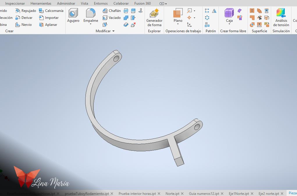
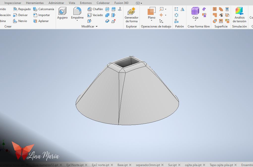
Then, I created the two pieces that will form the base.
Battery Compartment


I modeled a small box through which cables can enter to accommodate a small battery that powers the clock. After researching, I found that small batteries can be used. The difference is that they may need to be replaced more frequently than a regular AA battery. However, as long as it has the same voltage as the AA, everything should be fine.
STL Files

I saved the files as STL and printed them in 3D. (All parts were printed without support material).
Attaching the Corners
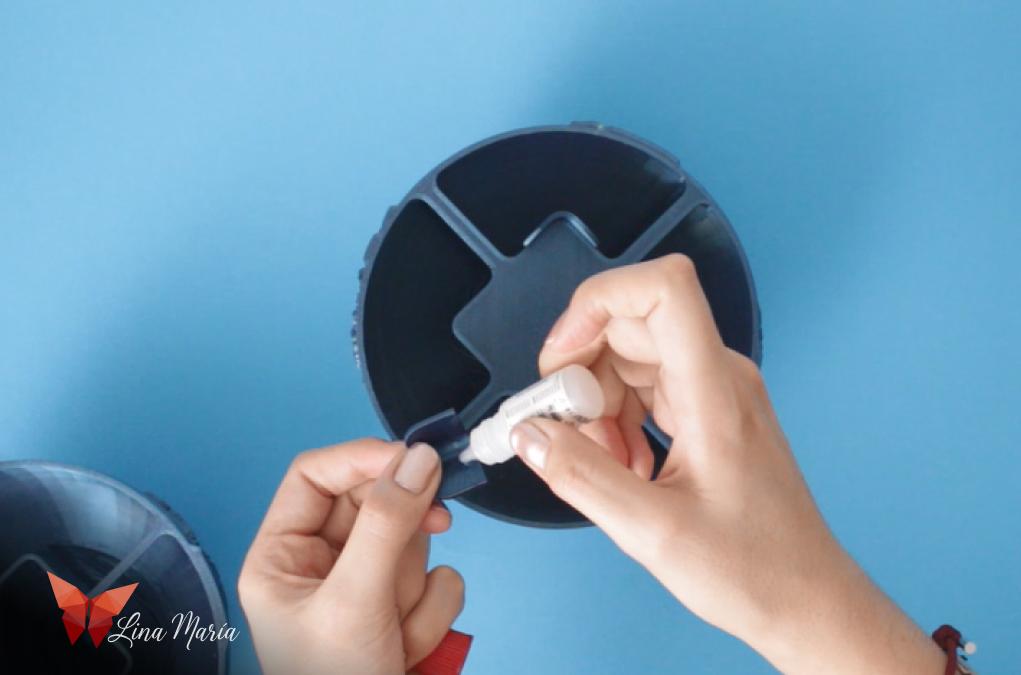

After printing the pieces, the first step was to glue the corners using nail glue.
Applying Plastic Primer

Before painting, I applied a coat of plastic primer to ensure good paint adhesion later on.
Wiring and Testing
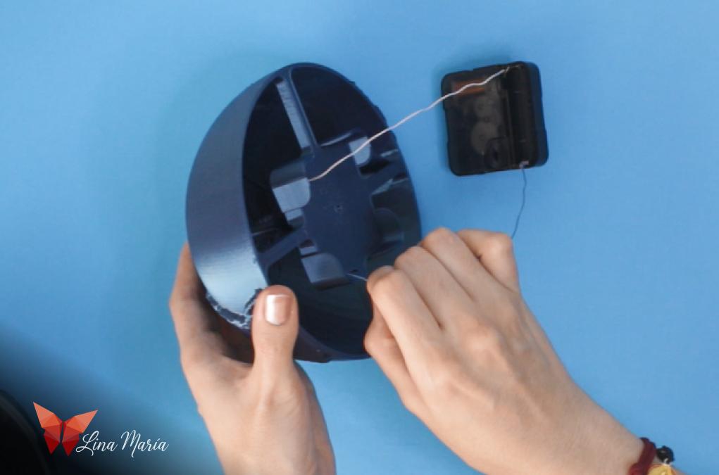

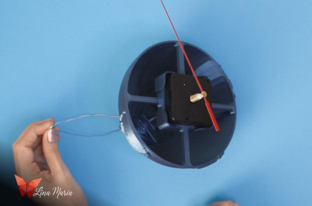
I secured the cables to the contact points of the clock mechanism and passed them through the tubes of the southern hemisphere. Then, I attached a second hand to the clock and tested it with the battery I'll use for this project to ensure everything was functioning properly.
Creating the North Axis

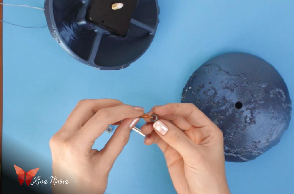
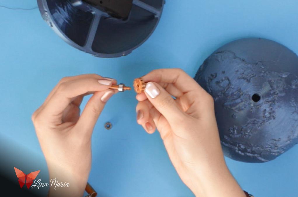


To create the north axis, I needed a tube to hold the hour section of the clock mechanism and be connected to the section that holds the vertical lines. For this purpose, I used the antenna from an old radio, which I dismantled to salvage the tubes.
To assemble the parts of the north axis, I applied some glue to "Eje1Norte", added a bearing, then applied a bit more glue to the tip to attach "Eje2Norte". Next, I inserted the tube from the radio antenna, applied a bit of glue, and additionally secured it with pliers. Finally, I placed the axis in the cavity of the northern hemisphere.
Assembling the Globe


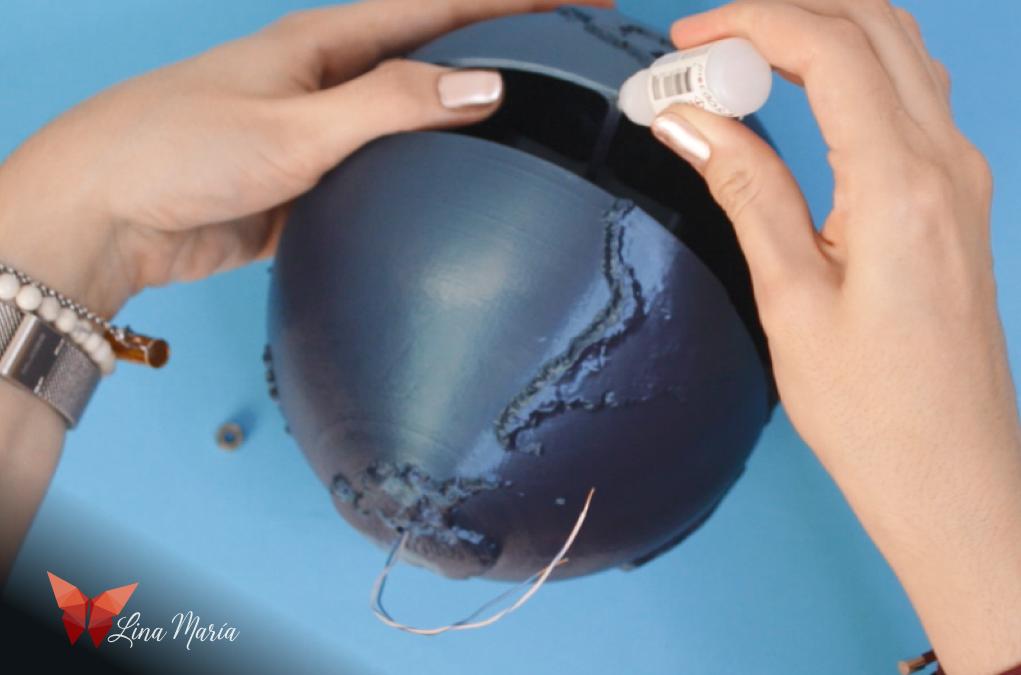

I assembled the radio antenna tube with the clock mechanism, and using the small wheel on the back of the mechanism for manual rotation, I tested that the axis rotated smoothly. Then, I applied nail glue around the edge of the two hemispheres and joined them together.
Refinement
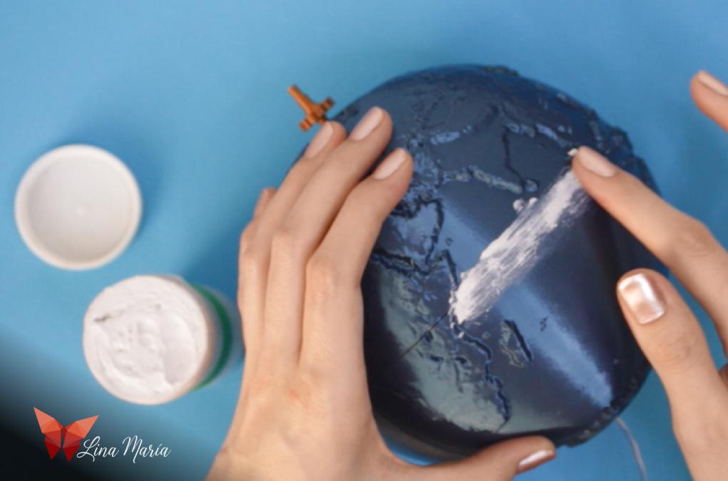

I then applied a bit of plastering compound with my finger along the seam of the two hemispheres, letting it dry overnight. The next day, I gently sanded it to reduce the line that formed at the seam between the hemispheres.
Mounting the Globe on the Base

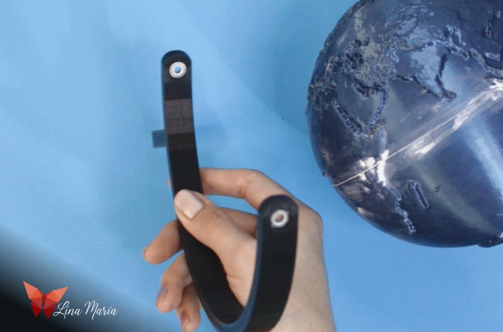
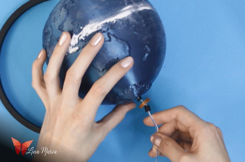

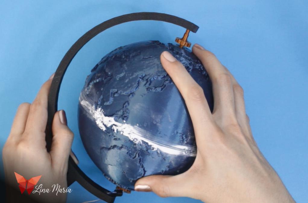
To place the globe on the base, I first installed bearings on each side of the globe support. Then, on the cables, I placed a 3mm spacer, the piece holding the vertical lines (with a bearing inside), and a 7mm spacer. Next, I threaded the cables through the bottom bearing and inserted the upper axis through the top bearing.
Creating the South Hemisphere Axis


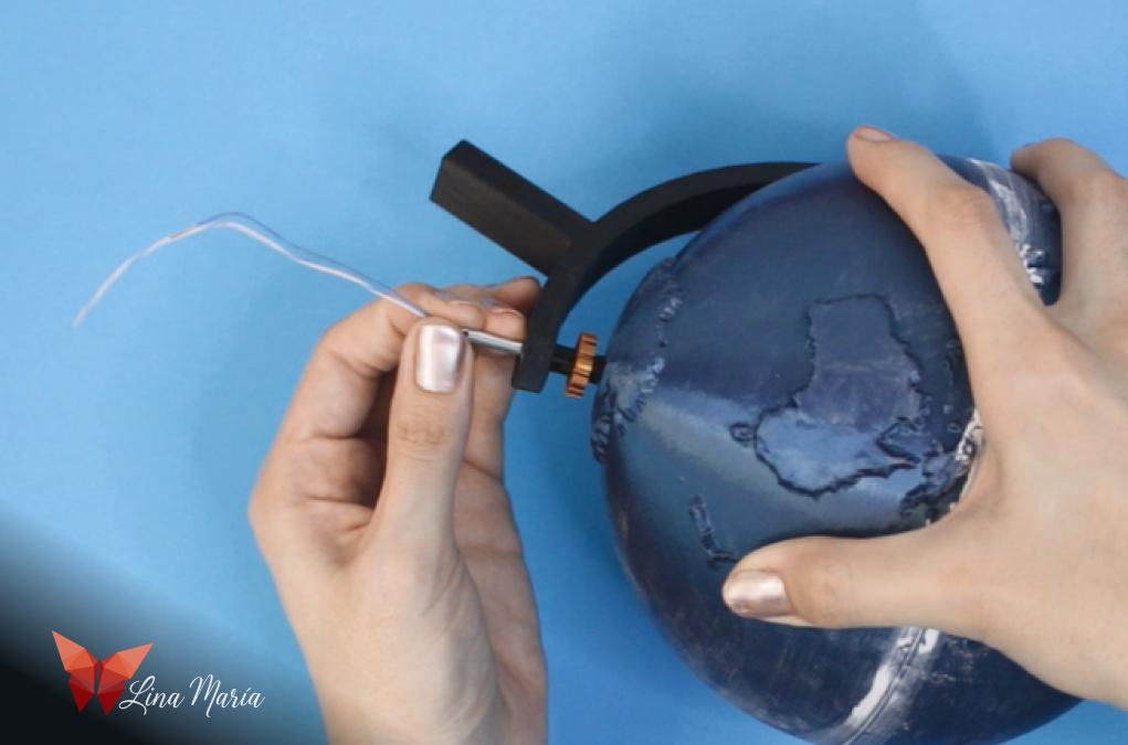
Next, I used another tube from the radio antenna to create the axis for the southern hemisphere. I applied a bit of glue to one end (the one that would be inside the globe) and inserted the clock cables into this tube. Then, piece by piece, I threaded the bottom bearing, the 7mm spacer, the next bearing, the 3mm spacer, and finally inserted the tube into the globe.
Battery Compartment


For the battery compartment, I applied a bit of glue to its hole and passed the cables and the tip of the tube serving as the axis through it. Then, I stripped one of the cables, placed a bit of copper tape at the bottom, and wrapped the cable around a stick, releasing it to form a spring in the center at the bottom.
Preparing the Second Cable and Cover
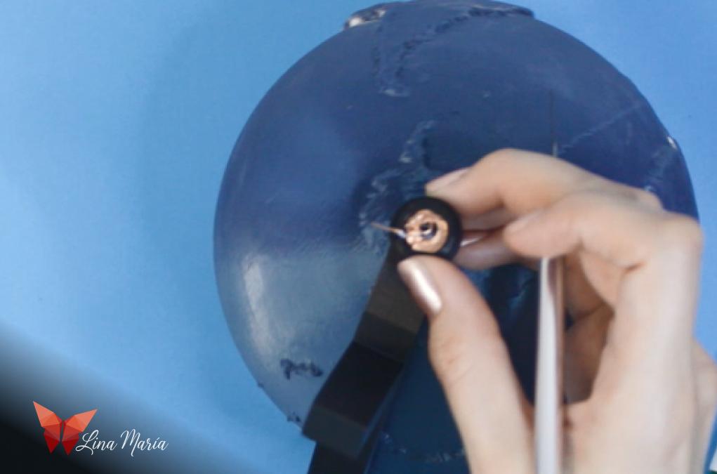


I also stripped the other cable, but this one was kept away from the center to avoid contact with the first one, and I bent it at the mark I left on the 3D print for this purpose. On the cover, I placed a circle of copper tape so that when the battery is inserted and the cover is closed, the side of the battery in contact with the cover will make a connection with the cable positioned at the edge of the compartment.
Securing the Globe Support Structure to the Base

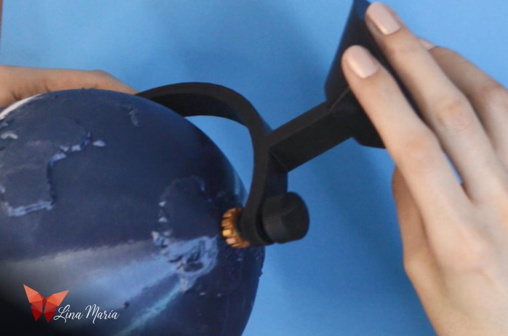
I used glue to attach the structure supporting the globe to the base.
Painting the Globe

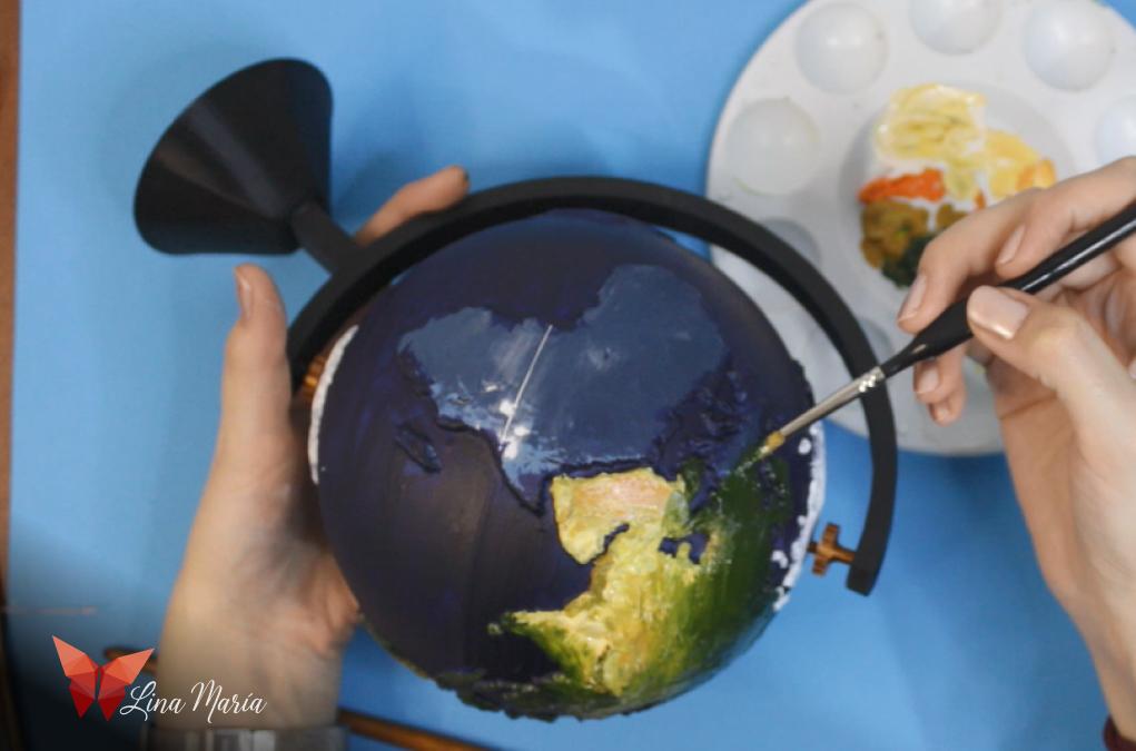
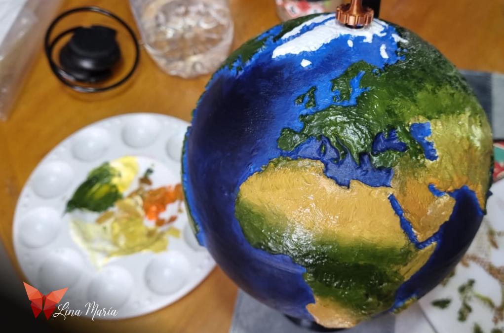
I painted the globe, referring to various satellite images of the Earth found online. To ensure a good finish, I applied two coats of paint.
Horizontal Line
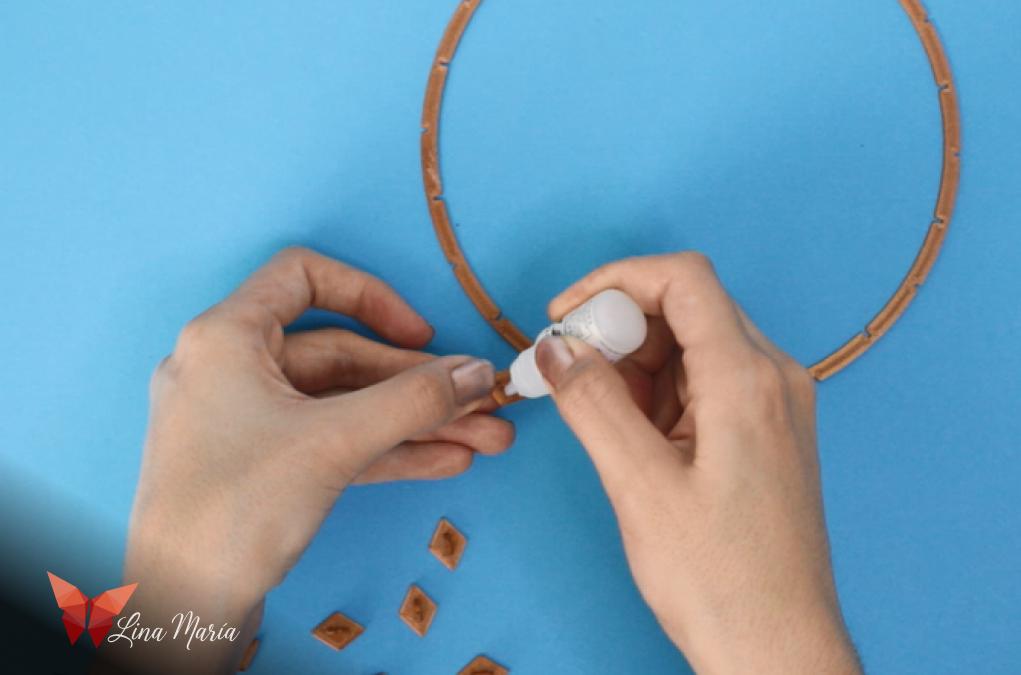
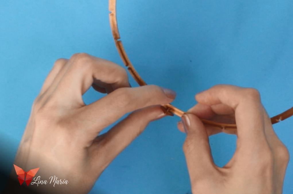
I used glue to join the pieces where the numbers will be placed to the horizontal line.
Placing the Horizontal Line and Adding Vertical Lines
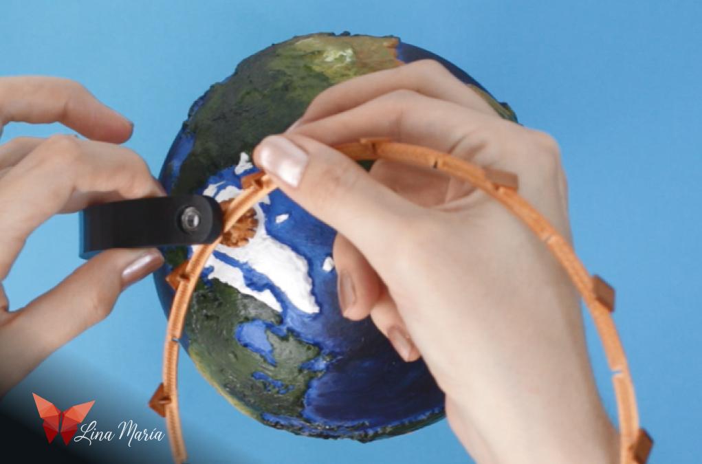
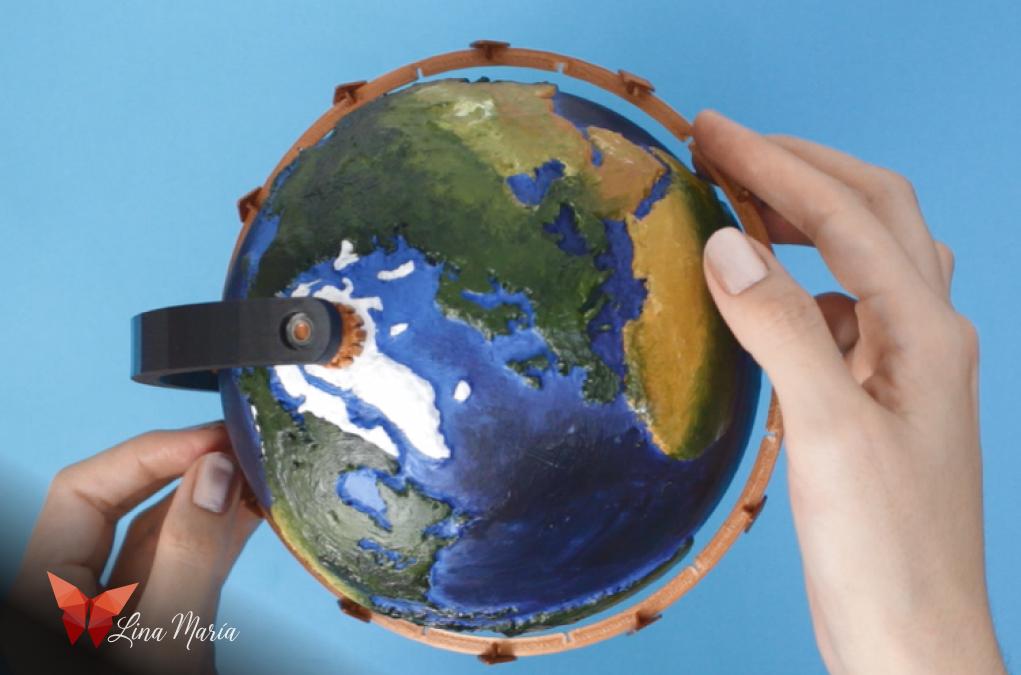

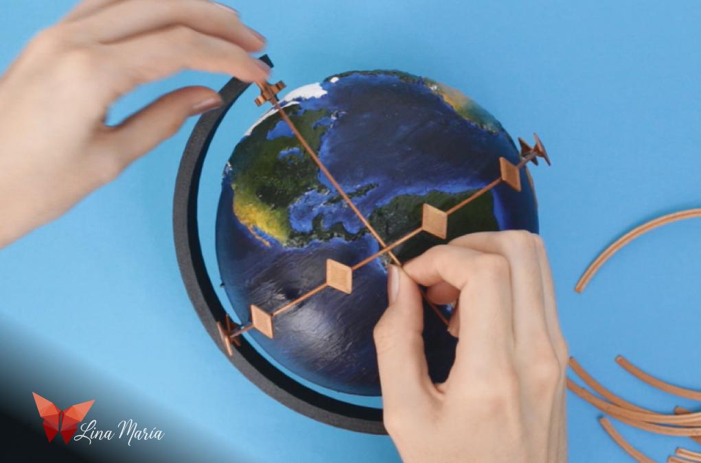
Carefully, I removed the axis of the northern hemisphere from the base to pass the horizontal line around the globe, marking the equator line, and then placed the axis back in its position. Gradually, I added the vertical lines, attaching them to the horizontal line with a bit of glue.
Attaching Vertical Lines to Bases
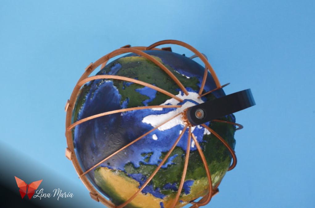
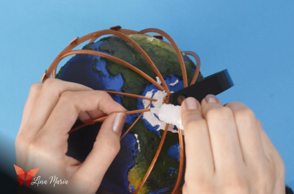


Next, I glued each of the lines to their respective bases in the north and south of the globe.
Applying Number Decals


I printed the numbers on adhesive paper, but I realized later that I had forgotten I was only going to use even numbers. (Oops! 🙈) Then, I cut them out and stuck them onto the designated sections.
Testing for Colombia
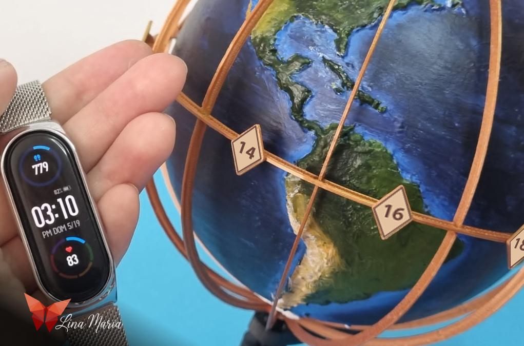

I live in Colombia, so I conducted the tests with Colombia in mind.


My best friend is currently in Moscow, so we had to test if looking at the ChronoGlobe at 3 am in Colombia would display the correct time there. And it did! It was 11 am there.