Marx Generator Circuit
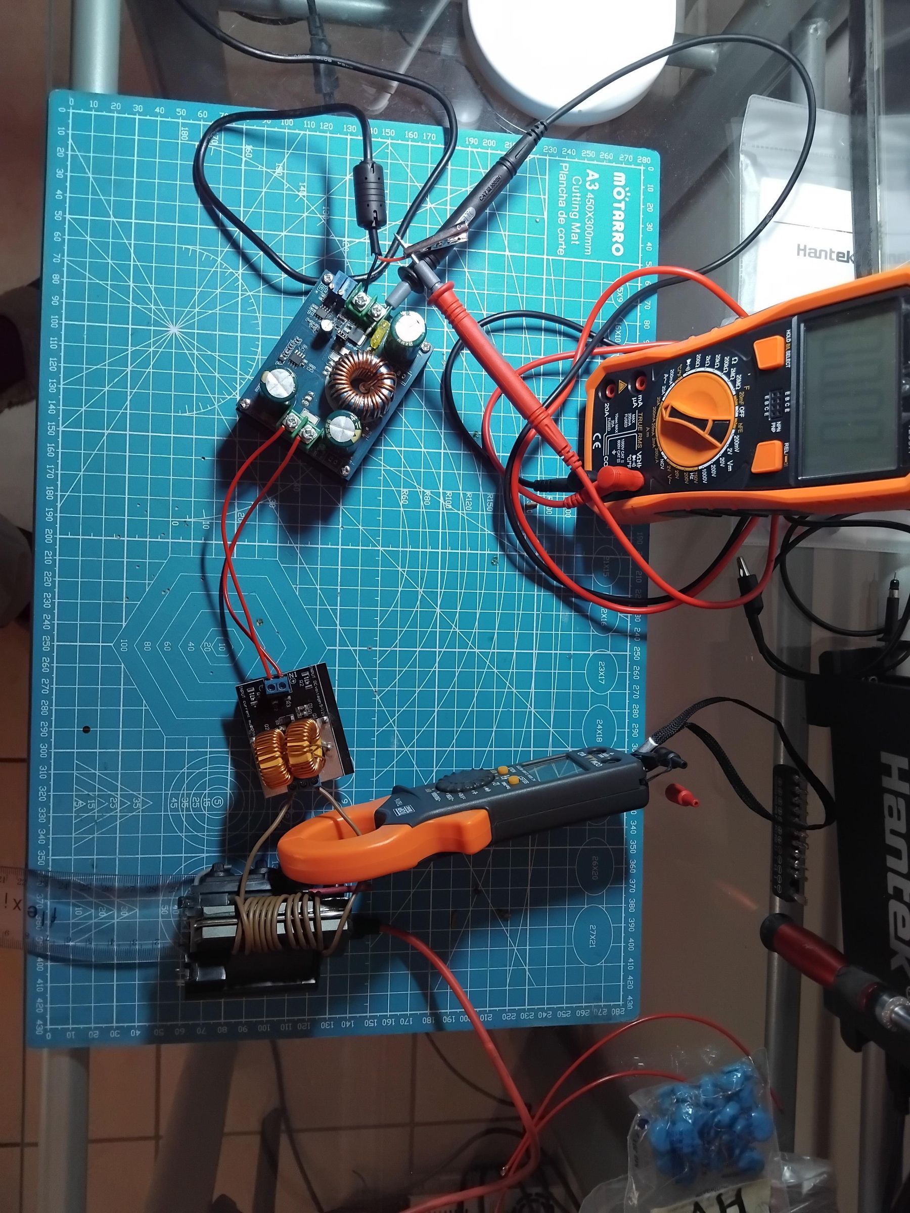
This project was my attempt at making a type of high voltage circuit know as a Marx generator. That takes a high voltage input and multiplies it to produce an even larger output voltage. The circuit is relatively simple but required a few adjustments to work with the components that I had. But ultimately it worked and produced an output voltage of 60kV !
WARNING: HIGH VOLTAGE IS DANGEROUS AND CAN KILL YOU , DO NOT ATTEMPT TO MAKE THIS IF YOU HAVE NEVER WORKED WITH HIGH VOLTAGES BEFORE!
Supplies
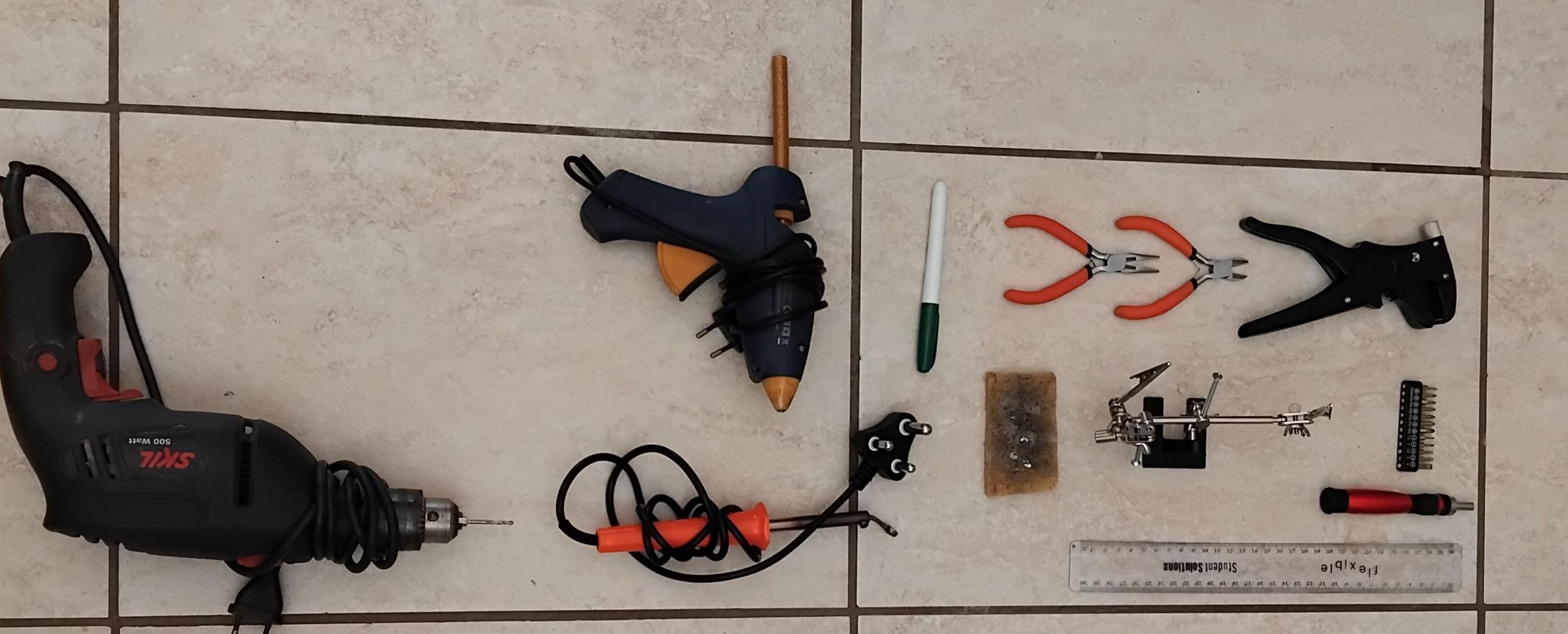
The parts needed for this circuit are as follows:
- A mini ZVS induction heater module 12V , 120W
- A BMT DC/DC 600W BOOST 12-80V 10A
- A universal laptop adapter, specifically a 100W adapter with 12V DC output (or any power supply capable of the similar ratings)
- x12 15kV , 222nF ceramic capacitors
- x16 2.2 MΩ resistors
- A flyback transformer
- x8 3X 25mm bolts
- Copper wire , 1.5 mm² (16 AWG)
- x2 Banana cables , preferably female to female
- x1 Alligator clips
The tools that you will need to build and test the circuit include:
- Solder
- A soldering iron
- Wire stripper
- Long nose plier
- Soldering helping hands
- Drill and 2.5mm drill bit
- Insulated rubber gloves
- Protective goggles
- A multi-meter and/or
- A clamp meter
- A measuring ruler
- A screw driver and set
- A hot glue gun
- Tape (any tape will do)
Setup the Power Supply
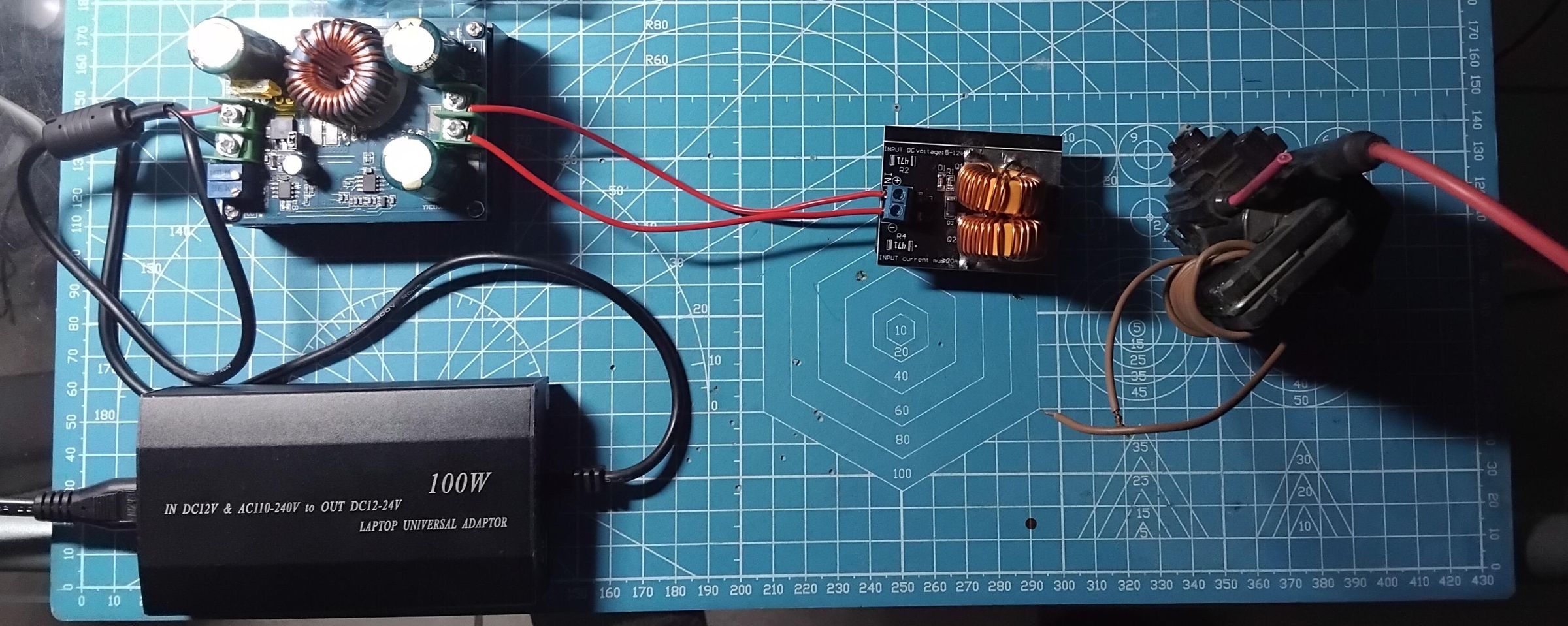
The first step is to create the right input voltage for the flyback transformer using the Laptop adapter (or an alternative power supply with similar ratings) , the boost converter and ZVS modules. Firstly use the screw driver and connect the positive and negative terminals of the power supply to that of the boost converter module , ensure as tight a hold as possible. The PSU (power supply unit) will take the mains AC power and give 12V DC that we will use as input to the boost converter. The boost converter module is not entirely necessary but I chose to include it for in case that I ever choose to scale the circuit for larger arcs and higher voltages.
Before connecting the ZVS module , we need to ensure that the output of the boost converter is at 12V DC. Plug in the supply and use the multi-meter to measure the output voltage as you turn the voltage control potentiometer. Ensure the voltage lies between 12V to 12.7V (this is the voltage I operated my circuit at).
Next we connect the output positive and negative terminals of the boost module to the ZVS module. Once complete , your power supply is complete!
Wind Primary on Flyback Transfomer
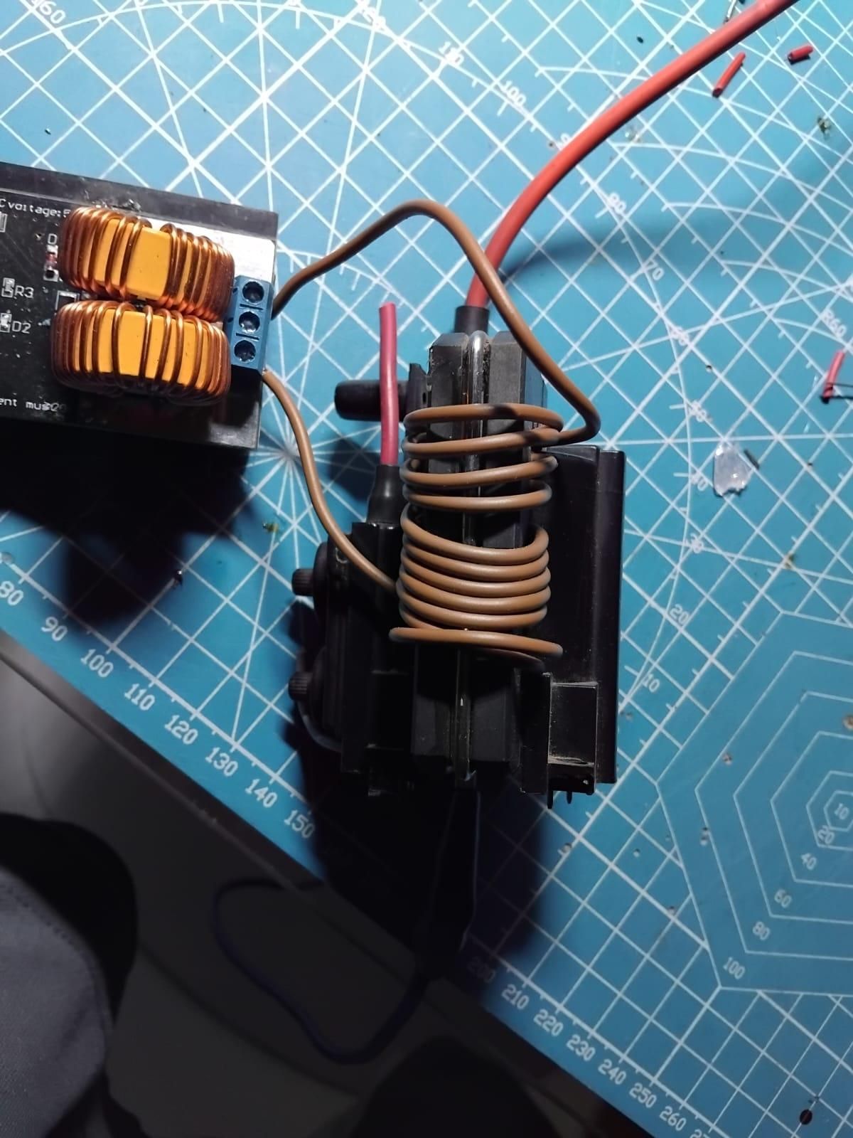
The primary of the flyback transformer is wound around the arm outside the main body of the transformer, using 11 turns of copper wire. Then connect one end of the primary to the left most output terminal of the ZVS module and the second end to the right most output terminal . There is no need to use the middle output terminal on the ZVS module!
Creating the Marx Circuit
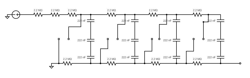
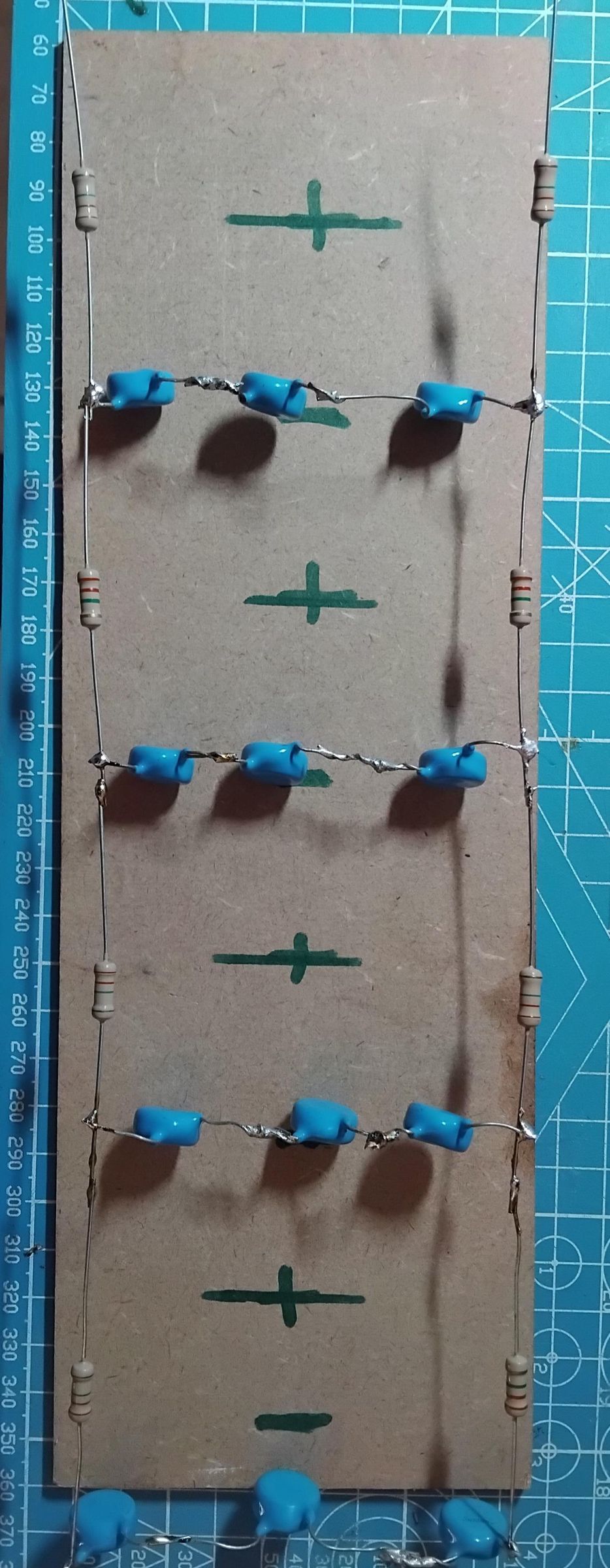
To create the Marx circuit, we need to solder 4 banks of , 3 15kV 222nF capacitors in series in order to hold the full 30kV output voltage of the flyback transformer. To connect the banks together we'll use the 2.2MΩ resistors and solder the banks in parallel.
Prepare the Wood Base
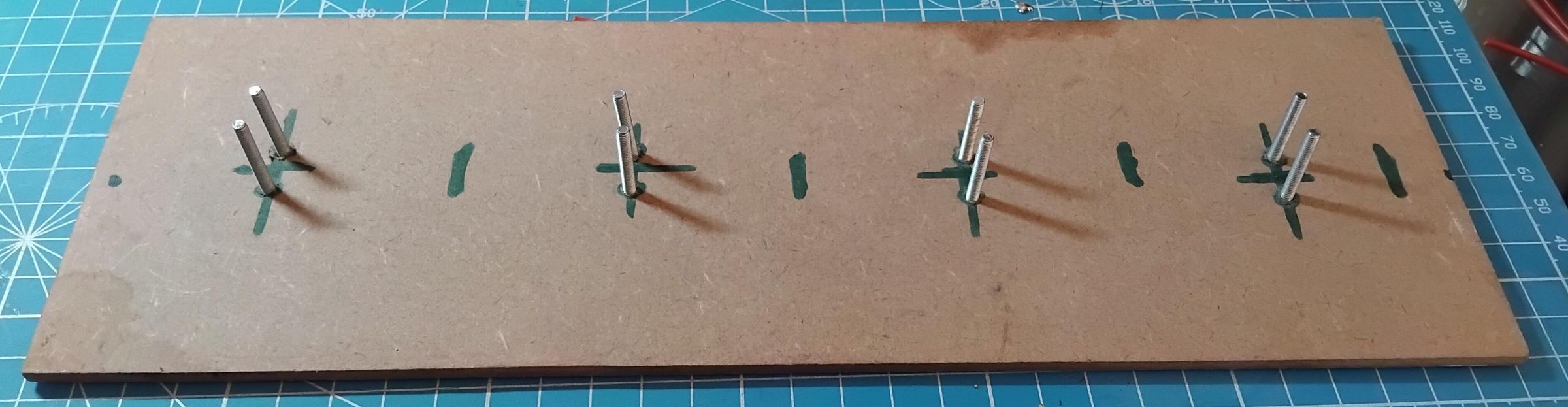
The spark gaps will be made up of 25mm bolts screwed into the wooden base , approximately 1cm apart , but in retrospective , a more suitable distance would be just under 1cm to ensure consistent discharge once the capacitors are fully charged.
Drill 8 , 3mm holes into the wood , in the form of 4 sets of 2 holes parallel to each other at equal distances. Pass the bolts through the holes and place the Marx circuit over it so that the bolts are in the centre of each block.
Complete the Circuit
.png)
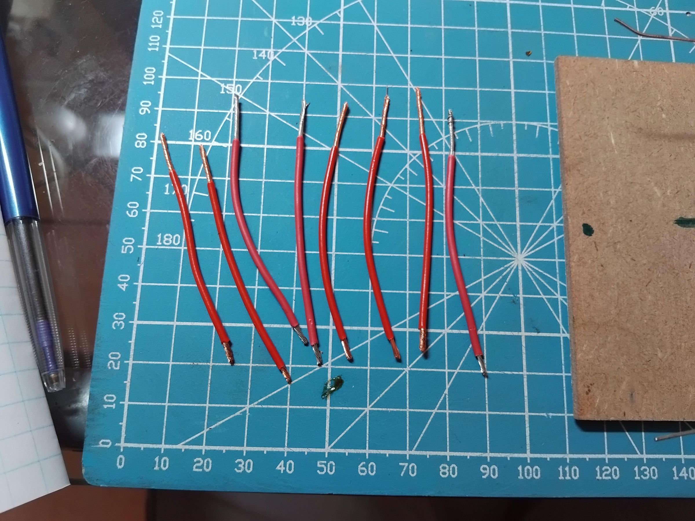
Cut the copper wire into 8 pieces of suitable lengths and use the wire stripper to remove the insulation , removing more on one side than the other. These wires will serve as electrical connections to the spark gaps. Solder the copper wires to the corners of the Marx circuit and use nuts to secure the copper to the 25mm bolts.
Use the banana cables and alligator clip and connect the flyback output negative terminal to the Marx circuit ground , and the flyback high voltage terminal to the positive terminal of the circuit. One more cable should be used to connect to ground and move the second end to the output of the circuit but Do not connect it physically to the output!! It should be at a distance of about 2cm to 3cm.
Safety Precautions
Before the circuit is powered, there are certain safety precautions that need to be followed to ensure that we don't get shocked or worse!
- Wear protective gloves and goggles when working with the live circuit at all times.
- Only use one hand when making changes to the circuit.
- Always turn the supply off before making changes to the circuit .
- if the supply is live , use the long nose plier to handle any high voltage cables or conductors , do not use your hands directly!
- Once the supply is off, use the screw driver to discharge the capacitors by shorting the spark gaps at every stage.
Power the Circuit
Turn on the power supply and you should immediately see arcing on the spark gaps followed by a larger arc on the Marx output to ground , this should occur every second or so. Once you turn the supply is off , ensure you use the screw driver and insulated glove to discharge the capacitors.
Measurements
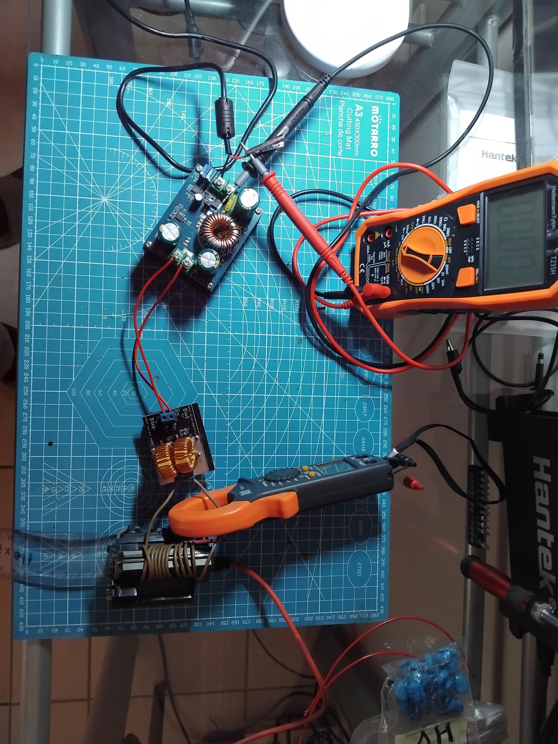
To measure the high voltage output , will use the breakdown voltage of air along with our ruler:
- Ensure the supply is off and place a ruler from the output of the Marx circuit to the the circuit ground cable and measure the distance.(Place the ground cable and circuit output in line with one another)
- Turn the supply on and if arcing occurs, record the distance, turn the supply off and increase the distance by 1cm.
- Repeat the process until the output is no longer able to arc .
- To find the output voltage we'll use the following formula: V_out = V_air x distance
- Where V_air is the breakdown voltage of air , given as 30kV/cm and distance is the horizontal distance between the circuit output and the ground cable, on the last time the circuit arced.
My circuit produced an arc until about 2cm resulting in an output voltage of 60kV. For a 4 stage Marx with an input voltage of 30kV , we should expect 120kV. But I believe that this is due to the fact that the capacitors do not discharge simultaneously. Thus reducing the output voltage.