Maurice - a Compact ORTF3D Immersive Microphone
by DJJules in Circuits > Audio
15281 Views, 79 Favorites, 0 Comments
Maurice - a Compact ORTF3D Immersive Microphone


My recent passion, or one might call it – addiction – is immersive audio. What stereo did to mono decades ago, immersive audio is doing to stereo. It started when I attended an Audio Engineering Society (AES) convention in 2023. That was where I first heard Dolby Atmos played on a 7.1.4 system. I was hooked. I built my own 7.1.4 playback system featured here. I am also a microphone builder as many of you already know. I have had the thrill of listening to some truly stellar recordings that were made with 10’s of thousands of dollars in microphones. Along with multiple microphones, you also need multiple microphone stands, lots of cabling and, multichannel recording. Fortunately multichannel recording has come down in price but even some of the microphone stands required to do this conventionally are quite pricey. I wanted to build a compact array that solved a few problems. It should be easy to set up by a single person, inexpensive, compact visually, and of course, sound good. After a couple iterations, I came up with what I am calling Maurice. Maurice is a “Symmetrical ORTF3D” microphone array. Maurice is also a variant of the “IRT Cross”.
Supplies
A complete kit of all the parts EXCEPT the furry wind protection dead cats can be found here:
https://www.jlielectronics.com/diy-microphone-kits/maurice-ortf-kit/
Mounting parts:
https://www.amazon.com/Longdex-Tripod-Barrel-Connection-Articulating/dp/B07WXGYH1G/
https://www.amazon.com/HJ-Garden-Stainless-Monopod-Mounting/dp/B081Q3T65Y/?th=1
https://www.amazon.com/Anwenk-Anti-Scratch-Accessories-Protection-Anti-Slippery/dp/B07R44FP5C/?th=1
https://www.amazon.com/Release-Adapter-Thumbscrew-Mounting-Frgyee/dp/B096FG59D2/
Light stand: https://www.amazon.com/dp/B0DQNL7GVX?th=1
Dead Cat (8) https://www.aliexpress.us/item/3256805353286850.html
E6000 Glue
https://www.amazon.com/E6000%C2%AE-Hi-Visc-3-7-Ounce-Adhesive/dp/B0044SB3M8?th=1
What Is Immersive Audio?


What is immersive audio? That is a great question. The best definition I have so far is this: “Immersive audio is a method of sound reproduction that creates the perception of sound coming from all around the listener—including from above and below—resulting in a three-dimensional auditory experience.” In simple terms, we need extra speakers; speakers above and behind you. How many is a separate subject, but in my opinion, and the setup that I have, is 7.1.4. So, what do all those numbers mean? They are the number of speakers and where they are. In this case the “7” is seven speakers at ear level, “1” is one Low Frequency Extension (LFE) or subwoofer, and the “4” is four height speakers. Original surround sound is 5.1. Five ear level speakers and one subwoofer. Stereo is 2.0 but no one really calls it that. Although you will see 2.1 systems, meaning they are stereo with a subwoofer. Technically the microphone we are building is 4.0.4. Each element in the array maps directly to a speaker. This is what separates Maurice from Ambisonic microphones.
The Design
Maurice has eight cardioid capsules (these), set up in four pairs. Each pair is a stereo ORTF setup. Meaning there are two cardioid microphones spaced 17 cm apart, each facing outward 55° This technique was invented in 1960 and is still in use today. It works as it provides two things well. First is level differences between the two channels. Second and more critically, timing differences. 17 cm is equivalent to about .5msec of delay. It isn't a lot, but adds spaciousness and makes the sound recorded at both capsules non-coincident. Since we want to capture height information, we rotate each ORTF pair 90° so they are vertical. Then we face two pairs forward 17 cm apart at +/-45°. Then two pairs face to the rear in a mirror image. The four pairs form a cross, all 90° apart. Interestingly there is a microphone technique called the IRT (Institut für Rundfunktechnik) cross. That increases the spacing to 20-25cm and only uses four microphones. This is used a lot to record ambience for surround sound. If you think about the angles we are using, by angling the up and down 55° vs the left/right and front/back at 45° we are actually prioritizing height information over normal stereo spread.
There are two parts to the build. The microphones and the array itself. The array is 3D printed with a few extra parts to allow it to mount to a tripod or light stand.
The Microphones
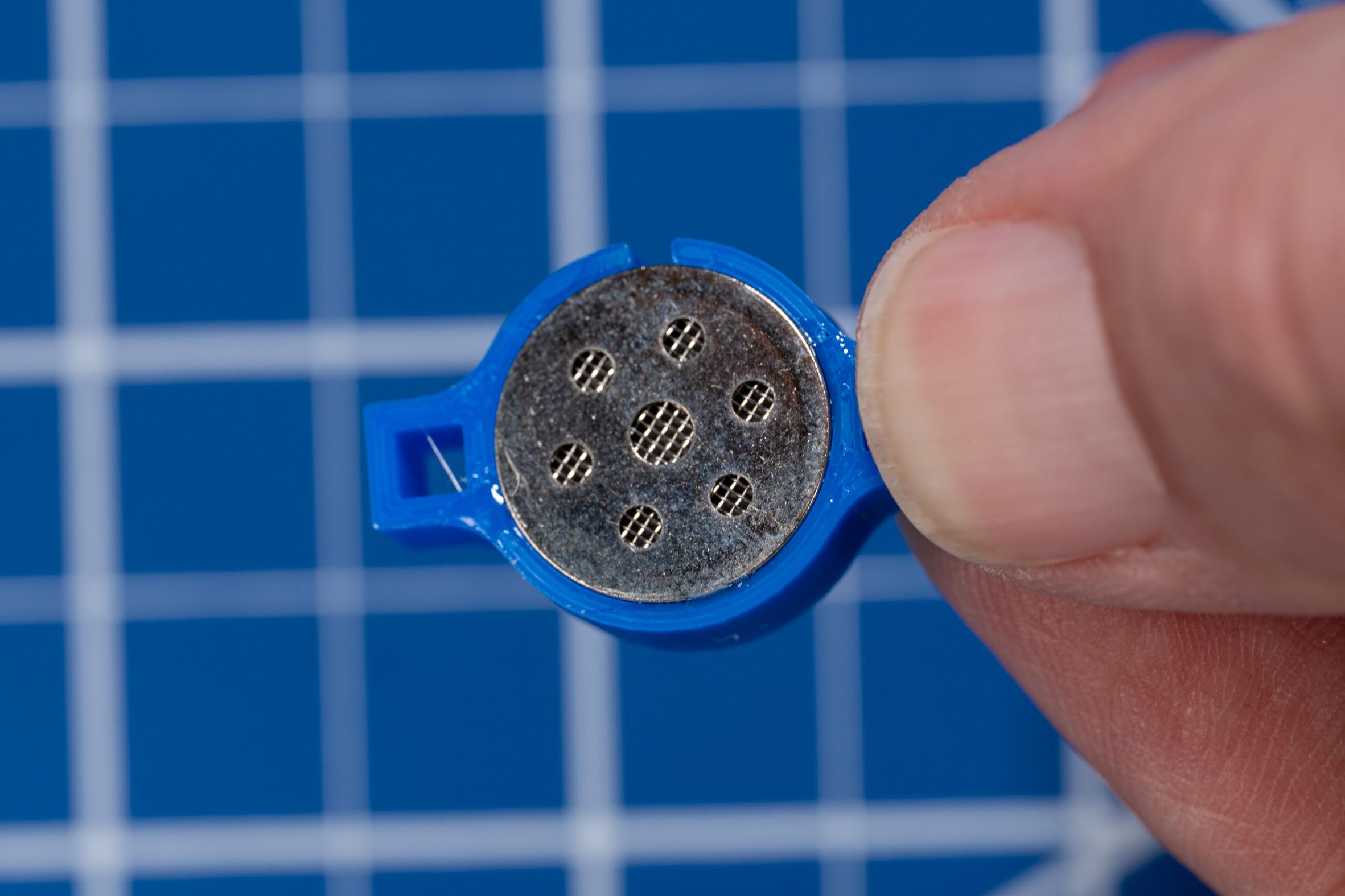


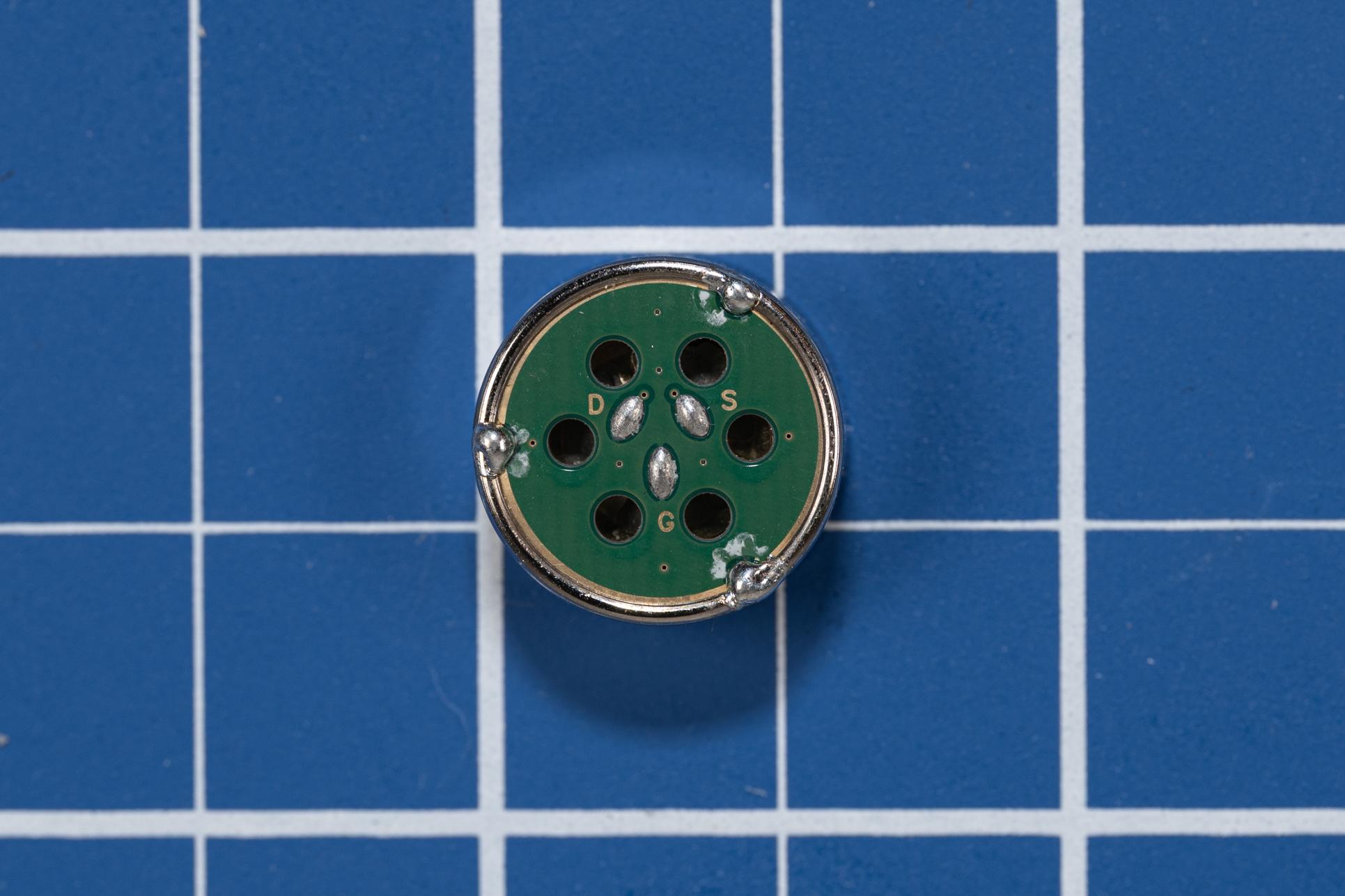
The microphone capsules we are using are JLI 16mm electret condensers with a built in FET. It is a cardioid capsule that is also called a “Three Wire” capsule. Instead of two leads, labeled “+” and “Ground”, it has three. They are “S”, “D” and “G”. Which stands for Source, Drain and Ground. A normal or “Two Wire” electret capsule internally has its source tied to ground. We are going to do that externally. Then we are using the SimpleP48 circuit just like the AmbiAlice, my first order ambisonic mic. This makes construction simple and produces an excellent microphone. The capsule has smooth frequency response and a very respectable self noise figure. Date sheet here.
Three Wire to Two Wire:

We are going to connect the Source to Ground externally.
The Simple P48
This circuit belies its simplicity. The key is how it interacts with the microphone preamp and the two 6.8K resistors that supply the 48 Volts. They become integral to the overall circuit. So here is how this works: The “+” terminal or Drain of the FET connects to Pin-3 of the XLR jack which is supplied by 48V through a 6.8K resistor. The Source of the FET connects to the 100K resistor and then to Ground. The 100K forms a voltage divider with the FET. The FET self biases due its design that includes a leakage diode between the Gate and the Source. The Gate is internally connected to the Capsule diaphragm. This is an Electret capsule, meaning that it is internally polarized. When a positive pressure is applied to the microphone, its internal diaphragm moves closer to a backplate. Because of the fixed charge, a positive going voltage is applied to the gate of the internal FET. That causes it to conduct more, lowering the voltage across the FET. The end result is that the voltage on Pin-3 of the XLR goes down. Simultaneously the voltage on the Source goes up, which is coupled across the 3.3uF capacitor into Pin-2 of the XLR. This gives us a balanced signal into the mic preamplifier. All with two external components. The one catch with using the Simple P48 is that the case of the capsule is floating at a voltage above ground. It can't connect to ground or the circuit won't work. The capsule needs to be insulated. That is not a problem as we are 3D printing capsule holders along with the rest of the array. Bear that in mind while testing them.

How it looks when wired to an XLR connector:

There are a couple nuances to keep in mind: First is that we are connecting the Drain which is “+” to Pin 3. That is correct as incoming sound pressure causes the voltage to go down (less positive) as the FET conducts more. That conduction also causes the voltage on the combined Source/Ground connection to go up (more positive). That is exactly what we want in a balanced audio signal. Second is that the shield of the Mogami cable is connected to ground at the XLR and not connected at the mic capsule end. This provides us with our RF/EMI shielding. The capsule also contains two EMI caps that really help with Cell Phone and WiFi interference.
The Microphone Build

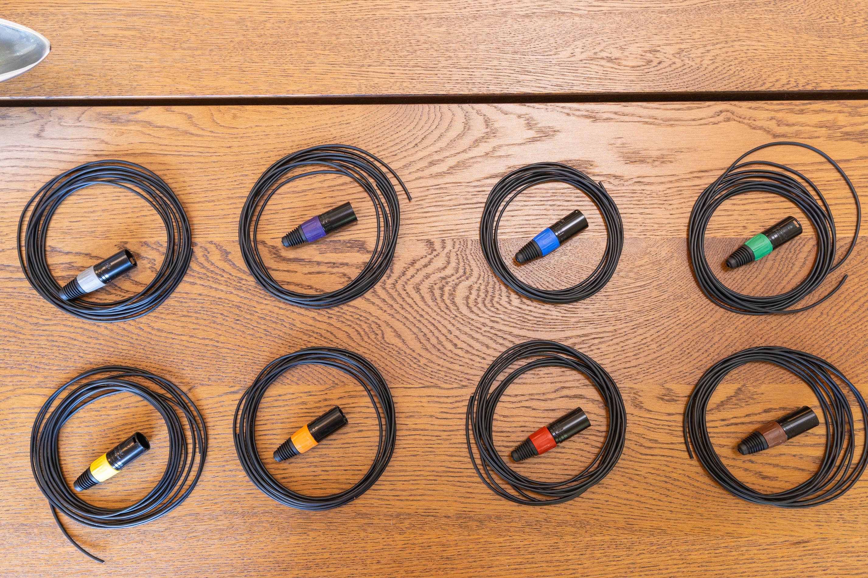
For Maurice to work properly, we need to keep track of the capsules, microphone inputs, and recorder channels. The solution is to color code the XLR connectors. We are using resistor color codes. Each mic element uses 12 Ft of Mogami W2697. This is thin 2 conductor shielded microphone cable.
The Mic Build
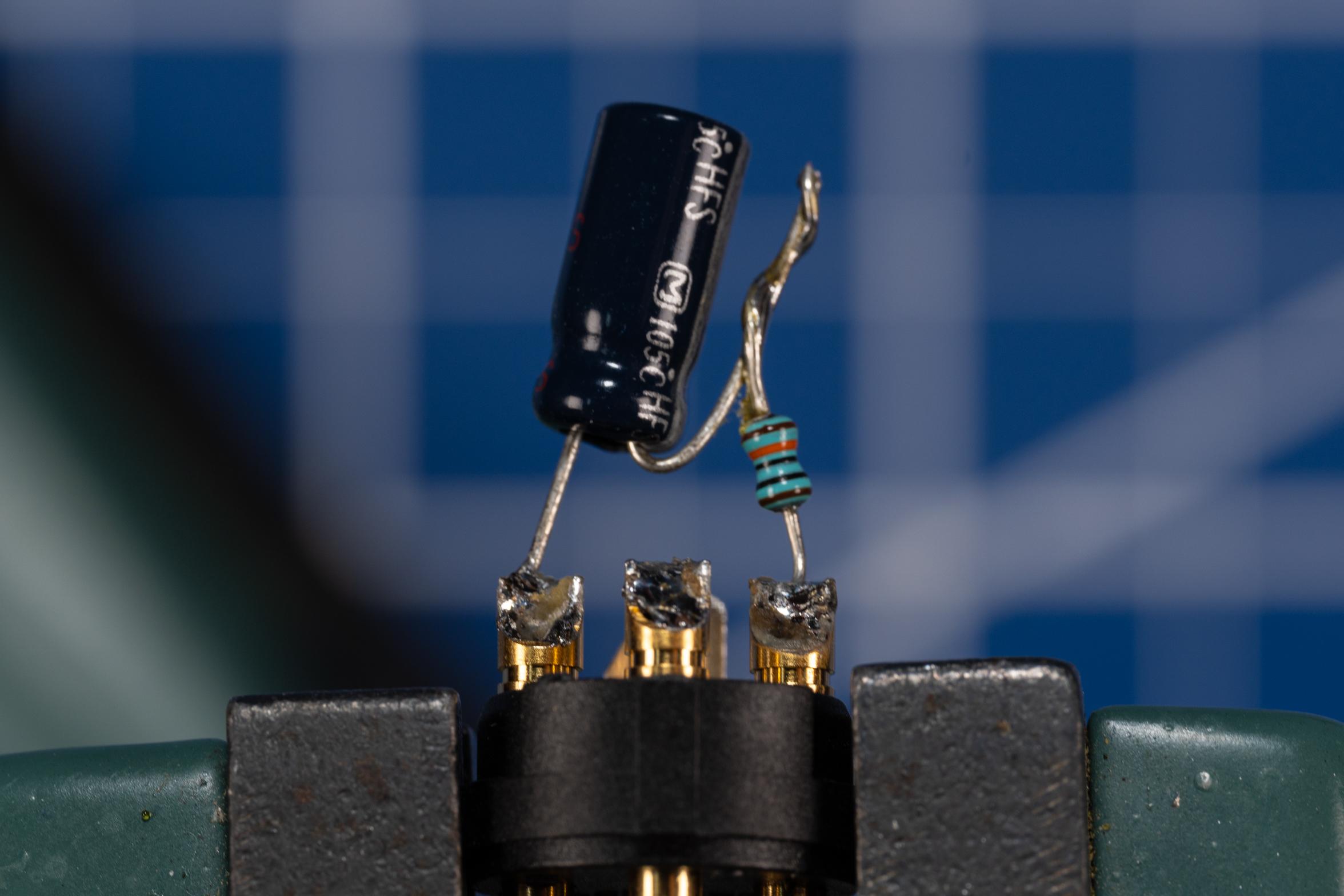
- Prep the XLR end by tinning the cups for Pins 1, 2, and 3.
- Fold the negative lead of the capacitor up towards the body.

- Twist it with one side of the 100K resistor.
- Solder the connection and trim to the same length as the capacitor.
- Trim the leads on the capacitor and resistor to about ¼” below the capacitor.
- Solder the resistor to Pin 1.
- Solder the capacitor to Pin 2.
- Slide the XLR boot onto the cable (so you don't have to slide it over all 12Ft later…) We are using 8 different colors corresponding to resistor color codes 1-8.

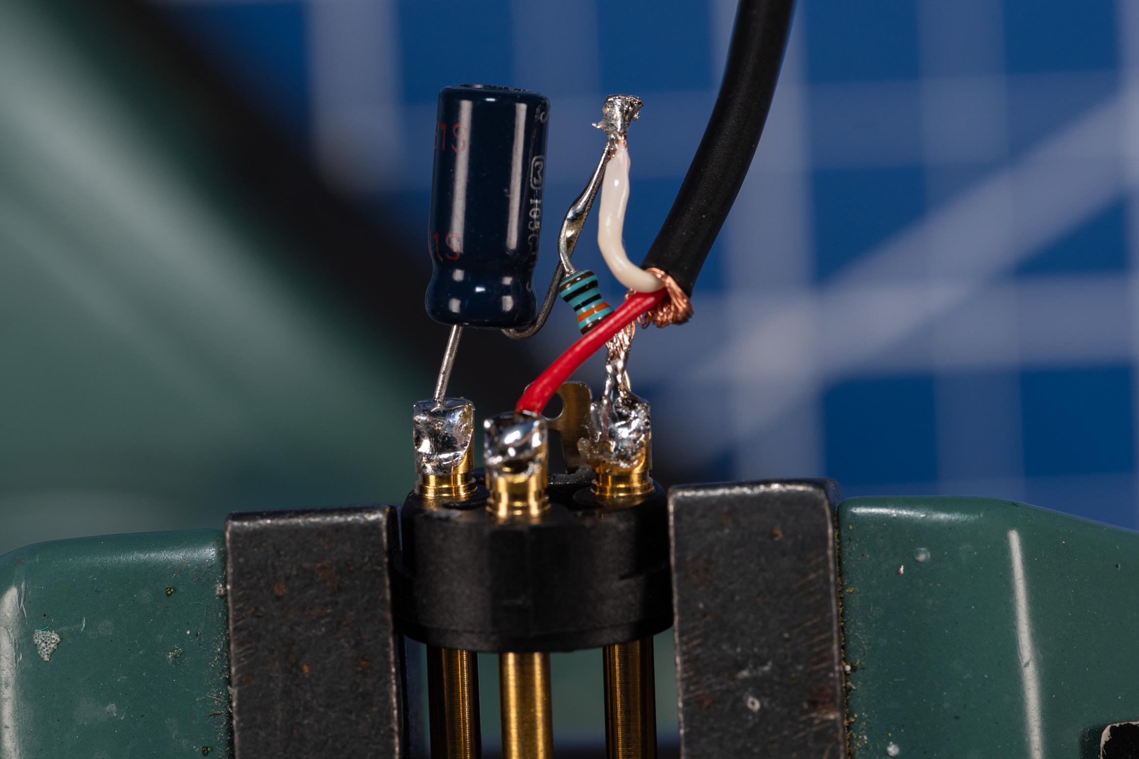
- Prep the XLR end of the cable:
- Strip back about ½” of the outer sleeve.
- Twist the shield together and move over to one side.
- Tin the end of the shield.
- Strip a small amount of the red and white insulation.
- Tin both of these.
- Connect the wires as follows:
- Shield to Pin 1.
- Red to Pin 3.
- White to the junction of the 100K resistor and 3.3uF capacitor.

- Inspect your work and then assemble the XLR end.
- Glue the 8 capsules to the capsule holders with a small amount of E6000. Let this dry for 4-6 hours before proceeding.

- Prep the other end of the Mogami wire for connection to the mic capsule.
- Strip back about ¾” of outer sleeving.
- Twist the shield and pull back to one side.
- Carefully cut the shield off as close to the insulation sleeve as possible. We don't want any stray strands touching anything.
- Strip back all but ⅛” or so of the insulation from the white inner wire.
- Twist that and tin it.
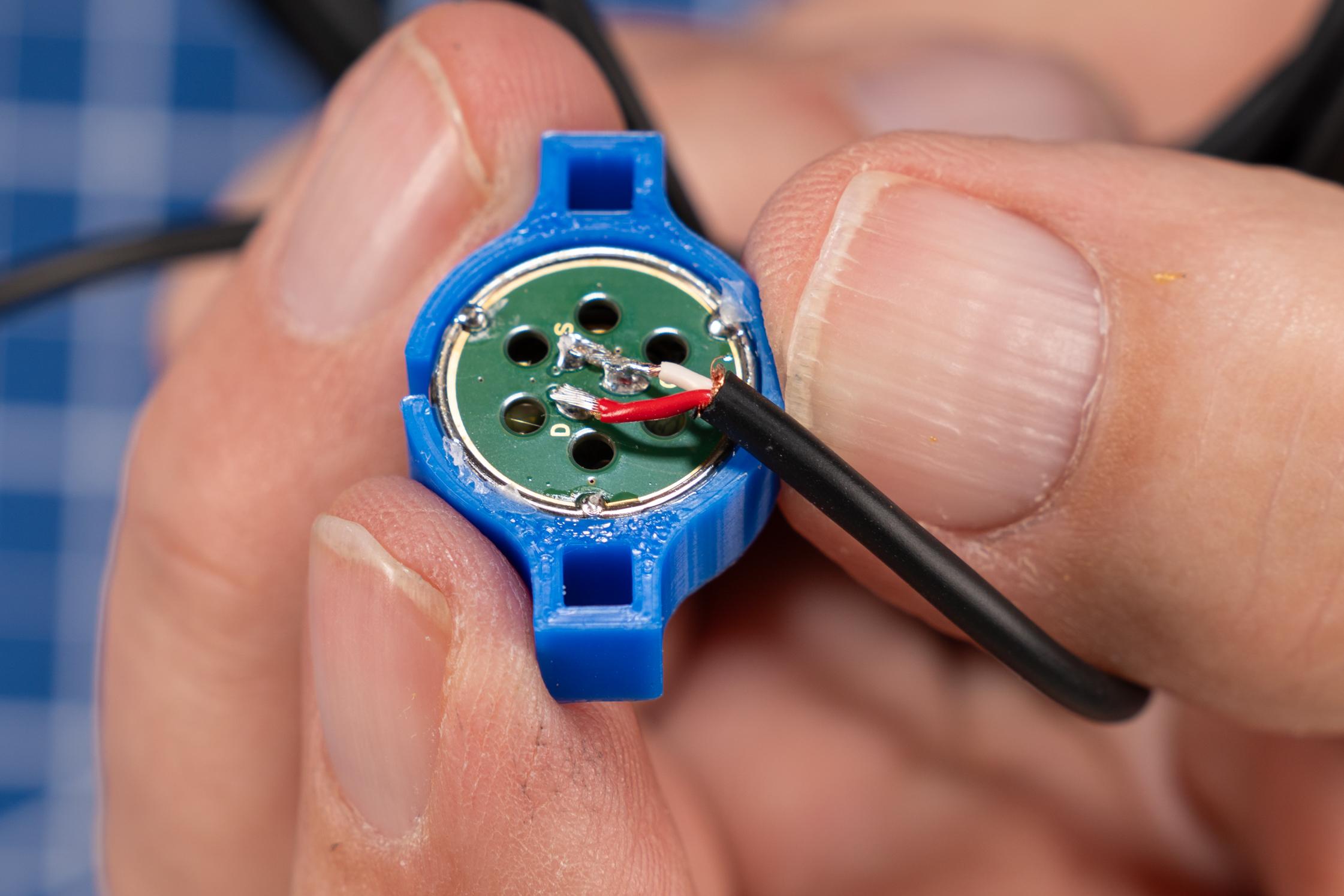
- Place the capsule in a hobby vice or other method for holding it in place.
- Cut the tinned white wire long enough to connect the “S” and the “G” pads
- Cut the red wire long enough to reach the “D” pad strip about ⅛” inch of insulation and tin the exposed wire.
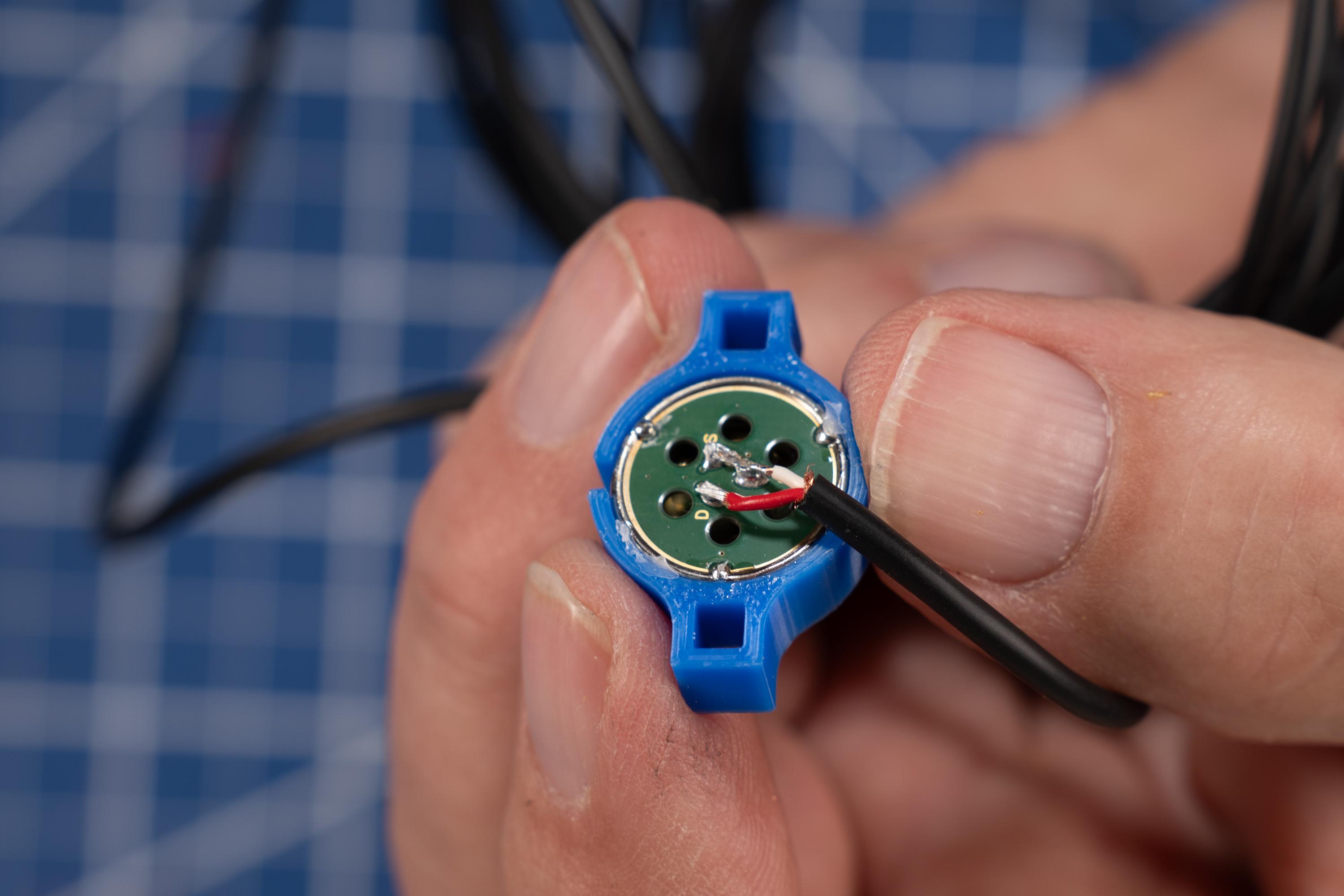
- Clean the soldering iron tip and apply a small amount of solder then connect the “S” and the “G” pads with the white wire.
- Solder the red wire to the “D” pad on the mic capsule

- Inspect your work and test the mic by connecting it to a preamp and ensuring it works. Be careful not to touch the case of the capsule.
- Repeat for remaining mic capsules.
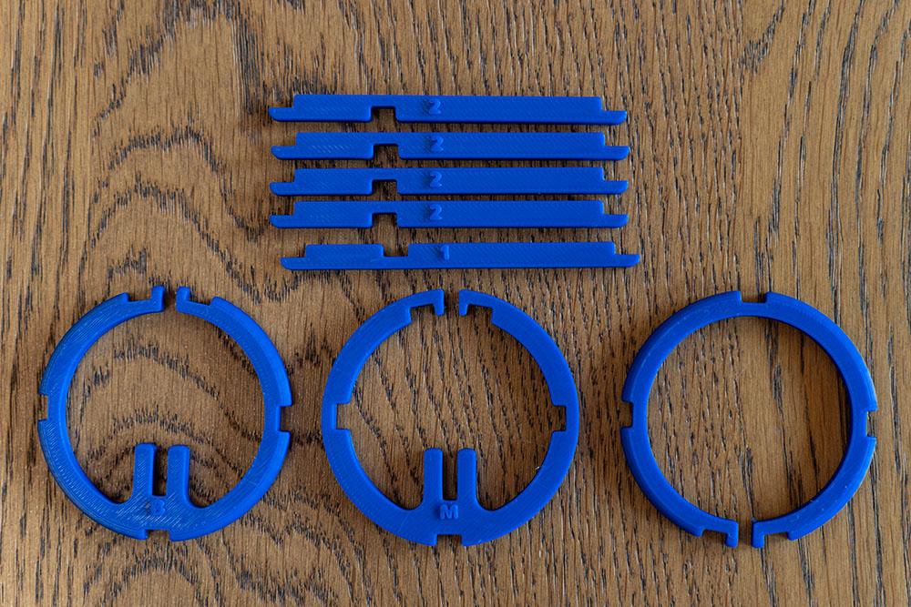
The Array Assembly
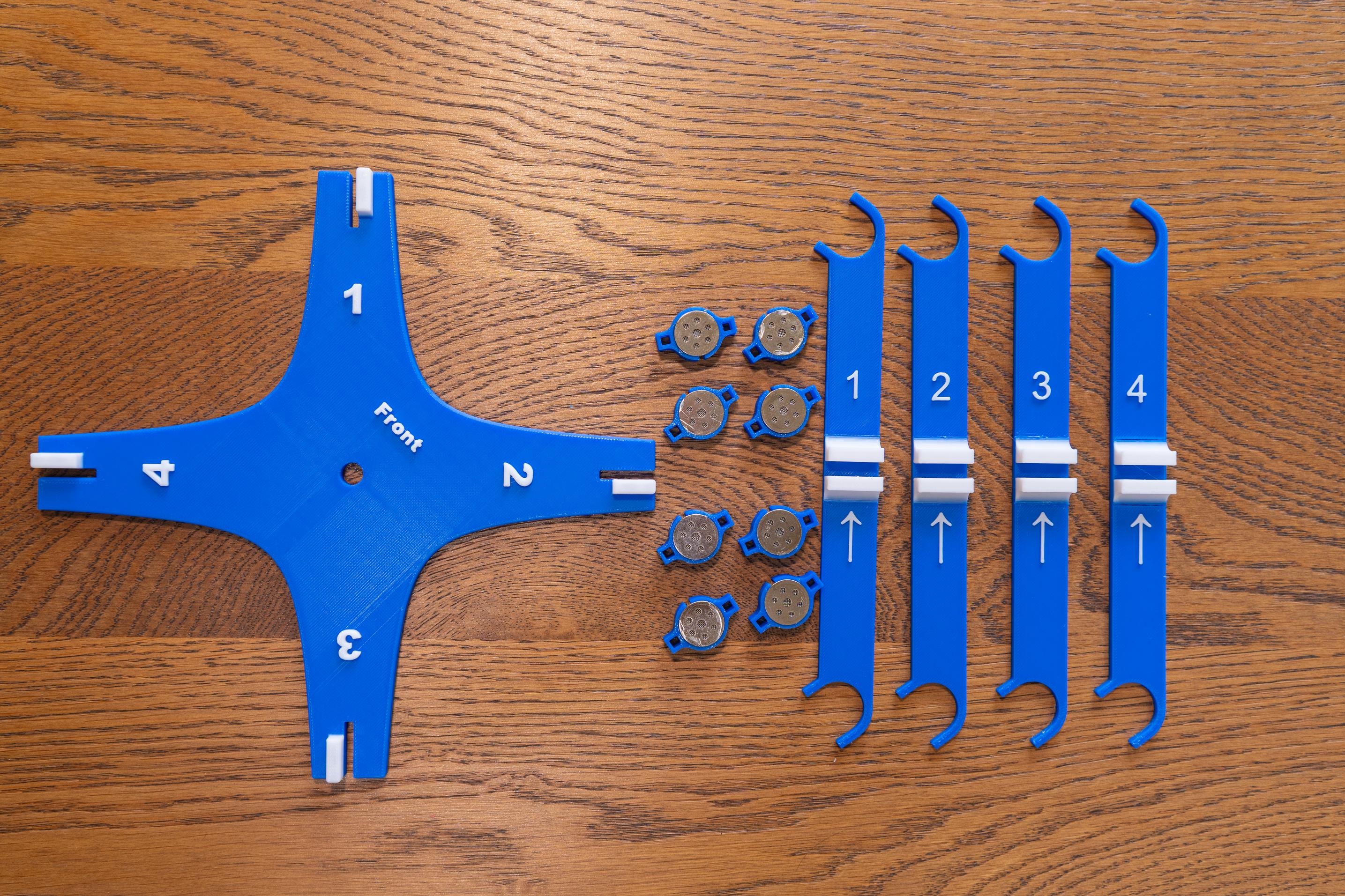


The parts for the rest of the build are all 3D printed except for a few mounting pieces that allow it to attach to a light stand. The files for this are provided in both .stl format and .3mf. For those with a Bambu labs 3D printer, the .3mf files use two colors where appropriate to enable easy identification of the directions and mic elements. There is one .3mf file that has 9 capsule holders and 9 wire clips. This gives you a spare for each.
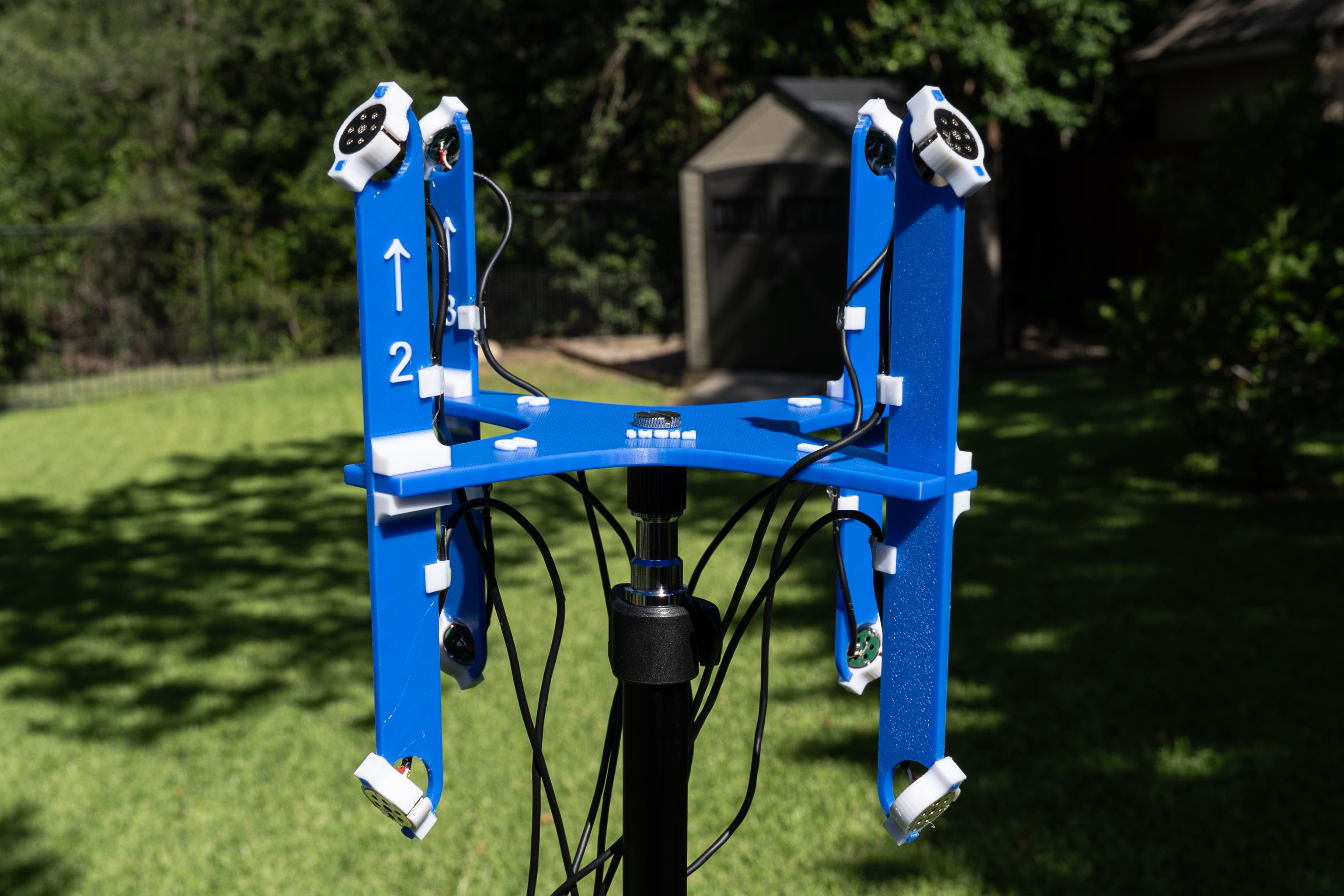
Each part went through multiple revisions to get to the final design. My design goals were three fold. First, to place each capsule in the correct orientation to achieve the spacing and angles I wanted. Second, to make it easy to build, and finally third, to make it easy to set up and use. I feel confident I have done so. Here are the parts:
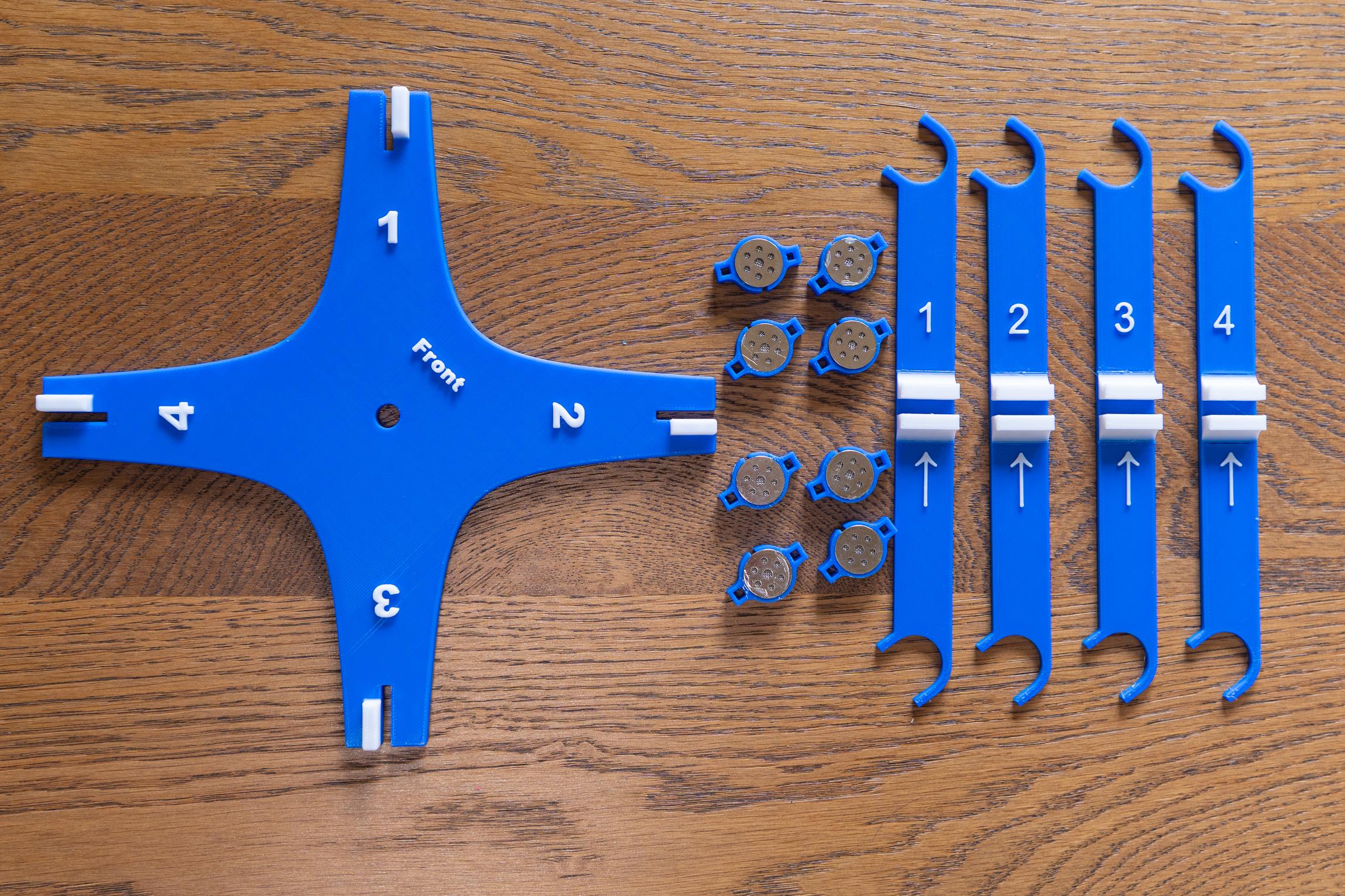
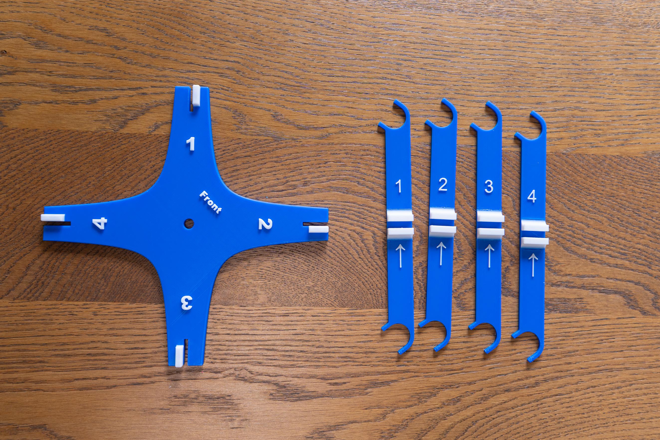
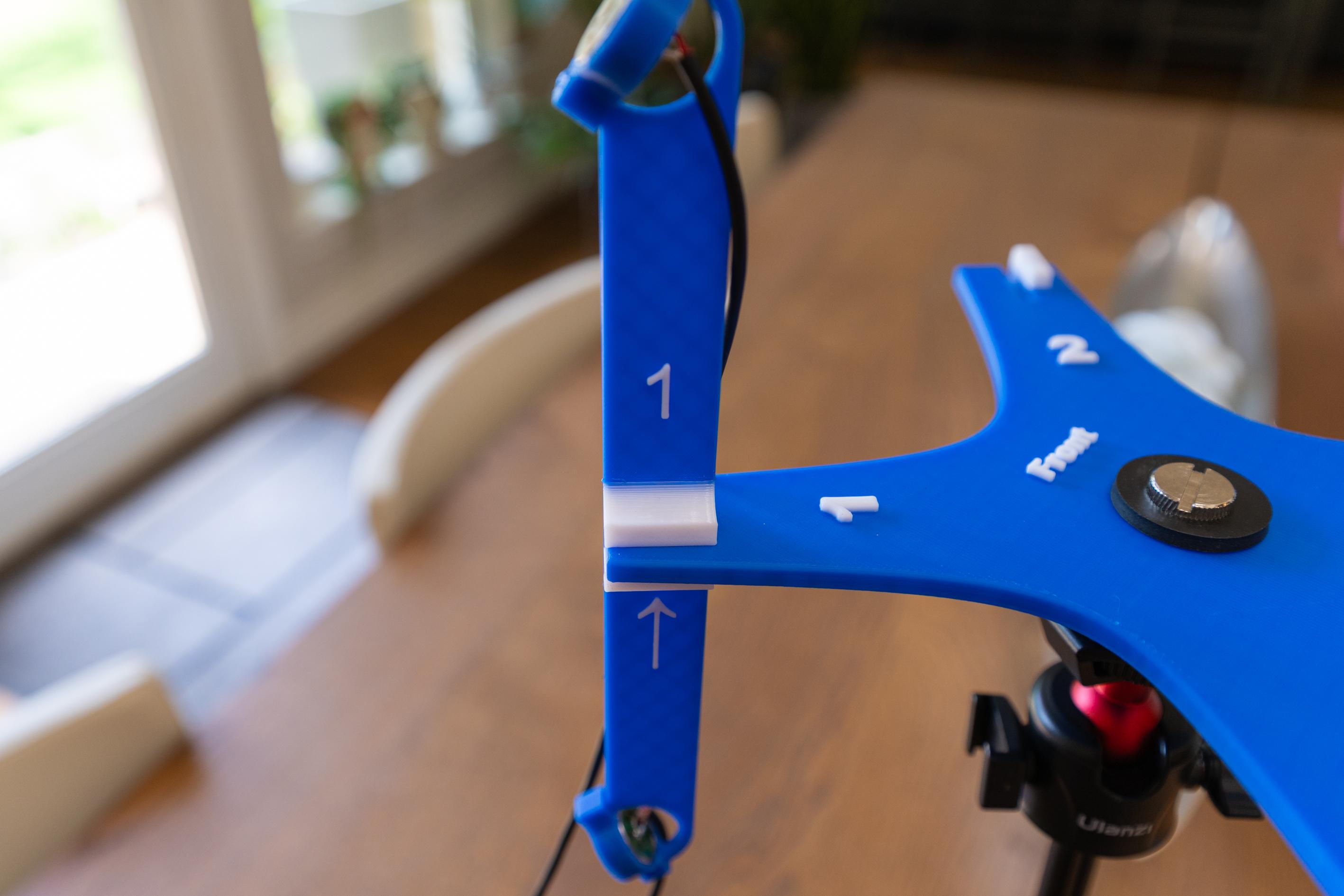
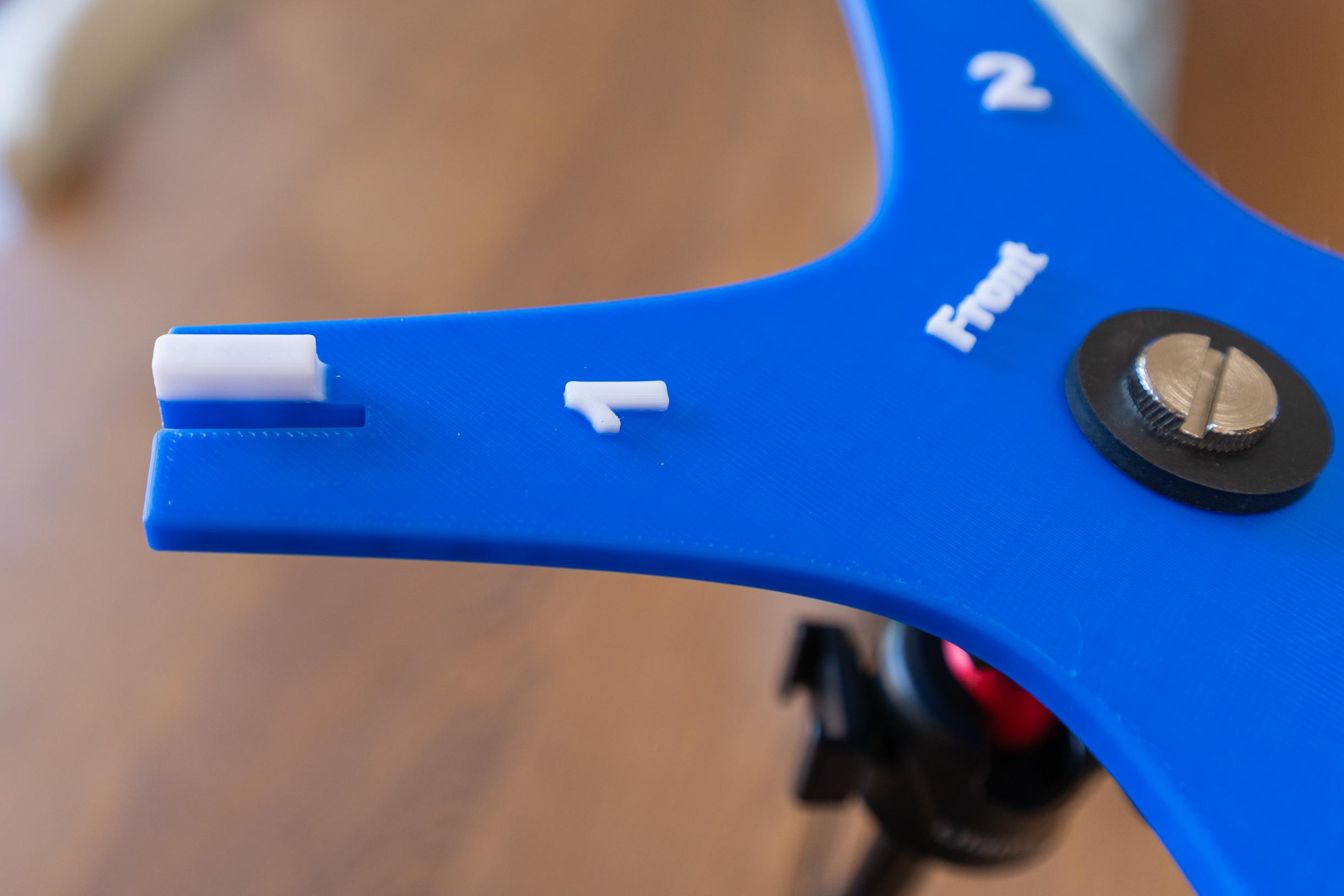
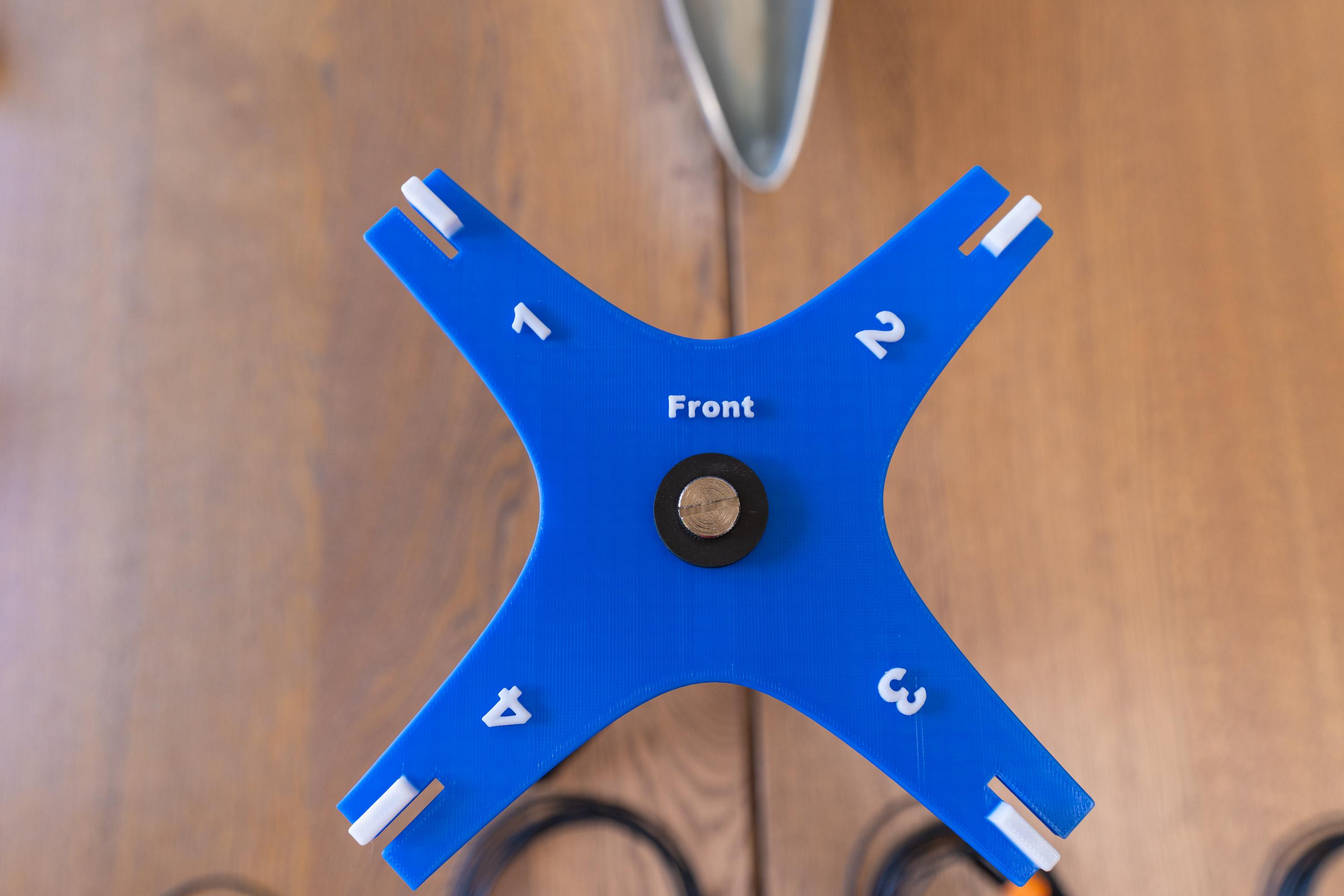
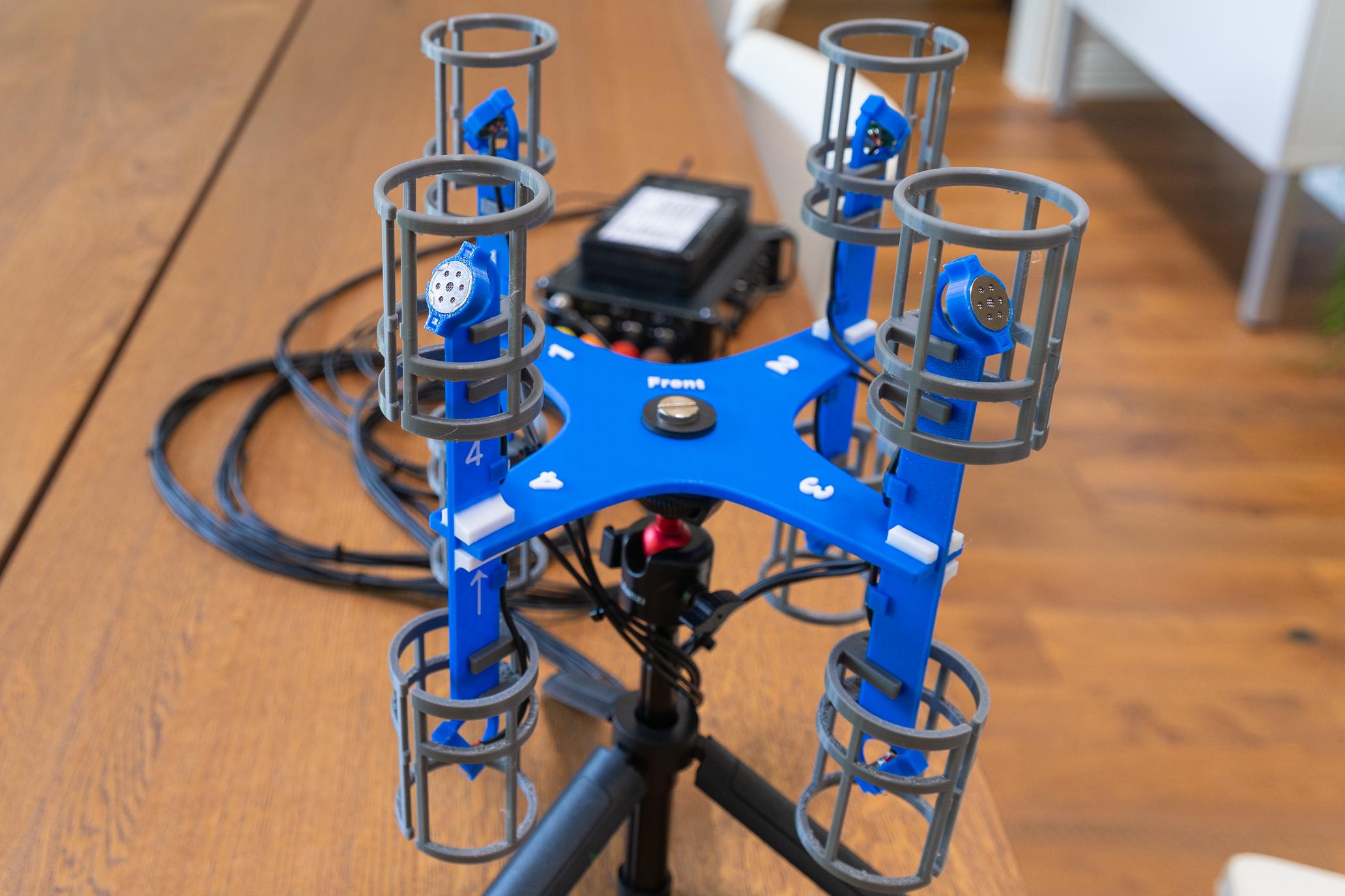
- The Base: This has a hole in the center to allow it to mount to a light stand using a ¼-20 screw. This uses a knurled nut, knurled bolt, and a rubber washer to adapt it to the light stand. See the parts list (and photos) for details. It is also labeled for position and numbered for the ORTF arms. Additionally there are features to help correctly put the arms in their correct orientation.
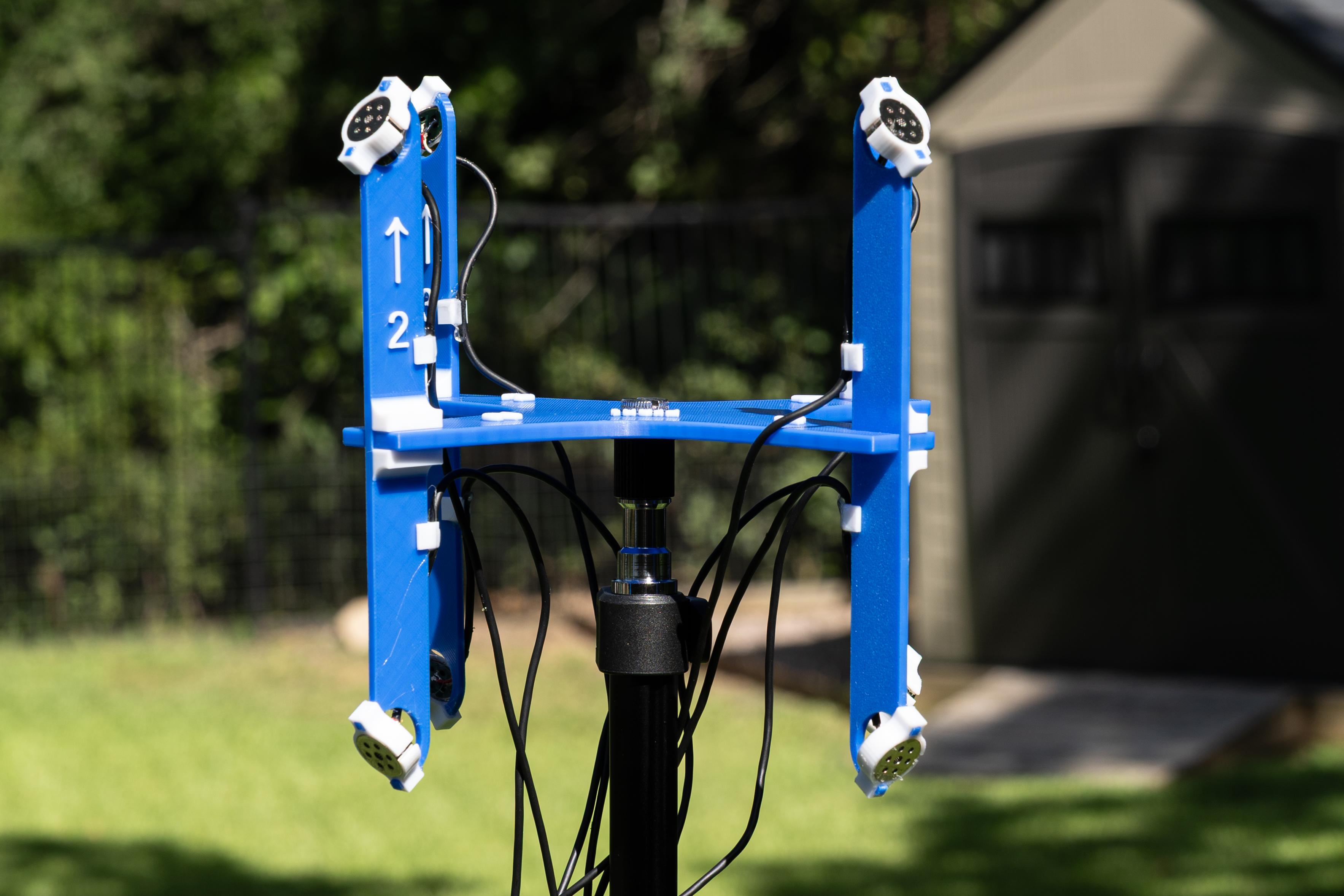
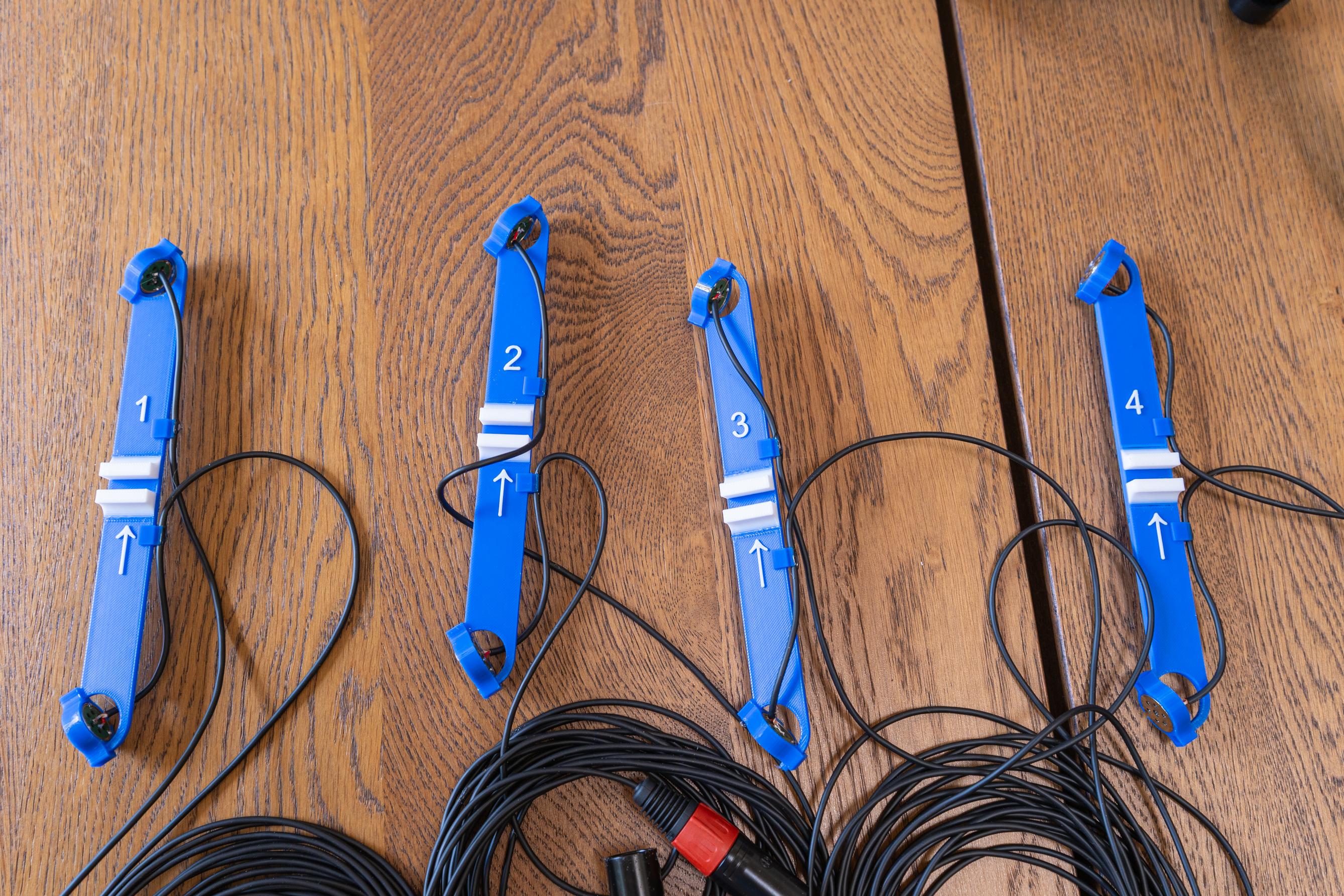
- The ORTF arms: There are four of these. Each one is numbered and has a directional arrow pointing up. There is also a tab printed on it that will prevent you from pointing it in the wrong direction. The ends have mounting points for the capsule holders that will angle them 55° up and down.
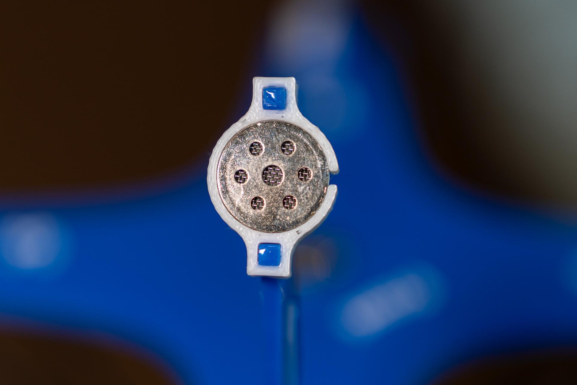
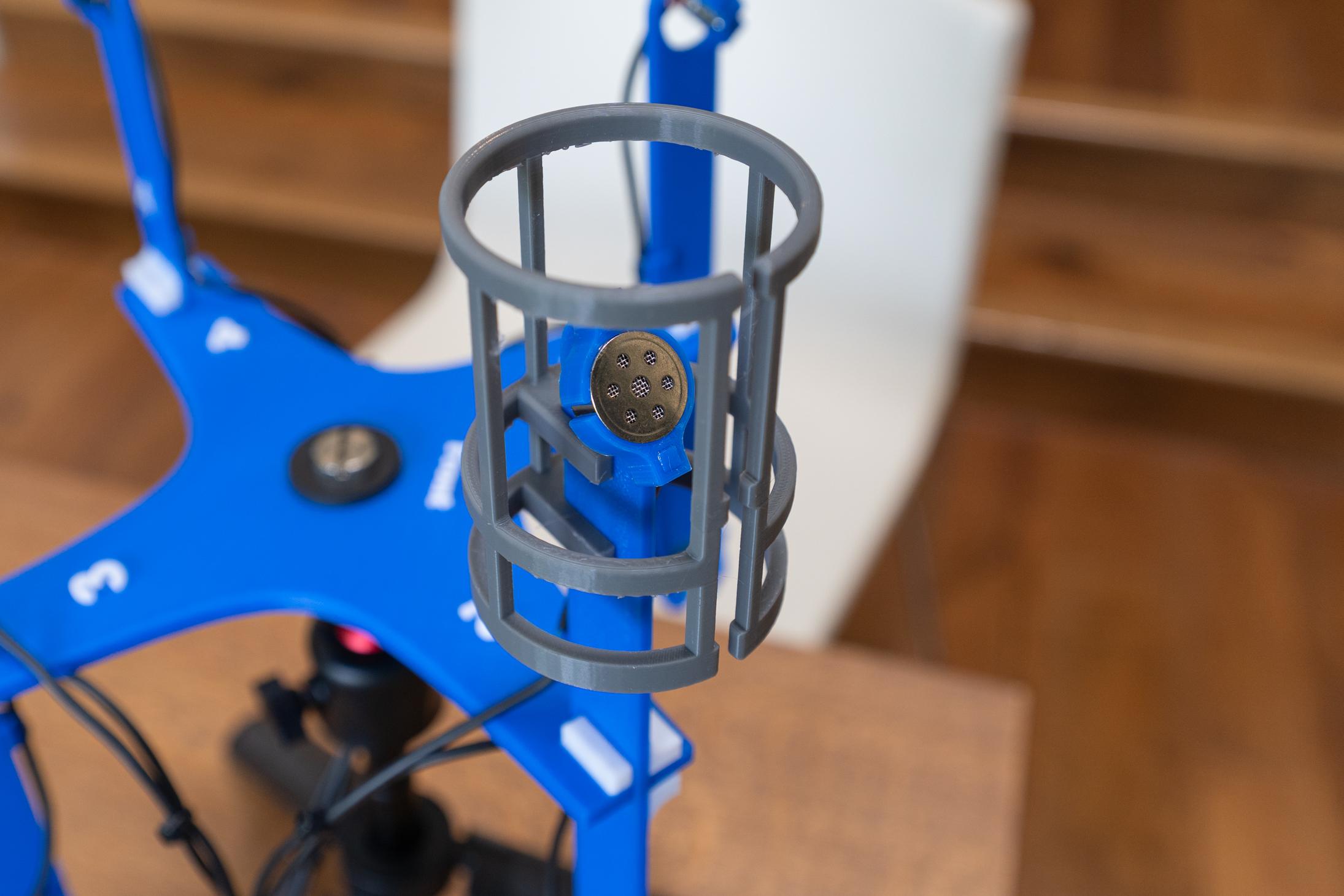
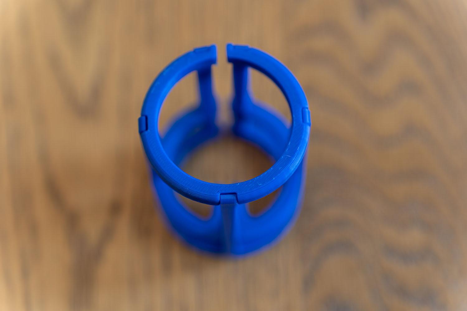
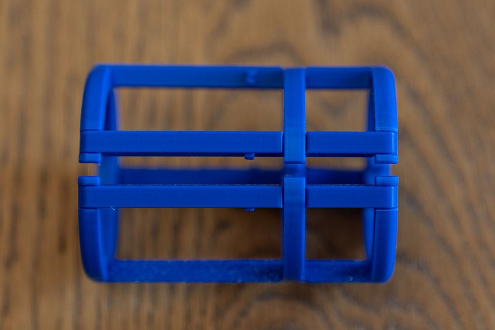
- The Capsule Holders: These have two cutouts for the arm ends and fit the capsules we are using.
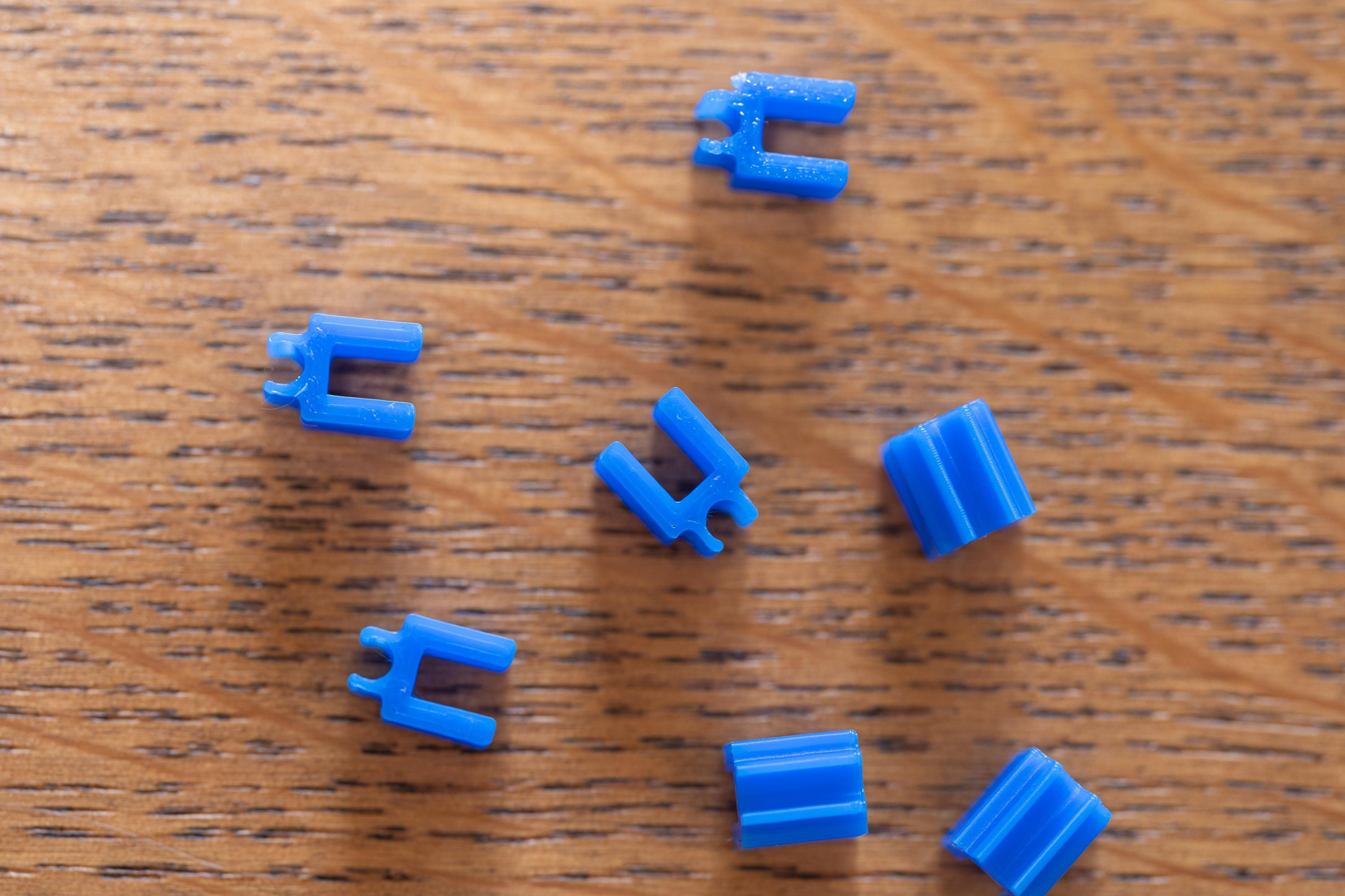
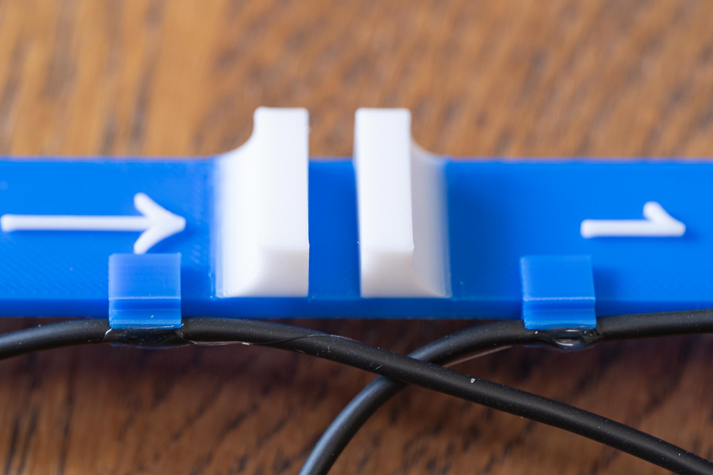
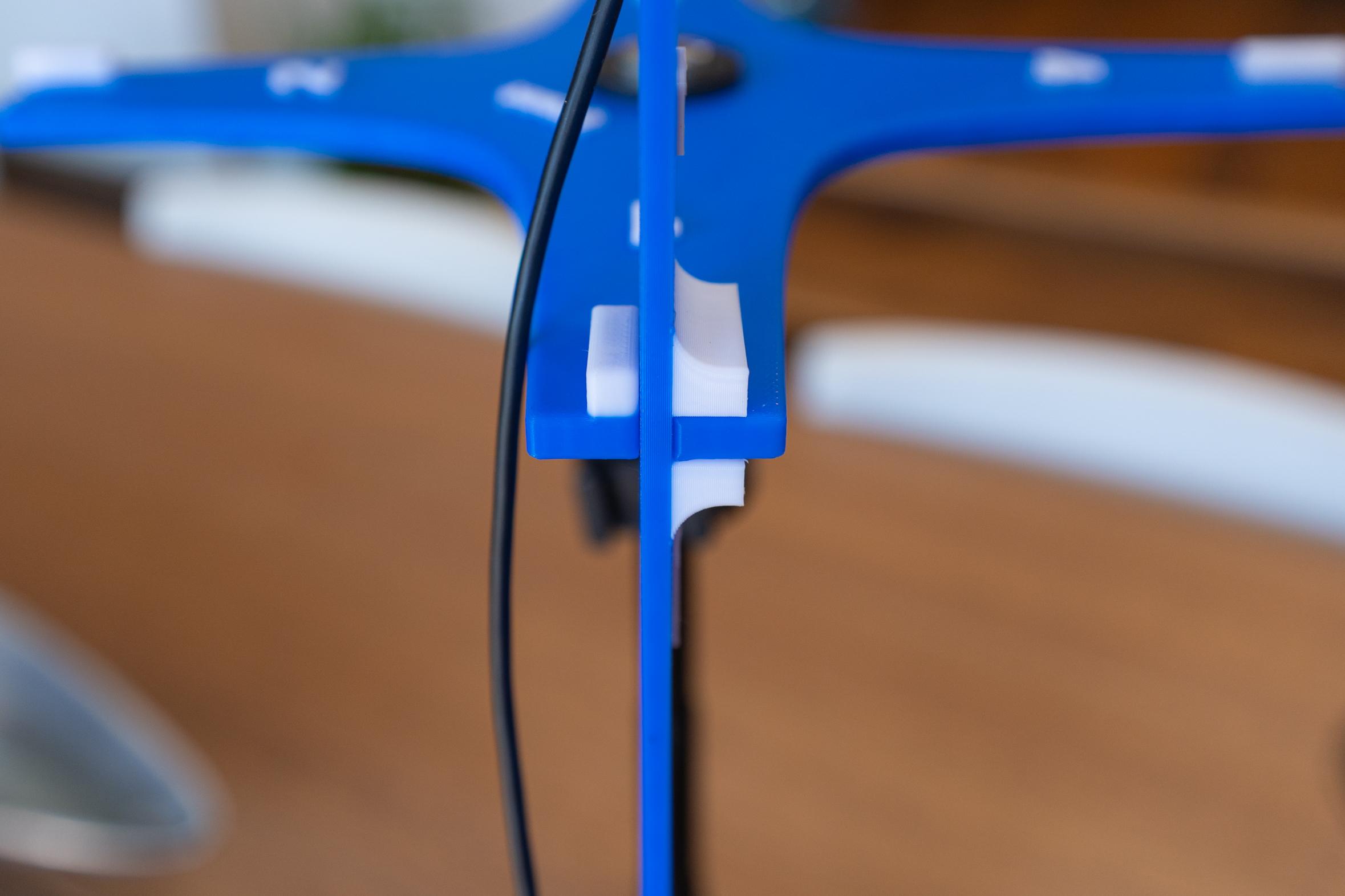
- Wire clips. These allow the Mogami wire to clip into the side and to press onto the ORTF Arms to hold the wires in place.
- Wind Protection: This is optional if you are only using the mic indoors. They fit onto the ORTF arms and allow a microphone “Dead Cat” furry windscreen to slide over them. See the parts list for the furry dead cat. There are two versions of this. One is complete but needs support when printed. The second I call the "flat" version as all the pieces print flat on the print bed then you assemble them "lincoln log" style.
Assembly:
- Put a small amount of E6000 glue on the inside of a capsule holder.
- Press the capsule in so it is flush.
- Repeat this for all 8 capsules.
- Let the E6000 dry ~ 4-6 hours.
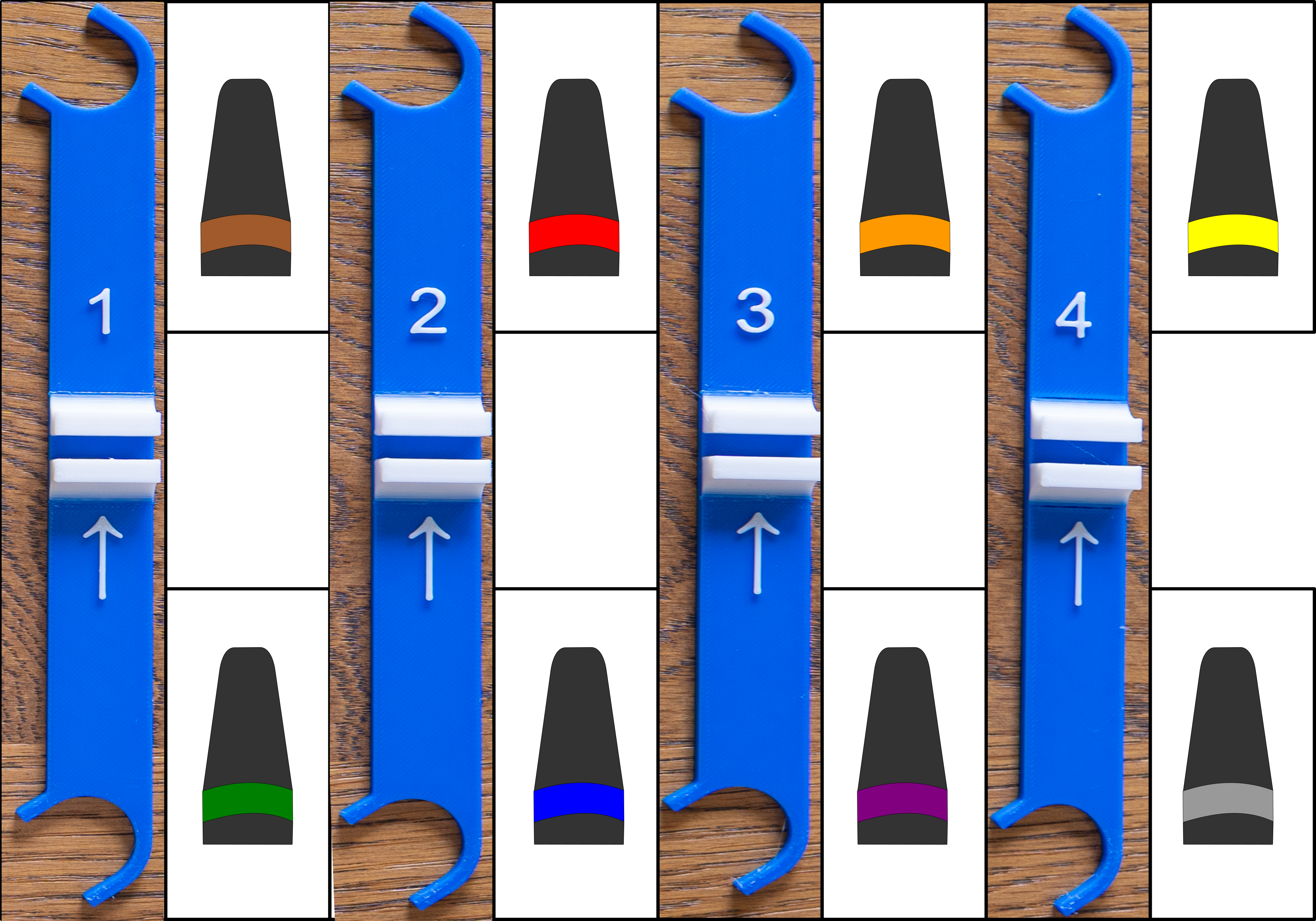
- Separate out each capsule so you can clearly see the associate XLR Boot color.
Note: Each Capsule assembly is color coded so it goes in the correct place. See the diagram to ensure you get this correct.

- Glue the capsule holders onto the ORTF Arms using E6000. Ensure that you have the correct color coding per above.
- Let these dry.
- Press on two wire clips on the back of each ORTF Arm. See the photos.
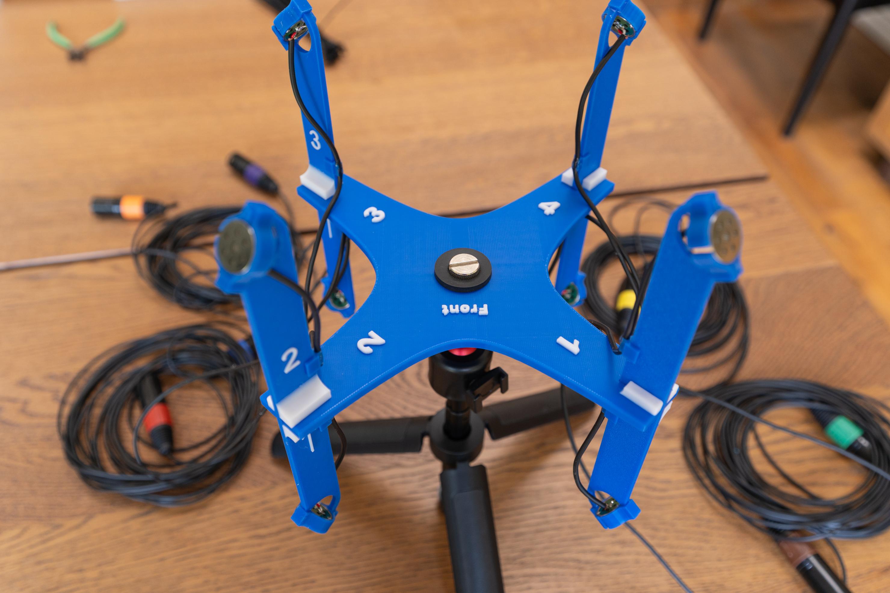
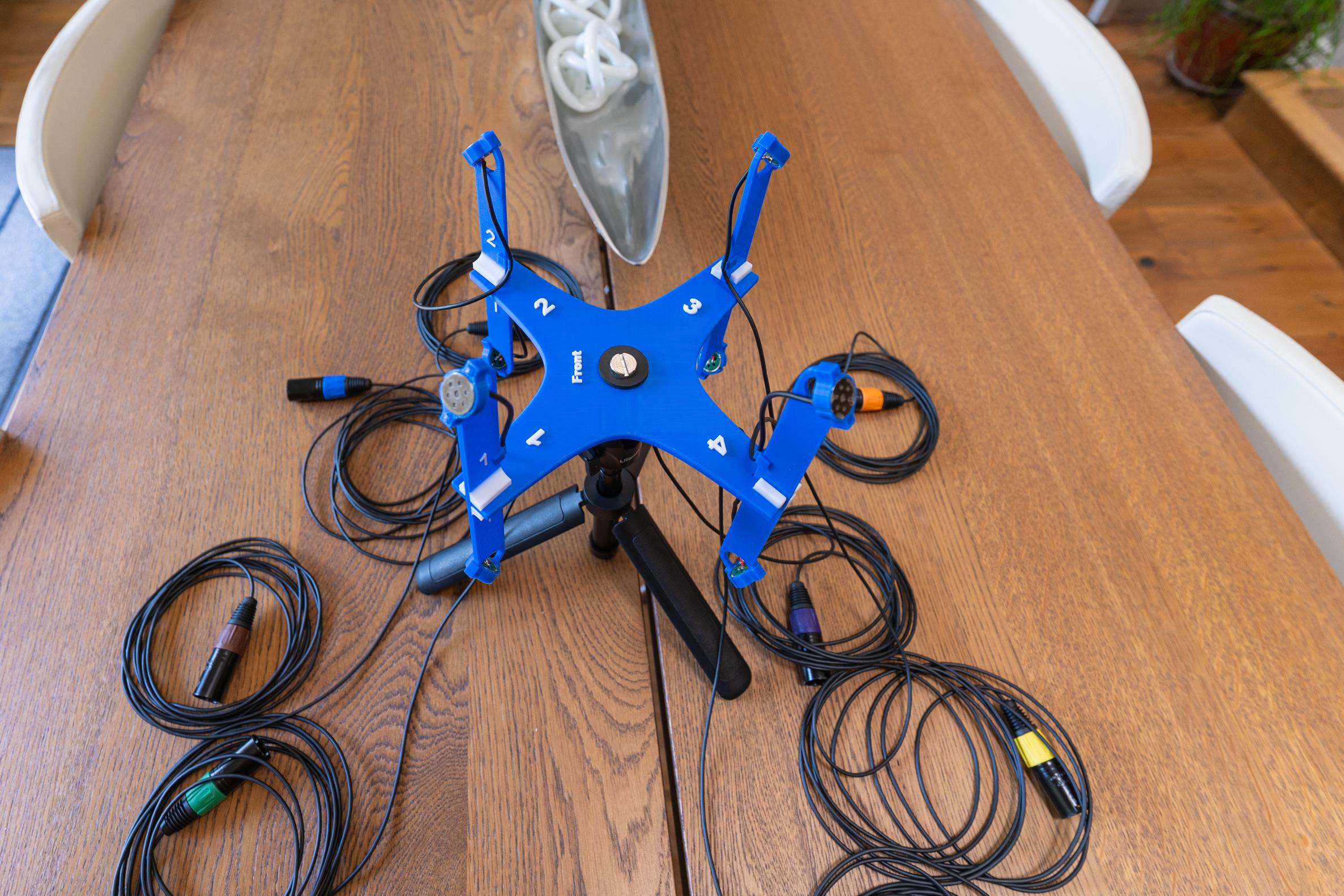
The next steps are easier if you mount the Base on a small tripod to hold all the arms.
- Slide each of the arms on the base matching their corresponding numbers.
- Separate out all 8 wires so that there are no tangles.
- Test each ORTF pair by connecting them to a recorder and listening with headphones.
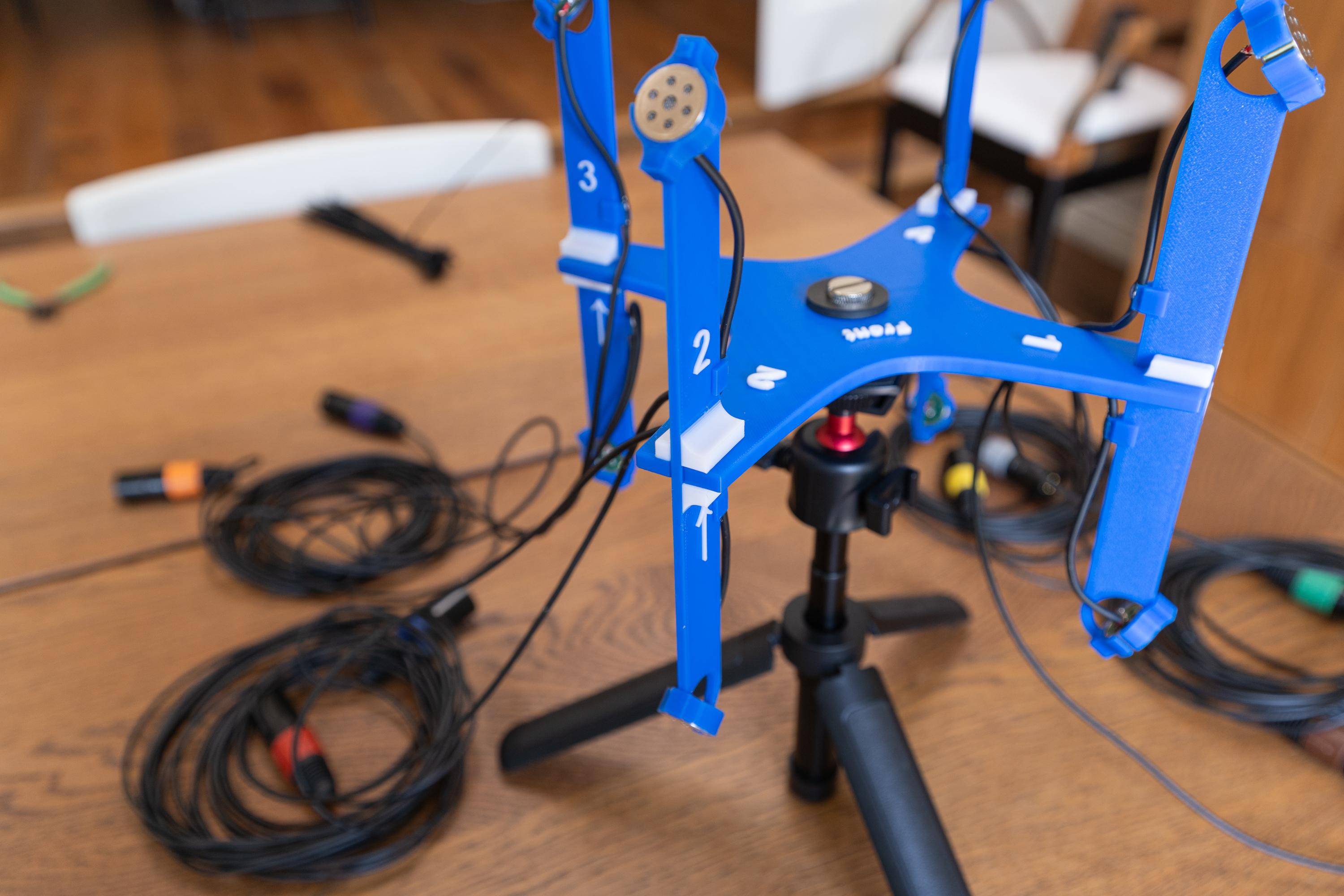
- After testing apply a small amount of E6000 to each of the wire clips to hold the wire in place. See the photos. Let that dry
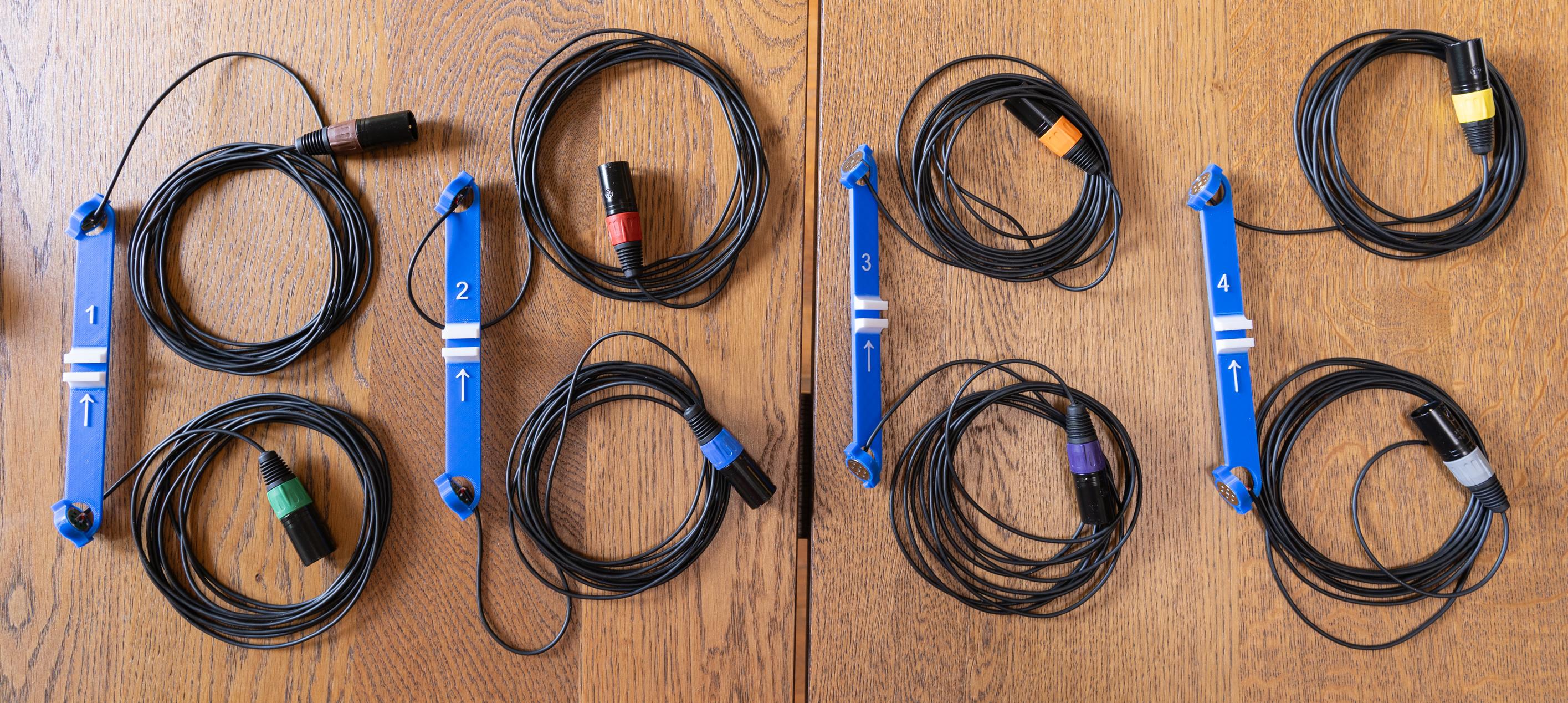
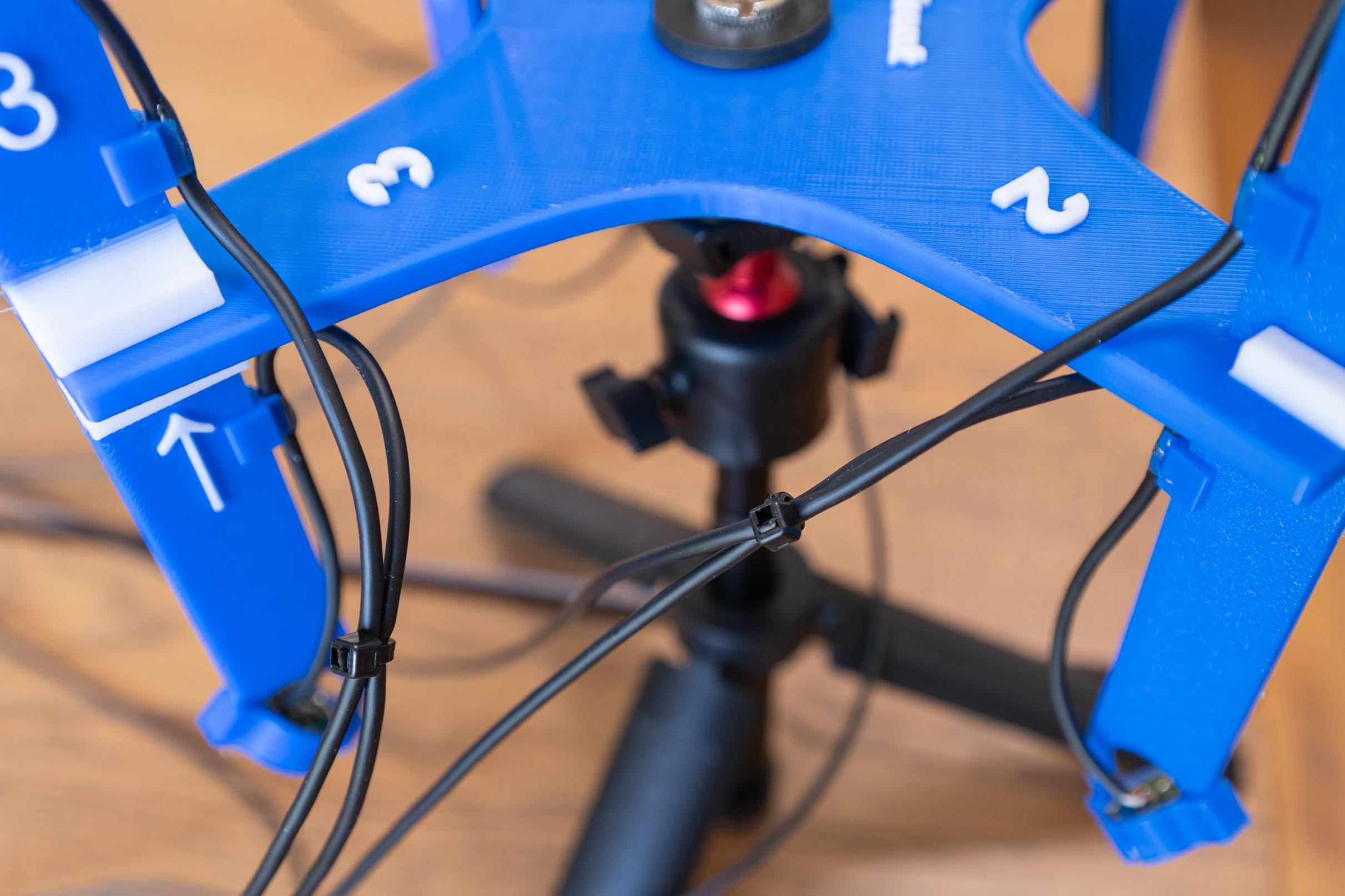
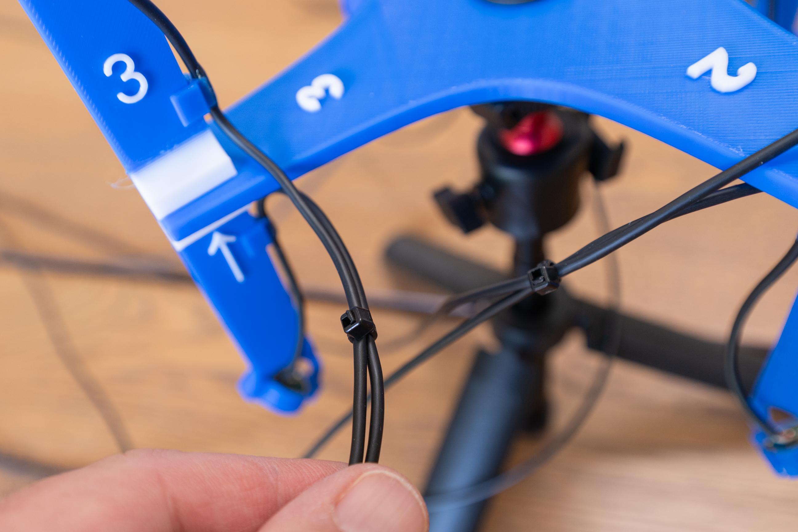
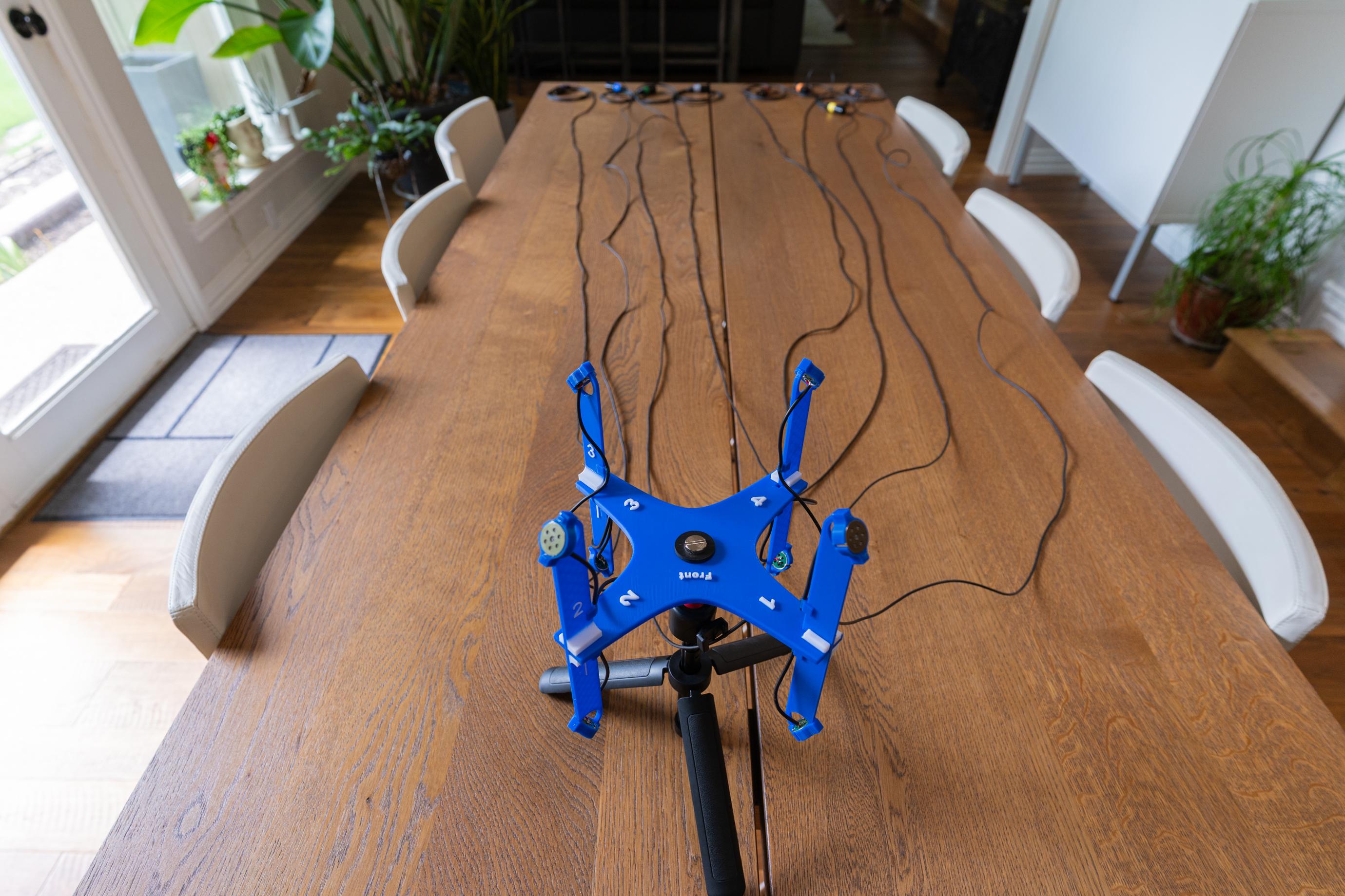
We are now going to dress in the wiring. This streamlines the setup and use of the microphone array. Each arm gets two tie wraps combining its two capsules. Then the “Left” and “Right” sides combine their four cables into one with a couple more tie wraps. Then all 8 cables get dressed into one cable leaving about two feet near the end. Now we split back out into two sets of four. In this case, we split out the incoming channels 1-4 and 5-8. This lets us plug into either a MicPre recorder or a Zoom F8nPro, Both those recorders have inputs 1-4 on one side of the recorder and 5-8 on the other side. See the photos for the specifics. This also allows us to slide the arms on and off for ease of storage and transportation.
- Layout the cables so that they are not tangled.
- Dress in and tie wrap each individual ORTF Arm with a tie wrap as shown.
- Add in one more tie wrap about 3”- 4” further down the wires.
- Repeat for the remaining three ORTF Arms.
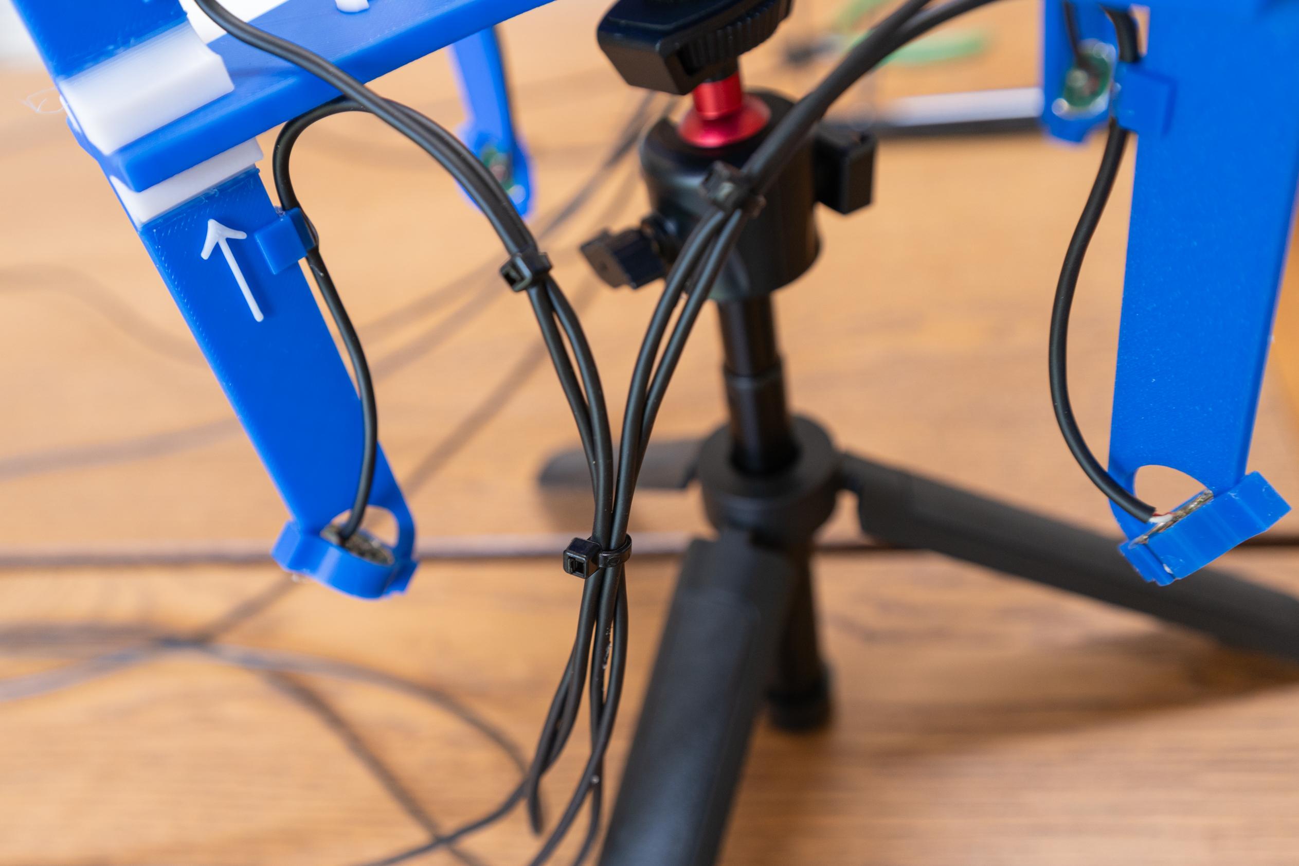
- Bring the wires from Arms 1 and 2 to one side of the base and tie wrap them together. See the photos. Add a second tie wrap about the same distance further.
- Repeat for Arms 3 and 4.
- Combine all the cables together into one bundle and place a tie wrap about 4-5” below that last one’s holding each set of four cables together.
- Continue adding tie wraps every 6-8” ensuring the cables are tight and even. Do this until there is about 24” of cables left.
- Separate out the rest of the cables into two bundles.
- Brown, Red, Orange and Yellow XLR’s
- Green, Blue, Purple and Grey XLR’s
- Continue tie wrapping the two bundles with a tie wrap every 4”- 6” until there is about 10” left. This should only take a few more tie wraps.
Congrats! If you aren't going to add wind protection, the build is finished.
Wind Protection

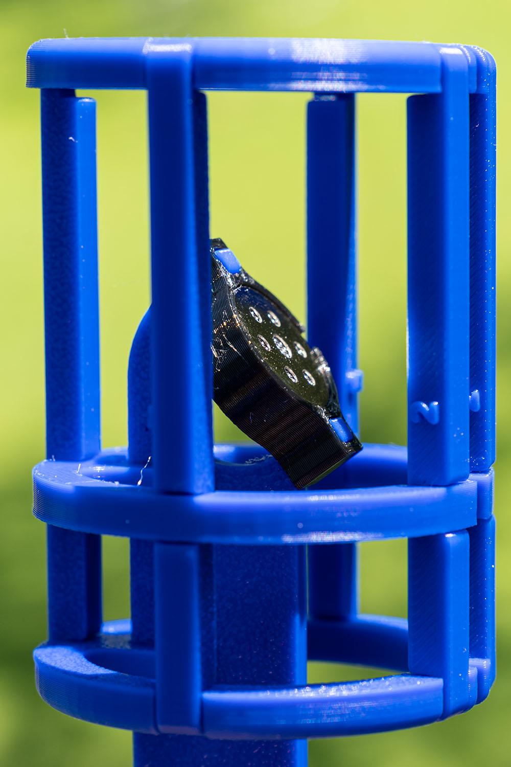
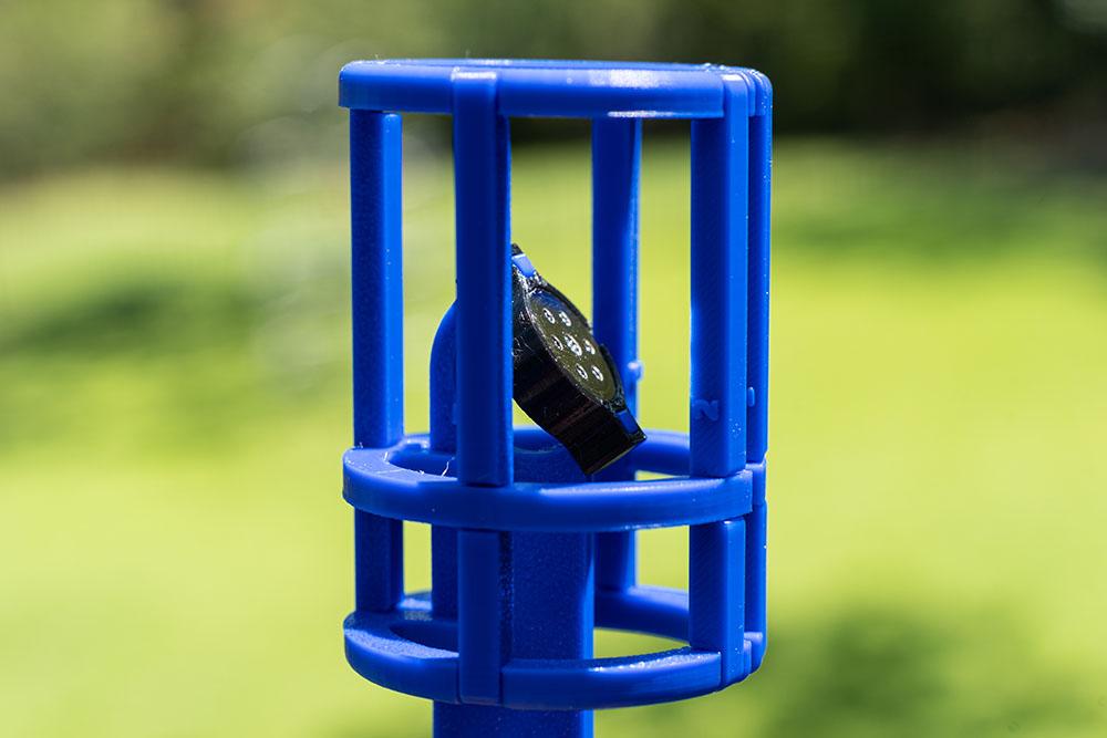
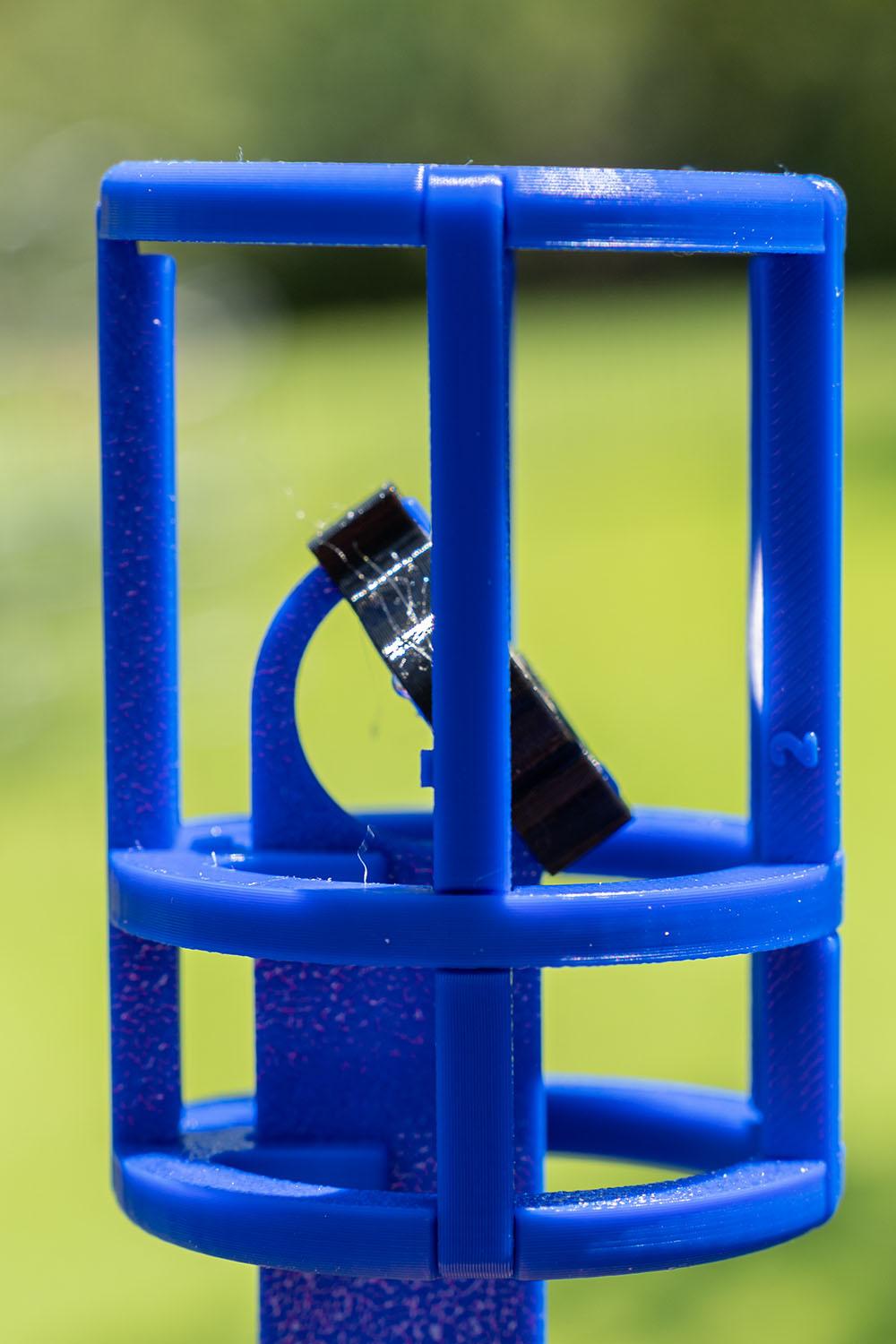

If you are planning on doing any kind of nature recording, you will need wind protection. I tried a couple DIY options for this. What I ended up with is 8 small furry “dead cats”. They can be purchased on AliExpress for less than $4 each. They are originally designed for an AT2020 microphone. I designed a frame that fits onto the ORTF Arms while centering the capsule in the airspace. They work really well although I would not use them in gale force winds.
There are two versions of print files for this. One requires supports while printing and I felt it was a pain to remove them so I designed a second version that prints flat but has to be assembled and glues. That takes less time than the support removal in my opinion. I am including both here.
Self contained: These take the longest to print and are the only ones that need support while printing. I printed them in sets of four.
Flat version:
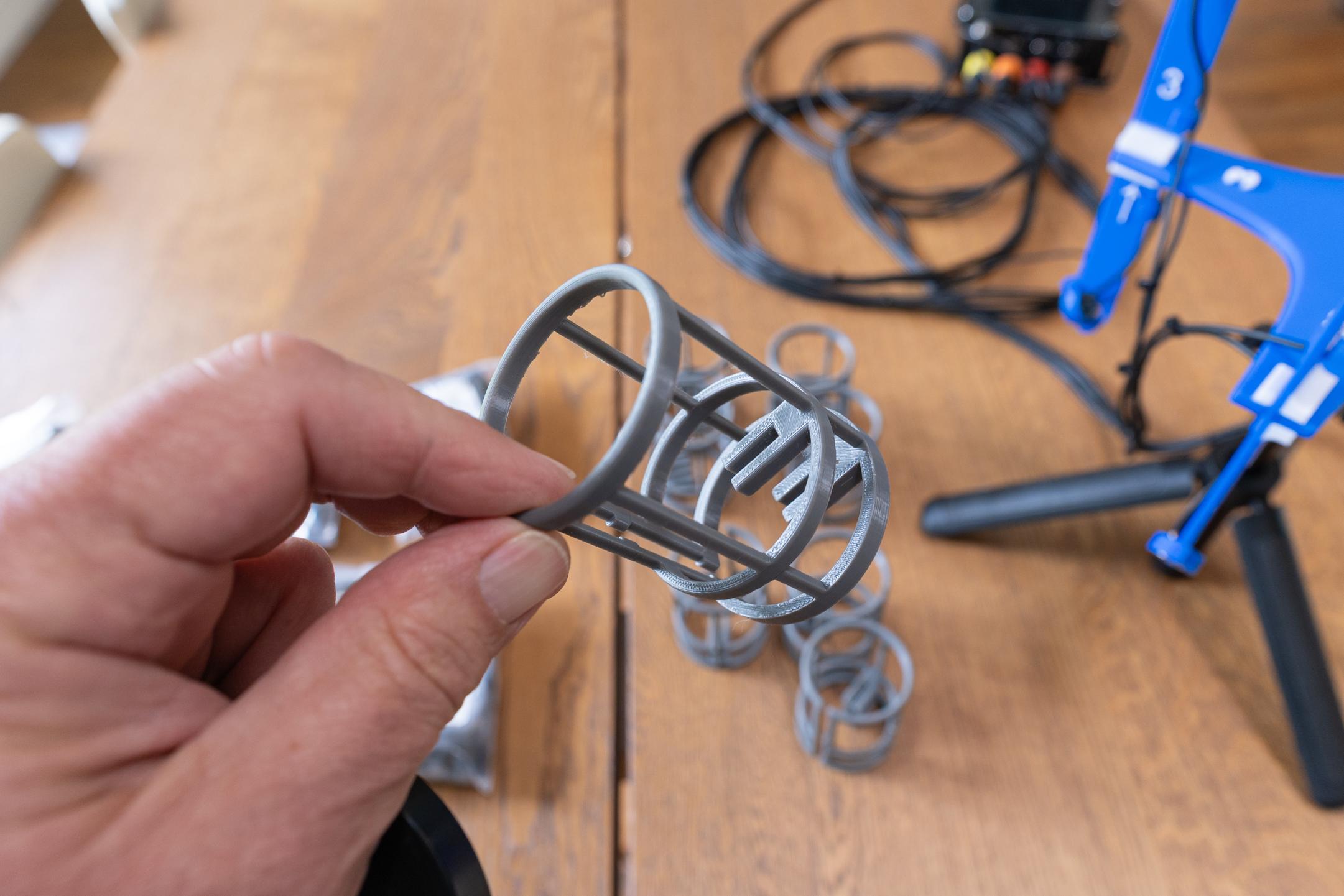
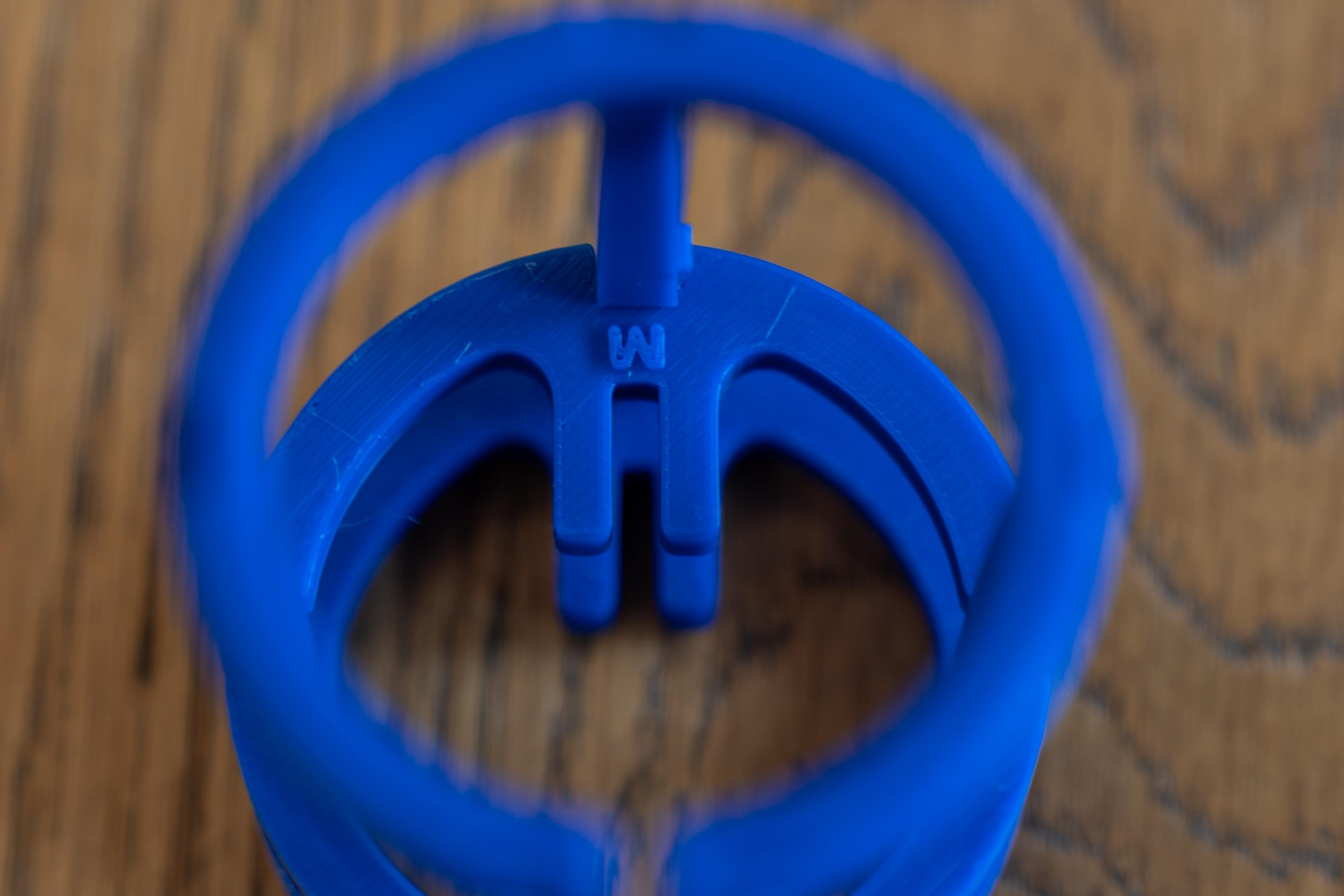
The wind protection is made from 8 3D printed frames. Then “dead cat” furry wind screens are slid over the frames. The frames are printed as shown below and then assembled with some E6000 glue at the joints. There are three rings:
- Bottom “B” (The B faces down when assembled)
- Middle with “M” printed on it
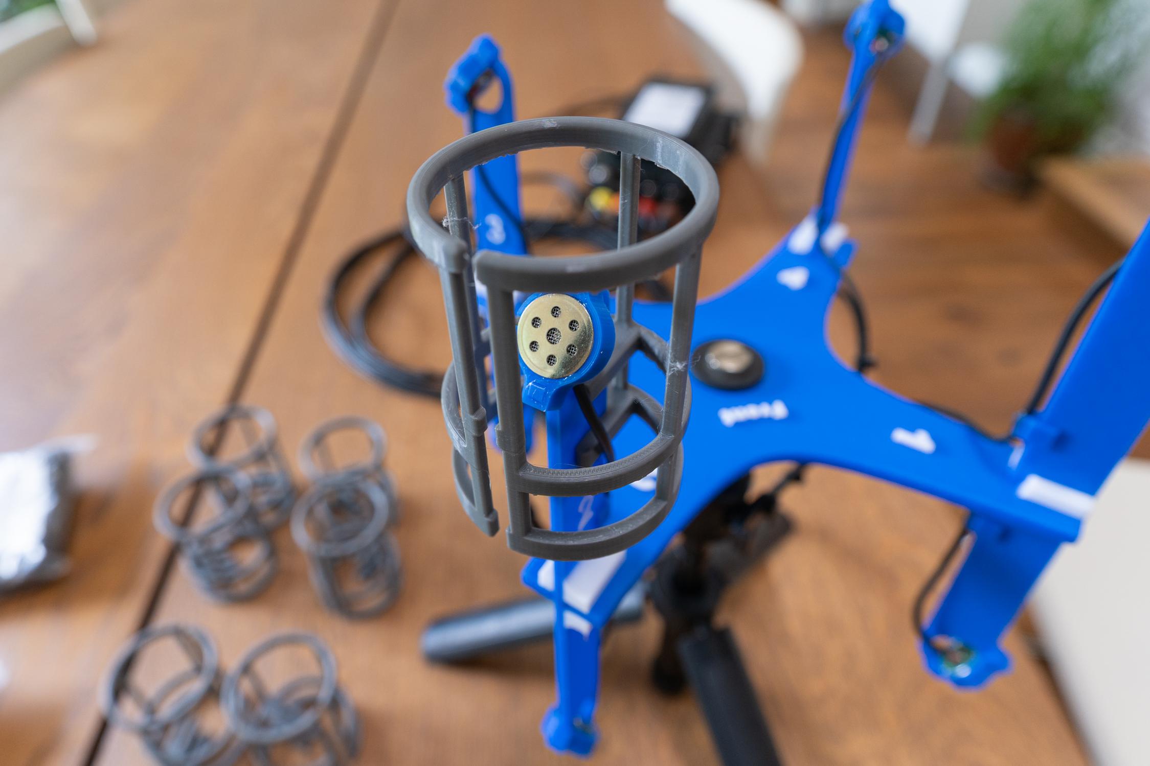
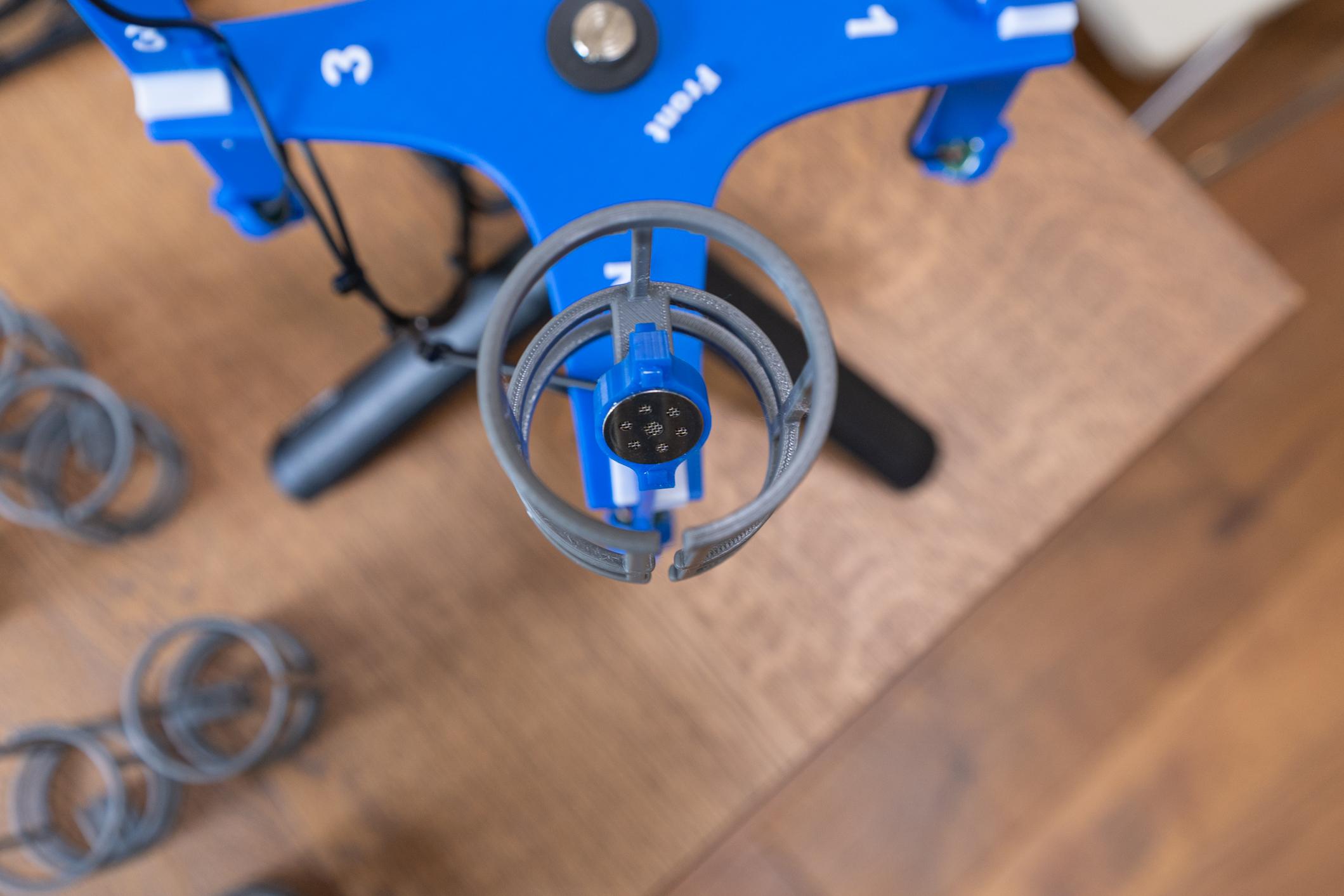
- A top with no labelOnce the eight frames are assembled, they snug onto the ORTF arms as shown. Use some E6000 glue on the edge of the joint to lock it in place. After the glue dries, you can slip on the actual furry windscreen.
There will be a bit of a gap at the bottom of the furry section. You can tighten it with a rubber band or hair band.
Recording


Recording:
Now the fun part! Thanks to modern field recorders available such as the MixPre 10T and the Zoom F8n Pro, we have this part covered. The mic will also work with a DAW and an 8 channel analog interface. It is actually easier to use with the field recorders and is my preferred method. Both support 32 Bit Float recording as well. Let's look at settings first:
For either the MixPre or the Zoom
- Ensure Phantom Power is on and set to 48V. P24 will not work with the resistor value we have selected.
- Set up Recording to save as one multichannel wav file.
- Link inputs 1-8 for gain/trim control. This way one adjustment sets the gain for all 8, and keeps them all set to the same gain.
- The file size can get large so I tend to record at 48Khz, Sometimes 96Khz if I am using this as part of a larger setup.
For a DAW and recording to a Mac or PC
- Ensure Phantom Power is on and set to 48V
- Manually set each mic preamp gain identically (or as close as you can get)
- Record normally.
For either case. Do a quick check of VU metering or headphone listening to ensure all is working.
This is just the mechanics of getting Maurice recording. This is the tip of the iceberg.
Mixing
Mixing is where the real fun starts. Remember we are mixing immersively here. Everything I am going to cover assumes you are mixing into 7.1.4. The principles presented apply to larger setups as well. We will look into rendering to binaural in stereo but that Maurice really shines when mixed to 7.1.4.
Lets review how we have things labeled and where the mics are pointing

With Maurice pointing forward we have Arm 1 facing left 45° and with it Mic1 faces up 55° Mic 5 faces down 55°. Arm 2 with its associated mics face right 45°. The best way to look at this is using the terms Azimuth and Elevation. Azimuth and Elevation are angles used to specify the position of an object in a spherical coordinate system, usually within the context of astronomy or navigation. Azimuth is the horizontal angle, measured clockwise from a reference direction (usually north), while elevation (or altitude) is the vertical angle, measured upward from the horizon. So in our case Arm 1 is: Azimuth 315°, Elevation 55°. Interestingly, most plugins don't quite follow that nomenclature. They look more like this:

Here is the Sparta Binauralizer plug in setup to decode the array. Maurice is natively 4.0.4 as there four mics for height and four for ear level. For mixing into 7.1.4 we can map the 8 channels to their equivalent ones. To do that in Reaper we use an included plug in called “Channel Mapper Downmixer” It allows you to quickly take multichannel audio and rearrange which channels go where. It is a quite powerful little plugin. Note the “Unmapped outs” section. For what we are doing, you need to select Zero out. Otherwise you will send the original channel mappings through as well.

Here is how we need to map Maurice through:

Putting that into Reapers Channel Mapper Plugin we get:
These are the absolute basics of mixing with this microphone.
Because the mic is symmetrical, The sound field can be easily rotated in post when rendering down to binaural. The video includes a demo of that. Our next step will help using it.
Using Maurice
Usage:
Maurice can be used stand alone to capture audio immersively making him perfect for field and nature recording.
Microphone placement:
One of the key components of recording is microphone placement. For traditional stereo recording there is a wealth of knowledge and decades of experience to rely on. For immersive audio some of that applies but there are other factors to take into account. The biggest one in my mind is the overall sound field you are trying to capture. We are talking about immersive audio here… Remember, you have sound coming at the mic from all directions. The capsules we are using work really well for ORTF and the way the array is designed we are actually getting better separation of height from Left/Right.
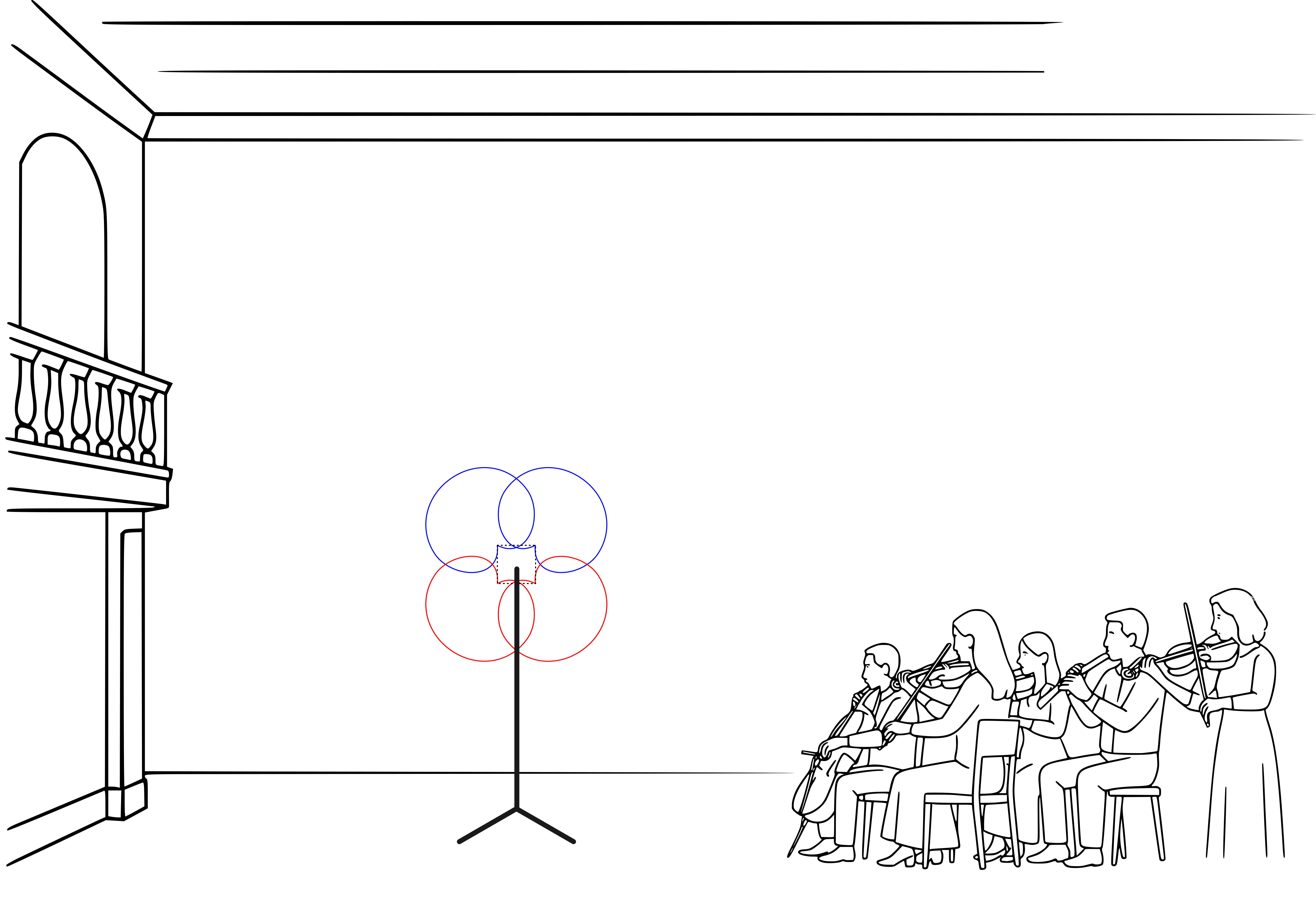
I have had a chance to record an Orchestra and a decent sized Choir with this mic. I placed it in front of the conductor as close to the “center” of the semicircle of musicians. This isn't your typical vantage point or mic placement but I love the results. It is wide, spacious, and well… immersive. Which is the whole point here!
Because the microphone array is pretty compact it lends itself to going into many places a large array could not. I’m looking forward to what people who build this end up recording with it.
My biggest use for this is part of a larger recording setup. I combine it with traditional mic techniques but with the thought process of mixing into immersive. Maurice provides a solid immersive representation of the whole sound field. Then I will add in ORTF mains (I did say that was my favorite mic technique!) And left and right side microphones. These are just starting points. There is a lot to be explored here.
Field recording is another great use for Maurice. You will need wind protection for this. One of the nice things of the design is that you can remove the ORTF Arms and make the rig pretty compact for those long hikes into the rain forest.
Summary and Going Further
Maurice is a great entry into immersive recording. The mic has very decent specs and sounds great. The capsules used sound amazing in ORTF and I originally used them in my camera mount ORTF setup. Maurice just takes four sets of those and rotates them 90° to capture the same sonic image vertically. It does this differently than an Ambisonic microphone because it is non-coincident. It provides both interaural timing and level differences from each mic capsule.
There are other small mic arrays out there. The most famous one is the Schoeps ORTF3D microphone. It was my inspiration for this mic. I have discussed the design with Helmut Wittek, of Schoeps microphones at a couple AES events. Originally I designed a setup matching the angles of the Schoeps mic. They are using supercardioid capsules in that design which work for their specific capsule placements. It also lets them “flatten” their mic as the height microphones face upward and are physically next to the front and rear facing capsules. If you have seen Blade Runner 2049 then you have heard this mic. It was used to immersively record the rain used in the movie. Another entrant into this style microphone is from Audio Technica with their BP3600 This uses hypercardioid capsules. I have seen the mic at several AES events but have not heard it yet.
Schoeps makes absolutely some of the best microphones in the world and have been doing so for 65 years. Their ORTF3D rig is about $20K. The Audio Technica microphone is listed at $5679 at the time I am writing this. Maurice can be built for substantially less than that, letting you start your journey into immersive recording. Where will it take you?
Here are some demo files recorded with Maurice. There is a Reaper session with three 8 channel wav files of an Orchestra, a Choir and a Pipe Organ.