Mecanum Drive Robotic Arm Manipulator
by svvetal14 in Circuits > Raspberry Pi
27313 Views, 153 Favorites, 0 Comments
Mecanum Drive Robotic Arm Manipulator


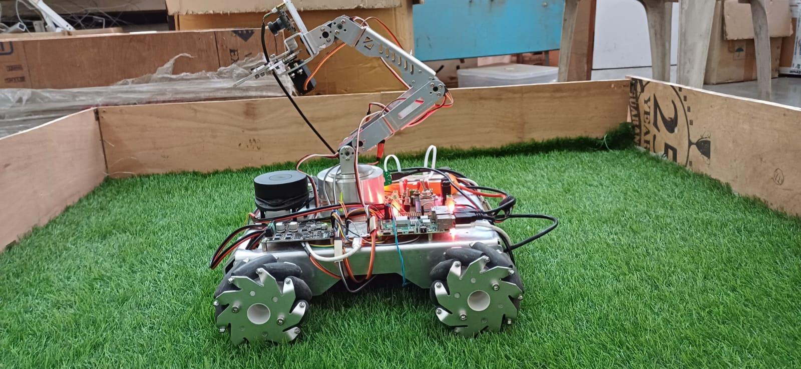


In addition to the advancements in mobility and control facilitated by the integration of Internet of Things (IoT) technology and 4-wheel Mecanum drive systems, there has also been notable progress in the development of robotic arms utilizing this innovative drive system.
Mecanum drive technology, renowned for its ability to enable omnidirectional movement, presents a promising solution for enhancing the versatility and agility of robotic arms. By incorporating Mecanum wheels into the base of robotic arms, engineers have been able to create manipulators capable of navigating complex environments with remarkable precision and dexterity.
The integration of IoT capabilities further enhances the functionality and adaptability of these robotic arms. Through real-time data collection and analysis, IoT-enabled robotic arms equipped with Mecanum drive systems can intelligently respond to changes in their surroundings, optimize task performance, and collaborate seamlessly with other IoT-connected devices and systems.
Applications for IoT-enabled Mecanum drive robotic arms span a wide range of industries and tasks. In manufacturing, these arms can efficiently handle materials and components in dynamic production environments, adapting to variations in workflow and demand. In logistics, they can streamline warehouse operations by autonomously sorting and transporting items with speed and accuracy. Additionally, in healthcare settings, these robotic arms can assist with delicate procedures, such as surgical operations or patient care tasks, with enhanced precision and safety.
The development of robotic arms leveraging IoT technology and Mecanum drive systems underscores the ongoing evolution of robotics towards more intelligent, adaptable, and collaborative systems. By harnessing the power of these technologies, researchers and engineers are poised to unlock new possibilities for automation across diverse fields, ultimately driving innovation and efficiency in industry and society.
Applications Targeted:
- Warehouse Management and Material Tracking. (Using OpenCV)
- Basic Pick and Place Tasks.
- Capture Package Aruco Marker and perform specific tasks such as Inventory Updation/Verification.
- Autonomous Navigation through warehouse (SLAM)
- Obstacle Avoidance and Detection.
- Live Camera Feed for User Visuality.
- Path Planning.
- Realtime Robot Data Display on Web/App Dashboard.
Supplies
HARDWARE REQUIREMENTS :
- Raspberry Pi Microcontroller (4B 8GB RAM) x 1
- USB Camera Module (OV2710) x 1
- A1 RP-Lidar x 1
- 12V DC Motor (330RPM 2.2Kgcm) x 4
- Mecanum Wheels x 4
- Cytron Motor Driver (MDD10A Dual Channel) x 2
- 12V Power Distribution PCB x 1
- 5-30V Buck Converter x 1
- 16-Channel Servo HAT x 1
- MPU6050 Accelerometer and Gyroscope x 1
- USB Wireless Mouse x 1
- 12V Li-Po Battery x 1
- TF-Luna Distance Sensor x 1
- ESP32 Microcontroller x 1
- Servo Motor (MG996) x 2
- Servo Motor (RDS3225 25Kg) x 3
- Base Rotate Component (Lathe) x 1
- Ball Bearing (52 x 40 x 7) x 1
- Robot Chassis (Aluminium 3mm Laser Cutting) x 1
- Robotic Arm (Aluminium 2mm Laser Cutting) x 1
- Robotic Arm Gripper (Aluminium 3mm Laser Cutting) x 1
- Lidar B-Type USB Data Cable x 1
- ESP32 Power and B-Type USB Cable x 1
- Camera USB Cable x 1
- USB Mouse Receiver x 1
- Mouse Holder (3D Printed) x 1
- Red-Black Connecting wires (4mm Guage) x 1
- Jumper Wires x 20
- Alan Bolts (M2, M3, M4, M5) x 50
- Nuts (M2, M3, M3, M4, M5) x 50
SOFTWARE REQUIREMENTS :
- Autodesk Fusion 360 (CAD Designing)
- Autodesk Eagle (PCB Designing)
- ROS2 Humble (Robotic Operating System)
- Gazebo (Robot Simulation)
- RViz (ROS Visualization Tool)
- MoveIt (Robotic Arm Simulaton and Trajectory Planning)
- OpenCV (Aruco Marker Detection)
- Flask (Website)
- AJAX (Realtime data upload)
- VS Code (Python Programming for ROS2)
- Arduino IDE (ESP32 Programming)
- Ubuntu 22.04 (Operating System)
Dependencies and Pre- Requisites
- Raspberry Pi (4B 8GB RAM) - 32 GB SD Card
- Flash the SD Card with Ubuntu 22.04 Operating System Compatible with ROS2 Humble
Link to Ubuntu Image (Server Image) : https://ubuntu.com/download/raspberry-pi
Alternative Way - Raspi Imager Application : Enter the below command to download the Application
sudo snap install rpi-imager
Use this application to flash the os into the SD Card and set the initial WiFi SSID and Password to the network to which your raspberry pi should be connected at first.
After setting up the Operating system now its time to download the ROS2 Humble and OpenCV used to run ROS2 Applications on our Raspberry Pi.
locale  # check for UTF-8


sudo apt update && sudo apt install locales
sudo locale-gen en_US en_US.UTF-8
sudo update-locale LC_ALL=en_US.UTF-8 LANG=en_US.UTF-8
export LANG=en_US.UTF-8


locale  # verify settings

#First ensure that the Ubuntu Universe repository is enabled
sudo apt install software-properties-common
sudo add-apt-repository universe

#Now add the ROS 2 GPG key with apt.
sudo apt update && sudo apt install curl -y
sudo curl -sSL https://raw.githubusercontent.com/ros/rosdistro/master/ros.key -o /usr/share/keyrings/ros-archive-keyring.gpg

#Then add the repository to your sources list.
echo "deb [arch=$(dpkg --print-architecture) signed-by=/usr/share/keyrings/ros-archive-keyring.gpg] http://packages.ros.org/ros2/ubuntu $(. /etc/os-release && echo $UBUNTU_CODENAME) main" | sudo tee /etc/apt/sources.list.d/ros2.list > /dev/null

#Update your apt repository caches after setting up the repositories.
sudo apt update

#ROS 2 packages are built on frequently updated Ubuntu systems.
sudo apt upgrade

#ROS-Base Install (Bare Bones): Communication libraries, message packages, command line tools. No GUI tools.
sudo apt install ros-humble-ros-base

#Development tools: Compilers and other tools to build ROS packages
sudo apt install ros-dev-tools

#Set up your environment by sourcing the following file.
# Replace ".bash" with your shell if you're not using bash
# Possible values are: setup.bash, setup.sh, setup.zsh
source /opt/ros/humble/setup.bash
For more details about ROS2 Humble Installation visit its Documentation Page : https://docs.ros.org/en/humble/Installation/Ubuntu-Install-Debians.html
Command to install OpenCV Compatible with ROS2 Humble :
sudo apt install python3-pip

pip3 install opencv-contrib-python==4.7.0.72
pip3 install numpy==1.21.5
With this setup we are ready to move ahead...!!!
Designing the Robot Chassis


- Designed the Robot Locomotion Chassis using the Autodesk Fusion 360 Software for Mechanical designing of the Chassis in order to provide good stability for the 4 wheel mecanun drive taking into consideration the Payload and Torque required by the Robot.
- The material used is Aluminium (3mm thickness) and the whole of the chassis has been developed using the Laser Cutting Technology for precision work and attention to detail for a robust design.
- Utilised the Fusion 360 Sheet Metal features to develop the compatible files used for laser cutting.
- The provided features such as Sheet Metal along with the ability to create Flanges and at the last the Flat Pattern feature helps in making the 2D pattern of the desired sheet of metal and also provides with the bending lines for ease of the manufacturer.
- There are also 4 couplings made in order to attach the wheel with the motor shaft. The Lathe work required is also developed in Fusion 360 and is thus manufactured using a Lathe Machine.
Link to view the Robot Locomotion Design : https://a360.co/4aQWn7F
Designing the Robotic Arm


- The Robotic Arm is designed such that it is able to cover maximum radius from the point of origin of the Robotic Arm depending upon the Payload required.
- The Arm is designed such that it poses the capacity to handle a load of upto 700-800gms depending upon the Targeted Application.
- The material used is Aluminium (2mm Thickness) which provides a good support and a greater stability in order to handle some of the heavy weighted components such as the servo motors along with the gripper assembly. The design developed is able to effectively distribute the overall load across the mechanical linkages.
- A solid base for rotating the entire Robotic Arm about its base is also made in order to provide a rigid support and load balancing while rotating the entire mecanism. The rotating base is made using a ball bearing for smooth movement and to reduce wear and tear of the mecanism due to continuous rotation of the Robotic Arm.
- The rotating base is equipped with a servo for precision rotation and is made using a Lathe Machine to create a circular rigid structure capable of providing the required stability. The second image provides an exploded view of the internal mecanism used for Arm rotation.
Link to view the Robotic Arm Design : https://a360.co/3UhJsVu
Downloads
Robot CAD Design

Atlast we combine both the CAD designs into a single Unit using the Joints feature from Fusion 360 and view it as a whole Robot CAD Design.
The Image above gives the Robot CAD Model including the Locomotion and the Robotic Arm mounted with sensors like TF-Luna, LIDAR along with the Camera Module.
Link to view the Full Robot Design : https://a360.co/44dQgYO
Robot Simulation


The Robots before testing them into a real environment it is always recommended to be get them tested in simulated environment in order to analyse and diagonise any issues if any. Simulators availble helps the robot to test itself in virtual environment such that no harm is done to the robot in real world thus causing loss to electonic components and constiuting towards money damage.
ROS2 provides amazing support of simulators used for different types of robots such as Gazebo and MoveIt. I have made extensive use of these simulators while testing the Robot.
Files Required for Gazebo Simulation :
- The Gazebo requires an URDF (Unified Robot Description Format) File of the Robot we are trying to view in a simulator. The URDF File of our CAD design could easily be created using the FUSION 360 Plugin to convert CAD files to URDF Files.
- The Fusion 360 then provides us with the ROS2 compatible URDF File.
- The process of doing it is depicted in the above Images.
Steps to create URDF Files from Fusion 360 Plugin :
- Open Fusion 360 and Open the file you want to convert to URDF File for simulation
- Go onto the Utilities Tab.
- Click on ADD-INS ---> Fusion Scripts
- Click on URDF_Exporter Plugin
- It will take 2 3 mins depending upon your PC Processing power
- After successful completion a message confirming the conversion will pop out
- A folder would be created with folders such as launch, meshes, urdf, etc.
- The robot files used by us are within the urdf and meshes folder and we will use it for our Gazebo Simulation
Once we have the URDF Files ready, we are good to go for the Simulation Setup.
ROS2 : RViz Gazebo Simulation


Once our URDF Files are ready its time to visualize our robot into our Gazebo Simulator with the RViz tool which helps in visualizing our Robot Model.
ROS2 Files and Folders for Gazebo Simulation :
.
├── robotic_arm_controller
│   ├── config
│   ├── include
│   │   └── robotic_arm_controller
│   ├── launch
│   └── src
├── robotic_arm_description
│   ├── include
│   │   └── robotic_arm_description
│   ├── launch
│   ├── meshes
│   ├── rviz
│   ├── src
│   └── urdf
├── ros_robot_controller
│   ├── config
│   ├── include
│   │   └── ros_robot_controller
│   ├── launch
│   └── src
├── ros_robot_description
│   ├── include
│   │   └── ros_robot_description
│   ├── launch
│   ├── meshes
│   ├── rviz
│   ├── src
│   ├── urdf
│   └── world
└── rplidar_ros
    ├── debian
    ├── include
    ├── launch
    ├── rviz
    ├── scripts
    ├── sdk
    │   ├── include
    │   └── src
    │       ├── arch
    │       │   ├── linux
    │       │   ├── macOS
    │       │   └── win32
    │       ├── dataunpacker
    │       │   └── unpacker
    │       └── hal
    └── src
- The ros_robot_description folder consists of all the files required for our Whole intergrated robot and the ros_robot_controller is for controlling the Robot actions using ros2_control and ros2_interface.
- Similarly, robotic_arm_description folder consists of all the files required for our Robotic Arm and the robotic_arm_controller is for controlling the Arm actions using ros2_control and ros2_interface.
- The above folder is present in a workspace called be_project_ws. The following are the steps to create a ROS2 Workspace and to source it into your .bashrc file.
mkdir -p ~/ros2_ws/src
cd ~/ros2_ws/src
Replace the above with your own workspace name and then build your workspace using the following command
colcon build
After this add your workspace to the .bashrc file using the command below :
gedit .bashrc

#Add this to the last line of your .bashrc file
source ~/be_project_ws/install/setup.bash
Your workspace is now ready and fully configured to able to run ROS2 Applications...!!!
Link to download the zip folder : https://drive.google.com/drive/folders/1FP1JQx3HRk5ahjMEqa8PD5rdDVJAUEL4?usp=sharing
Extract this folder and setup your workspace directory as shown in the above steps. Once completed we can then move on to run certain commands in order to launch our robot into the simulation environment.
- First run the RViz to visualize the robot using the below command :
ros2 launch ros_robot_description display.launch.py
- Once the RViz is running, launch the Gazebo Simulation using the following command :
ros2 launch ros_robot_description gazebo.launch.py
- Then launch the ros_robot_controller in order to provide the necessary joints configuration to our robot using the following command :
ros2 launch ros_robot_controller controller.launch.py
- For moving the Robot into the virtual environment we can make use of a Joystick or a PS4 Controller to make the robot move in the direction desired inside the World in the Gazebo Simulator.
- Connect the PS4 Controller to the PC using bluetooth and run the joy node availbale in ros2 for providing a bridge between the PS4 commands and the ROS2 applications.
- Enter the following commands in separate terminals to take commands directly from the PS4 Controller.
ros2 run joy joy_node
- Launch the Joystick launch file
ros2 launch ros_robot_controller joystick.launch.py
As a result our Robot will be spawned into the Gazebo environment and we can control its movements using our PS4 Controller...!!!
ROS2 : MoveIt Simulation


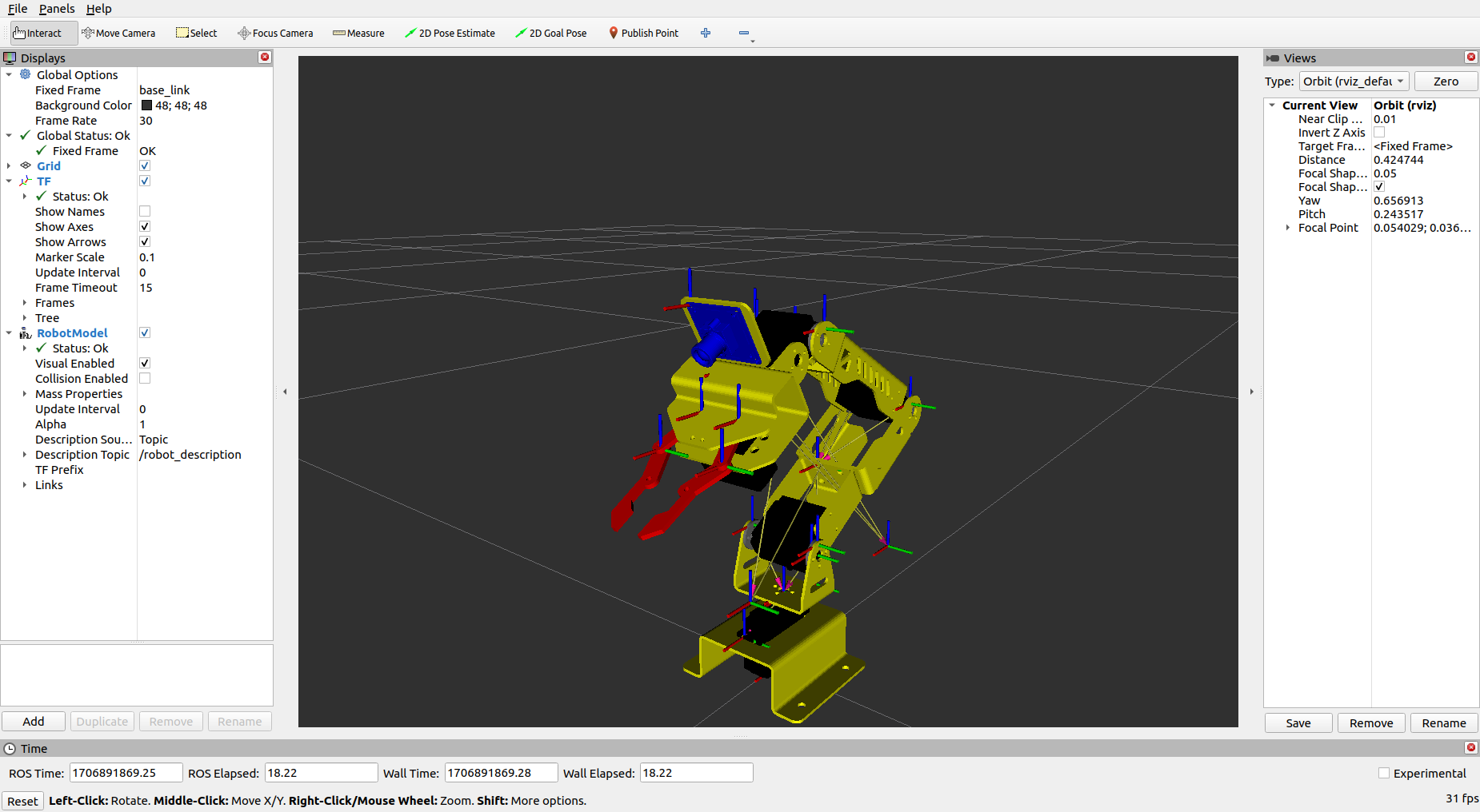
The Robotic is simulated to follow a user specific trajectory in order to reach the goal point in ROS2 based simulator called as the MoveIt.
MoveIt internally uses the concepts of Transforms and Inverse Kinematics between various arm componentsthus helps in providing accurate position of each of the arm w.r.t. other arm and to accurately estimate the Robotic Arm pose in 3D space.
The below shows the directory structure for the new workspace called as arduinobot_ws created as follows :
.
├── arduinobot_controller
│   ├── config
│   ├── include
│   │   └── arduinobot_controller
│   ├── launch
│   └── src
├── arduinobot_cpp_examples
│   └── src
├── arduinobot_description
│   ├── launch
│   ├── meshes
│   ├── rviz
│   └── urdf
├── arduinobot_moveit
│   ├── config
│   ├── include
│   │   └── arduinobot_moveit
│   ├── launch
│   └── src
├── arduinobot_msgs
│   ├── action
│   ├── include
│   │   └── arduinobot_msgs
│   ├── src
│   └── srv
├── arduinobot_py_examples
│   ├── arduinobot_py_examples
│   ├── resource
│   └── test
└── arduinobot_utils
    ├── arduinobot_utils
    ├── include
    │   └── arduinobot_utils
    └── src
Link to download the zip folder : https://drive.google.com/file/d/11jTPAgCkLsDxy1dmWzSqb4C-YJJF7PQV/view?usp=sharing
- The important packages that we are concerned about are the arduinobot_description, arduinobot_controller, arduinobot_moveit and arduinobot_cpp_examples.
- All the code files required for the smooth simulation and testing resides in these folders.
- First we launch the arduinobot_description file so that we could view our robotic arm in Gazebo environment. The command to launch it is as follows :
ros2 launch arduinobot_description gazebo.launch.py
- We then launch the controller file to ensure appropriate initial torques to all the joints of the Robotic Arm. Enter the following command :
ros2 launch arduinobot_controller controller.launch.py
- Once the initial setup is up running, we can then lastly launch the moveit configuration file using the below mentioned command :
ros2 launch arduinobot_moveit moveit.launch.py
- The Robotic arm can then be instructed to follow a specific path as decided by the User. Some of these goal angles and co-ordinates in 3D space are already given in the code under the cpp_examples and the simple moveit interface. Enter the command below.
ros2 run arduinobot_cpp_examples simple_moveit_interface
With this acheived so far we have now completed with our simulation and the robot is now ready to be used in a real environment after passing the checks from the simulator.
Simultaneous Localization and Mapping : SLAM Toolbox


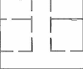
The SLAM Toolbox in ROS2 is a comprehensive suite of tools and libraries designed to facilitate Simultaneous Localization and Mapping (SLAM) for robotic systems. It encompasses various mapping algorithms, localization methods, sensor fusion techniques, feature extraction, and matching algorithms, as well as graph optimization functionalities. These components work together seamlessly within the ROS2 framework, enabling developers to build robust SLAM systems that allow robots to create and update maps of their environment while simultaneously estimating their own position within it. With visualization tools for debugging and analysis, the SLAM Toolbox empowers developers to deploy autonomous robots capable of navigating and understanding complex real-world environments effectively.
We have implemented the SLAM for our Robot in a simulated Gazebo World and have thus created a map useful for Localisation and Navigation. The following shows to create a map of the World in Gazebo:
- Launch our Gazebo World using the following command :
ros2 launch ros_robot_description gazebo.launch.py
- Next Launch our Robot Controller :
ros2 launch ros_robot_controller controller.launch.py
- Next you need to start the SLAMToolbox for creating the map :
ros2 launch slam_toolbox online_async_launch.py params_file:=/home/shubham/be_project_ws/src/ros_robot_controller/config/mapper_params_online_async.yaml use_sim_time:=true

# Replace the end of line of this with your path
- Atlast run the Joy node for PS4 Controller and you wouldbe able to move your Robot into the World and the MAP would be automatically be created :
ros2 run joy joy_node

ros2 launch ros_robot_controller joystick.launch.py
- After the MAP has been generated use the following command to save the generated SLAM Map :
ros2 run nav2_map_server map_saver_cli -f maps/my_map
The MAP has been created successfully using ROS2 SLAM Toolbox...!!!
Robot Navigation : ROS2 NAV2 Stack

In ROS2, the Navigation2 (Nav2) stack provides a powerful set of tools for autonomous navigation in robotic systems. Central to Nav2's capabilities are the global and local planners, which utilize costmaps to facilitate safe and efficient path planning. The global planner operates at a higher level, considering the entire environment to compute a path from the robot's current position to its destination. It utilizes data from various sensors, including LiDAR scans, to construct a global costmap that represents the traversability of different areas. On the other hand, the local planner focuses on short-term navigation decisions, taking into account the dynamic nature of the environment and the robot's immediate surroundings. It generates local costmaps based on real-time sensor data, such as LaserScan readings, to adaptively adjust the robot's trajectory and avoid obstacles. By integrating these components within the ROS2 ecosystem, developers can deploy autonomous robots capable of robust and reliable navigation in diverse environments, leveraging the rich functionality provided by Nav2 for global and local path planning, costmap management, and sensor data processing.
We run the following commands in order to start the nav2 stack and to make the Robot Navigate Autonomously throughout the MAP and the environment.
- Launch our Gazebo World using the following command :
ros2 launch ros_robot_description gazebo.launch.py
- Next Launch our Robot Controller :
ros2 launch ros_robot_controller controller.launch.py
- Atlast Launch this file to start your Navigation using the ROS2 NAV2 Stack :
ros2 launch nav2_bringup bringup_launch.py use_sim_time:=True map:=maps/my_world.yaml
We have now completed our Simulation Testing and we ar now good to go with Actual Hardware and Mechanical Assembly of your Robot!!!
Let's get some Hands on...!!!
Robot Locomotion : Assembly

We will now move on with the Mechanical Mountings and the Electronics Assembly. The following go through the sequence wise steps to be taken while the Hardware Implementation of the Robot…
Motors Mounting

.jpeg)
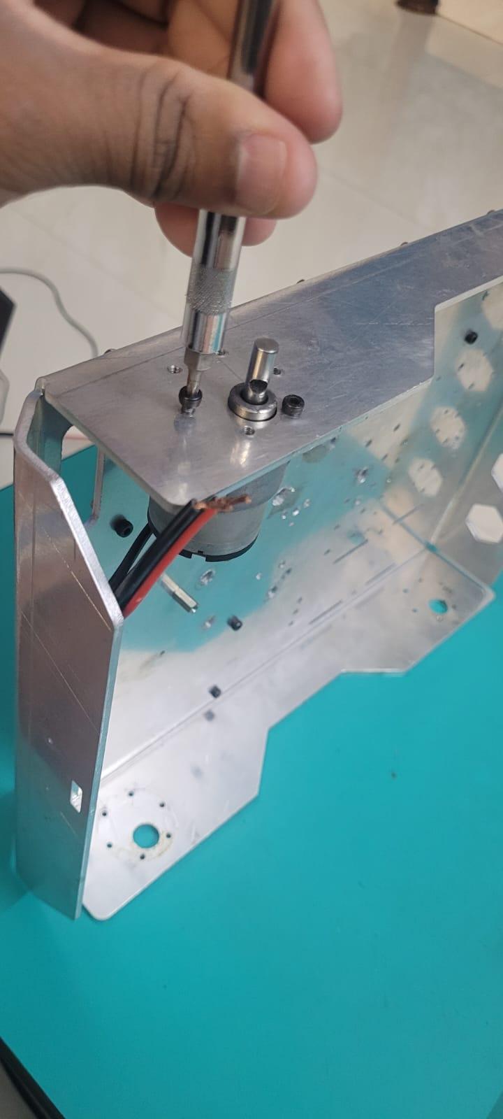
- Mount the Four Motors as shown in the figure to the Robot Chassis.
- Use M3 Alan Bolts (5mm depth) to rigidly fix the motors to the Chassis.
- Route the wires accordingly.
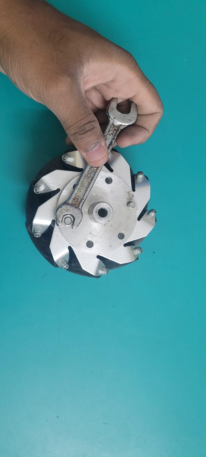
Wheel and Coupling Assembly

.jpeg)

- The Four couplings are needed to connect the Wheels with the Motor Shaft.
- Attach the Couplings to the wheels as shown above.
- Use M5 Alan Bolts and Nuts (60mm depth) to fix the couplings with the wheels.
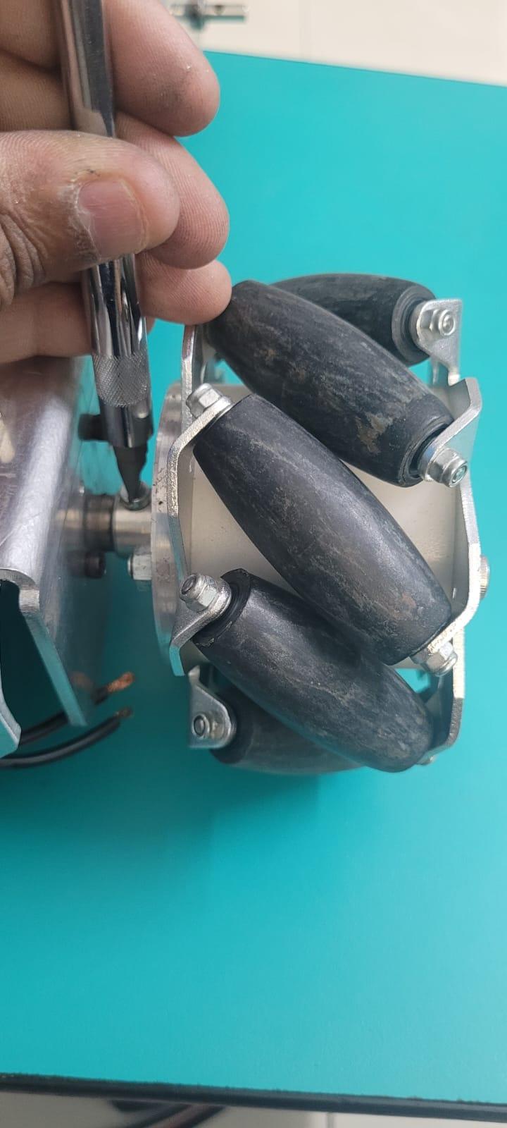
Attaching the Wheels

.jpeg)

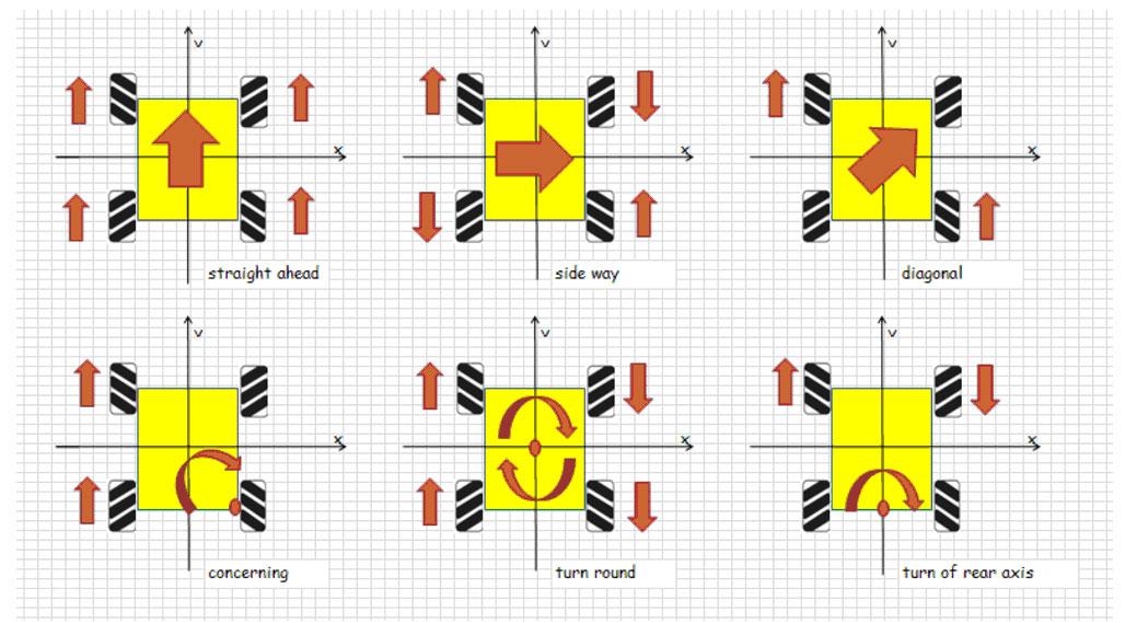
- Since this is a Four Wheel Mecanum Drive care must be taken such that the wheels should be fixed as shown in the first figure.
- Fix the wheels with the coupling to the motor shaft by using M4 Bolts.
Cytron Driver Mounting

.jpeg)

- Mount the Cytrons for both for the Motors.
- We have used M3 Alan Bolts for the mounting of the drivers using the M3 Spacers.
Base Servo Mechanism Mounting

.jpeg)

.jpeg)
.jpeg)
.jpeg)
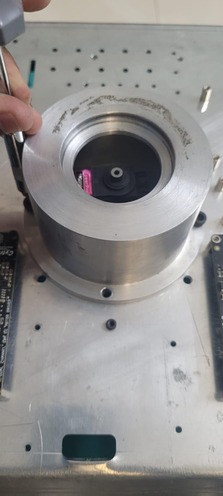
- This mechanism consists of the Lathe Part for Base servo and a Ball Bearing for smooth rotation of the above payload.
- The Rotating servo is enclosed inside the Lathe Part.
- The Rotating part is fixed precisely above the enclosed servo.
Buck Converter Mounting


- The Buck Converter is mounted below the Chassis.
- The wires are taken above to provide power to the Raspberry Pi.
ESP32 Mounting
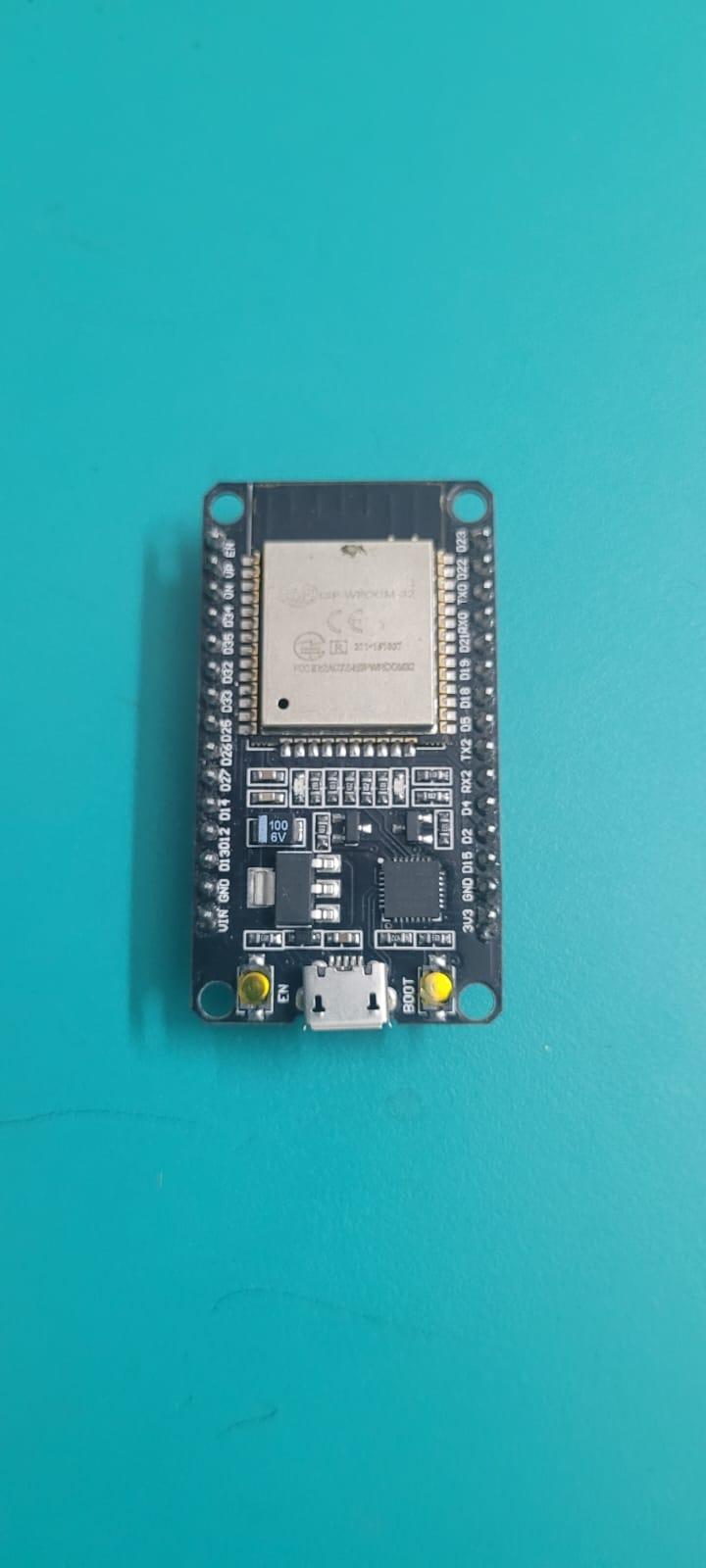
.jpeg)
- The ESP32 is mounted on top of the Chassis upside down so as to ease in connections.
- It is powered using a USB cable from Raspberry Pi.
Raspberry Pi Mounting
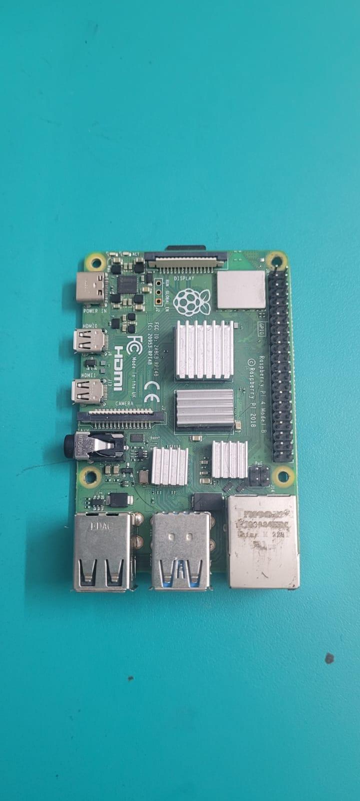
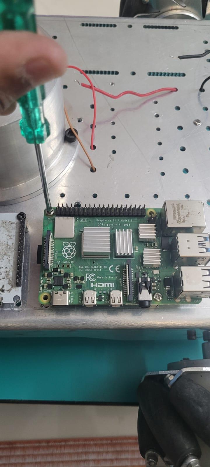.jpeg)
- The main microcontroller is mounted at the most optimised position such that all wires reach there in the most easiest manner possible.
- It is mounted on M3 spacers.
Servo HAT Mounting

- The Servo HAT is mounted below the Chassis.
- All servo connections are taken at the bottom face of the Chassis.
MPU6050 Mounting


The MPU is mounted in the center of the Chassis below the Chassis Plane
TF-Luna Mounting
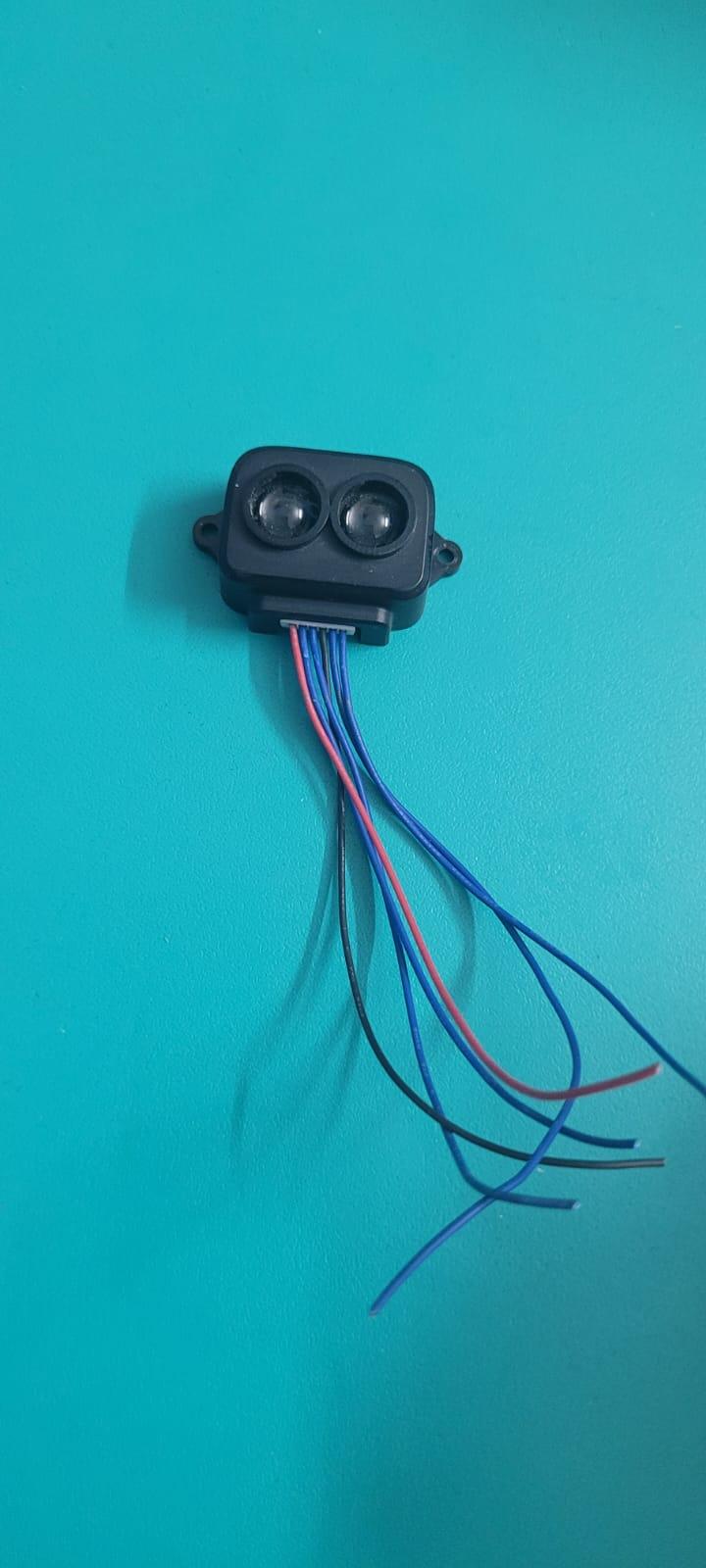

- TF-Luna sensor is mounted using M2 Bolts and Nuts.
- It is mounted at a considerably lower level to detect low lying objects.
Mouse Holder Mounting


.jpeg)
- The mouse is mounted for taking Robot Odometry Data.
- It is mounted below the Chassis using 3D printed parts such that the base of the mouse is in continuous contact with the Floor below when the Robot Locomotes.
Robotic Arm : Assembly

The Following depicts steps to be followed for assembling the Robotic Arm...
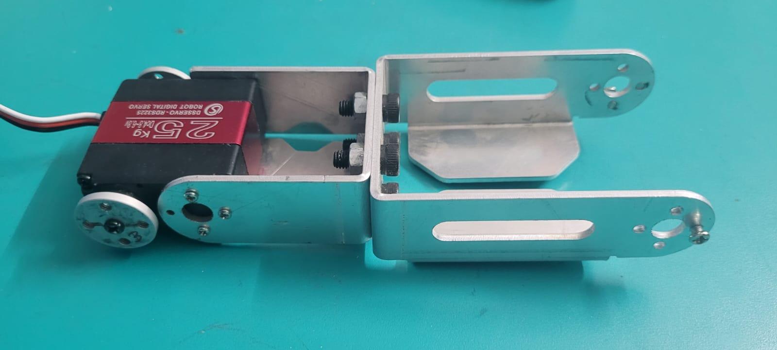
Base Servo Assembly

.jpeg)
- Attach the Base Servo with the Laser Cuts provided.
- Fix the servo with one side being the servo shaft and the other an idle horn for rotation.
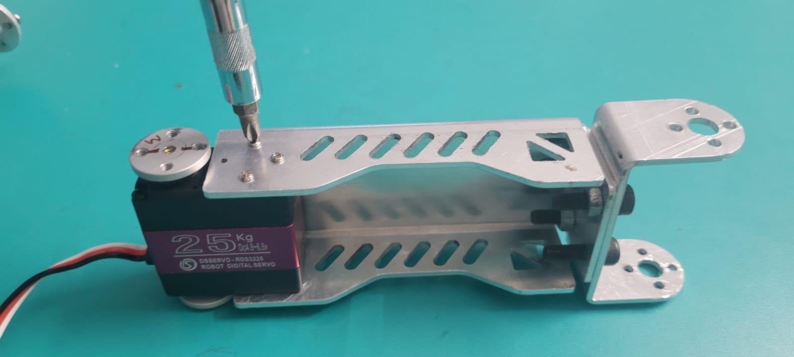
Middle Servo Assembly

.jpeg)
.jpeg)

Assemle the middle arm servo of the Robotic Arm as shown in the figure above.
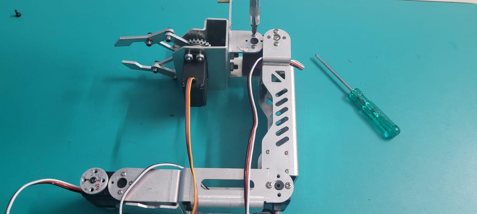
Upper Servo Assembly
.jpeg)

Attach the above servo as shown in the figure above.
Gripper Assembly

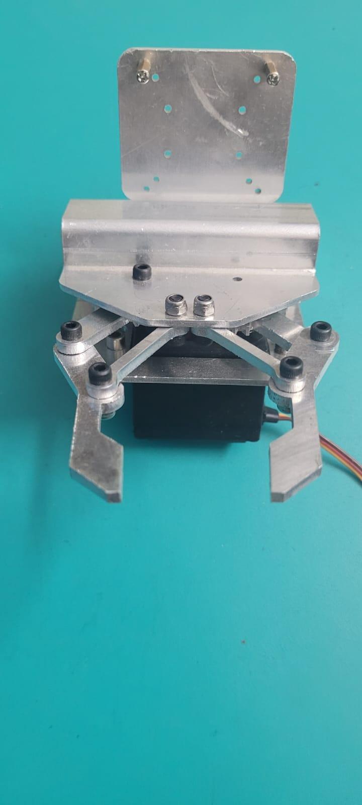
- The Gripper consists of the components like - Camera Mount, Gripper Servo and Gripper Linkages.
- The Gripper linkages are made using Laser Cutting (3mm thickness) .
- THe Gripper assemblt is then attached to the upper servo.
LIDAR Mounting
.jpeg)

- The Lidar is mounted on the forefront of the Chassis in order to get a clear view of the Environment and for ease in Data Visualization.
- We use 2.5mm Bolts for Lidar Mounts and connect it with Raspberry Pi with a USB Cable for Power and Data transfer.
Camera Mounting
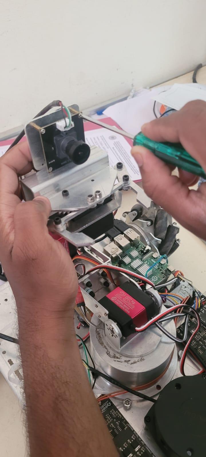
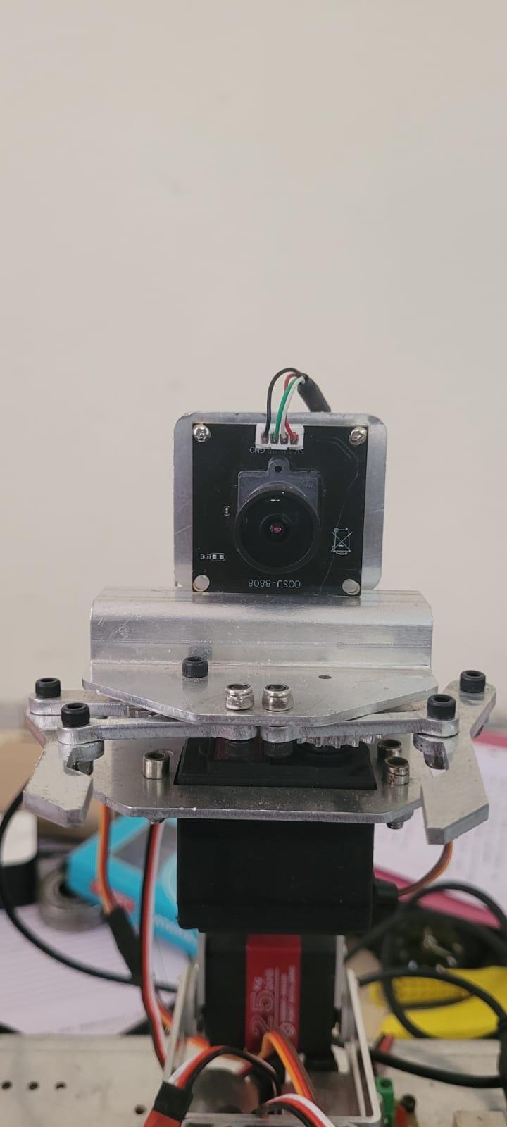
- The Camera Module is mounted on the top of the Robotic Arm so as to have a greater View for Camera Feed Angle.
- The camera is mounted using 2mm Spacers.
Robot Assembled...!!!

Finally the Robot is Mechanically Assembled and is now ready to make the Electronics Connections...!!!
Electronics Setup and Connections

The above circuit diagram for the whole Robot is been created using Autodesk EAGLE PCB Design software. It shows all the connections of all the electronic components to be connected.
The above schematic includes components such as Raspberry Pi micro-controller (Main MC) and the ESP32 Micro-controller acts a slave for the raspberry pi to receive locomotion motor signals and to actuate them accordingly.
The main reason to use ESP32 is that the robot has 4 wheels to drive and thus 4 PWM signals are required to maneuver the robot. Since, Raspberry Pi only has 2 PWM pins we are using ESP32 which is capable of providing 4 PWM pins and the communication between these two micro-controllers is initiated using USB Serial.
Also we have used a 16-channel Servo HAT for Raspberry Pi due the current and power requirements of the servo as well as the availability of PWM pins. The HAT commmunicates with the Raspberry Pi using the I2C Protocol.
A buck converter is used to power the Raspberry Pi from 12V to 5V Output.
The following steps depict the connection diagram for each part :
Power Distribution Board Schematic

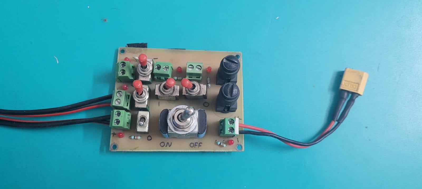
The above is a schematic for a Power Distribution to equally divide the 12V battery rails into 4 Rails of 12V each .
- First Rail goes towards Cytron1
- Second Rail goes towards Cytron2
- Third Rail for Buck Converter
- Fourth Rail for Servo HAT
The above board also consists of various switches to each rail so as to control them individually and to also have an isolation between also circuits and to provide ease in debugging. Each Rail aslo consists of a Fuse of 10A in order to protect the circuit from current spikes. LED's are used for ON/OFF indication of each power rail.
Raspberry Pi Pinout

Note : Refer the above Raspberry Pi Pinout while making the Connections
ESP32 Pinout

Note : Refer the above ESP32 Pinout while making the Connections
Motors Interfacing

- The above schematic shows the interfacing diagram for the four 12V DC motors controlled using the MDD10A dual channel Cytron motor driver and the microcontroller used is ESP32.
- The ESP32 is directly powered from the Raspberry Pi via the Serial USB Cable, whereas the two Cytron motor drivers are powered by the 12V rails from the power distribution board.
Connections :
Cytron 1 ----------------------- ESP32
DIR1 --------------------------> GPIO23
PWM1 -----------------------> GPIO22
DIR2 -------------------------> GPIO17
PWM2 -----------------------> GPIO16
Cytron 2 ----------------------- ESP32
DIR1 --------------------------> GPIO21
PWM1 ------------------------> GPIO19
DIR2 --------------------------> GPIO12
PWM2 ------------------------> GPIO13
Raspberry Pi - ESP32 Interfacing

The ESP32 and Raspberry Pi micro-controller has UART Serial Communication between them, and the ESP32 acts a slave and continuously receives serial commands from the Raspberry Pi over the Serial Bridge at a Baud Rate of 115200.
Connections :
Raspberry Pi ----------------------------------- ESP32
GPIO 14 (TXD) --------------------------> GPIO 16 (RXD)
GPIO 15 (RXD) --------------------------> GPIO 17 (TXD)
Raspberry Pi - Buck Converter Interfacing
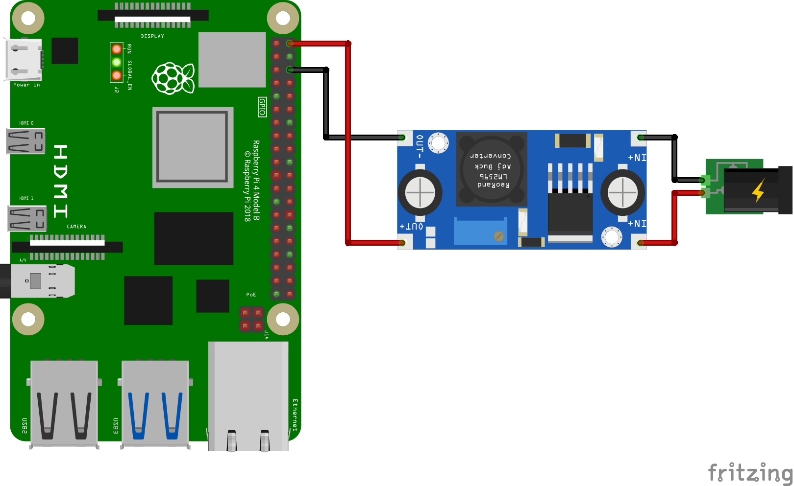
As Raspberry Pi Operates on 5V input we require a voltage stepping down component such as the Buck converter to step down the voltage from 12V to 5V.
Adjust the output of the Buck Converter to 5V by accurately rotating the potentiometer knob to provide a fixed 5V output at the output of the buck converter.
Note : Verify the buck converter output to 5V before connecting it to the Raspberry Pi
Connections :
Buck Converter ---------------------- Raspberry Pi
Input (+) -------------------------------------> 12V
Input (-) --------------------------------------> GND
Output (+) --> 5V -------------------------> 5V Power
Output (-) --> GND -----------------------> GND
Servo-hAT Interfacing

The above used is a Servo HAT used for driving the Five Servo Motors by Interfacing it with the Raspberry Pi microcontroller and the communication between them is acheived by using I2C protocol.
Waveshare Servo HAT :
Needless to say, the Raspberry Pi is powerful enough in most cases, yet it's not that good at providing precise PWM output. You may have tried to control a robotic arm or a hexapod walker by using the Pi, but finally get frustrated due to the limited number of PWM outputs and the jittering servo.
Features:
- Standard Raspberry Pi 40PIN GPIO extension header, supports Raspberry Pi series boards, Jetson Nano
- I2C controlled, using only 2 pins
- Up to 16-Channel servo/PWM outputs, 12-bit resolution for each channel (4096 scales)
- Integrates 5V regulator, up to 3A output current, can be powered from battery through VIN terminal
- Standard servo interface, supports common used servos
- Reserved I2C control pins, allows to work with other control boards
- Comes with development resources and manual (examples in python like Bluetooth/WiFi remote control)
Specifications :
- Power supply: 5V (Pi connector) OR 6V~12V (VIN terminal)
- Servo voltage: 5V
- Logic voltage: 3.3V
- Driver: PCA9685
- Control interface: I2C
- Dimension: 65mm x 30mm
- Mounting hole size: 3.0mm
Due to these advantages we opt for using a Servo Hat :)
Connections :
Raspberry Pi ---------------------- Servo HAT
GPIO 2 (SDA) ------------------------> SDA
GPIO 3 (SCL) ------------------------> SCL
Servo HAT ---------------------- Servos
Channel 2 --------------------------> Base Servo (1)
Channel 5 --------------------------> Middle Servo (2)
Channel 7 --------------------------> Upper Servo (3)
Channel 11 --------------------------> Gripper Servo (4)
Channel 14 --------------------------> Base Rotate Servo (5)
MPU6050 Interfacing

The MPU6050 with Accelerometer and Gyroscope is used to get accurate accurate Yaw movement of the robot about the Z-axis and to fuse this data with the data coming from Mouse Odometry.
Connections :
Raspberry Pi ---------------------- MPU6050
5V Power -----------------------------> 5V
GND -----------------------------------> GND
GPIO 2 (SDA) -----------------------> SDA
GPIO 3 (SCL) -----------------------> SCL
TF Luna - Raspberry Pi Interfacing
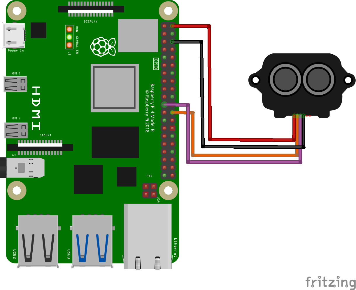
TF-Luna acts a secondary sensor to get the obtacle distance and to avoid robot from collision with it if the Obstacle height lies below the LIDAR Range of Influence. The Interfacing is done Serial UART.
Connections :
Raspberry Pi ----------------------- TF-Luna
5V Power -------------------------------> 5V
GND -------------------------------------> GND
GPIO 8 (TXD4) -----------------------> RXD
GPIO 9 (RXD4) -----------------------> TXD
USB Connections to Raspberry Pi

Raspberry Pi Offers us with 4 USB ports to connect any peripherals we need to connect. We will be using all of these available ports in order to carry our our desired activities and tasks targeted....
- Connect LIDAR USB Cable to 1st Port.
- Connect ESP Data USB Cable to 2nd Port.
- Connect Camera USB Cable to 3rd Port.
- Connect Wireless Mouse Receiver to 4th Port.
Connections :
Component ---------------------- Raspberry Pi
LIDAR -----------------------------> USB PORT 0
ESP32 ----------------------------> USB PORT 1
Camera Module ----------------> USB PORT 2
Mouse Receiver ----------------> USB PORT 3
Note : Follow this order while making connections in order to avoid any USB PORT mismatch.
Powering Up the Robot


Let's now see how to start our Robot prior every run...
- Connect the 12V Li-Po Battery to the Input of the Power Distribution Board (PDB) and turn on the main power swtich of the PDB.
- After this turn on the two switches connected to the two Cytron motor drivers. This will power up the Motor drivers and it will make the locomotion of the robot powered.
- Now turn on the Buck Converter power supply switch. This will turn on the Raspberry Pi connected via the Buck Converter. This will boot up your Raspberry Pi.
- Atlast turn on the switch for the Servo Hat which will power all the servos connected to the Robotic Arm.
This will provide power to all components on the Robot and now the Robot is ready for functioning....!!!
Let's Start to Code

After the mechanical assembly and the appropriate electronic connections we atlast move on to our last part of the project which is writing the code to make our robot function according to out desire and to acheive the target applications.
Scripts for Robot Functioning :
- ESP32 Locomotion code.
- ROS2 PS4 UART code for interface between Raspberry Pi and ESP32.
- PS4 Robotic Arm Control Code.
- Inverse Kinematics code for Robotic Arm Trajectory Planning.
- Aruco Marker Detection Code to detect Aruco Marker ID's and display it using Flask Website and AJAX for relatime data upload.
Launch Files and Node to be run :
- Launch File to run the Camera Node.
- Launch File to run the LIDAR Node.
- To run the Joy Node in order to receive PS4 Data.
ESP32 Locomotion Code
.gif)
The Locomotion code is dumped on the ESP32 using the Arduino IDE. It is a C++ code used for ESP32 which receives the PS4 data from Raspberry Pi via Serial Communication and thus further controls the PWM and direction pins ofeach motor and actuates them based on a Kinematical Equation for a Four Wheel Mecanum Drive.
The Following is the Code for ESP32 Locomotion :
//Locomotion pins
#define loco_dir1_pin 23
#define loco_pwm1_pin 22
#define loco_dir2_pin 17
#define loco_pwm2_pin 16
#define loco_dir3_pin 21
#define loco_pwm3_pin 19
#define loco_dir4_pin 12
#define loco_pwm4_pin 13

//locomotion
int M1_pwm = 0;
byte M1_dir = 0;
int M2_pwm = 0;
byte M2_dir = 0;
int M3_pwm = 0;
byte M3_dir = 0;
int M4_pwm = 0;
byte M4_dir = 0;
int toggle_mode = 0;

//PS4
float Right_X = 0;
float Right_Y = 0;
float Left_X = 0;

void setup() {
  // put your setup code here, to run once:
  Serial.begin(115200);

  //locomotion setup
  ledcSetup(0, 8000, 8);
  ledcSetup(1, 8000, 8);
  ledcSetup(2, 8000, 8);
  ledcSetup(3, 8000, 8);

  ledcAttachPin(loco_pwm1_pin, 0);
  ledcAttachPin(loco_pwm2_pin, 1);
  ledcAttachPin(loco_pwm3_pin, 2);
  ledcAttachPin(loco_pwm4_pin, 3);

  pinMode(loco_dir1_pin, OUTPUT);
  pinMode(loco_dir2_pin, OUTPUT);
  pinMode(loco_dir3_pin, OUTPUT);
  pinMode(loco_dir4_pin, OUTPUT);
}

void loop() {

  if (Serial.available() >= sizeof(float) * 3) {

    float received_values[3];
    Serial.readBytes((char *)received_values, sizeof(float) * 3);

    // Print the received values
    Right_Y = received_values[0];
    Right_X = received_values[1];
    Left_X = received_values[2];

    calculate();
    drive();
  }
  else {
    //locomotion
    M1_pwm = 0;
    M2_pwm = 0;
    M3_pwm = 0;
    M4_pwm = 0;
  }
}

void calculate() {
  //locomotion
   // mapped left_y joystick for translation and right_x for rotation - linear mapping
  //both sticks can be used simultaneously
  M1_pwm = (Right_Y - Right_X + Left_X);
  M2_pwm = (Right_Y + Right_X - Left_X);
  M3_pwm = (Right_Y + Right_X + Left_X);
  M4_pwm = (Right_Y - Right_X - Left_X);

  //direction deduction from mapped pwm values
  //dir = 0 bot moves forward
  if (M1_pwm > 0) {
    M1_dir = 0;
  } else {
    M1_dir = 1;
    M1_pwm = abs(M1_pwm);
  }

  if (M2_pwm > 0) {
    M2_dir = 0;
  } else {
    M2_dir = 1;
    M2_pwm = abs(M2_pwm);
  }

  if (M3_pwm > 0) {
    M3_dir = 0;
  } else {
    M3_dir = 1;
    M3_pwm = abs(M3_pwm);
  }

  if (M4_pwm > 0) {
    M4_dir = 0;
  } else {
    M4_dir = 1;
    M4_pwm = abs(M4_pwm);
  }
  M1_pwm = constrain(M1_pwm, 0, 255);
  M2_pwm = constrain(M2_pwm, 0, 255);
  M3_pwm = constrain(M3_pwm, 0, 255);
  M4_pwm = constrain(M4_pwm, 0, 255);
}

void drive() {
  //locomotion
   //at dir = 0 bot moves forward
  digitalWrite(loco_dir1_pin, M1_dir);
  ledcWrite(0, M1_pwm);

  digitalWrite(loco_dir2_pin, M2_dir);
  ledcWrite(1, M2_pwm);

  digitalWrite(loco_dir3_pin, M3_dir);
  ledcWrite(2, M3_pwm);

  digitalWrite(loco_dir4_pin, M4_dir);
  ledcWrite(3, M4_pwm);

  Serial.print(M1_pwm) ;
  Serial.print("\t") ;
  Serial.print(M1_dir) ;
  Serial.print("\t") ;
  Serial.print(M2_pwm) ;
  Serial.print("\t") ;
  Serial.print(M2_dir) ;
  Serial.print("\t") ;
  Serial.print(M3_pwm) ;
  Serial.print("\t") ;
  Serial.print(M3_dir) ;
  Serial.print("\t") ;
  Serial.print(M4_pwm) ;
  Serial.print("\t") ;
  Serial.print(M4_dir) ;
  Serial.println("\t") ;
}
The PS4 is connected to the Raspberry Pi via Bluetooth and publishes its messages on a ROS2 topic Joy. The script thus subscribes from this topic and thus sends the data via the Serial USB to the ESP32 for Locomotion Control.
The following is the Code for ESP32 and Raspberry Pi Interfacing :
import rclpy
from rclpy.node import Node
from sensor_msgs.msg import Joy

import serial
import time
import struct

ser = serial.Serial('/dev/ttyUSB1', 115200, timeout=1)

class LocControl(Node):
    def __init__(self):
        super().__init__("loc_control")
        self.joy_sub = self.create_subscription(Joy, 'joy', self.joy_callback, 10)

    def ps4_deadband(self, ps4_value):
        if((ps4_value < 5) and (ps4_value > -5)):
            ps4_value = 0
        return ps4_value

    def send_data(self, values):
        data = struct.pack('fff', *values)
        ser.write(data)

    def joy_callback(self, msg:Joy):
        Right_Y = self.ps4_deadband(msg.axes[4] * 255)
        Right_X = self.ps4_deadband(msg.axes[3] * 255)
        Left_X = self.ps4_deadband(msg.axes[0] * 255)

        floats = [Right_Y, Right_X, Left_X]

        self.send_data(floats)
        print(ser.readline().decode().strip())

def main():
    rclpy.init()
    loc_control = LocControl()
    rclpy.spin(loc_control)
    loc_control.destroy_node()
    rclpy.shutdown()


if __name__ == '__main__':
    main()
PS4 Controlled Robotic Arm Code
This script ensures the Controlling and actuation of each Robotic Arm Servo by sending commands using PS4 controller. We have used Servo HAT for Raspberry Pi and have used the PCA9685 library from Adafruit to establish a I2C connection between the HAT and our microcontroller.
We have used 5 channels for 5 servos from among the 16 channels availble on the HAT. The code utlises this information to actuate the correct servo at the correct time.
The Servo Control Code is as follows :
import rclpy
from rclpy.node import Node
from sensor_msgs.msg import Joy

from adafruit_servokit import ServoKit
kit = ServoKit(channels=16)
servo = 16

class ServoControl(Node):
    def __init__(self):
        super().__init__("servo_control")
        self.base_angle = 165
        self.mid_angle = 180
        self.upp_angle = 180
        self.grip_angle = 80
        self.rotate_angle = 40

        kit.servo[2].angle = int(self.base_angle)
        kit.servo[5].angle = int(self.mid_angle)
        kit.servo[8].angle = int(self.upp_angle)
        kit.servo[11].angle = int(self.grip_angle)
        kit.servo[14].angle = int(self.rotate_angle)

        self.joy_sub = self.create_subscription(Joy, 'joy', self.joy_callback, 10)

    def drive_base_servo(self, base_pos, base_neg):
        if(base_pos==1):
            self.base_angle = self.base_angle+5
            if (self.base_angle >= 165):
                self.base_angle = 165
                kit.servo[2].angle=int(self.base_angle)
            else:
                kit.servo[2].angle=int(self.base_angle)
        if(base_neg==1):
            self.base_angle = self.base_angle-5
            if (self.base_angle <= 0):
                self.base_angle = 0
                kit.servo[2].angle=int(self.base_angle)
            else:
                kit.servo[2].angle=int(self.base_angle)

    def drive_mid_servo(self, mid_pos, mid_neg):
        if(mid_pos==1):
            self.mid_angle = self.mid_angle+5
            if (self.mid_angle >= 180):
                self.mid_angle = 180
                kit.servo[5].angle=int(self.mid_angle)
            else:
                kit.servo[5].angle=int(self.mid_angle)
        if(mid_neg==1):
            self.mid_angle = self.mid_angle-5
            if (self.mid_angle <= 60):
                self.mid_angle = 60
                kit.servo[5].angle=int(self.mid_angle)
            else:
                kit.servo[5].angle=int(self.mid_angle)

    def drive_upp_servo(self, upp_pos, upp_neg):
        if(upp_pos==1):
            self.upp_angle = self.upp_angle+5
            if (self.upp_angle >= 180):
                self.upp_angle = 180
                kit.servo[8].angle=int(self.upp_angle)
            else:
                kit.servo[8].angle=int(self.upp_angle)
        if(upp_neg==1):
            self.upp_angle = self.upp_angle-5
            if (self.upp_angle <= 100):
                self.upp_angle = 100
                kit.servo[8].angle=int(self.upp_angle)
            else:
                kit.servo[8].angle=int(self.upp_angle)

    def grip_servo(self, grip):
        if(grip==1):
            self.grip_angle = self.grip_angle+5
            if (self.grip_angle >= 80):
                self.grip_angle = 80
                kit.servo[11].angle=int(self.grip_angle)
            else:
                kit.servo[11].angle=int(self.grip_angle)
        if(grip==(-1)):
            self.grip_angle = self.grip_angle-5
            if (self.grip_angle <= 0):
                self.grip_angle = 0
                kit.servo[11].angle=int(self.grip_angle)
            else:
                kit.servo[11].angle=int(self.grip_angle)

    def rotate_servo(self, rotate):
        if(rotate==1):
            self.rotate_angle = self.rotate_angle+5
            if (self.rotate_angle >= 180):
                self.rotate_angle = 180
                kit.servo[14].angle=int(self.rotate_angle)
            else:
                kit.servo[14].angle=int(self.rotate_angle)
        if(rotate==(-1)):
            self.rotate_angle = self.rotate_angle-5
            if (self.rotate_angle <= 0):
                self.rotate_angle = 0
                kit.servo[14].angle=int(self.rotate_angle)
            else:
                kit.servo[14].angle=int(self.rotate_angle)

    def ps4_deadband(self, ps4_value):
        if((ps4_value < 5) and (ps4_value > -5)):
            ps4_value = 0
        return ps4_value

    def joy_callback(self, msg:Joy):
        # Extract values from joystick
        base_pos = int(msg.buttons[2])
        base_neg = int(msg.buttons[0])

        mid_pos = int(msg.buttons[3])
        mid_neg = int(msg.buttons[1])

        upp_pos = int(msg.buttons[5])
        upp_neg = int(msg.buttons[4])

        grip = int(msg.axes[7])

        rotate = int(msg.axes[6])

        self.drive_base_servo(base_pos, base_neg)
        self.drive_mid_servo(mid_pos, mid_neg)
        self.drive_upp_servo(upp_pos, upp_neg)
        self.grip_servo(grip)
        self.rotate_servo(rotate)

        print(self.base_angle, self.mid_angle,
              self.upp_angle, self.grip_angle,
              self.rotate_angle)

def main():
    rclpy.init()
    servo_control = ServoControl()
    rclpy.spin(servo_control)
    servo_control.destroy_node()
    rclpy.shutdown()

if __name__ == '__main__':
    main()
Note : Before running this code your PS4 must be connected and the Joy node must be running in order to receive the actuation commands. Also ensure that your I2C communication is initiated and is running properly.
Downloads
Inverse Kinematics for Robotic Arm
This Python code establishes a ROS (Robot Operating System) node for controlling servos in a robotic arm. The ServoControl class inherits from rclpy.node.Node to manage servo movements based on specified goals. The initial positions of the servos are set, and there are methods to calculate the angles required to reach a specific position `goal_to_reach`. The actuate_servos method moves the servos gradually to reach the desired angles, ensuring smooth motion. Additionally, there are functions for controlling the gripper `gripper_grab`, `gripper_release` and adjusting the wrist angle `wrist_down`, `wrist_up`.
The main function initializes ROS, creates an instance of ServoControl, calculates the angles to reach a specific goal position, moves the servos accordingly, performs gripping actions, adjusts the wrist position, and then spins the node to handle ROS communication. Finally, it cleans up by destroying the node and shutting down ROS. This code provides a structured approach to controlling the movements of a robotic arm, facilitating tasks such as reaching, gripping, and releasing objects in a robotic manipulation scenario.
The Inverse Kinematics Code for Robotic Arm Trajectory :
import rclpy
from rclpy.node import Node
import math
import time

from adafruit_servokit import ServoKit
kit = ServoKit(channels=16)
servo = 16

class ServoControl(Node):
    def __init__(self):
        super().__init__("servo_control")
        self.initial_base = 65
        self.initial_a1 = 165
        self.initial_a2 = 180
        self.upp_angle = 85
        self.grip_angle = 100

        kit.servo[14].angle = int(self.initial_base)
        kit.servo[8].angle = int(self.initial_a1)
        kit.servo[2].angle = int(self.initial_a2)
        kit.servo[5].angle = int(self.upp_angle)
        kit.servo[11].angle = int(self.grip_angle)

        time.sleep(3)

    def goal_to_reach(self, x, y, z):
        base = math.degrees(math.atan2(y,x))

        l = math.sqrt(pow(x,2) + pow(y,2))

        phi = math.degrees(math.atan2(z,l))

        h = math.sqrt(pow(l,2) + pow(z,2))

        theta = math.degrees(math.acos((h/2)/140))

        final_a1 = phi + theta
        final_a2 = phi - theta
        final_base = 90 + base

        final_a1 = int(final_a1)
        final_a2 = int(120 - final_a2)
        final_base = int(final_base)

        print("final_angles")
        print(final_base, final_a1, final_a2)
        return final_base, final_a1, final_a2

    def actuate_servos(self, final_base, final_a1, final_a2):
        if(self.initial_base < final_base):
            for i in range(self.initial_base, final_base+1, 1):
                kit.servo[14].angle = int(i)

        elif(self.initial_base > final_base):
            for i in range(self.initial_base, final_base-1, -1):
                kit.servo[14].angle = int(i)

        if (self.initial_a1 > final_a1):
            for i in range(self.initial_a1, final_a1-1, -1):
                kit.servo[2].angle = int(i)

        if (self.initial_a2 > final_a2):
            for i in range(self.initial_a2, final_a2-1, -1):
                kit.servo[5].angle = int(i)

    def gripper_grab(self):
        for i in range(self.grip_angle, -1, -1):
                print(i)
                kit.servo[11].angle = int(i)

    def gripper_release(self):
        for i in range(0, self.grip_angle+1, 1):
                print(i)
                kit.servo[11].angle = int(i)

    def wrist_down(self):
        for i in range(self.upp_angle, -1, -1):
                print(i)
                kit.servo[8].angle = int(i)

    def wrist_up(self):
        for i in range(0, self.upp_angle, 1):
                print(i)
                kit.servo[8].angle = int(i)

def main():
    rclpy.init()
    servo_control = ServoControl()
    final_base , final_a1 , final_a2 = servo_control.goal_to_reach(100,100,50)
    servo_control.actuate_servos(final_base, final_a1 , final_a2)
    time.sleep(2)
    servo_control.gripper_grab()
    time.sleep(2)
    servo_control.wrist_down()
    time.sleep(3)
    servo_control.wrist_up()
    time.sleep(3)
    rclpy.spin(servo_control)
    servo_control.destroy_node()
    rclpy.shutdown()

if __name__ == '__main__':
    main()
Note : Remember to change the servo limiting values (max. and min.) depending upon the Servo Angles at which you have mounted your servos and its rest angle.
Downloads
Aruco-Marker Detection and Website Display


The code sets up a ROS (Robot Operating System) node for detecting ArUco markers from an image stream coming from a camera. It uses OpenCV for image processing and ArUco marker detection. The ArUcoDetector class initializes a ROS node named aruco_detect and subscribes to the /camera1/image_raw topic to receive image messages. Upon receiving an image, it converts it from ROS format to OpenCV format and detects ArUco markers using the detectMarkers function from the cv2.aruco module.
Detected marker IDs are stored in a set called detected_ids to keep track of which markers have been detected previously. The detected markers are drawn on the image using drawDetectedMarkers function from cv2.aruco. Additionally, a Flask web server is set up to serve a simple HTML interface at the root route (/) and provide an endpoint (/aruco_ids) to retrieve the IDs of the detected ArUco markers.
In the main function, the ROS node is initialized, and an instance of the ArUcoDetector class is created. Then, a Flask server is started in a separate thread to handle web requests while the ROS node continues to run in the main thread using rclpy.spin(aruco_detector). Once the ROS node is shut down, the Flask server thread is also terminated.
Overall, this code provides a framework for real-time ArUco marker detection and a simple web interface to display the detected marker IDs. It can be further extended to include additional functionalities like marker pose estimation, marker tracking, or integrating with other ROS nodes for robot control or navigation.
Code for Aruco Marker Detection and Realtime Data Display :
import rclpy
from rclpy.node import Node
from sensor_msgs.msg import Image
import cv2
from cv_bridge import CvBridge
import cv2.aruco as aruco
from flask import Flask, jsonify, render_template

app = Flask(__name__)

class ArUcoDetector(Node):
    def __init__(self):
        super().__init__('aruco_detect')
        self.subscription = self.create_subscription(Image, '/camera1/image_raw', self.image_callback, 10)
        self.cv_bridge = CvBridge()
        self.marker_size = 0.05  # Size of the ArUco marker in meters
        self.detected_ids = set()  # Set to store detected ArUco marker IDs

    def image_callback(self, msg):
        try:
            cv_image = self.cv_bridge.imgmsg_to_cv2(msg, desired_encoding='bgr8')
        except Exception as e:
            self.get_logger().error("Error converting ROS to CV Image: %s" % str(e))
            return

        # Detect ArUco markers
        dictionary = aruco.getPredefinedDictionary(aruco.DICT_4X4_50)  # You can change the dictionary and marker size as needed
        parameters = aruco.DetectorParameters()
        corners, ids, _ = aruco.detectMarkers(cv_image, dictionary, parameters=parameters)

        if ids is not None:
            new_ids = [id[0] for id in ids if id[0] not in self.detected_ids]
            for new_id in new_ids:
                print("Detected ArUco ID:", new_id)
                self.detected_ids.add(new_id)

            cv2.aruco.drawDetectedMarkers(cv_image, corners, ids)

        #cv2.imshow('output video', cv_image)
        cv2.waitKey(1)

@app.route('/')
def index():
    return render_template('index.html')

@app.route('/aruco_ids', methods=['GET'])
def get_aruco_ids():
    global aruco_detector
    ids = [int(id) for id in aruco_detector.detected_ids]  # Convert int32 IDs to Python integers
    return jsonify(ids)

def main(args=None):
    rclpy.init(args=args)

    global aruco_detector
    aruco_detector = ArUcoDetector()

    # Start Flask server in a separate thread
    import threading
    flask_thread = threading.Thread(target=lambda: app.run(host='0.0.0.0'))
    flask_thread.start()

    rclpy.spin(aruco_detector)

    aruco_detector.destroy_node()
    rclpy.shutdown()

if __name__ == '__main__':
    main()
Link to generate Aruco Markers : https://chev.me/arucogen/
Downloads
Mouse Interfacing for Robot Odometry
This Python script utilizes the `evdev` library to capture mouse events from a specified event file, typically associated with a USB mouse connected to the system. It begins by specifying the event file path, which needs to be adjusted to match the event number corresponding to the connected mouse device. Additionally, the script requires the CPI (Counts Per Inch) value of the mouse to calculate the conversion factor for translating mouse movement counts into centimeters.
Upon initialization, the script attempts to open the specified event file and handles any potential `FileNotFoundError` by notifying the user if the mouse is not found or if there's an issue with the event file. Following this, it calculates the conversion factor needed for translating mouse movement counts into centimeters based on the provided CPI.
The `parse_event` function is defined to interpret mouse events, particularly focusing on relative motion events (mouse movements). It extracts the relative X and Y motion values from the event and returns them.
The script then enters a loop to continuously read mouse events using `mouse.read_loop()`. Inside the loop, it parses each event, calculates the displacement in centimeters for both the X and Y axes, and prints out the updated displacement values. This loop continues indefinitely until interrupted by a `KeyboardInterrupt` (Ctrl+C), upon which it gracefully exits the program.
Overall, this script provides a simple yet effective way to monitor and quantify mouse movements in real-time, converting them into displacement values in centimeters for both horizontal and vertical axes. It could serve as a foundation for building various applications requiring real-time mouse tracking and analysis.
Code for Mouse Odometry :
from evdev import InputDevice, categorize, ecodes

# Find the event file corresponding to the USB mouse
event_file = '/dev/input/event1'  # Replace X with the event number of your mouse

# CPI of the mouse (replace this with the CPI of your mouse)
mouse_cpi = 1000

try:
    mouse = InputDevice(event_file)
except FileNotFoundError:
    print("Mouse not found. Make sure it's connected and check the event file.")
    exit()

# Calculate conversion factor from counts to centimeters
conversion_factor = (2.54 / mouse_cpi)*2

# Function to parse the event for mouse movements
def parse_event(event):
    if event.type == ecodes.EV_REL:
        # Check for relative motion events (mouse movements)
        if event.code == ecodes.REL_X:
            return event.value, 0
        elif event.code == ecodes.REL_Y:
            return 0, event.value
    return 0, 0

print("Reading mouse events. Press Ctrl+C to exit.")

try:
    x_displacement_cm = 0
    y_displacement_cm = 0

    for event in mouse.read_loop():
        x_delta, y_delta = parse_event(event)
        x_displacement_cm += x_delta * conversion_factor
        y_displacement_cm += y_delta * conversion_factor
        print(f"X displacement: {x_displacement_cm:.2f} cm, Y displacement: {y_displacement_cm:.2f} cm")

except KeyboardInterrupt:
    print("\nExiting...")
Note : Change the event name based on the mouse event on which your mouse is pushing the data.
Downloads
MPU6050 Interfacing for YAW Angle
This Python script interfaces with the MPU6050 accelerometer and gyroscope sensor via the I2C bus to measure the angle of rotation about the z-axis (yaw) in real-time. It begins by importing the necessary modules, including `smbus2` for I2C communication and `time` for time-related operations.
The script then defines the MPU6050 registers and addresses, along with the gyroscope sensitivity value, and initializes the I2C bus. It configures the MPU6050 by writing to the power management register to wake up the sensor.
Within the main loop, the script continuously reads the gyroscope data for the z-axis and calculates the angular velocity in degrees per second. It also tracks the change in time between readings to compute the change in angle. The change in angle is then accumulated to calculate the total angle moved in the z-axis (yaw).
The script includes a check to ensure that only significant changes in the z-axis angle are considered, with a threshold set at 0.01 degrees. If the change exceeds this threshold, it updates the total angle moved and prints the updated value.
The main loop is interrupted gracefully by a `KeyboardInterrupt` (Ctrl+C) to exit the program. Additionally, a small delay of 0.01 seconds is added to control the sampling rate of the sensor.
Overall, this script provides a basic implementation for real-time monitoring of yaw angle using the MPU6050 gyroscope, making it suitable for applications requiring simple orientation tracking, such as robotics, drone stabilization, or motion sensing systems.
Code for MPU6050 :
import smbus2
import time
import math

# MPU6050 registers and addresses
MPU6050_ADDR = 0x68
PWR_MGMT_1 = 0x6B
GYRO_ZOUT_H = 0x47

# Gyroscope sensitivity
GYRO_SENSITIVITY = 131.0  # degrees per second per LSB

# Initialize I2C bus
bus = smbus2.SMBus(1)

# Initialize MPU6050
bus.write_byte_data(MPU6050_ADDR, PWR_MGMT_1, 0)

# Initial time
prev_time = time.time()

# Initial z-axis angle
prev_angle_z = 0.0

# Total angle moved in z-axis
total_angle_z = 0.0

# Main loop
try:
    while True:
        # Read gyro data for z-axis
        gyro_z_raw = bus.read_byte_data(MPU6050_ADDR, GYRO_ZOUT_H)
        if gyro_z_raw > 127:
            gyro_z_raw -= 256  # Convert to signed value if necessary
        gyro_z = gyro_z_raw / GYRO_SENSITIVITY  # Convert to degrees per second

        # Current time
        curr_time = time.time()
        dt = curr_time - prev_time

        # Calculate angle moved in z-axis
        angle_z = gyro_z * dt  # Change in angle in this time step

        # Check if there's a significant change in the z-axis angle
        if abs(angle_z) > 0.01:  # Adjust this threshold as needed
            # Update total angle moved in z-axis
            total_angle_z += angle_z

            # Print angle moved in z-axis
            print("Angle moved in z-axis: {:.2f} degrees".format(total_angle_z))

        print(total_angle_z)

        # Update previous time for next iteration
        prev_time = curr_time

        # Add a delay to control the sampling rate
        time.sleep(0.01)

except KeyboardInterrupt:
    print("Exiting program...")
Downloads
LIDAR Interfacing
We have used RP_LIDAR_A1 model of the number of lidars provided by the RP_Lidar company. As result of which we need to download run the drivers and the required launch files for that lidar.
The following is the link to download all the packages required for RP_Lidar_A1 from SLAMTech : https://www.youtube.com/watch?v=JSWcDe5tUKQ
After this configuration run the following command :
ros2 launch rp_lidar rplidar_a1_launch.py
LIDAR Launch File :
#!/usr/bin/env python3

import os

from ament_index_python.packages import get_package_share_directory
from launch import LaunchDescription
from launch.actions import DeclareLaunchArgument
from launch.actions import LogInfo
from launch.substitutions import LaunchConfiguration
from launch_ros.actions import Node

def generate_launch_description():
    channel_type =  LaunchConfiguration('channel_type', default='serial')
    serial_port = LaunchConfiguration('serial_port', default='/dev/ttyUSB0')
    serial_baudrate = LaunchConfiguration('serial_baudrate', default='115200')
    frame_id = LaunchConfiguration('frame_id', default='laser')
    inverted = LaunchConfiguration('inverted', default='false')
    angle_compensate = LaunchConfiguration('angle_compensate', default='true')
    scan_mode = LaunchConfiguration('scan_mode', default='Sensitivity')

    return LaunchDescription([

        DeclareLaunchArgument(
            'channel_type',
            default_value=channel_type,
            description='Specifying channel type of lidar'),

        DeclareLaunchArgument(
            'serial_port',
            default_value=serial_port,
            description='Specifying usb port to connected lidar'),

        DeclareLaunchArgument(
            'serial_baudrate',
            default_value=serial_baudrate,
            description='Specifying usb port baudrate to connected lidar'),

        DeclareLaunchArgument(
            'frame_id',
            default_value=frame_id,
            description='Specifying frame_id of lidar'),

        DeclareLaunchArgument(
            'inverted',
            default_value=inverted,
            description='Specifying whether or not to invert scan data'),

        DeclareLaunchArgument(
            'angle_compensate',
            default_value=angle_compensate,
            description='Specifying whether or not to enable angle_compensate of scan data'),
        DeclareLaunchArgument(
            'scan_mode',
            default_value=scan_mode,
            description='Specifying scan mode of lidar'),

        Node(
            package='rplidar_ros',
            executable='rplidar_node',
            name='rplidar_node',
            parameters=[{'channel_type':channel_type,
                         'serial_port': serial_port,
                         'serial_baudrate': serial_baudrate,
                         'frame_id': frame_id,
                         'inverted': inverted,
                         'angle_compensate': angle_compensate}],
            output='screen'),
    ])
Camera Module Interfacing
Open the terminal and copy the below commands:
sudo apt-get install v4l-utils

sudo apt-get install ros-humble-usb-cam
This enable the USB_CAM configuration and now you can run your camera node by launching the below command of the launch file :
ros2 launch usb_cam camera.launch.py
Camera config file :
import argparse
import os
from pathlib import Path  # noqa: E402
import sys

# Hack to get relative import of .camera_config file working
dir_path = os.path.dirname(os.path.realpath(__file__))
sys.path.append(dir_path)

from camera_config import CameraConfig, USB_CAM_DIR  # noqa: E402

from launch import LaunchDescription  # noqa: E402
from launch.actions import GroupAction  # noqa: E402
from launch_ros.actions import Node  # noqa: E402

CAMERAS = []
CAMERAS.append(
    CameraConfig(
        name='camera1',
        param_path=Path(USB_CAM_DIR, 'config', 'params_1.yaml')
    )
    # Add more Camera's here and they will automatically be launched below
)

def generate_launch_description():
    ld = LaunchDescription()

    parser = argparse.ArgumentParser(description='usb_cam demo')
    parser.add_argument('-n', '--node-name', dest='node_name', type=str,
                        help='name for device', default='usb_cam')

    camera_nodes = [
        Node(
            package='usb_cam', executable='usb_cam_node_exe', output='screen',
            name=camera.name,
            namespace=camera.namespace,
            parameters=[camera.param_path],
            remappings=camera.remappings
        )
        for camera in CAMERAS
    ]

    camera_group = GroupAction(camera_nodes)

    ld.add_action(camera_group)
    return ld
Camera Launch File :
import argparse
import os
from pathlib import Path  # noqa: E402
import sys

# Hack to get relative import of .camera_config file working
dir_path = os.path.dirname(os.path.realpath(__file__))
sys.path.append(dir_path)

from camera_config import CameraConfig, USB_CAM_DIR  # noqa: E402

from launch import LaunchDescription  # noqa: E402
from launch.actions import GroupAction  # noqa: E402
from launch_ros.actions import Node  # noqa: E402

CAMERAS = []
CAMERAS.append(
    CameraConfig(
        name='camera1',
        param_path=Path(USB_CAM_DIR, 'config', 'params_1.yaml')
    )
    # Add more Camera's here and they will automatically be launched below
)

def generate_launch_description():
    ld = LaunchDescription()

    parser = argparse.ArgumentParser(description='usb_cam demo')
    parser.add_argument('-n', '--node-name', dest='node_name', type=str,
                        help='name for device', default='usb_cam')

    camera_nodes = [
        Node(
            package='usb_cam', executable='usb_cam_node_exe', output='screen',
            name=camera.name,
            namespace=camera.namespace,
            parameters=[camera.param_path],
            remappings=camera.remappings
        )
        for camera in CAMERAS
    ]

    camera_group = GroupAction(camera_nodes)

    ld.add_action(camera_group)
    return ld
Running All at Once!!!


Now its time that we run all the files that we have coded and configured uptil now in a single go and the robot must be able to execute and perform all the tasks mentioned by us in a seamless manner.
- First ssh into our Raspberry Pi using the WiFi credentials.
- Once the connection is established use the VS Code function of remote server in order to edit the files from your Raspberry Pi server and to manage the directories from your host PC.
- The following structure shows directory of how all the files should be managed while running the code.
.
├── aruco_detect.py
├── ESP_Raspberry_Interface.py
├── inverse_kinematics.py
├── mouse.py
├── mpu_6050.py
└── servo_control.py
Thus we start by running the following files one after the other :
- Run the ESP32 Locomotion code on the ESP32 microcontroller using the Arduino IDE.
- Run the UART Communication code between Raspberry Pi and ESP32 :
python3 ESP_Raspberry_Interface.py
- Run the ROS2 Joy node for PS4 Controller :
ros2 run joy joy_node
- Run the LIDAR Node to start receiving data on the /scan topic:
ros2 launch rplidar rplidar_a1_launch.py
- Run the Camera Node to setup the camera :
ros2 launch usb_cam camera.launch.py
- Run the mouse odometry script to get robot pose :
python3 mouse.py
- Run the mpu6050 script :
python3 mpu_6050.py
- Now run the Robotic Arm servo control if you wish to control the arm with PS4 commands :
python3 servo_control.py
- If you wish to execute Goal pose based robotic arm trajectory then go for Inverse Kinematics Solution :
python3 inverse_kinematics.py
The Robot is now ready to Rock and Roll...!!!
Video Demonstration

So now with this Demonstration video we conclude our Project!!!!!
Hope everyone would enjoy doing this.........
Thank You :)
Link to Buy Components :
- Raspberry Pi Microcontroller (4B 8GB RAM) - Click here
- USB Camera Module (OV2710) - Click here
- A1 RP-Lidar - Click here
- 12V DC Motor (330RPM 2.2Kgcm) - Click here
- Mecanum Wheel - Click here
- Cytron Motor Driver (MDD10A Dual Channel) - Click here
- 5-30V Buck Converter - Click here
- 16-Channel Servo HAT - Click here
- MPU6050 Accelerometer and Gyroscope - Click here
- USB Wireless Mouse - Click here
- 12V Li-Po Battery - Click here
- TF-Luna Distance Sensor - Click here
- ESP32 Microcontroller - Click here
- Servo Motor (MG996) - Click here
- Servo Motor (RDS3225 25Kg) - Click here
- Ball Bearing (52 x 40 x 7) - Click here
Link to download the Softwares :
- Autodesk Fusion 360 - Click here
- Autodesk Eagle - Click here
- ROS2 Humble - Click here
- OpenCV - Click here
- Flask - Click here
- AJAX - Click here
- VS Code - Click here
- Arduino IDE - Click here
- Ubuntu 22.04 - Click here