Medi-Sense V2: Infrared Controlled Health Monitoring and Automated Pill-Dispensing System
by JOSHIBOY61 in Circuits > Remote Control
283 Views, 2 Favorites, 0 Comments
Medi-Sense V2: Infrared Controlled Health Monitoring and Automated Pill-Dispensing System
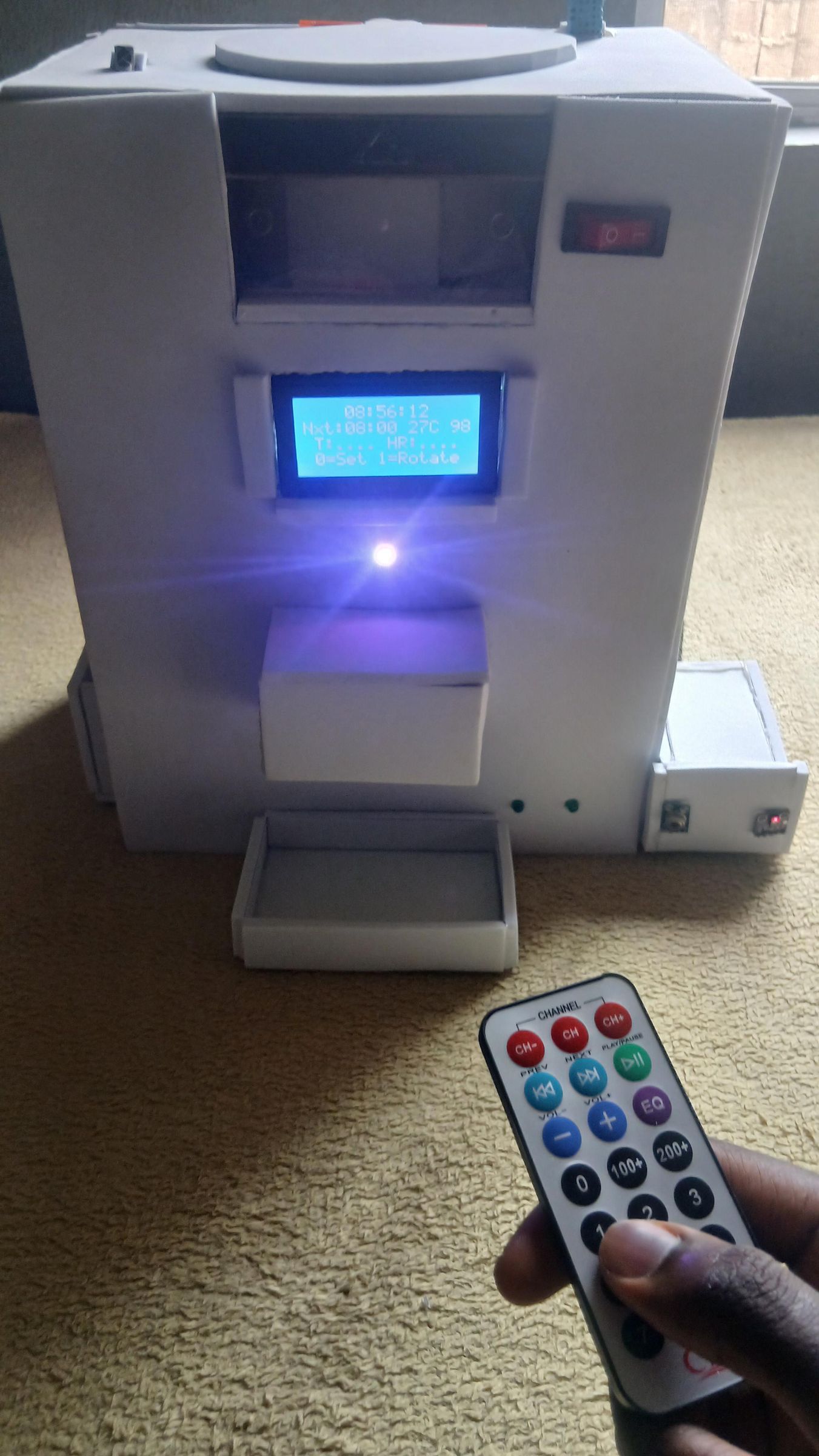
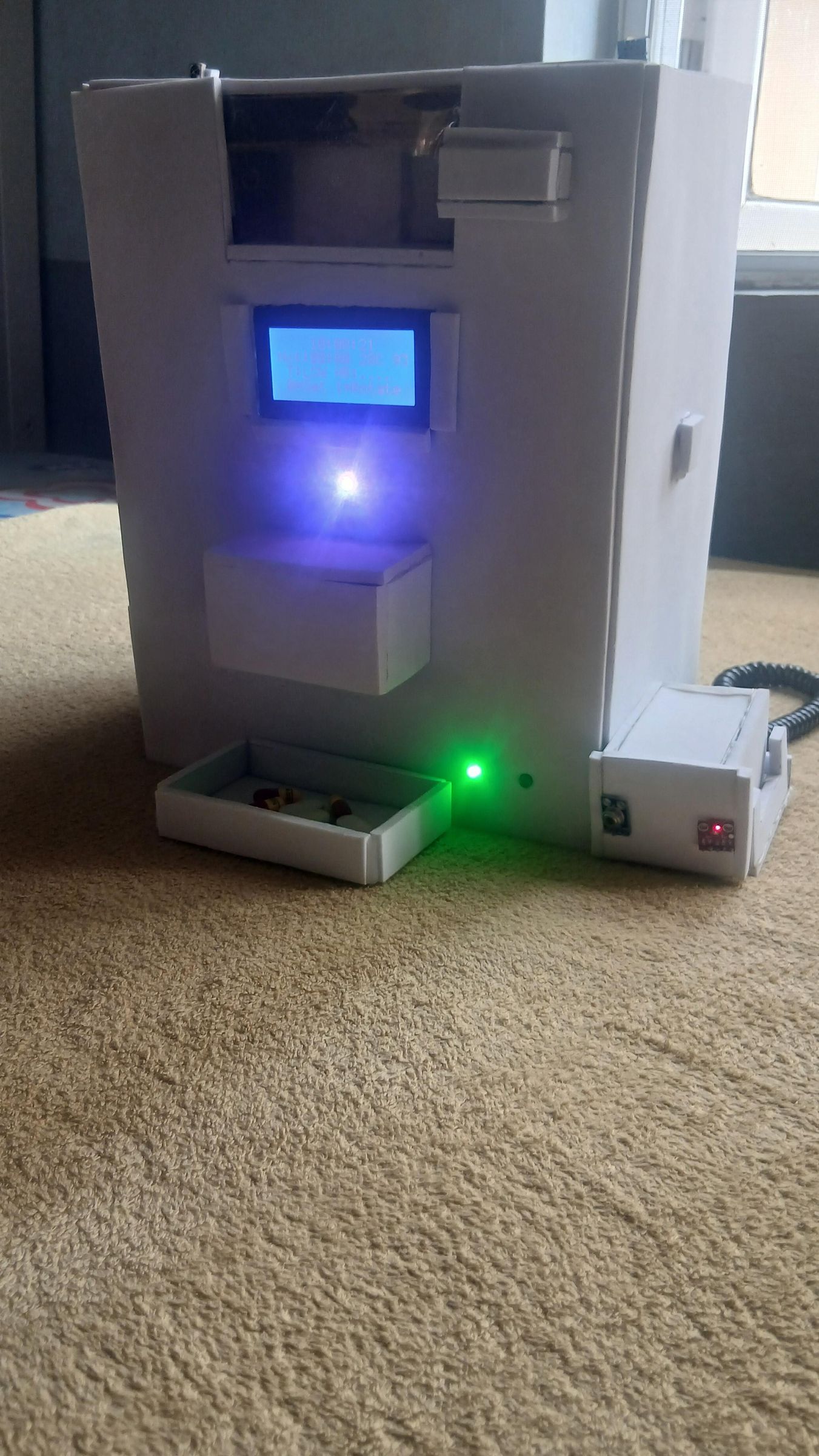
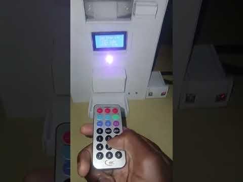
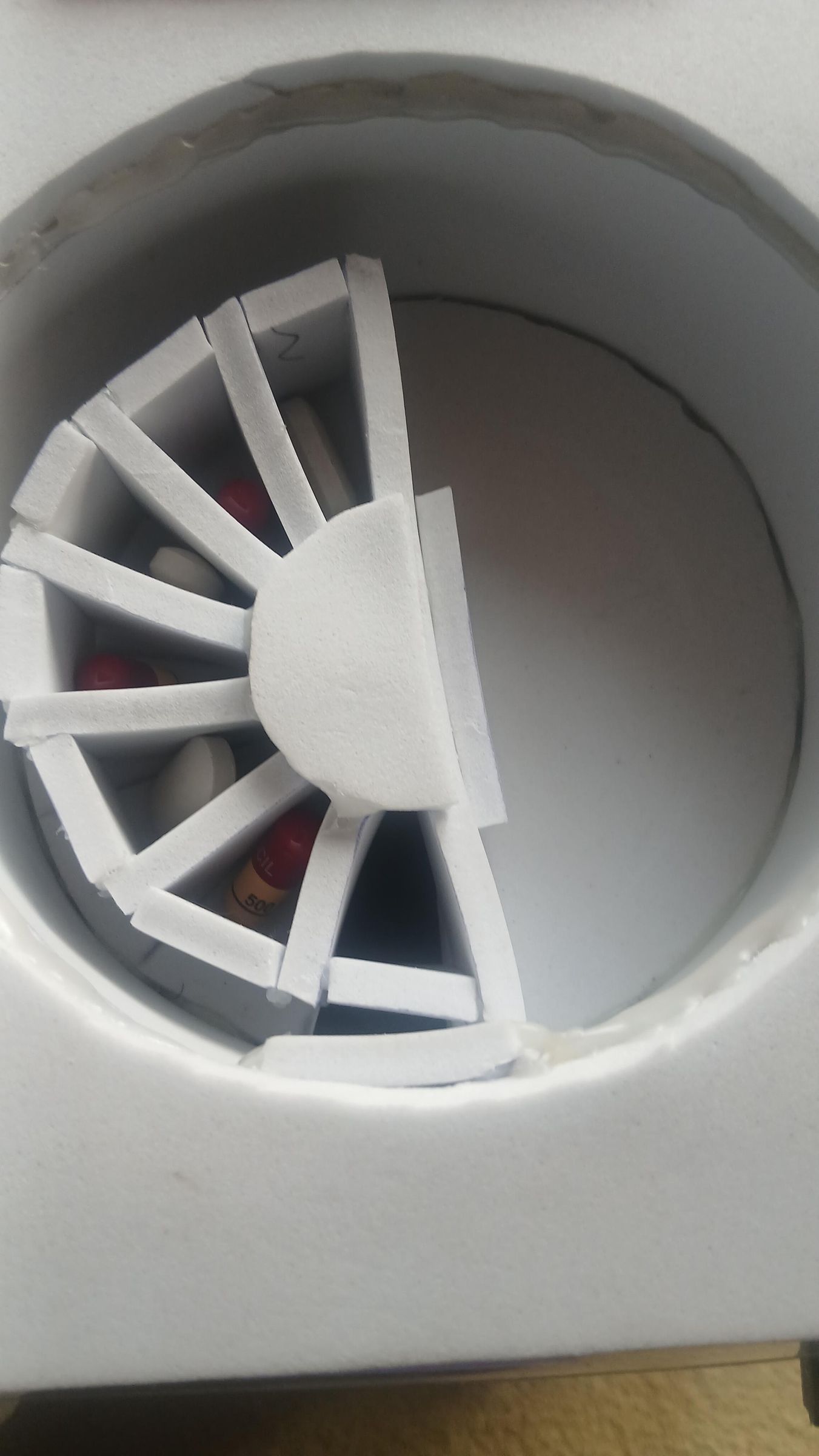
Medi-Sense V2 is an offline, battery-powered health companion built around an ESP32 microcontroller. It does two jobs that are usually handled by two separate devices: it dispenses medication on a schedule from a six-slot servo-driven mechanism, and it monitors vital signs — body temperature, heart rate, and blood-oxygen (SpO₂) — displaying everything on a local screen and relaying alerts over Bluetooth to a caregiver.
The whole point is to work without WiFi, cloud accounts, or a smartphone app. That makes it suited to elderly or non-technical users in rural and resource-constrained settings, where a device that depends on the internet simply won't be reliable. The user interacts with it through a simple IR remote — press a button to confirm you've taken your pill, and the system logs it; miss a dose and the alarm and Bluetooth alert fire.
Because it runs entirely off an 8000 mAh USB power bank, Medi-Sense V2 is fully portable and keeps working through power outages — which is exactly why it fits the Battery-Powered contest. In bench testing against clinical reference instruments it held up well, with measured errors of 0.28 % for temperature, 1.04 % for SpO₂, and 2.82 % for heart rate.
In this Instructable I'll walk through the full build: gathering parts, constructing the enclosure, wiring the electronics, loading the firmware, and testing the finished device.
Supplies
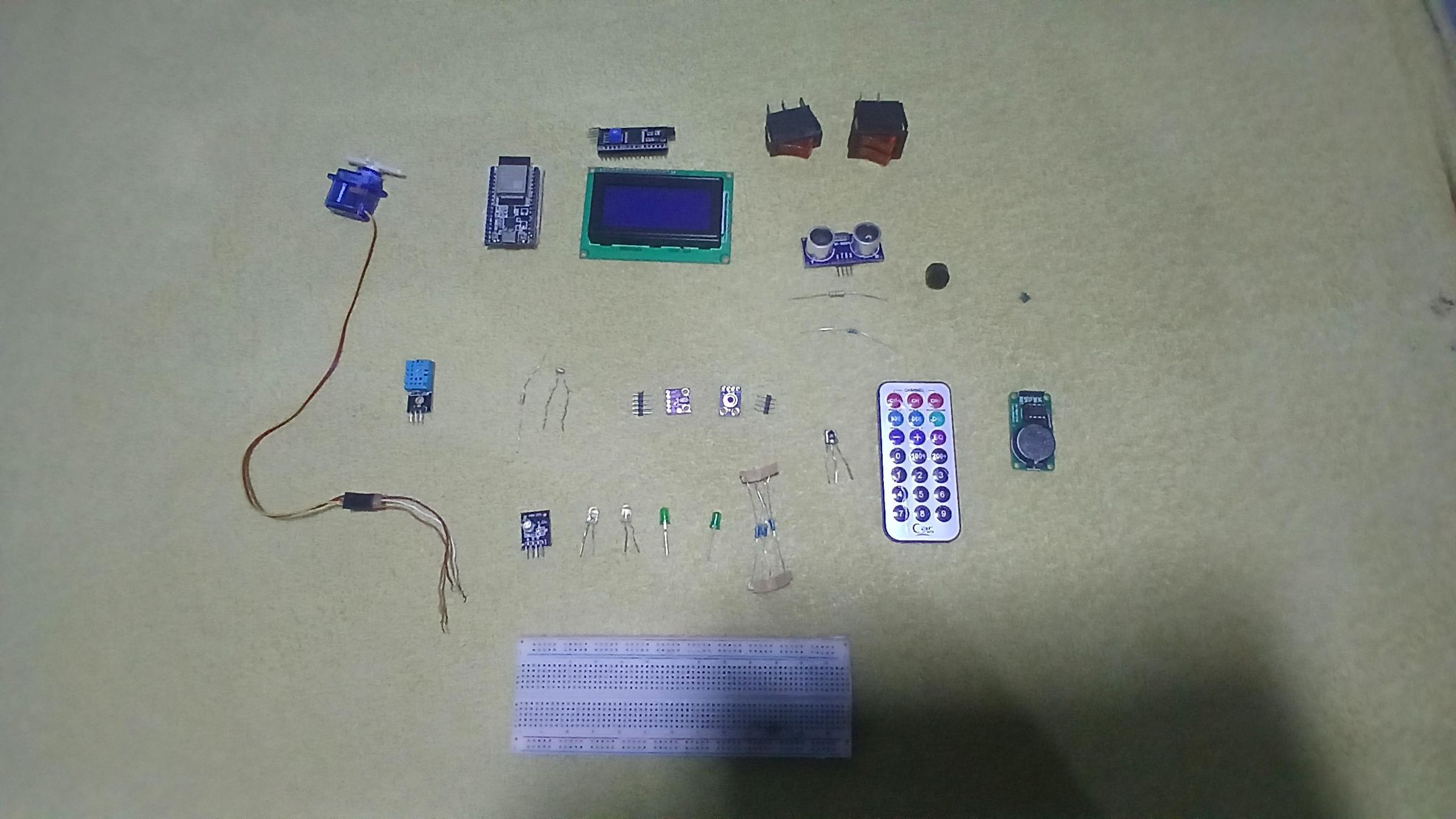

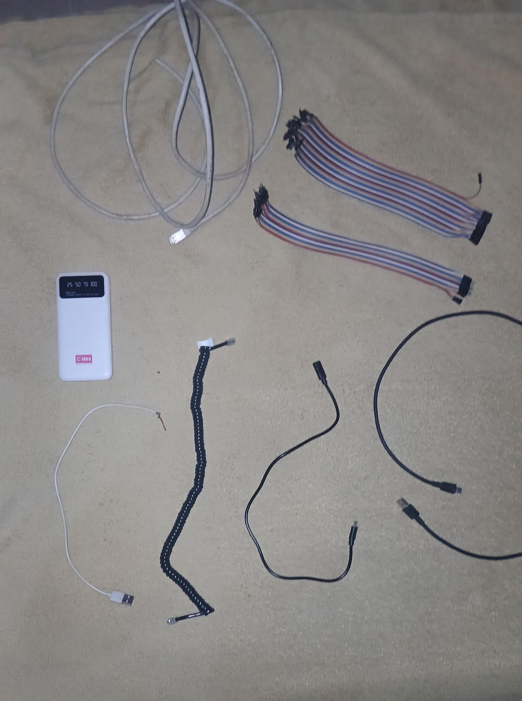
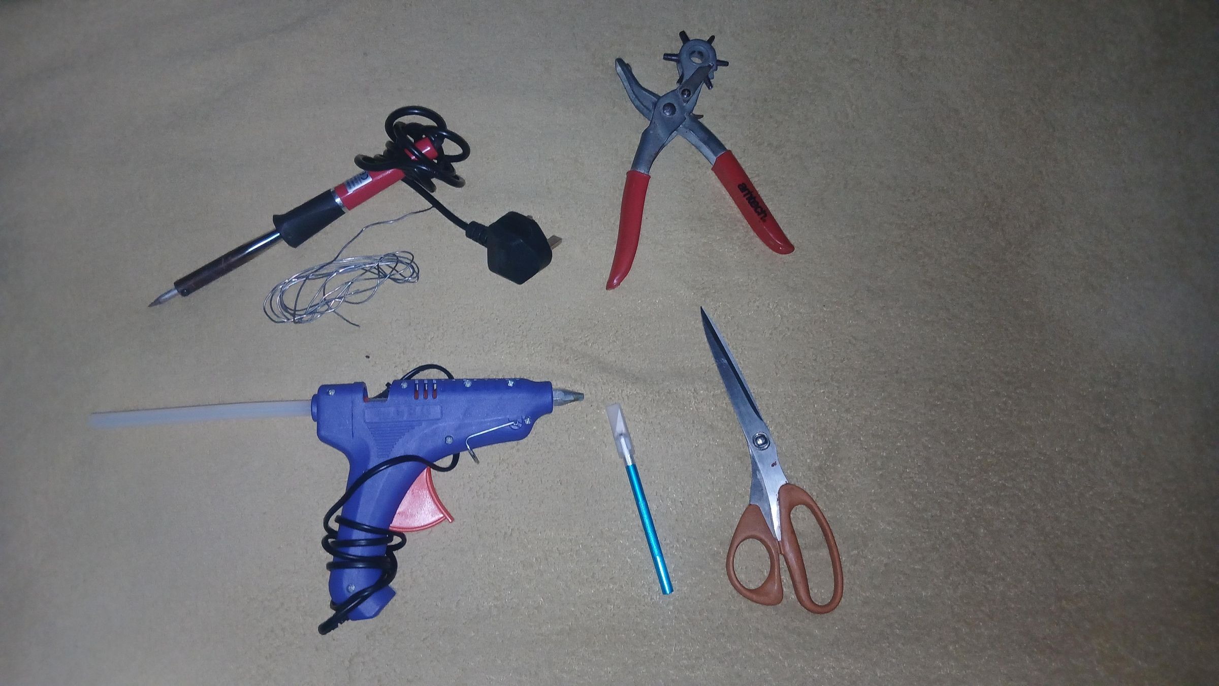
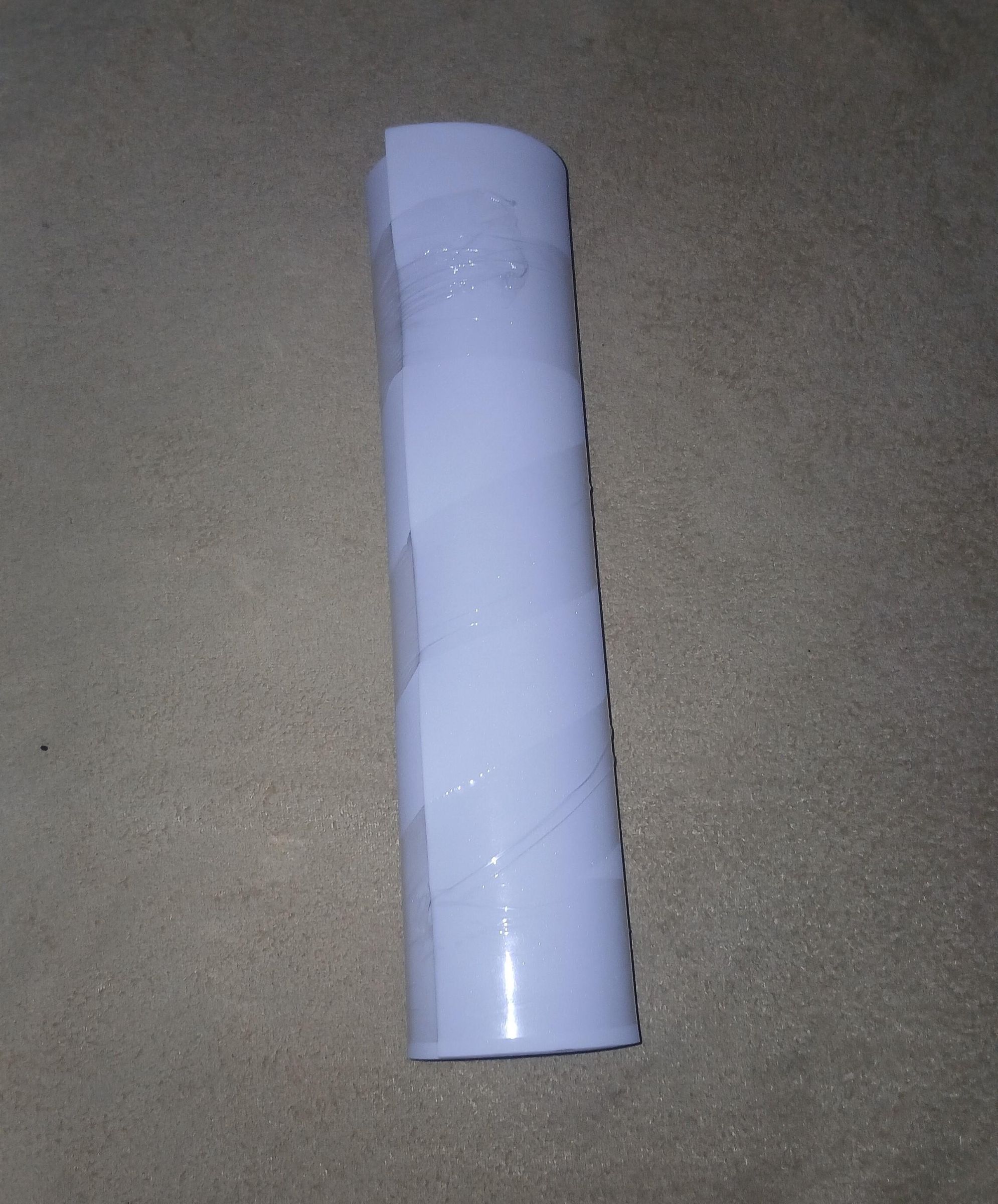
Here's everything that goes into Medi-Sense V2. I sourced low-cost, widely available modules so the whole thing stays affordable and repairable.
Electronics — the brain & sensors
- ESP32 dev module ×1 — the main controller, handling sensors, scheduling, display, and Bluetooth
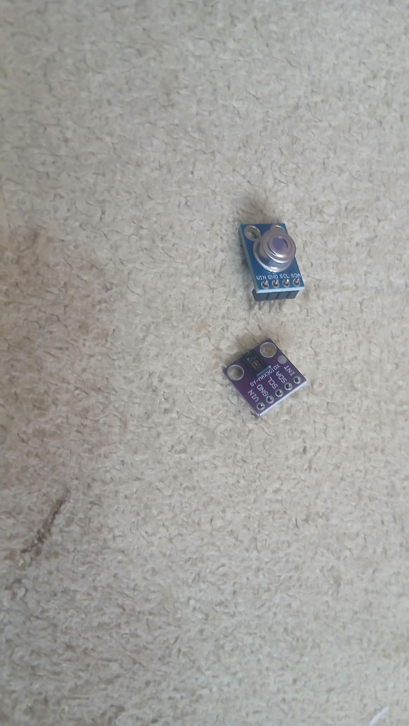
- MLX90614 non-contact infrared temperature sensor ×1 — measures body temp without touching the skin
- MAX30102 pulse-oximeter ×1 — heart rate and SpO₂
- DS3231 / DS1302 real-time clock module ×1 — keeps accurate medication timing even when powered off
- DHT11 temperature & humidity sensor ×1 — ambient room conditions
- 16×4 I²C LCD ×1 — shows status and live vital signs
- SG90 servo motor ×1 — drives the six-slot pill-dispensing wheel
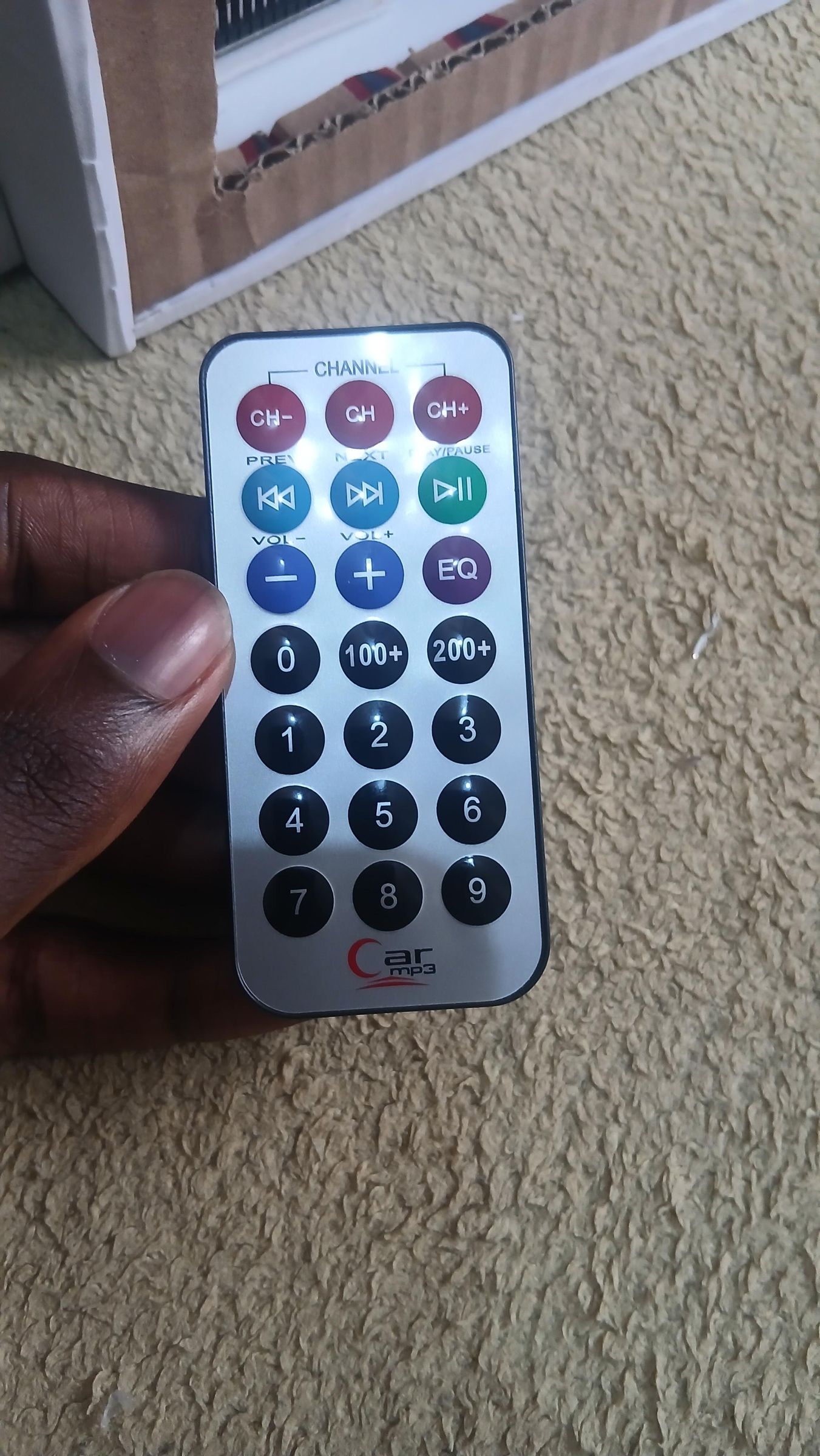
- VS1838B IR receiver ×1 + standard IR remote ×1 — the main user interface
- Active buzzer ×1 and passive buzzer ×1 — alarms and prompt tones
- Green & white LEDs ×5 — visual status indicators
- 150 Ω resistors ×4 — current limiting for the LEDs
- HC-SR04 ultrasonic sensor ×1 — appears in my parts photo but was removed from the final build (see note below)
- LDR / photoresistor ×1 — appears in my parts photo but was removed from the final build (see note below)
Power
- 8000 mAh USB power bank ×1 — the device's rechargeable power source
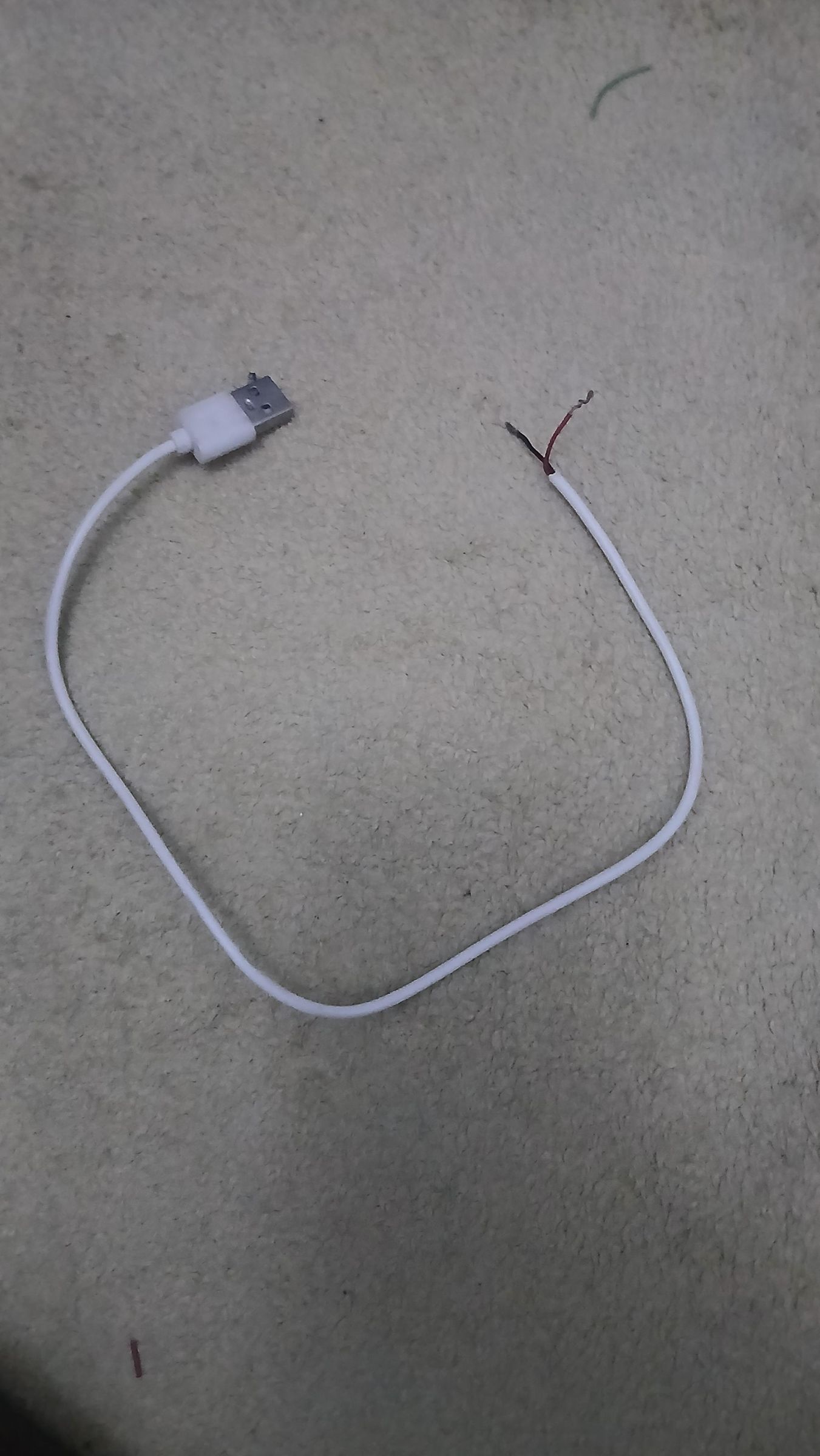
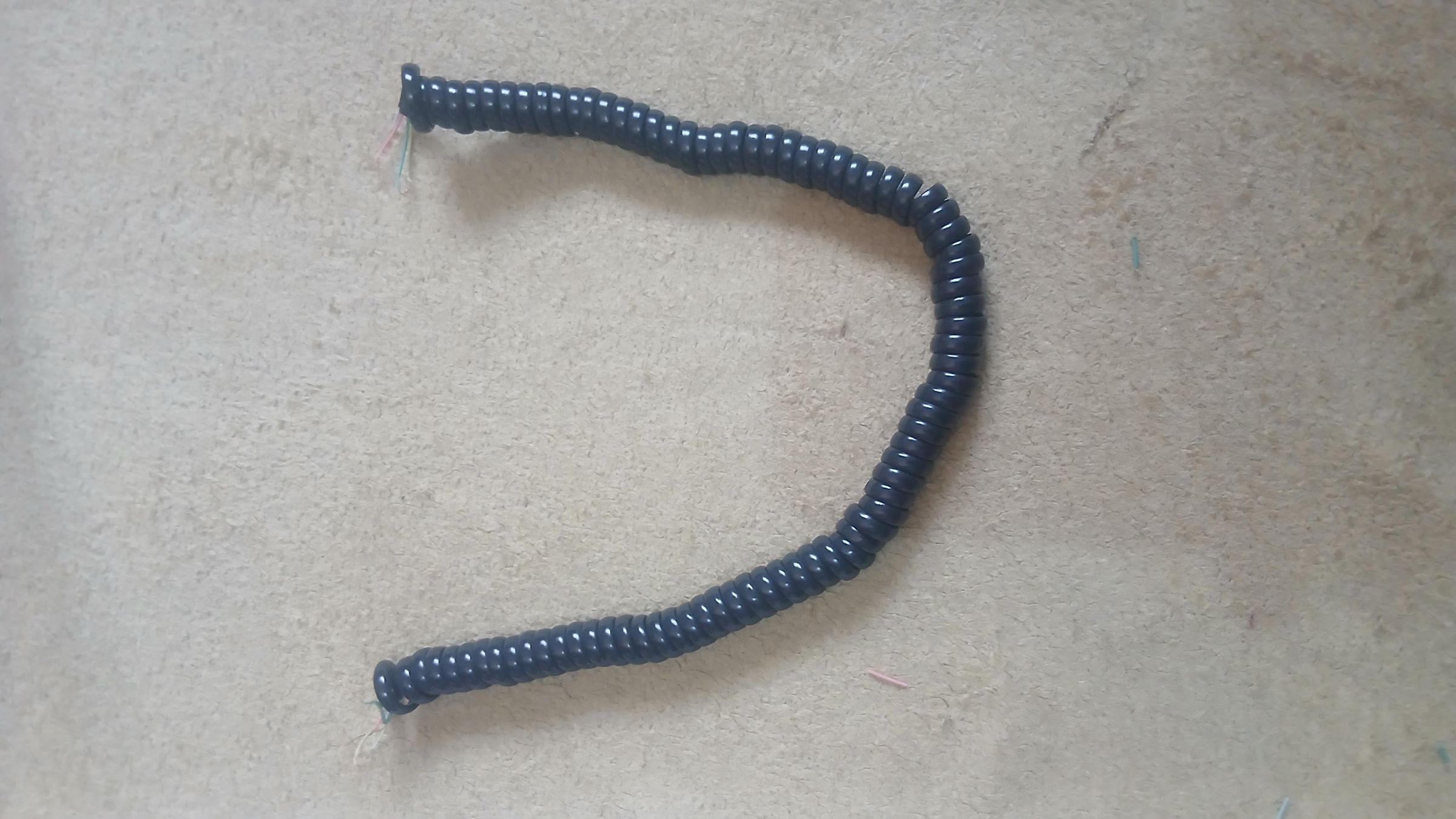
- Type-C (male-to-female) extension + curly phone-cord / Cat-6 lead ×1 each — carry power and signal to the vital-sign unit
- Double (dual) toggle switch ×1 — the working power control (see note below)
- Single toggle switch ×1 — included in the build but disabled; see note below
Prototyping & connections
- Breadboard ×1
- Jumper wires — several (male-male, male-female)
Enclosure & build materials
- 5 mm foam-board for the body
- Cheese balls Party Pack size box
- Glue, tape
Tools
- Soldering iron + solder
- Hot glue gun + glue sticks
- Craft/utility knife
- Scissors
- Hole-punch pliers
- Ruler, pen/pencil for marking
A note on two sensors I deliberately left out
You'll spot two extra sensors in my parts photo that didn't make the final build — I'm leaving them in the picture (and list) so the change makes sense:
- Ultrasonic sensor (HC-SR04) — removed for drug security. My first design used an ultrasonic sensor to auto-detect a hand under the dispenser and release the pill automatically. It worked, but it opened a real loophole: anyone — including a small child — could simply wave a hand under the outlet and trigger a dose. For a device whose whole job is safe, controlled medication, that was an unacceptable security gap. I replaced automatic hand-detection with deliberate user confirmation via the IR remote (or a Bluetooth command), so a dose only releases when the user actually intends it.
- LDR (light sensor) — removed as redundant. I'd planned to use an LDR to manage the indicator lighting, but it turned out unnecessary: the white LEDs already switch on automatically whenever a drug is dispensed, so the dispensing event itself drives the lighting. The LDR added parts and wiring without adding function, so it came out.
Both removals made the device simpler, cheaper, and — in the ultrasonic case — meaningfully safer.
A note on the power switches
You'll also see two different switches in my photos — a single and a double — and only one ends up doing the work:
- Single switch (disabled). This was meant to cut power to just the vital-sign monitor to save battery. In practice, switching it off seized the I²C bus (SDA/SCL) shared by the temperature, SpO₂, and LCD modules, locking up that side of the system. Rather than risk an unstable bus, I blocked it off and left it disabled.
- Double switch (the one in use). This carries the load instead. The first pole powers the servo motor independently, and the second pole powers the ESP32 (the whole system on/off). That first pole is the useful battery-saver: switch the servo off when you only want vital-sign monitoring, and the dispensing motor draws no power while temperature, heart-rate, and SpO₂ monitoring keep running off the ESP32.
The dual switch ended up being the smarter power-management solution — a "monitor-only, servo-off" low-power mode without ever touching the I²C bus the single switch was choking.
Building the Frame & Mounting the First Components
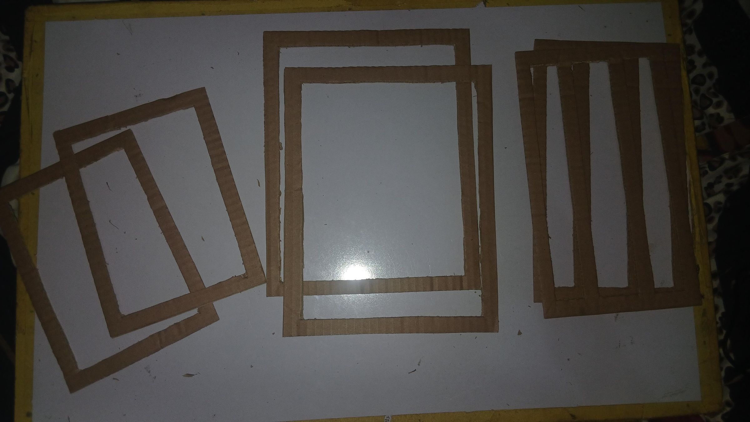
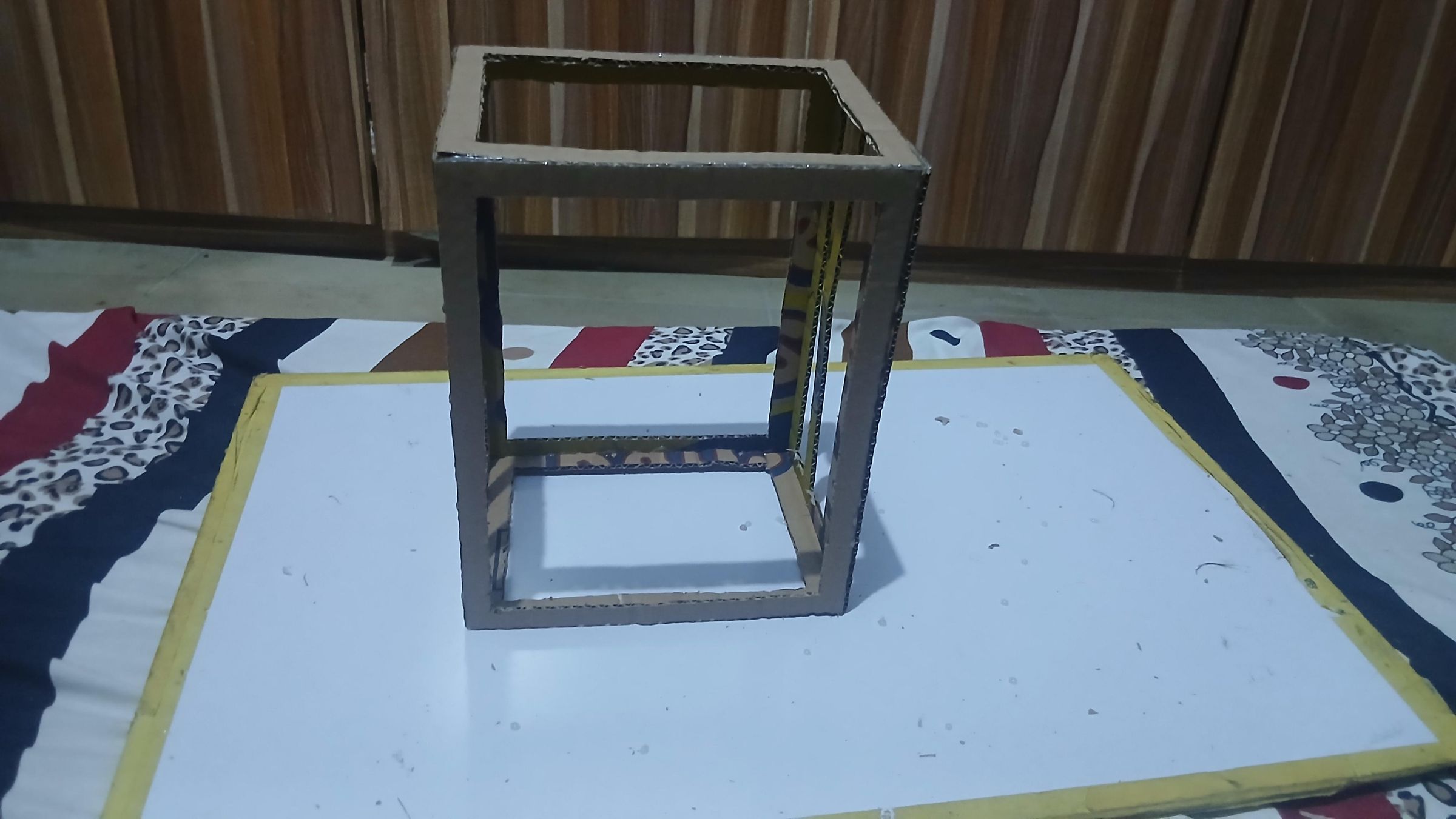
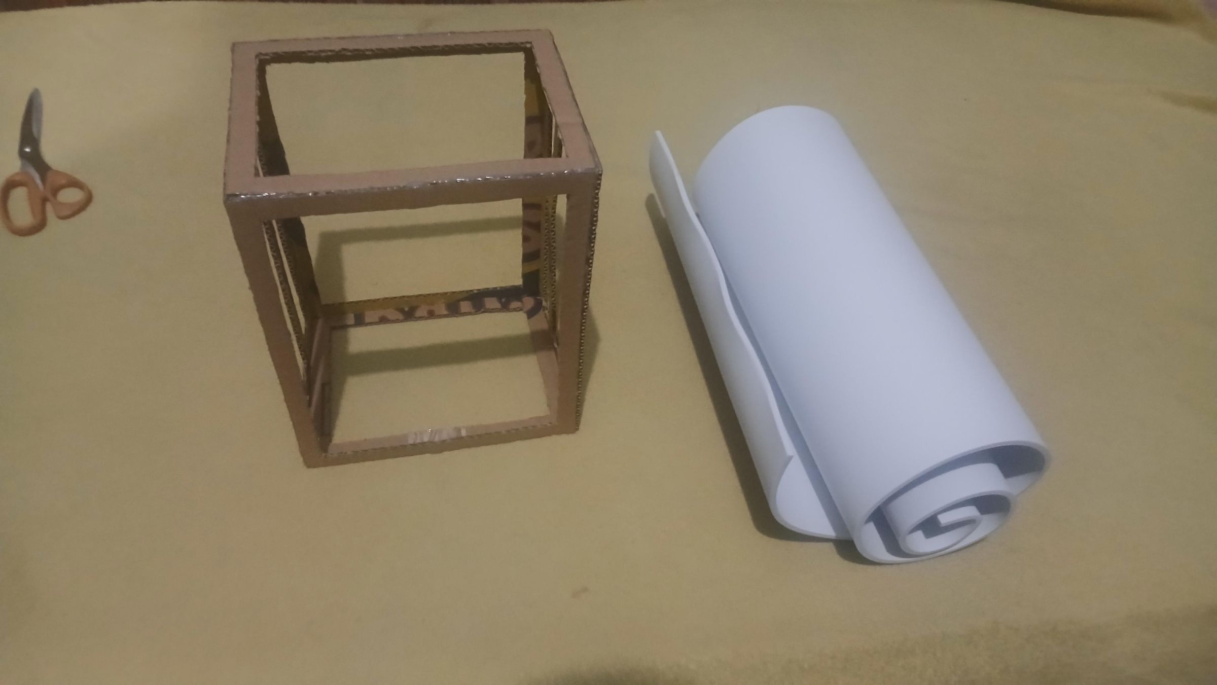
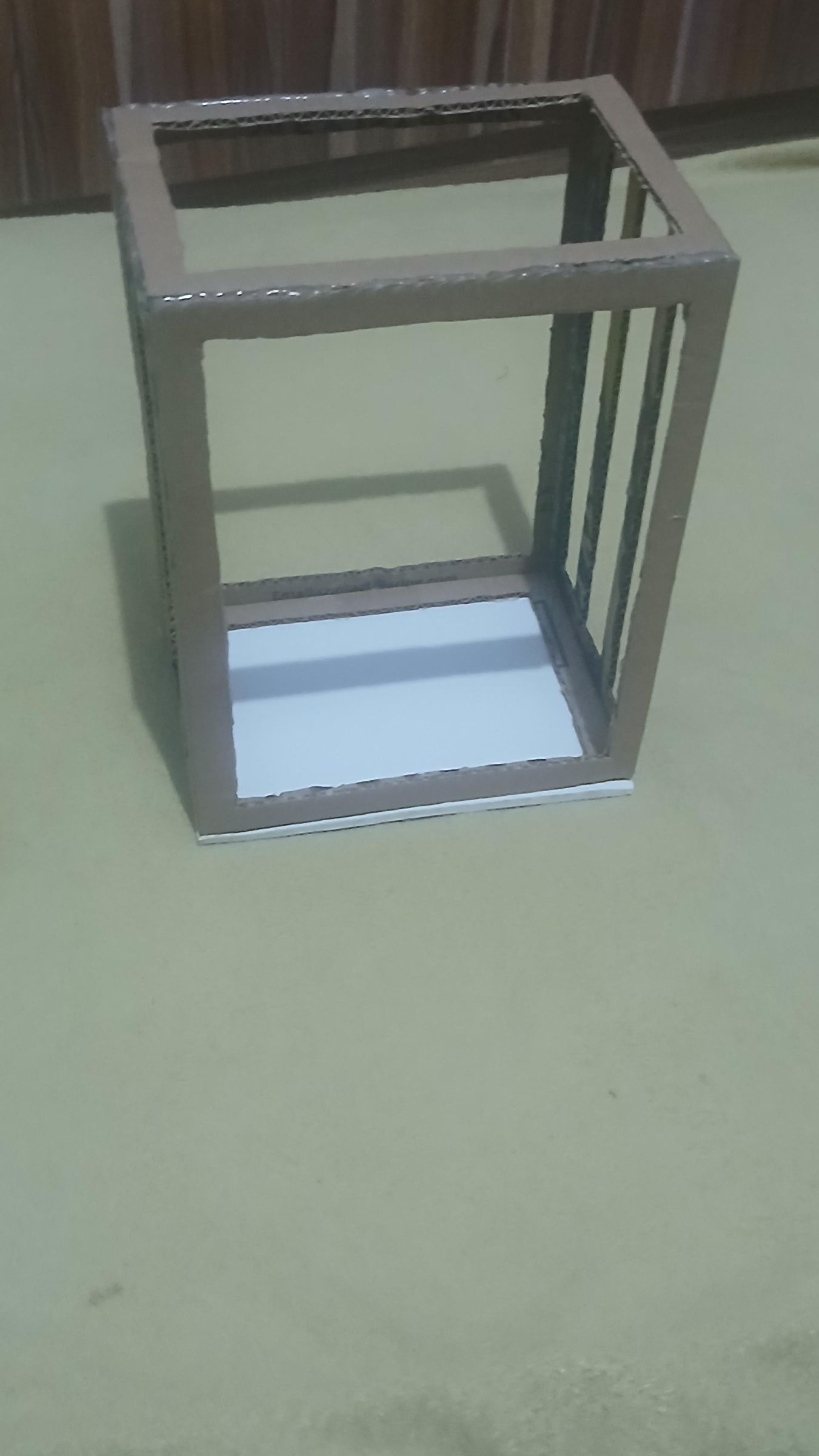
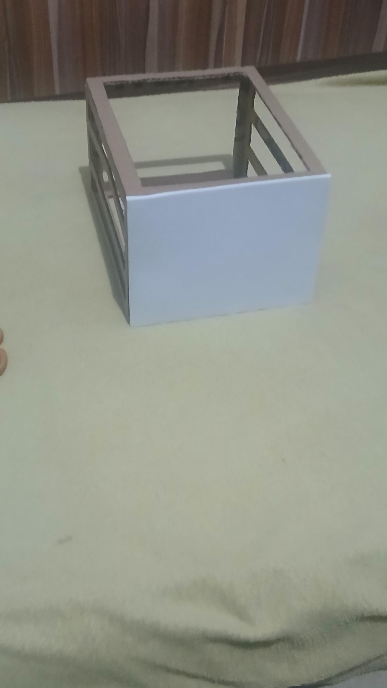
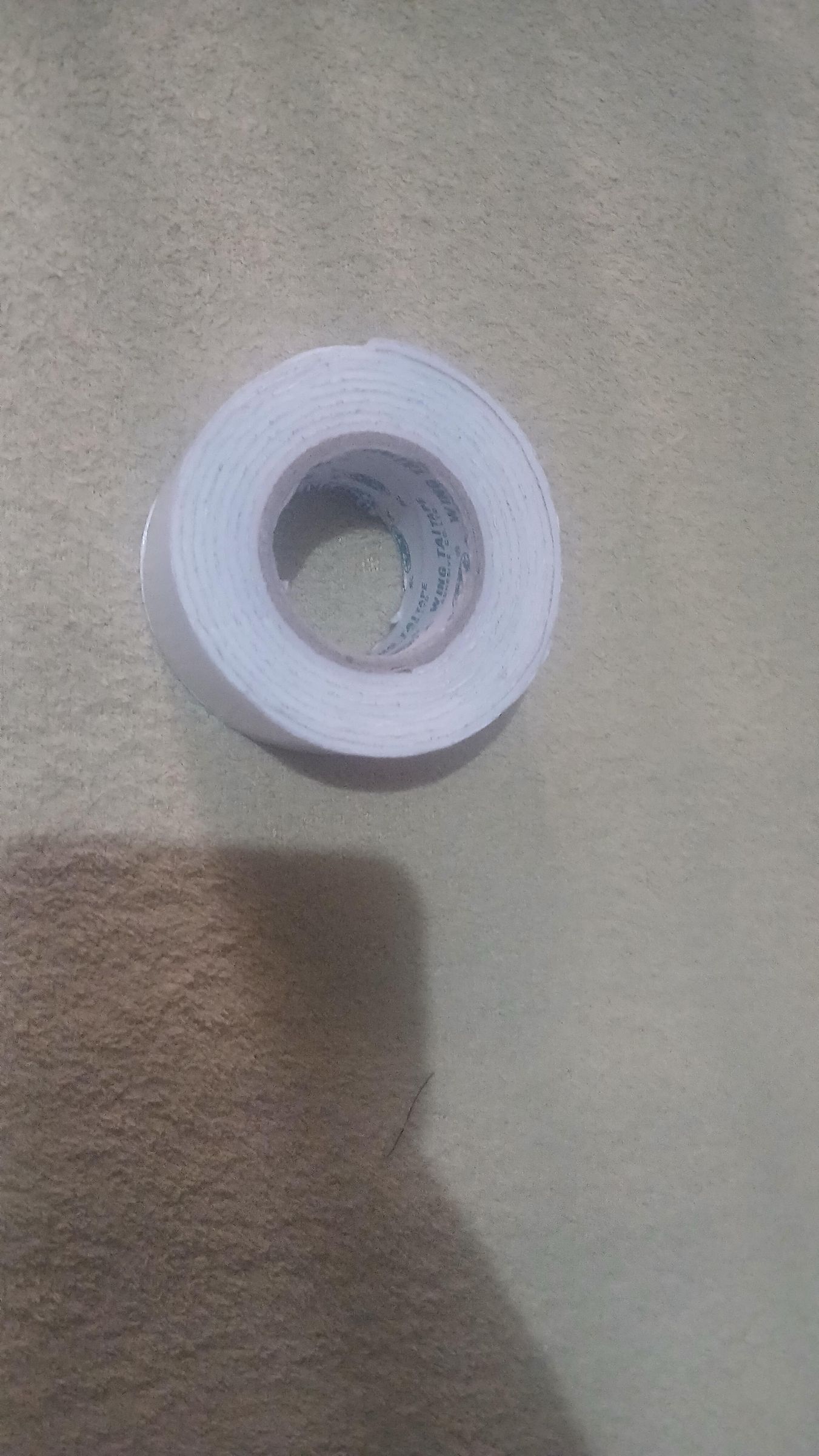
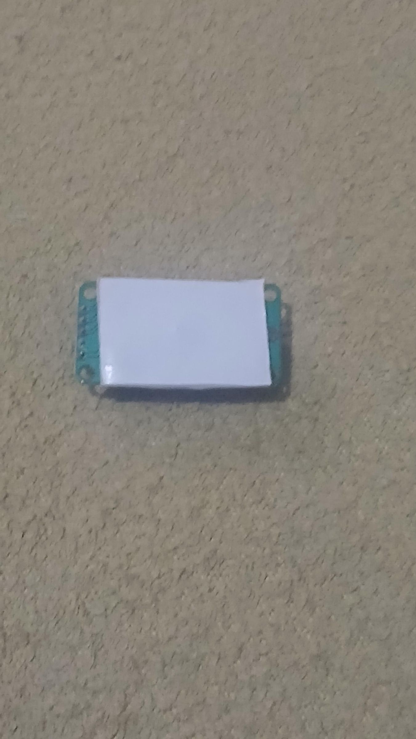
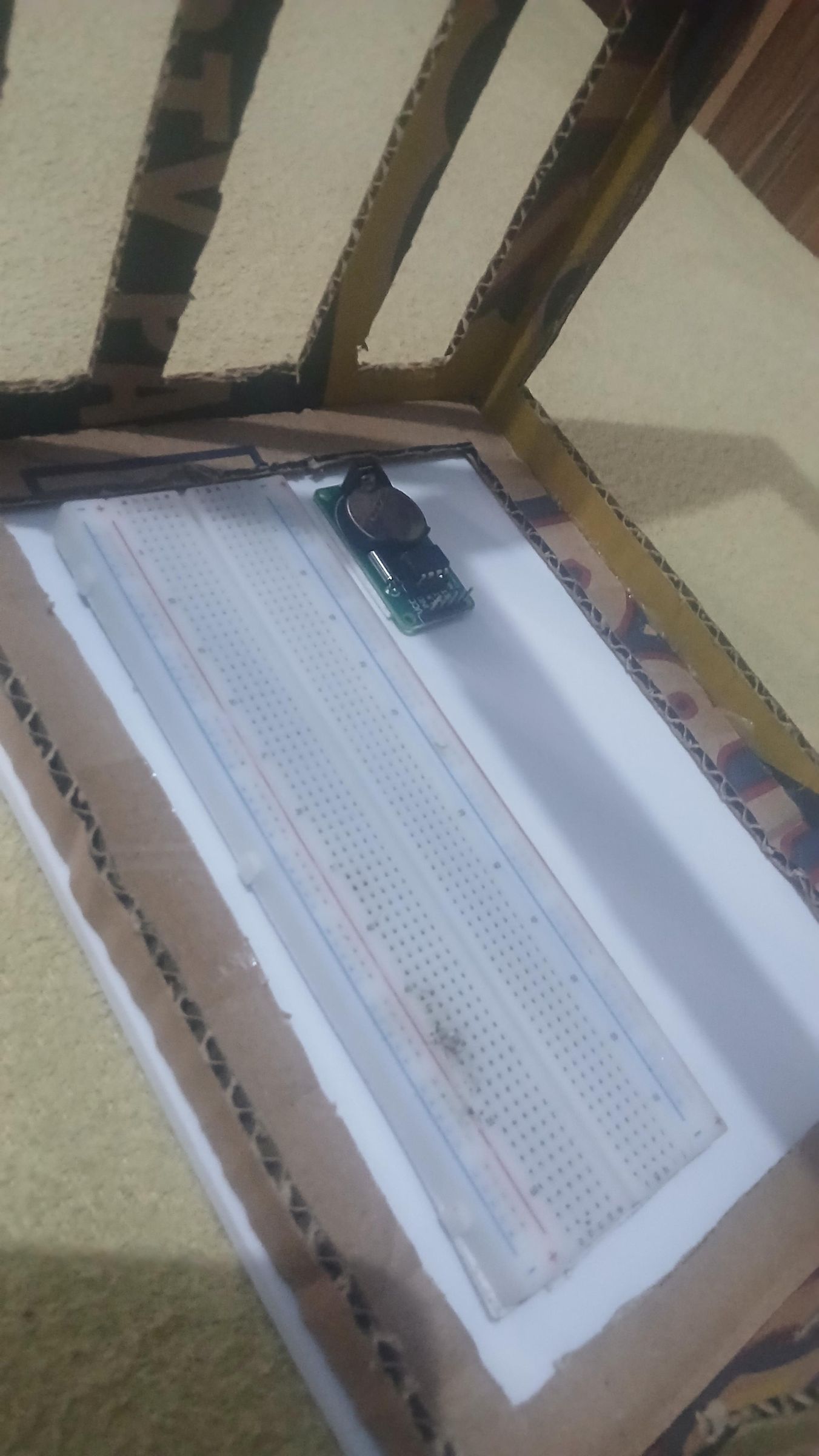
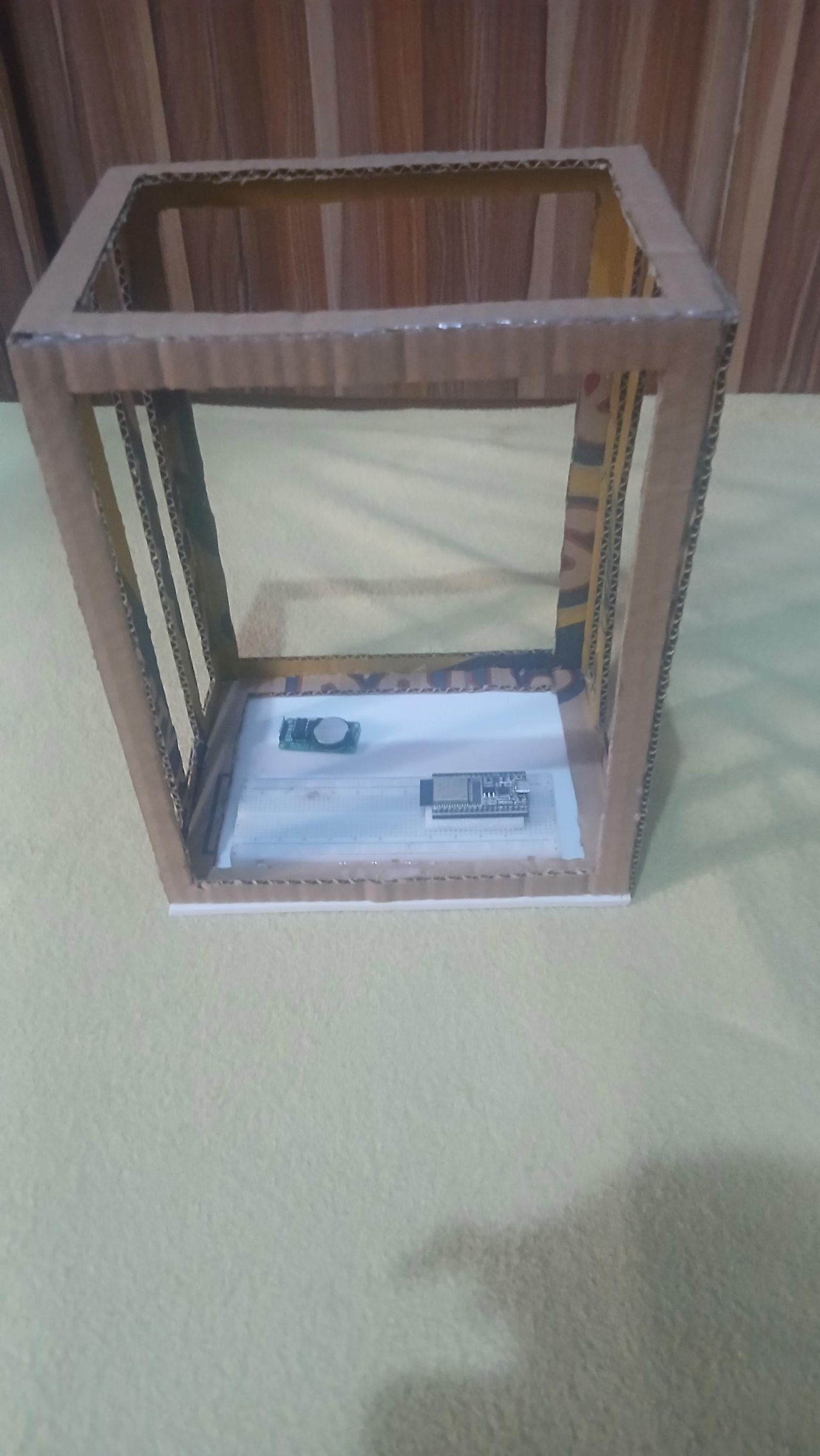
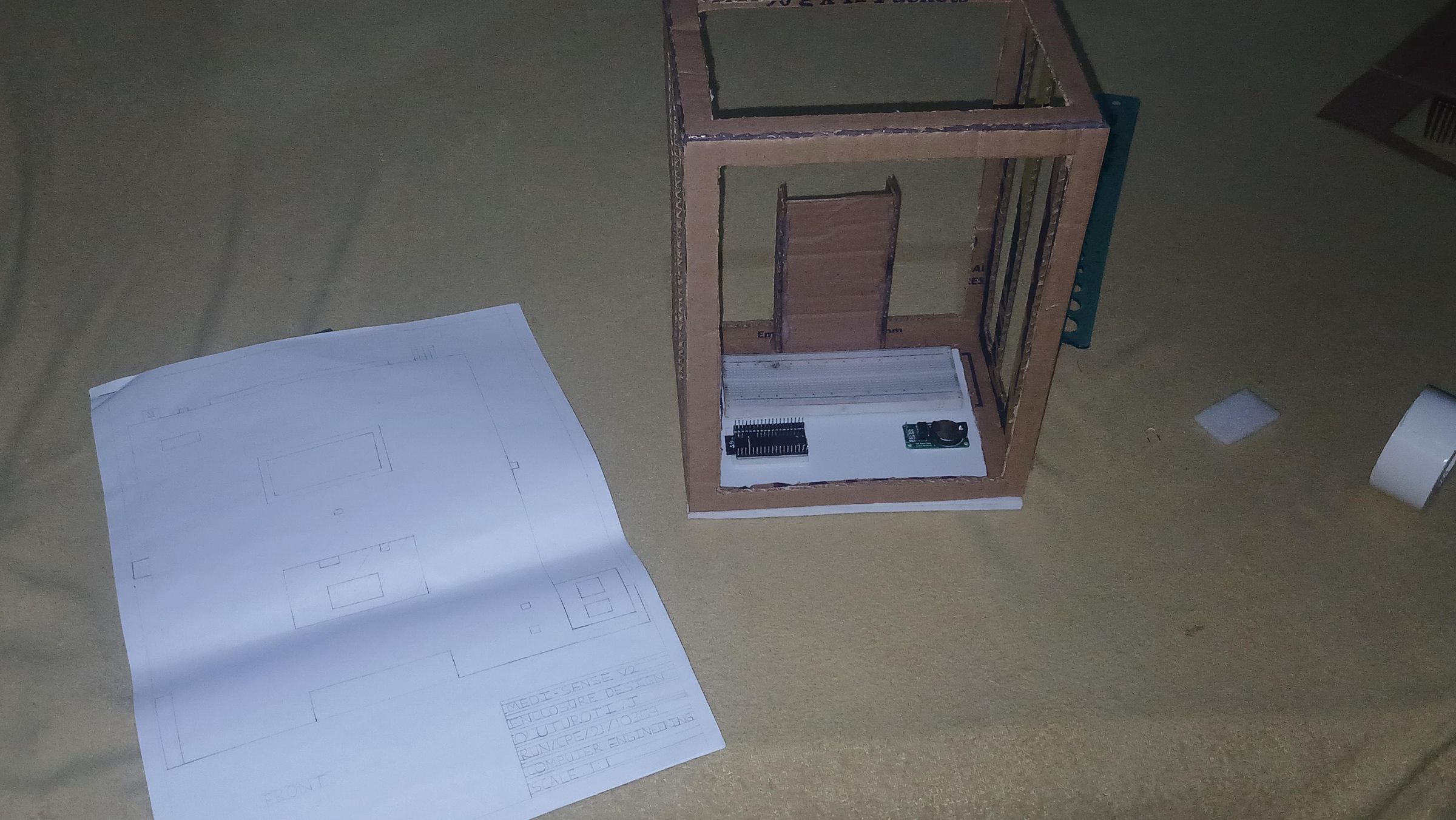
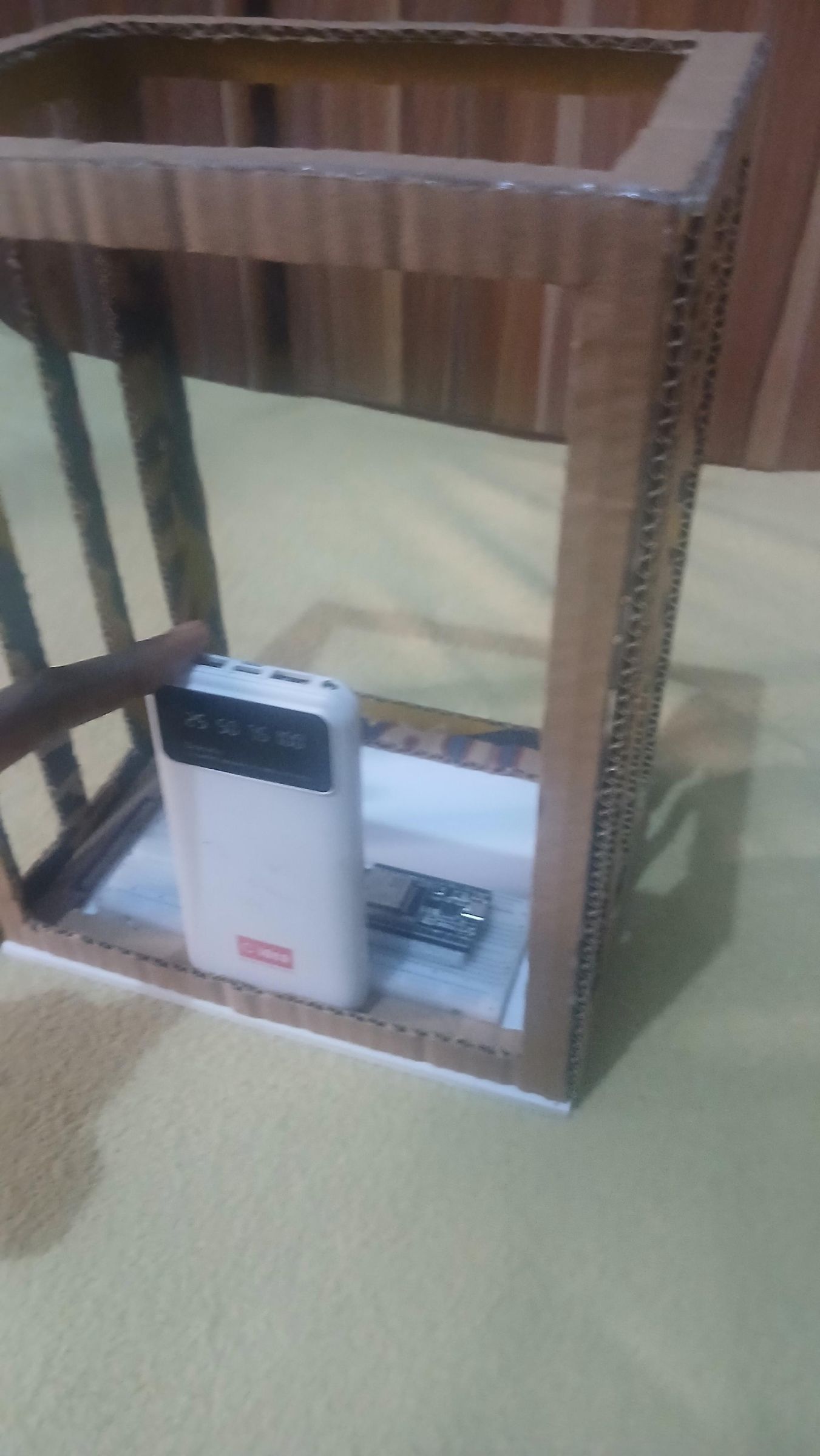
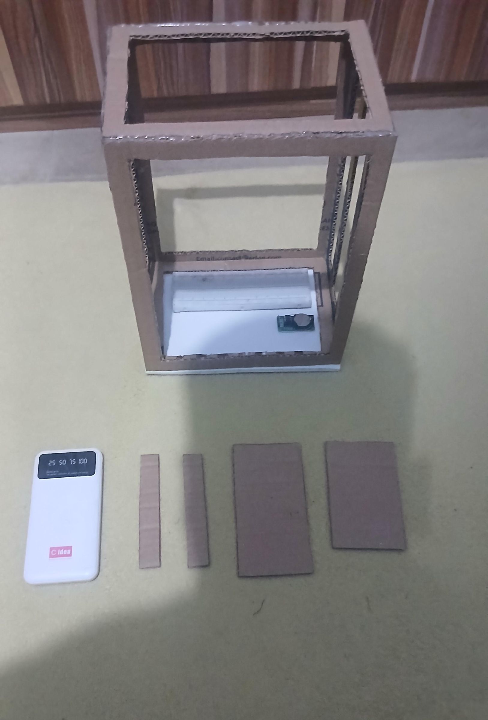
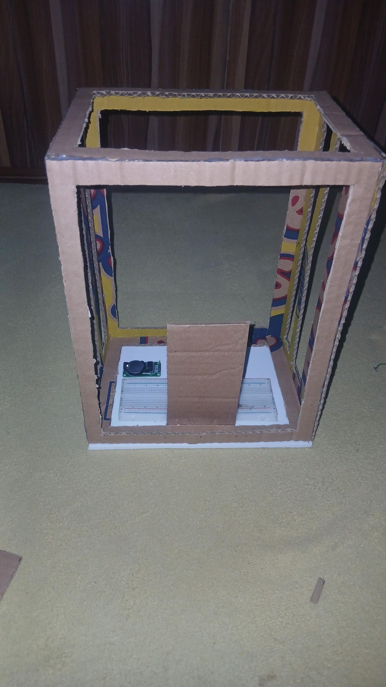
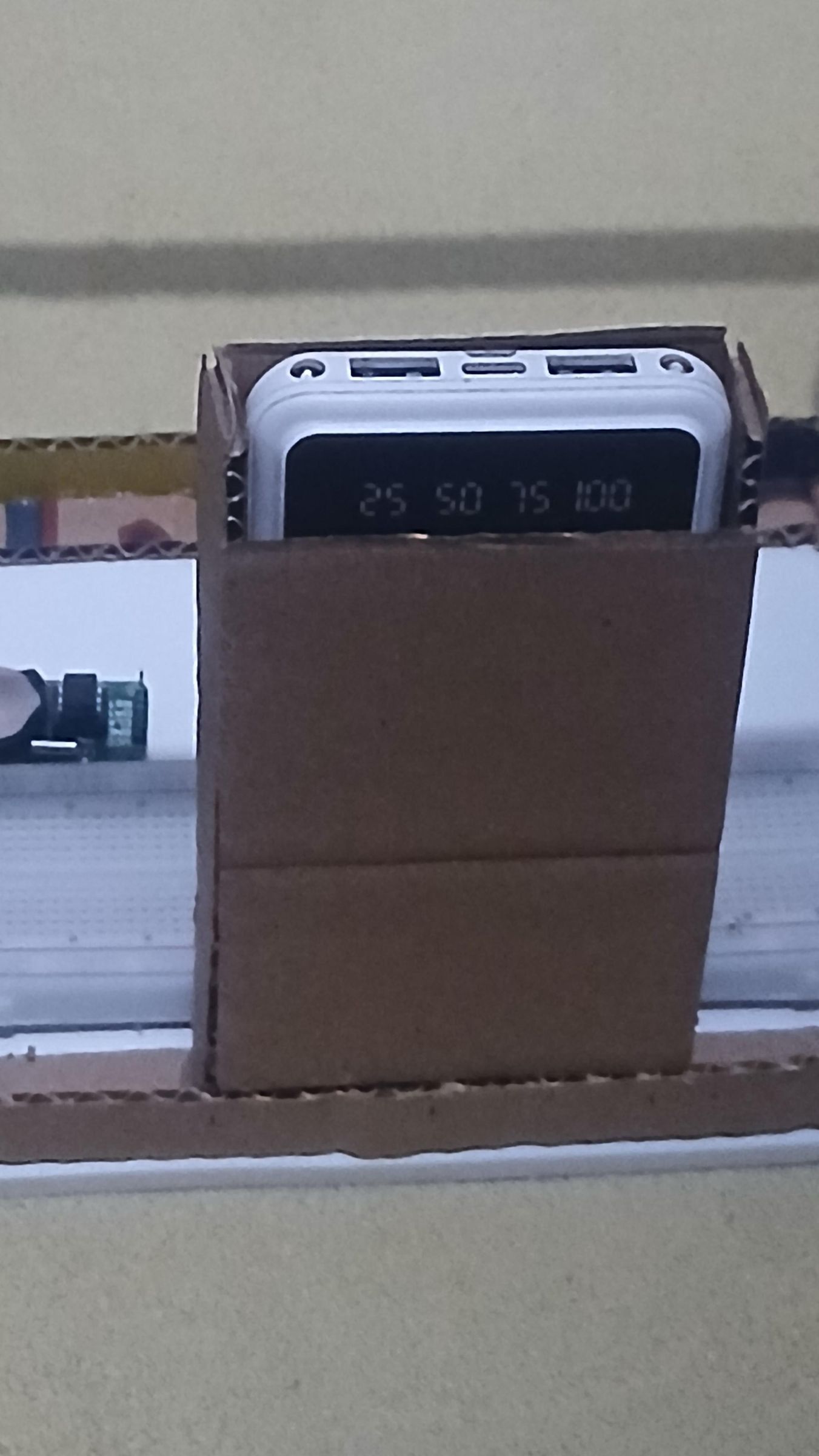
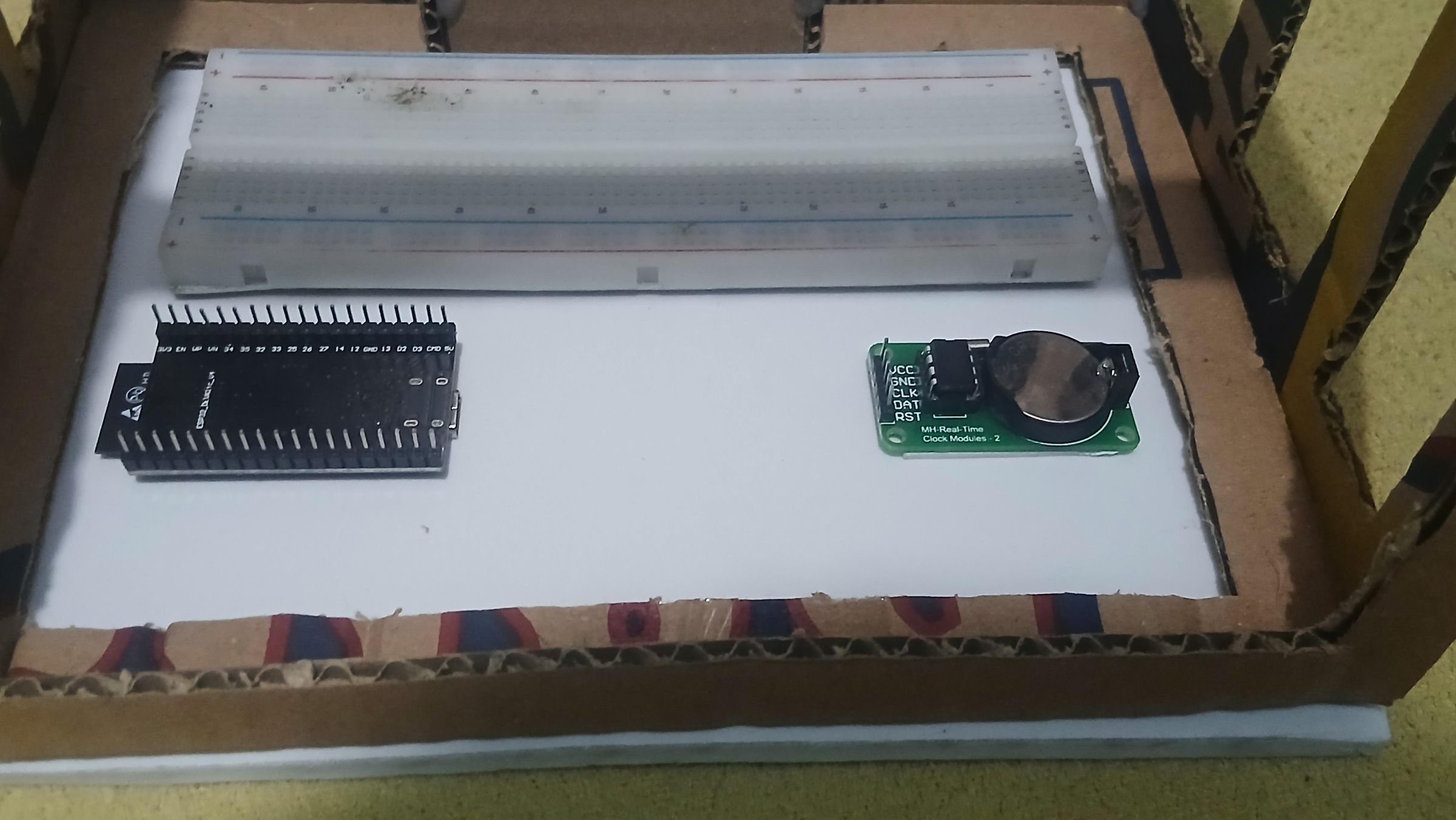
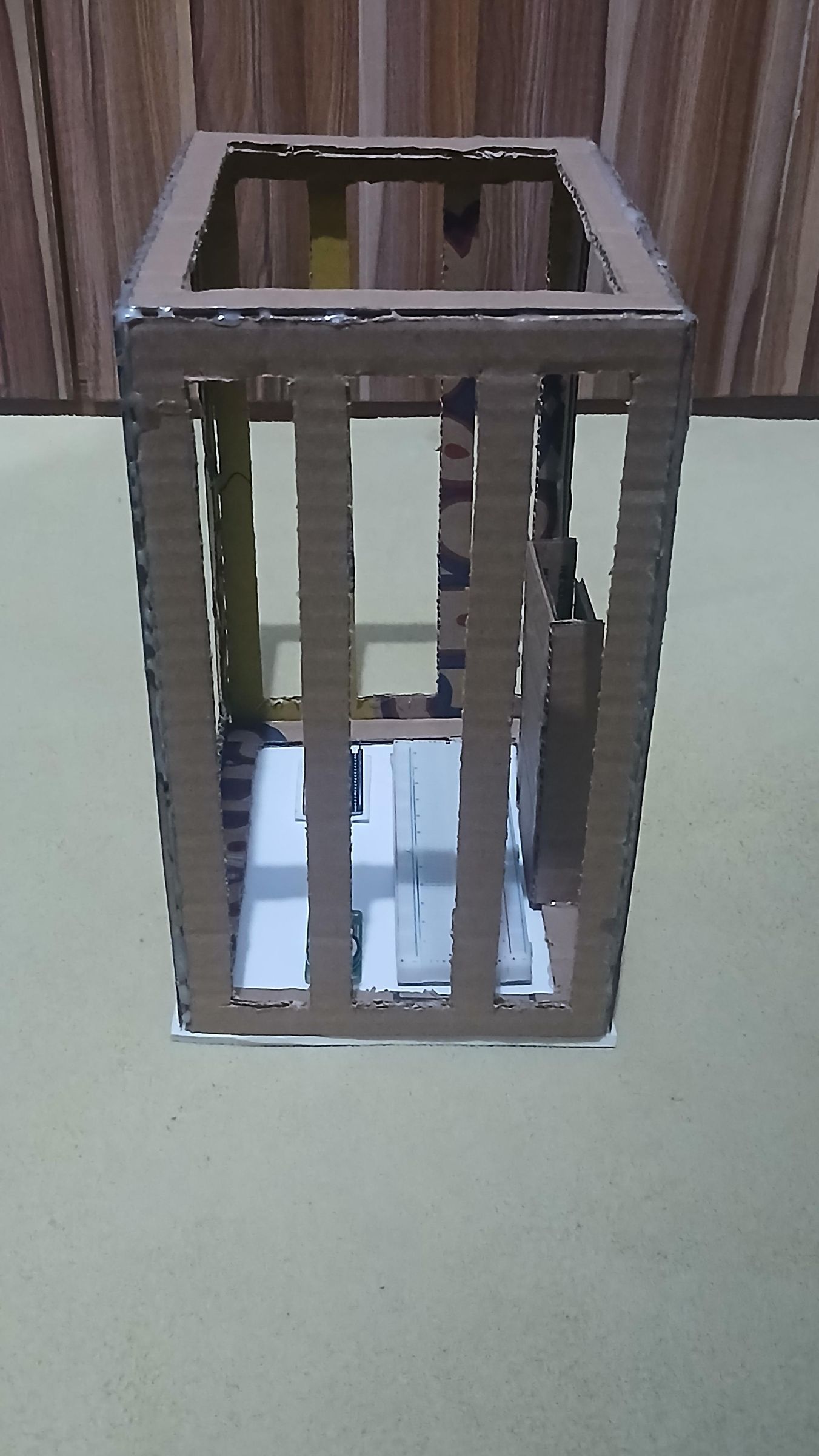
This step covers cutting and assembling the cardboard frame for the enclosure, paneling it with white foam-board, and mounting the first components — breadboard, ESP32, and DS3231 RTC module — along with building a small separate compartment for the power bank, all before the rest of the wiring goes in.
Outer Frame Dimensions (the Carton Frame — 1.5cm bracing width all round)
- Front & Back: 22 × 28 cm
- Left & Right: 16 × 28 cm
- Top & Bottom: 16 × 22 cm
- Gaps (left to right): 3, 4, 3 cm
What's happening in this step
- Cut the frame pieces. Starting from the upcycled Cheese Balls cardboard, I marked and cut multiple rectangular frame pieces — these stack up to form the four vertical struts plus top and bottom rectangles of the main enclosure box.
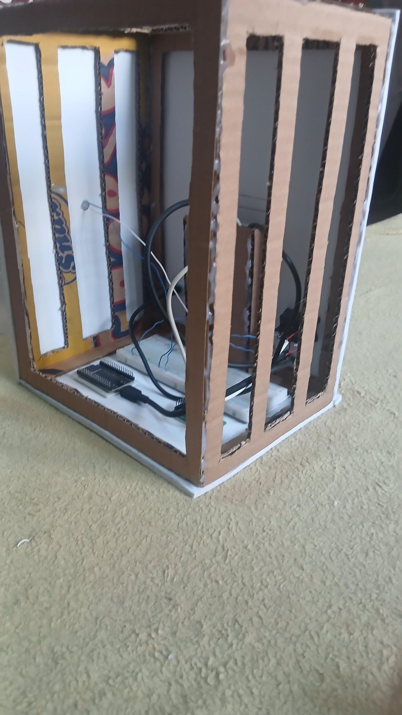
- Assemble the open frame. The cut pieces glue together into an open rectangular cage — a skeleton with a clear top opening and four corner struts, standing on its own.
- Add the side panels. A rolled sheet of white foam-board gets cut and glued onto the cardboard frame, one side at a time, to give the enclosure a clean, finished look rather than bare cardboard. By the end of this step at least one full side is paneled.
- Mount the breadboard. The full-size breadboard goes down first on the white interior base, secured with double-sided tape — it's the foundation everything else builds onto.
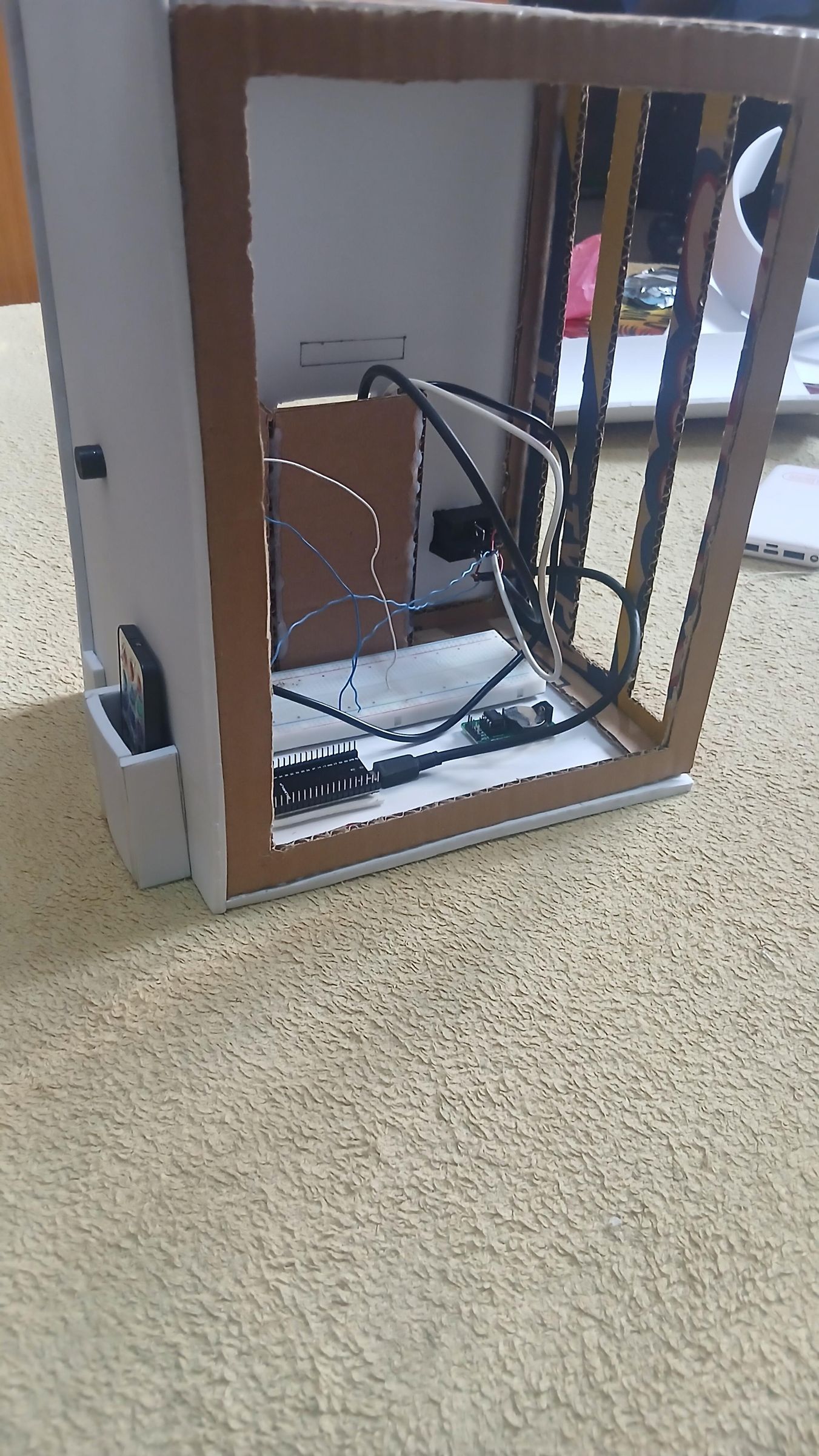
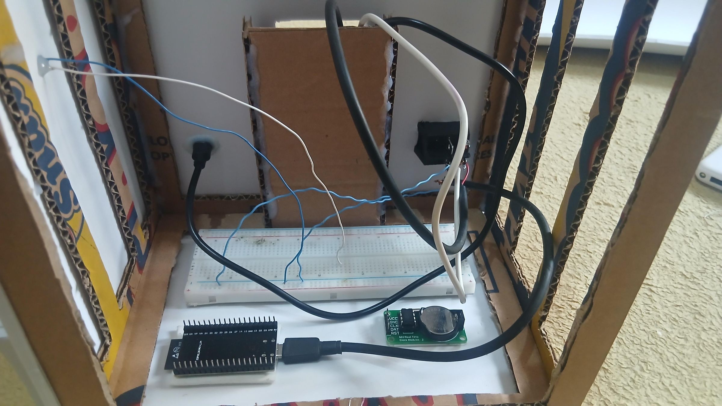
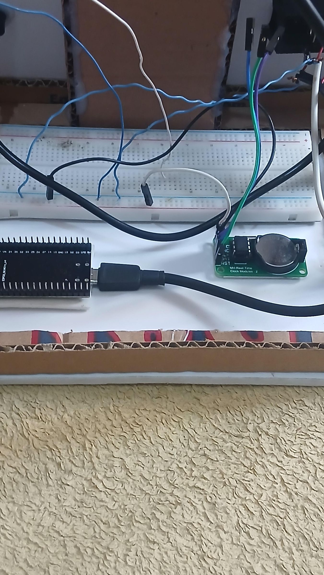
- Mount the ESP32 and the DS3231 RTC module. Both are also fixed in place with double-sided tape, sitting on the same base panel next to the breadboard — the ESP32 ready to be wired in, and the RTC module (with its coin-cell backup battery clearly visible) placed close by since it'll be among the first things wired up, to keep accurate time even when the main power is off.
- Build a separate compartment for the power bank. Rather than just resting the power bank loose inside the main enclosure, I built it its own small cardboard sleeve/holder with a cutout so its battery-percentage display (visible showing 25/50/75/100%) stays readable from outside. This keeps the power source organized and separate from the sensitive electronics.
Building the Frame, Mounting Core Components & Wiring the Back Panel

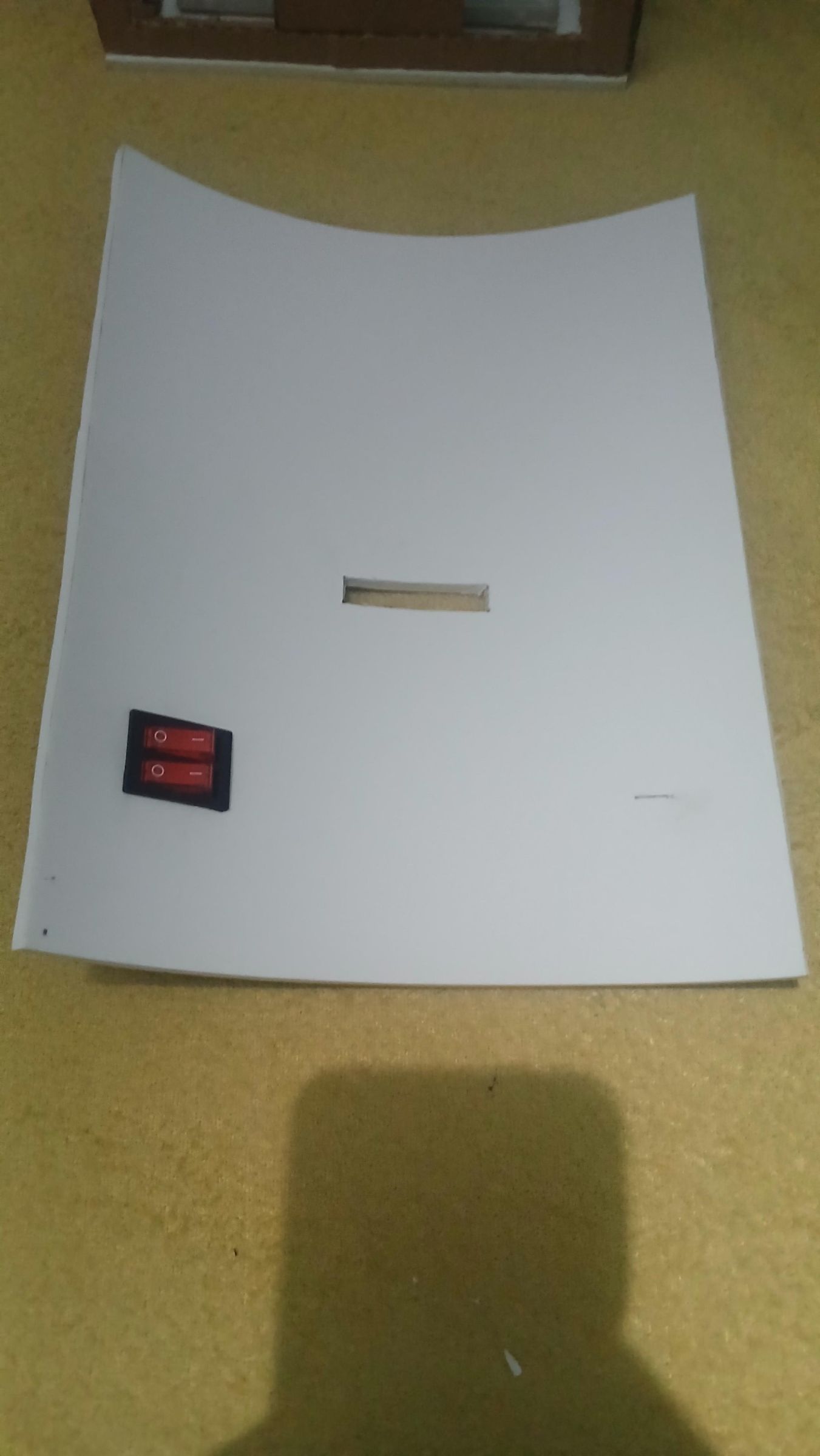
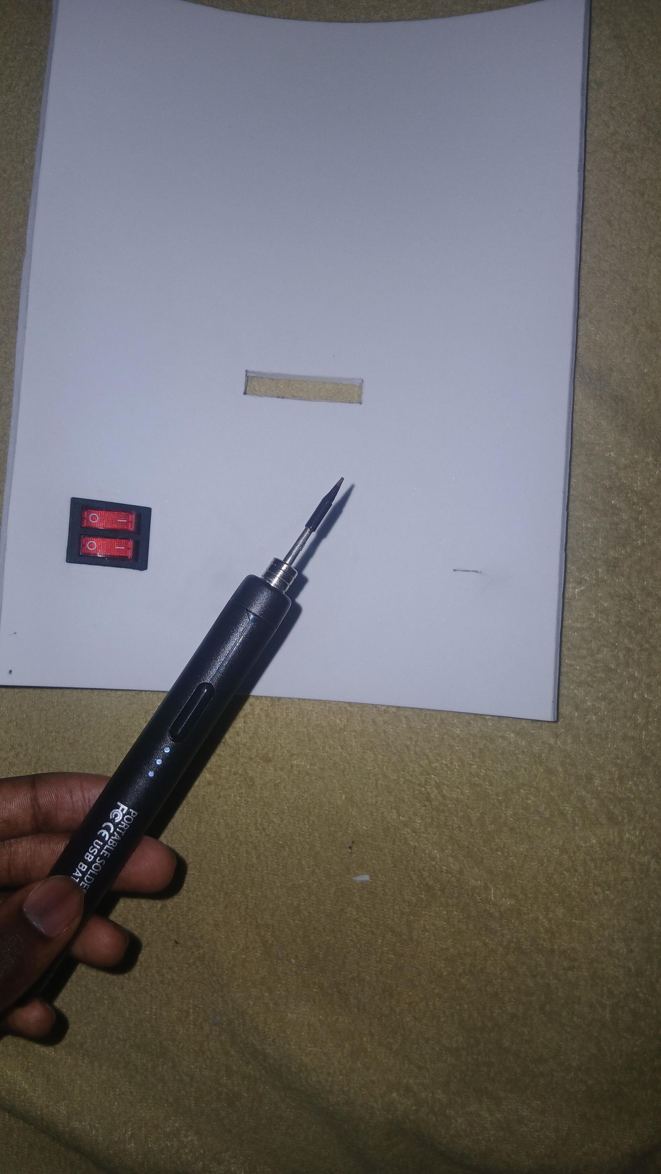
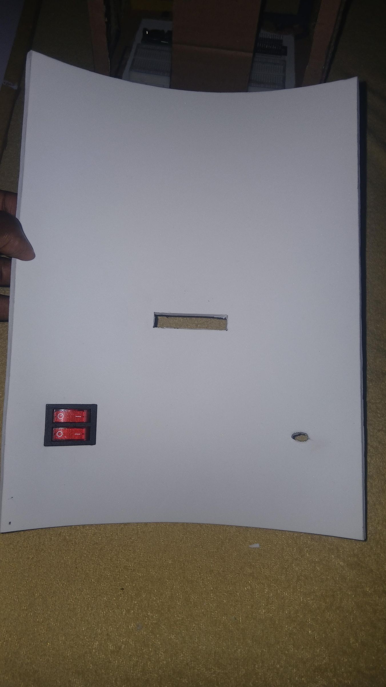
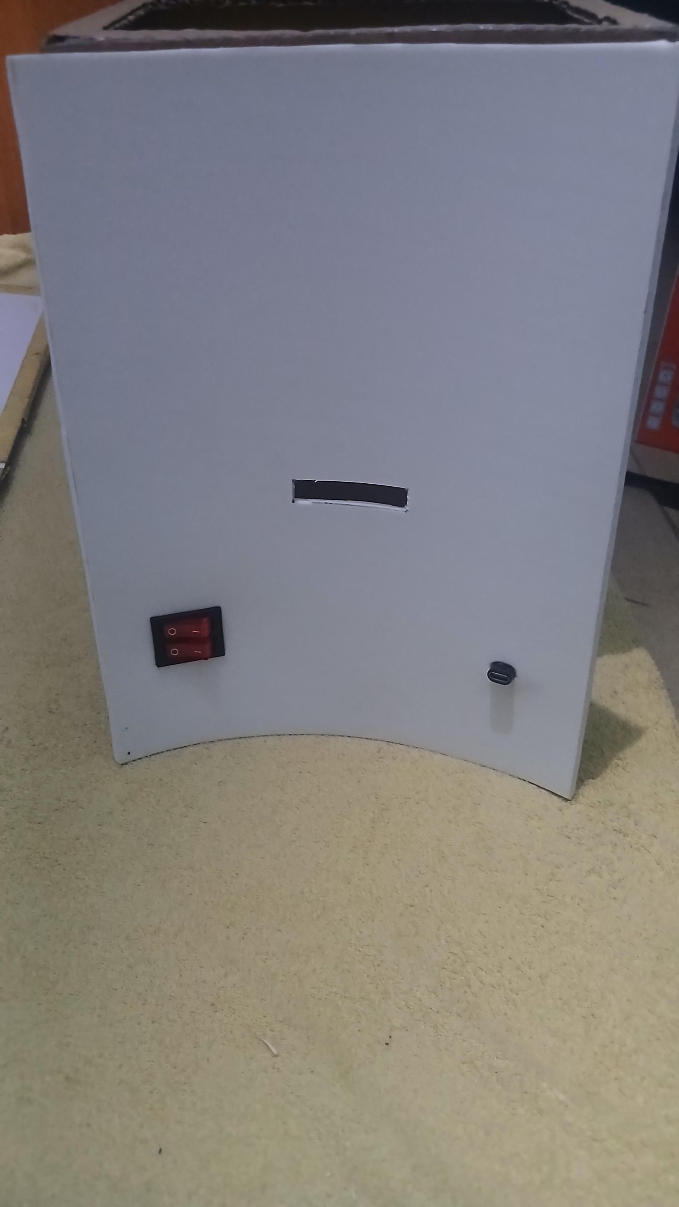
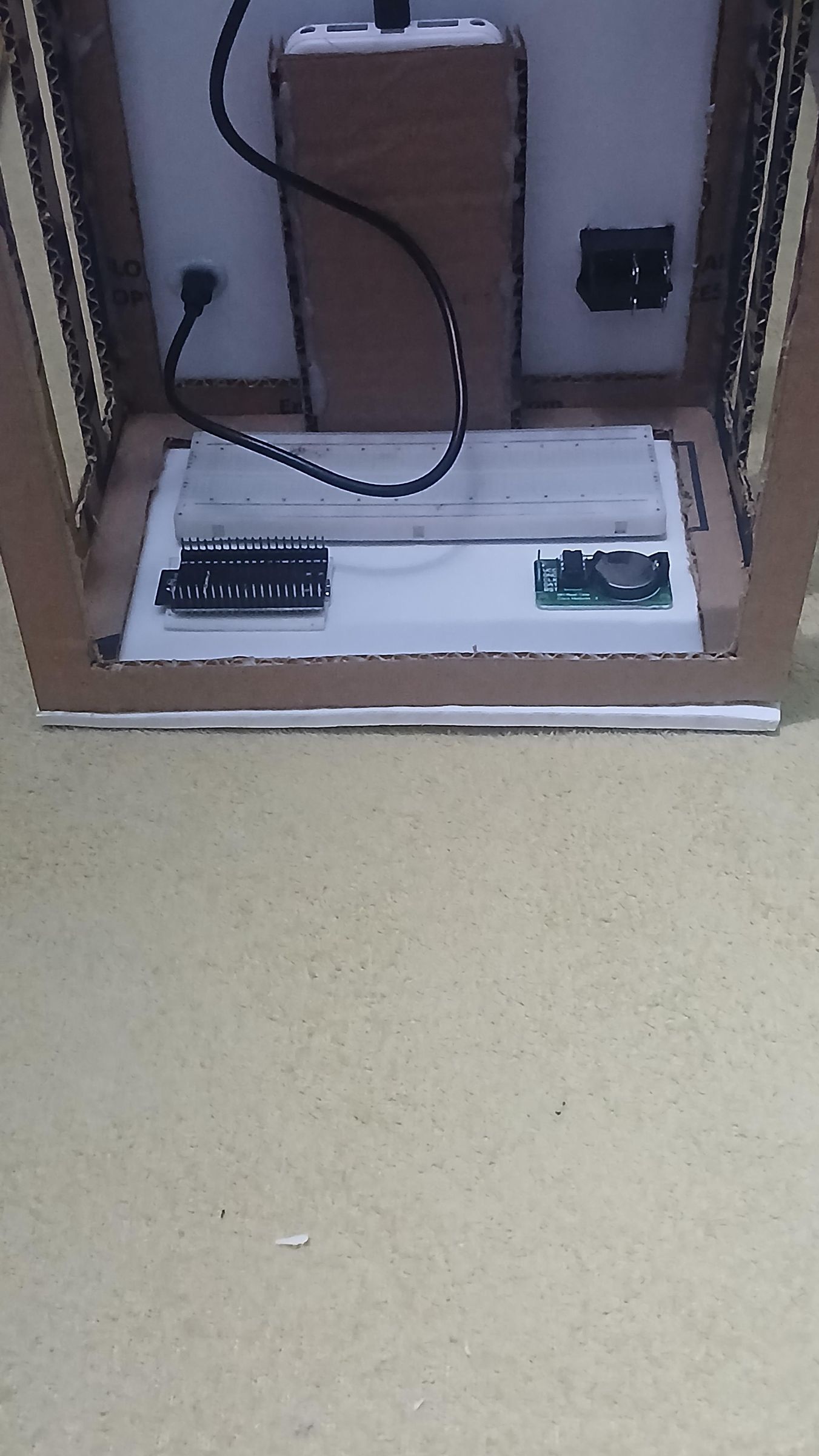
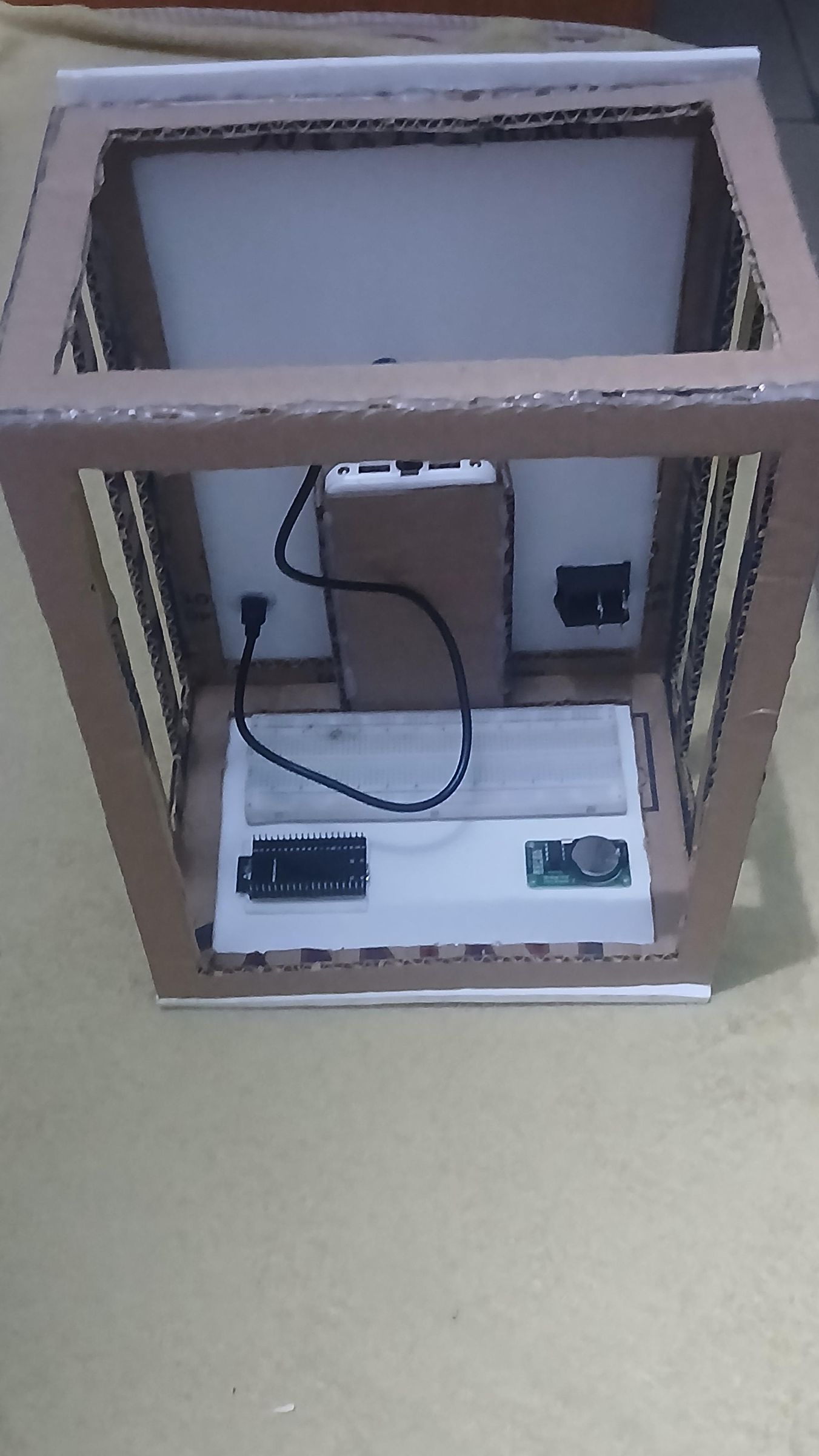
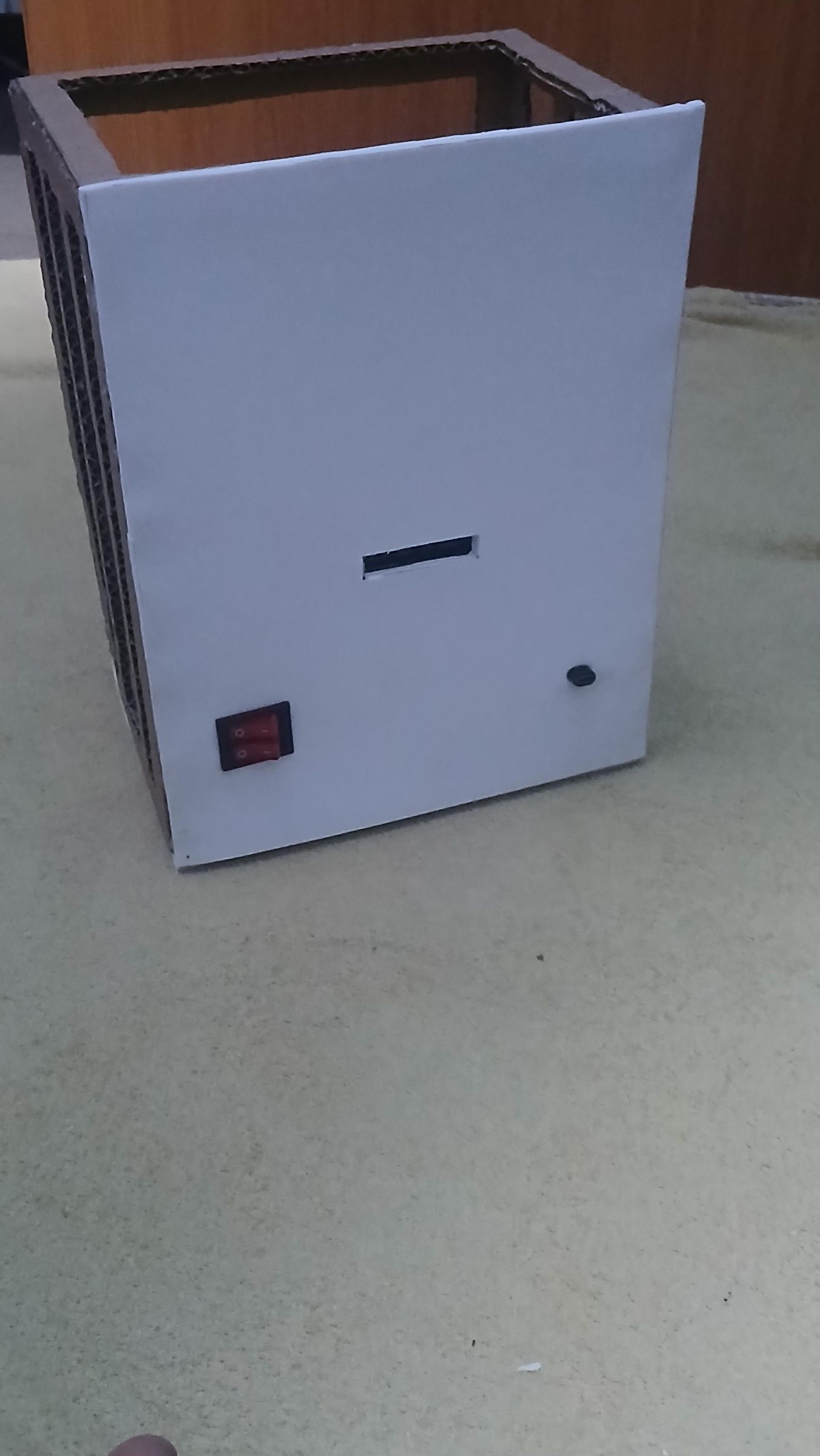
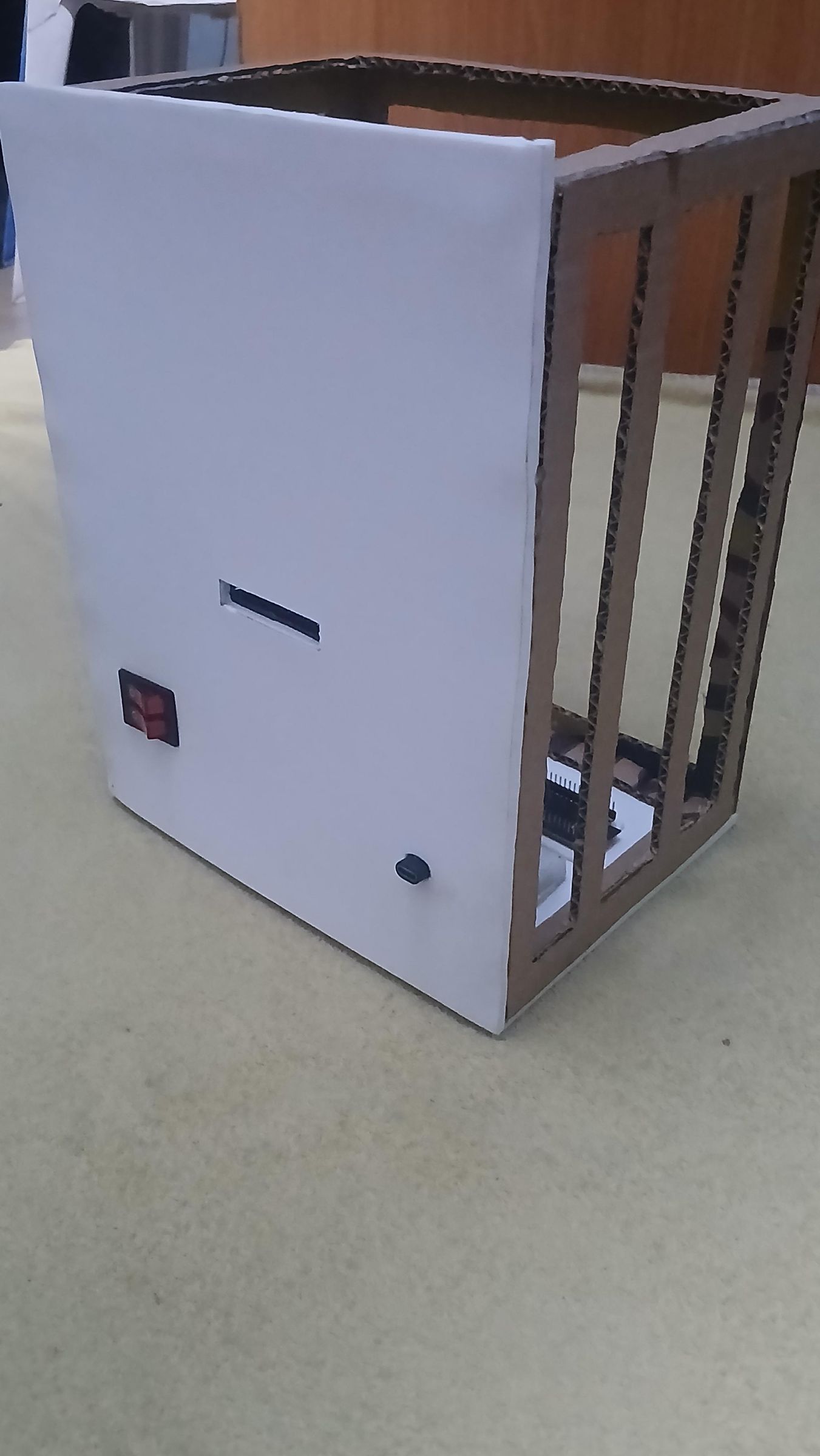
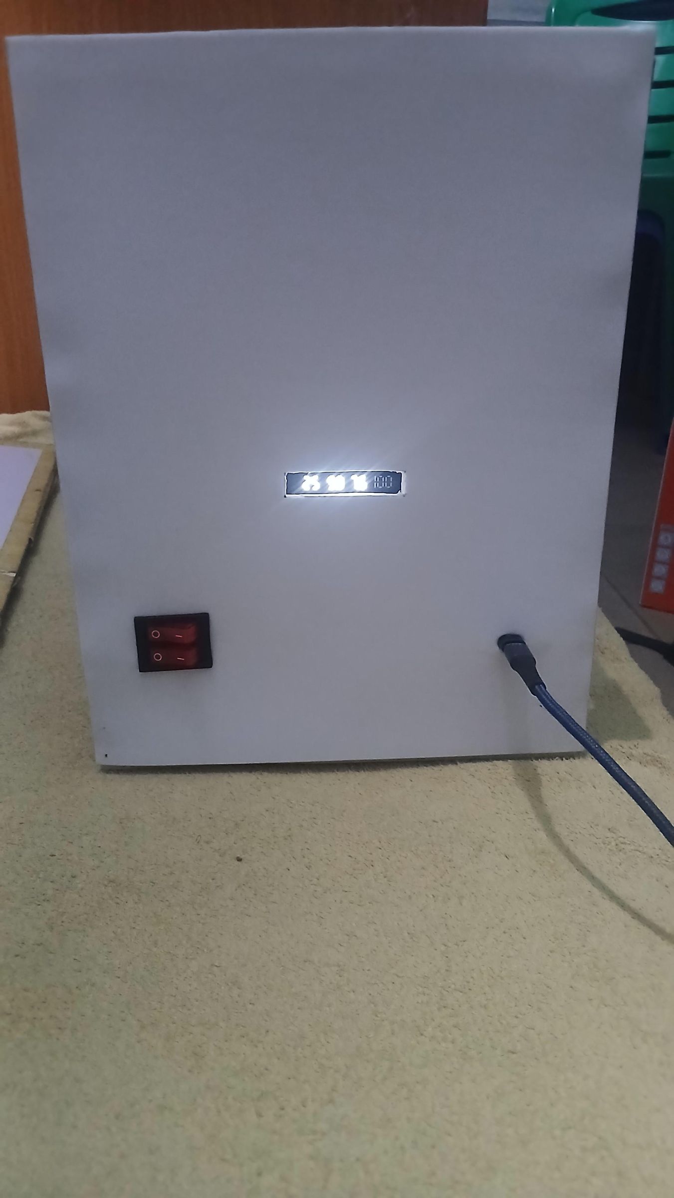
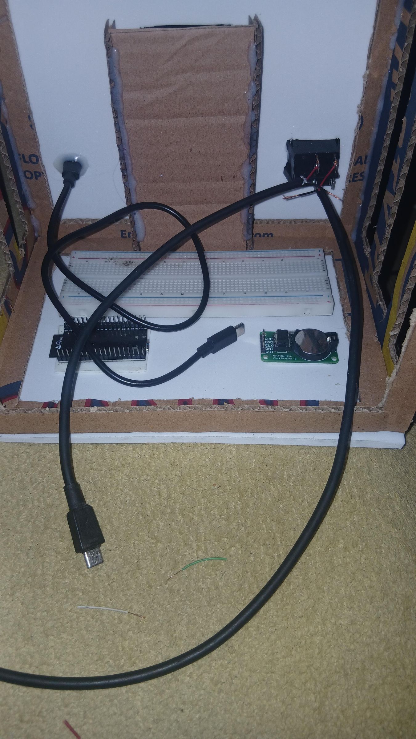
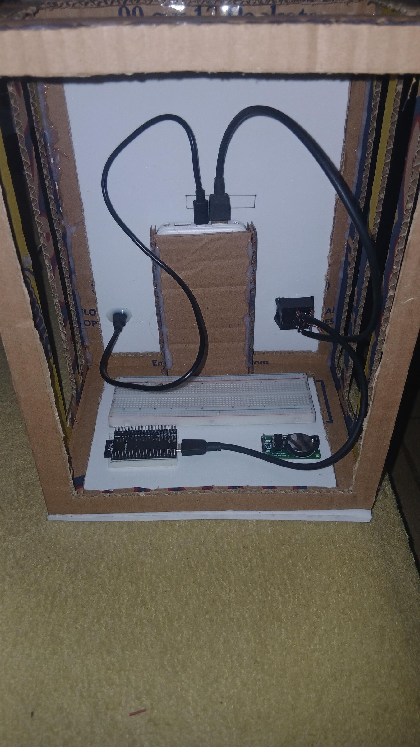
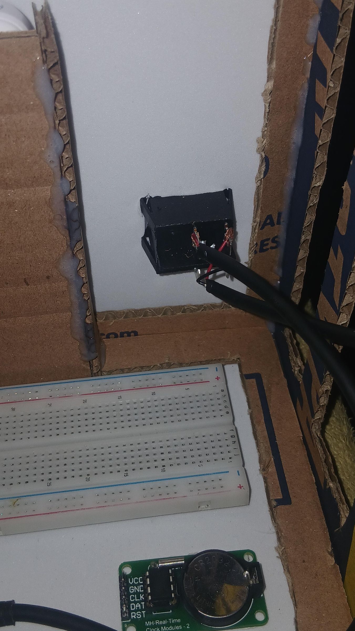
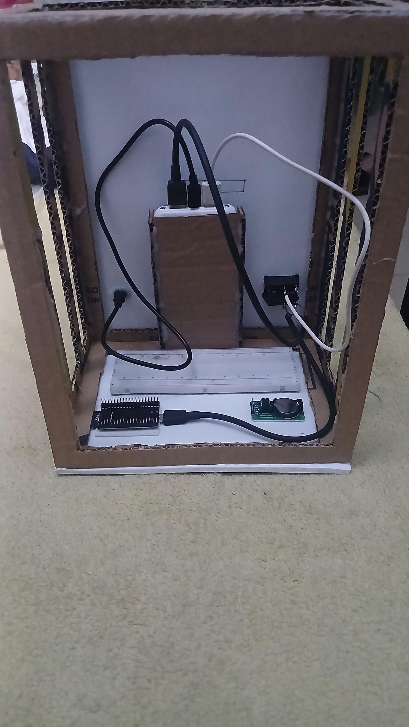
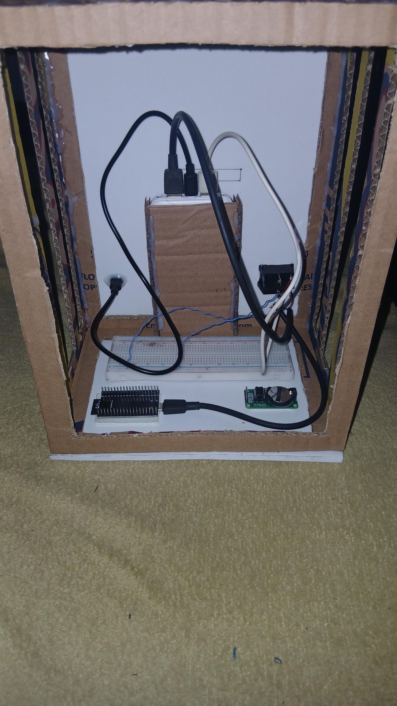
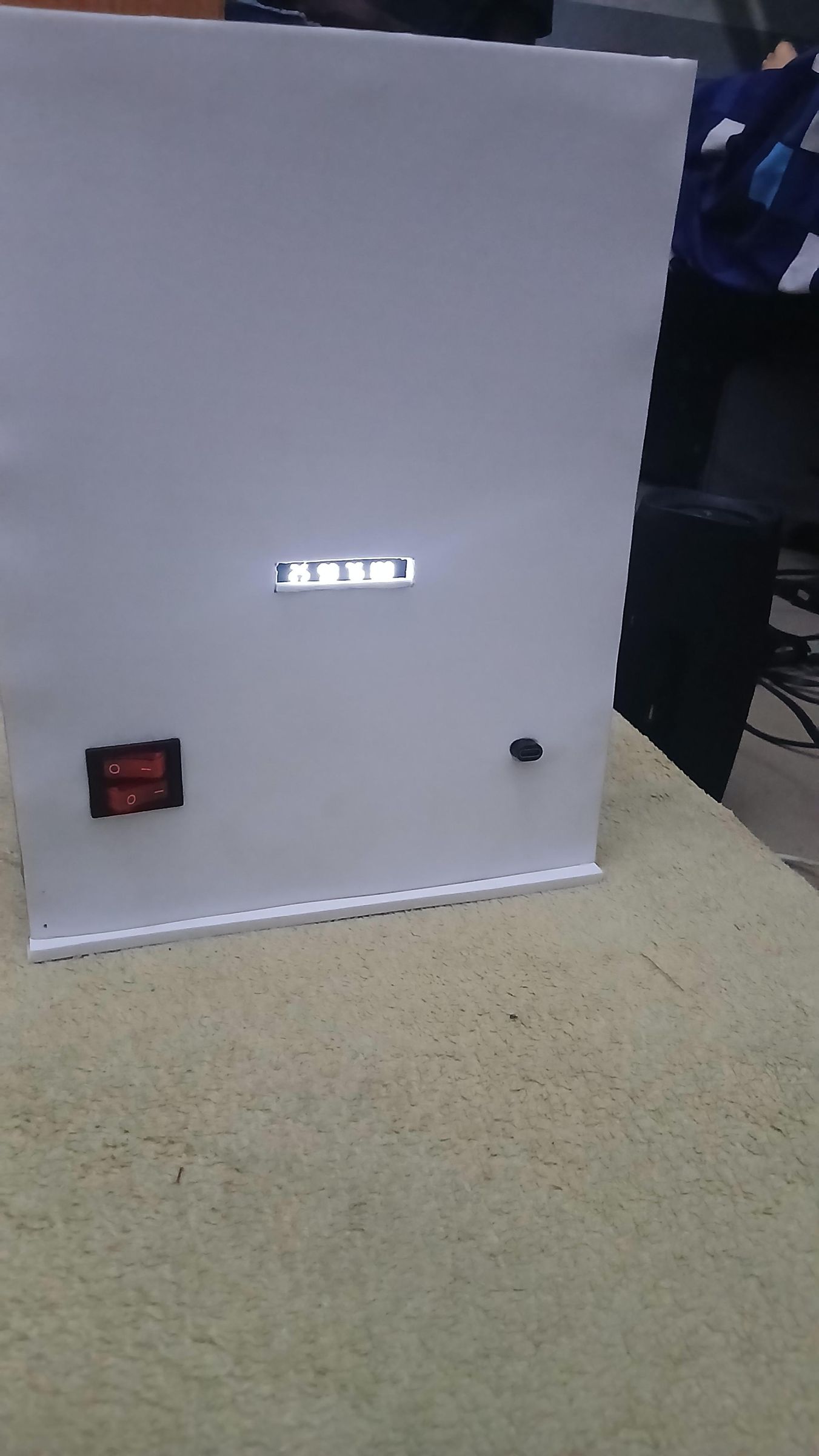
This step covers building the cardboard enclosure frame, paneling it in white foam-board, mounting the breadboard/ESP32/RTC, and then wiring up the back panel — the power switches, the battery percentage display window, and a USB-C extension cable so the power bank can be charged without opening the enclosure.
Outer frame dimensions:
- Front & Back: 22 × 28 cm
- Left & Right: 16 × 28 cm
- Top & Bottom: 16 × 22 cm
- Bracing: 1.5 cm width all round
- Gaps (left to right): 3, 4, 3 cm
Panel dimensions:
- Top & Bottom part: 16.8 x 22.7 cm
- Front–Back: 22.5 × 28.5 cm
- Left & Right: 17 × 29 cm
Power bank compartment dimensions:
- Sides: 2 × 13.5 cm
- Front: 7.5 × 10.5 cm
- Back: 7 × 14 cm
Back panel cutout positions:
- Back frame size: 22 × 28 cm
- Back panel size: 23 × 29 cm (1 cm larger each dimension — 0.5cm foam board overhang per side, so it caps over the frame)
What's happening in this step
- Cut and assemble the frame. Starting from the upcycled Cheese Balls cardboard, I cut the rectangular pieces that stack into the four corner struts plus top and bottom — these glue into an open skeleton frame.
- Panel it in white foam-board. Each side gets a cut sheet of white foam-board glued onto the cardboard frame for a clean finish.
- Mount the breadboard, ESP32, and DS3231 RTC. All three are fixed to the white interior base with double-sided tape — the foundation for the rest of the wiring.
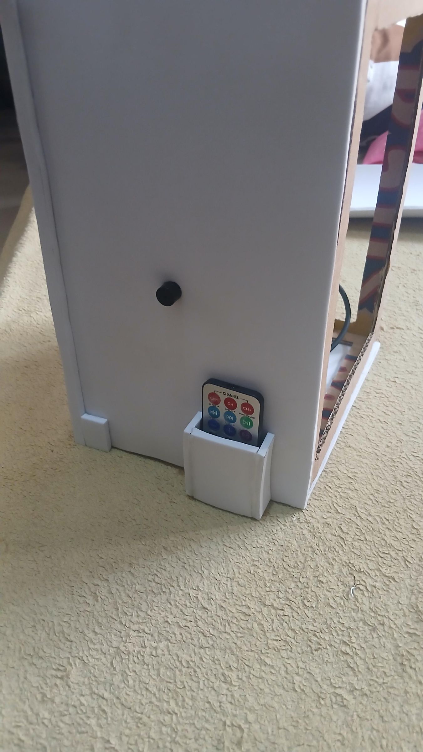
- House the power bank separately. The power bank sits in its own small cardboard sleeve inside the enclosure, positioned so its battery-percentage display lines up with a cutout window in the back panel.
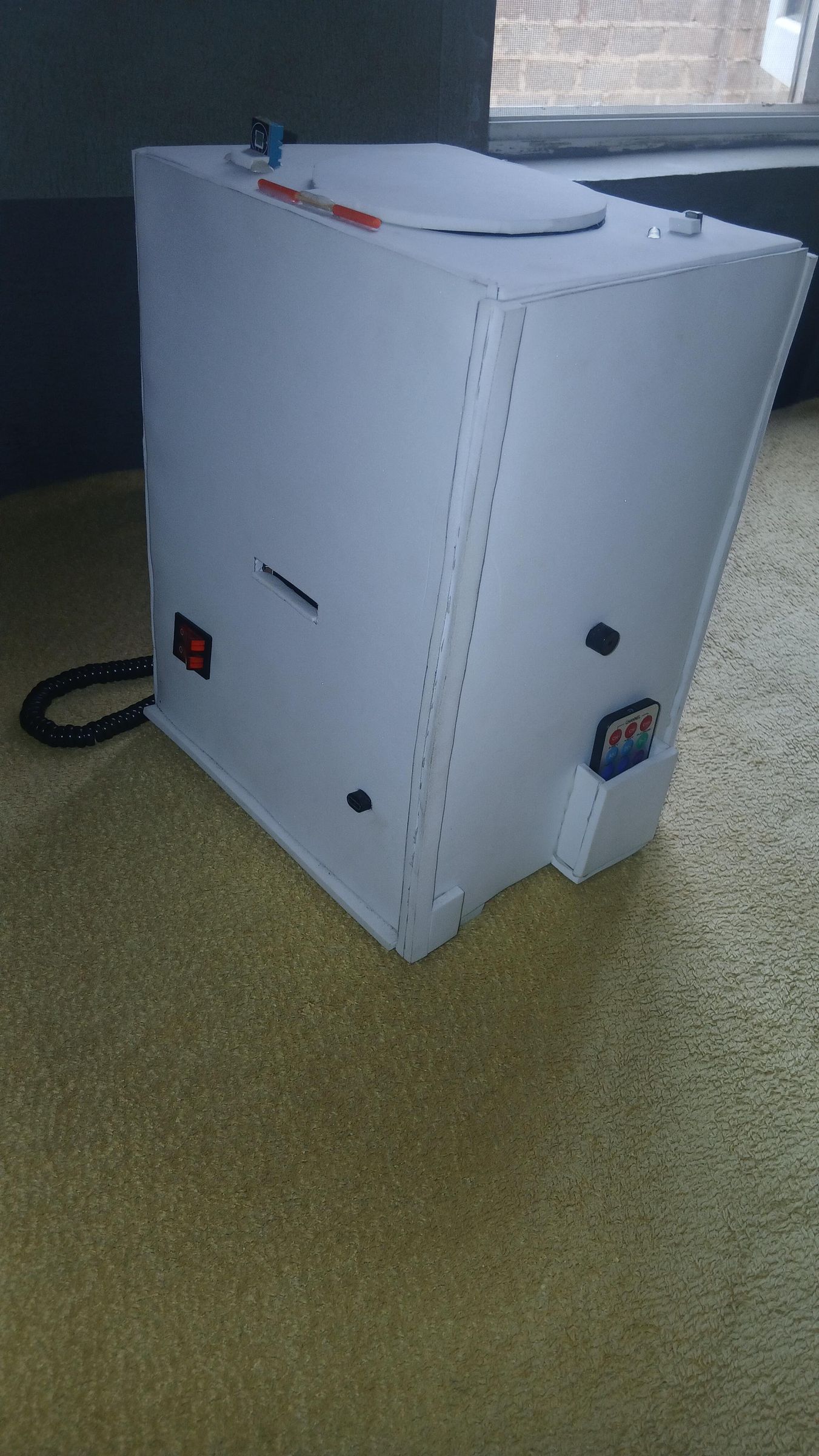
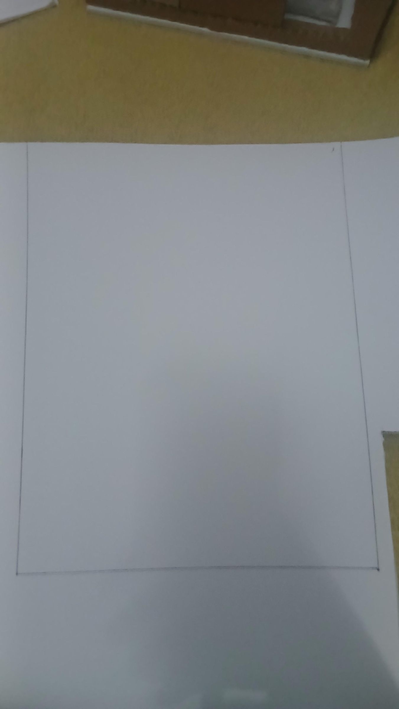
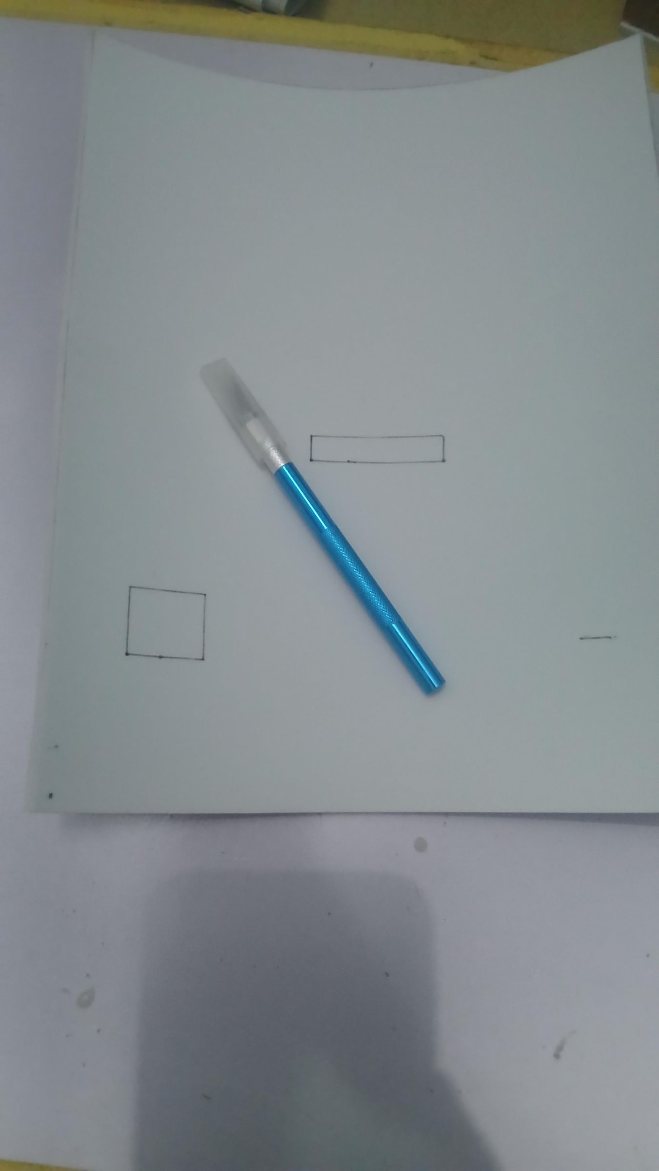
- Lay out and cut the back panel. Following the actual enclosure design drawing, I marked and cut a window for the percentage display, a cutout for the USB-C extension cable, and a mounting spot for the double rocker switch.
- Mount the double switch and USB-C extension on the back panel. The switch fits into its cutout; the USB-C extension cable plugs straight into the power bank's port and feeds out through the panel — no soldering required.
- Tie both of the power bank's USB outputs to common ground. The power bank has two USB output ports. Both are wired with a blue jumper down to the breadboard's ground rail, so every component sharing that ground reference stays consistent regardless of which output port is feeding power at the time.
- Route the two power cables. Two cables run from the back panel down to the breadboard area:
- White cable → servo motor (controlled by one pole of the double switch)
- Black cable → ESP32 (the main system power, controlled by the other pole)
- Close up and check the back panel from outside. With everything wired, the back panel shows the battery percentage glowing through its window, the double switch, and the USB-C charging cable — all accessible without opening the enclosure.
Wiring the Vital-Sign Sensors, Buzzer, and IR Receiver
.png)
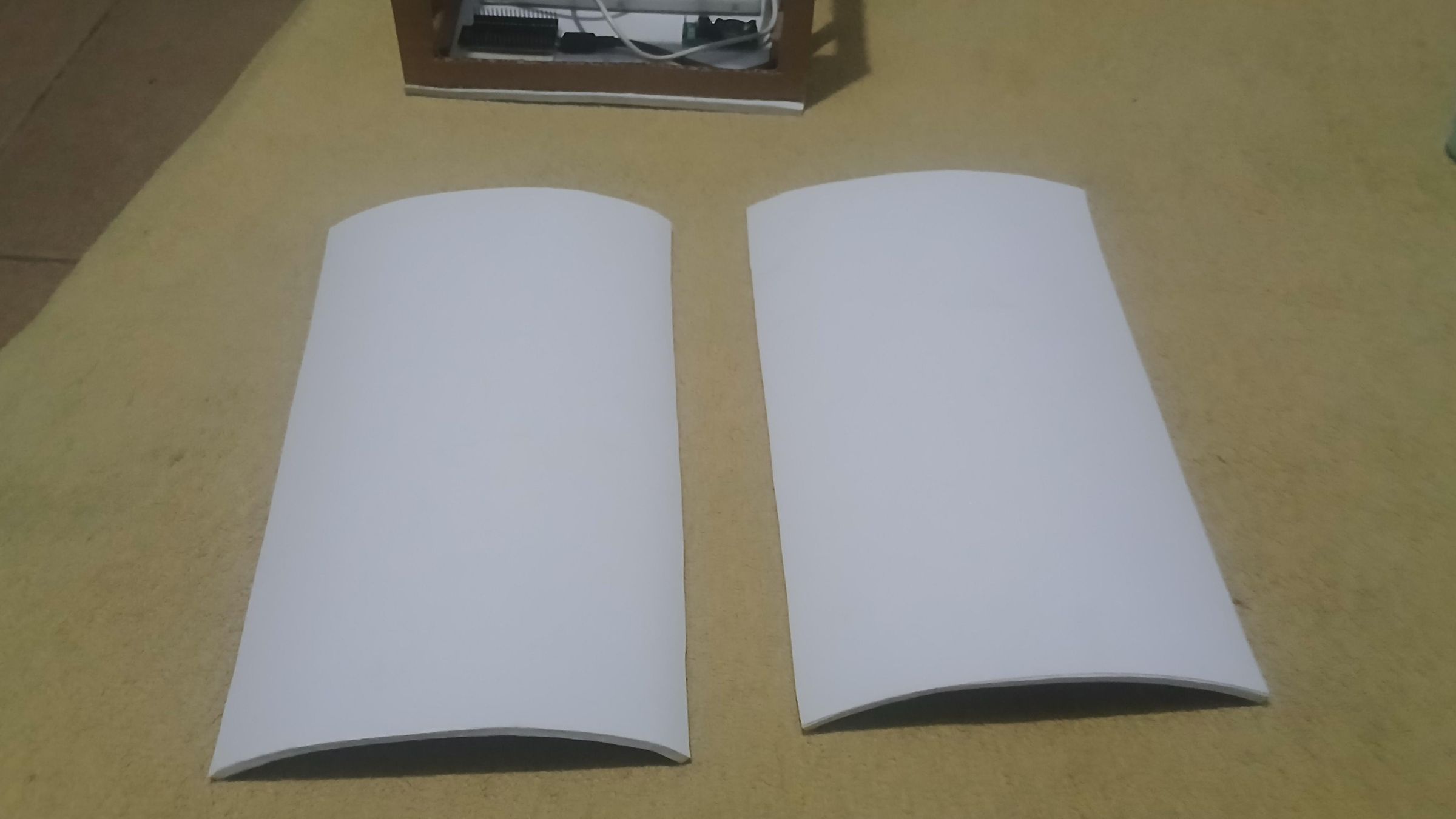
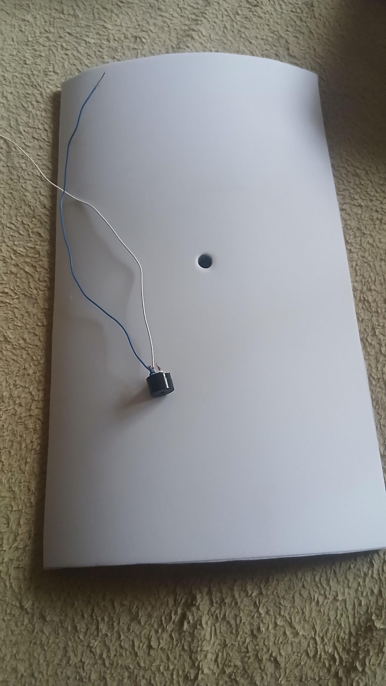
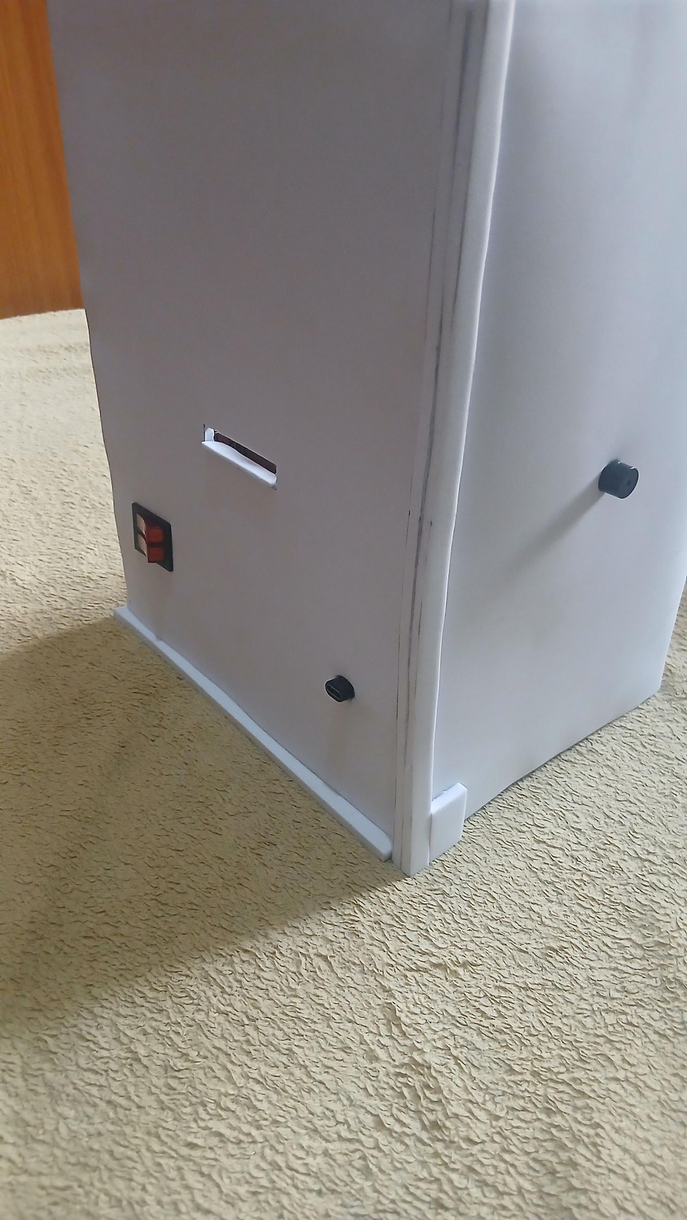
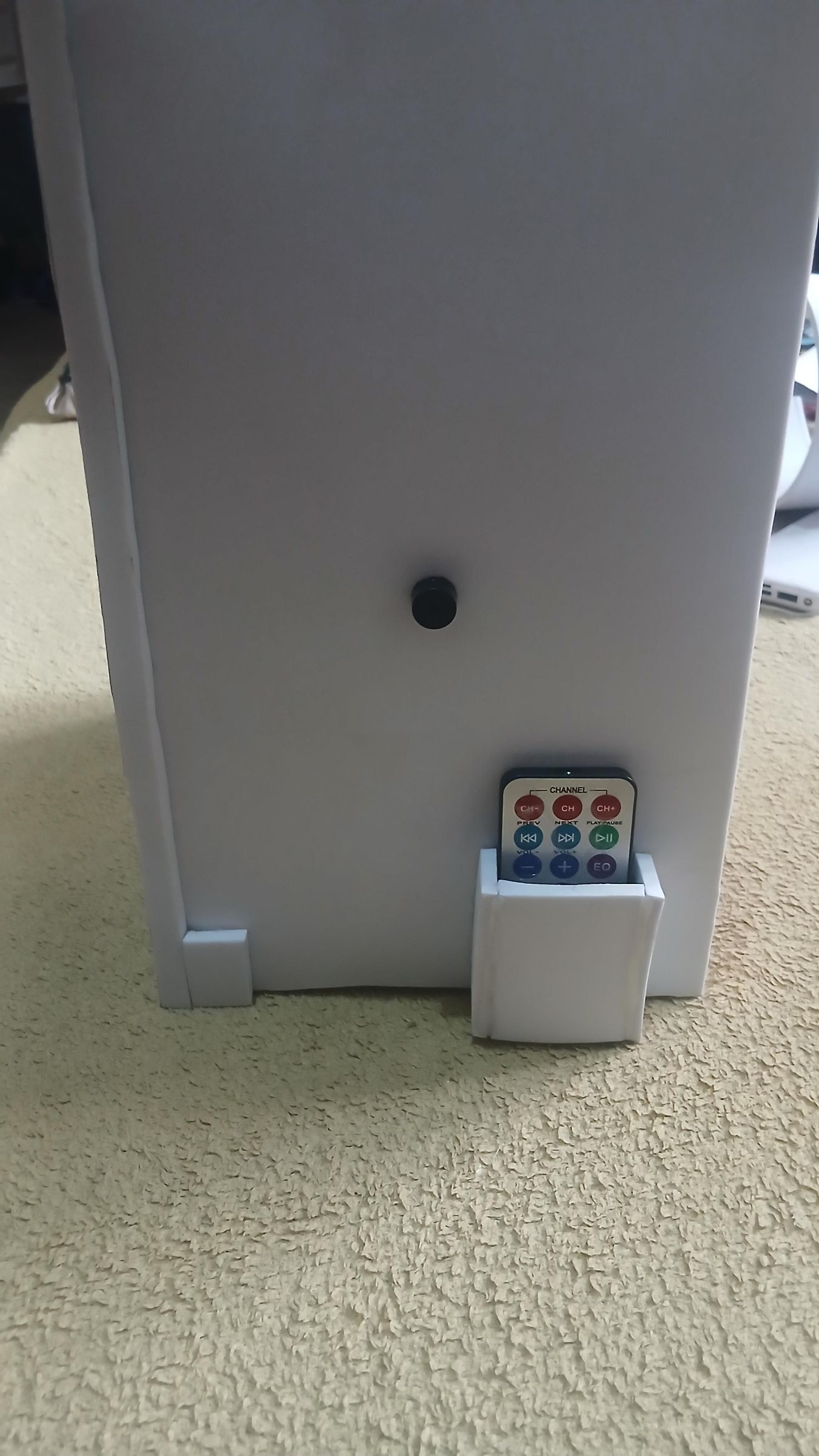
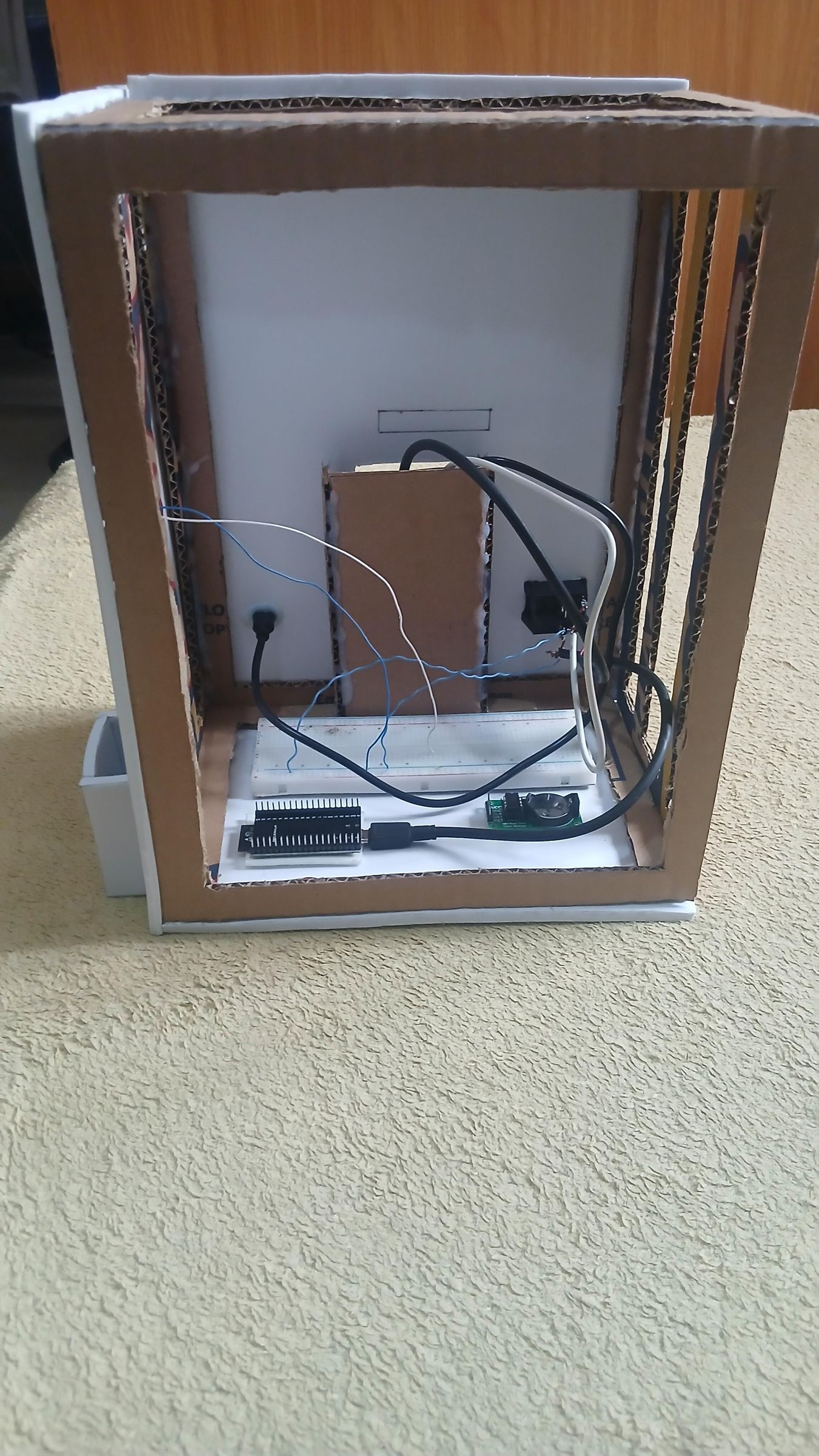
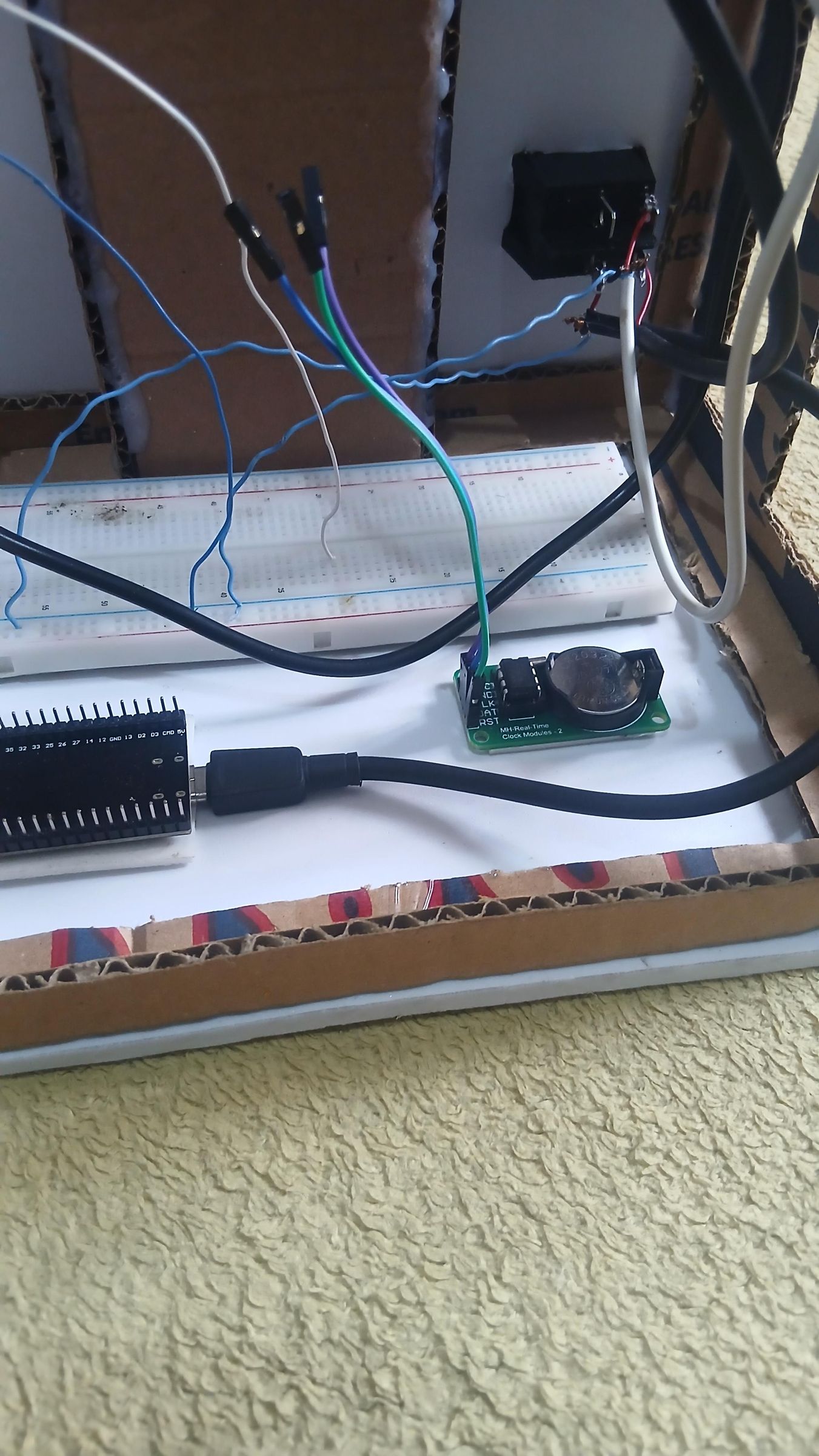
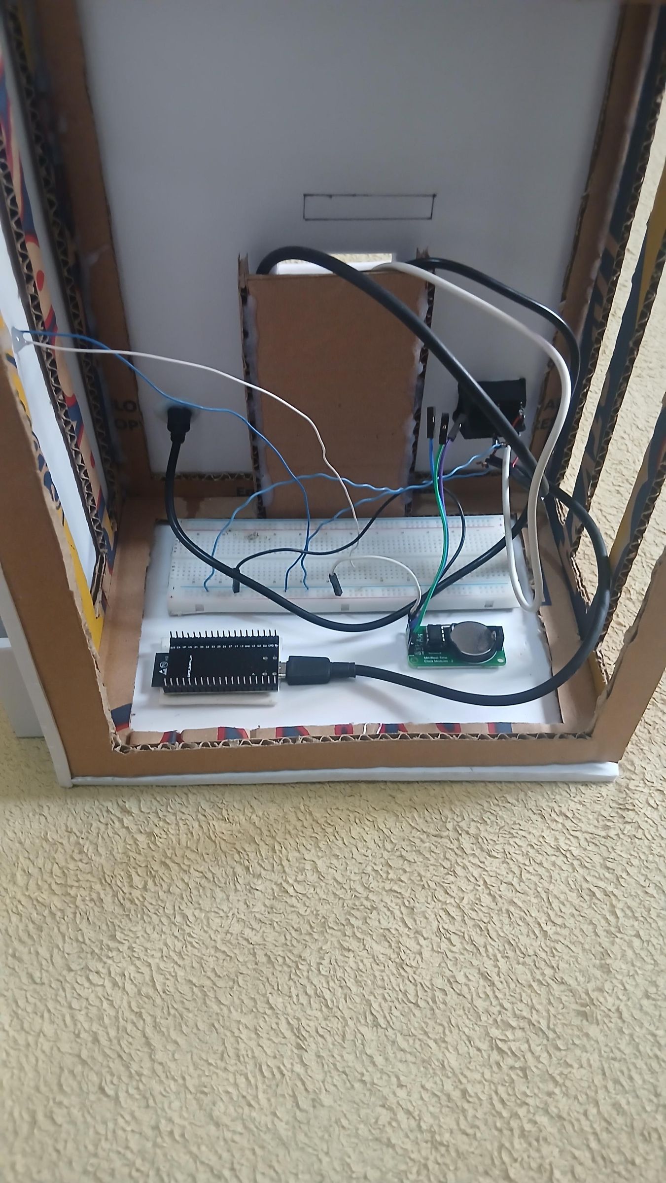

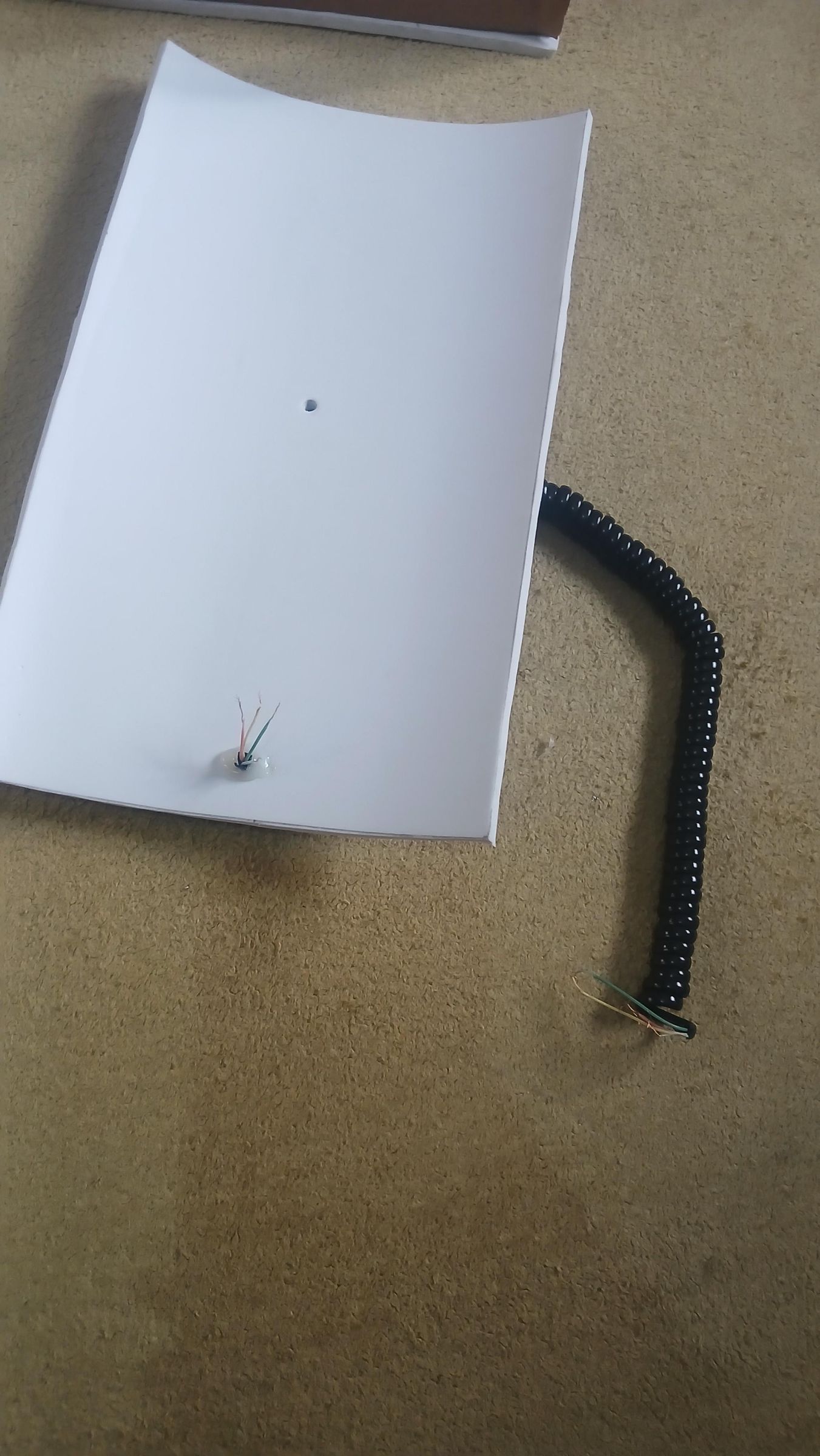
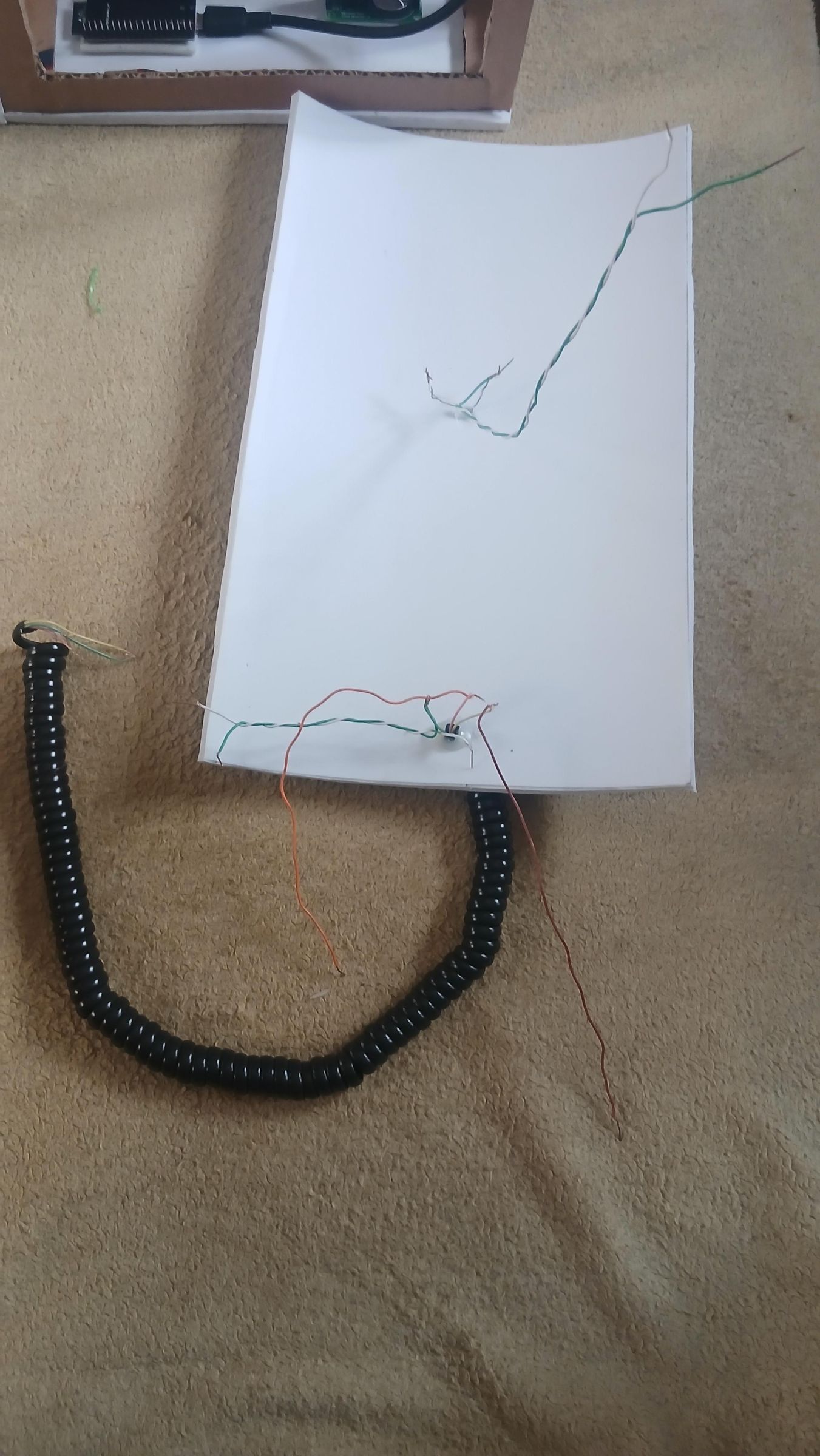
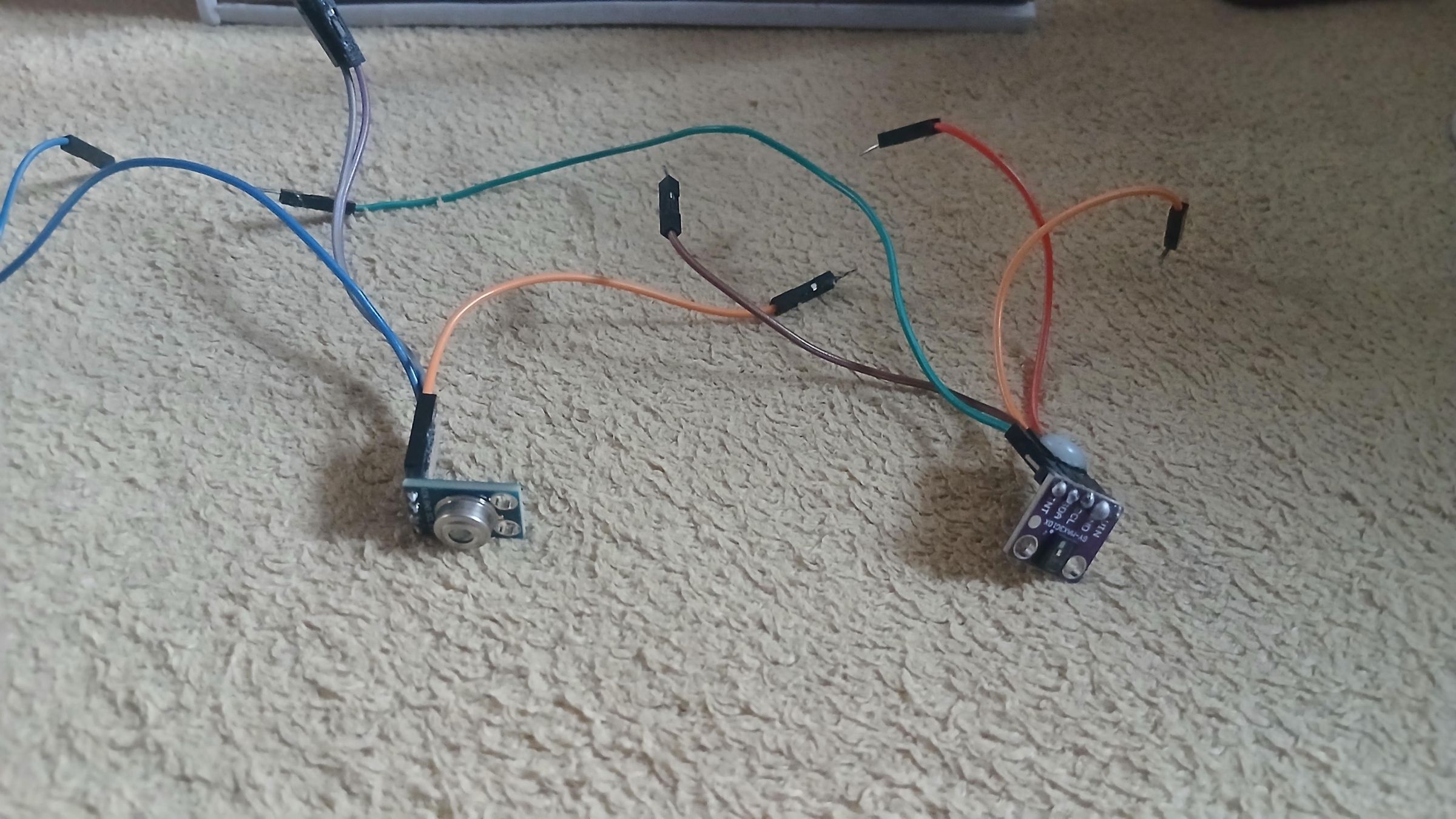
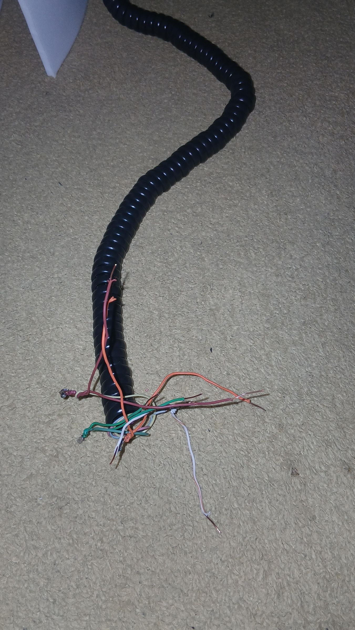
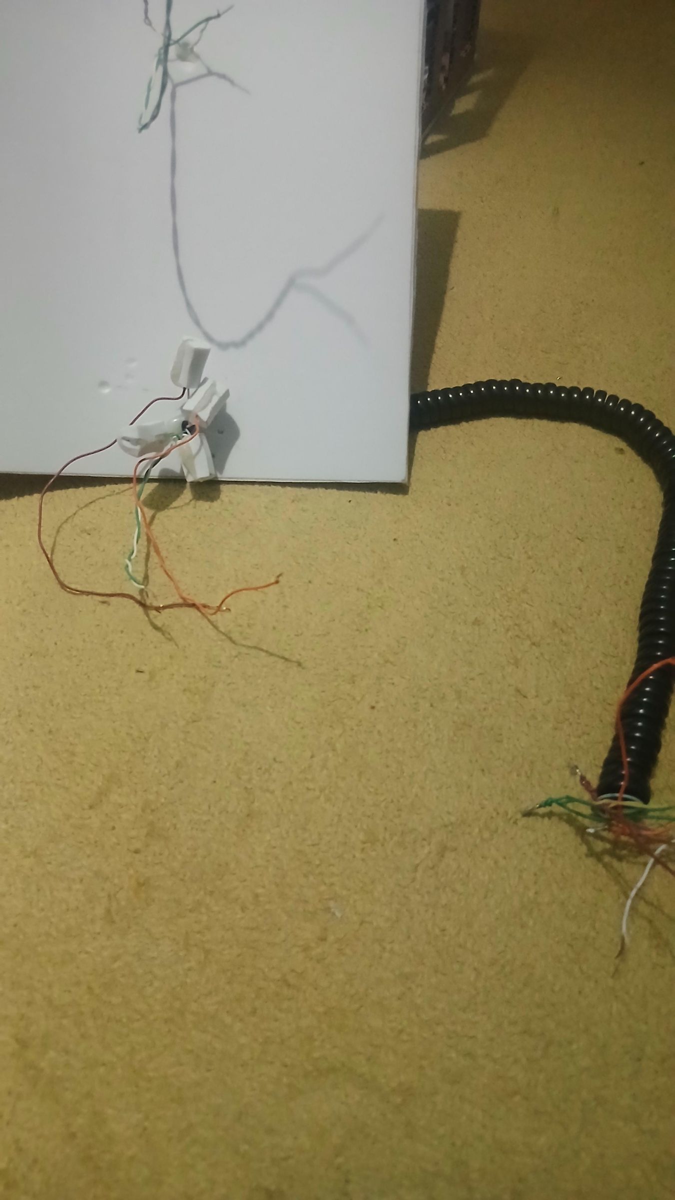
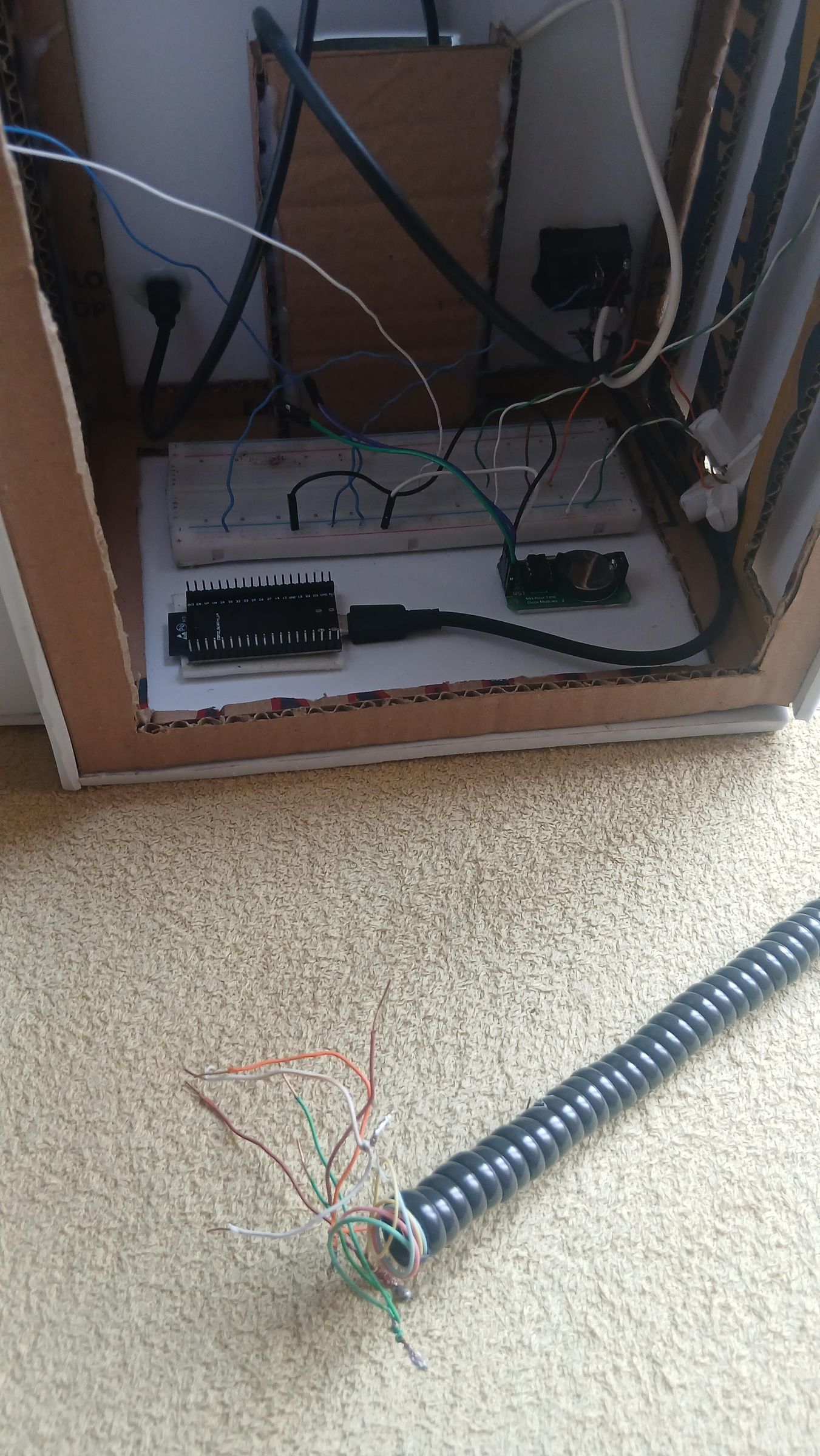
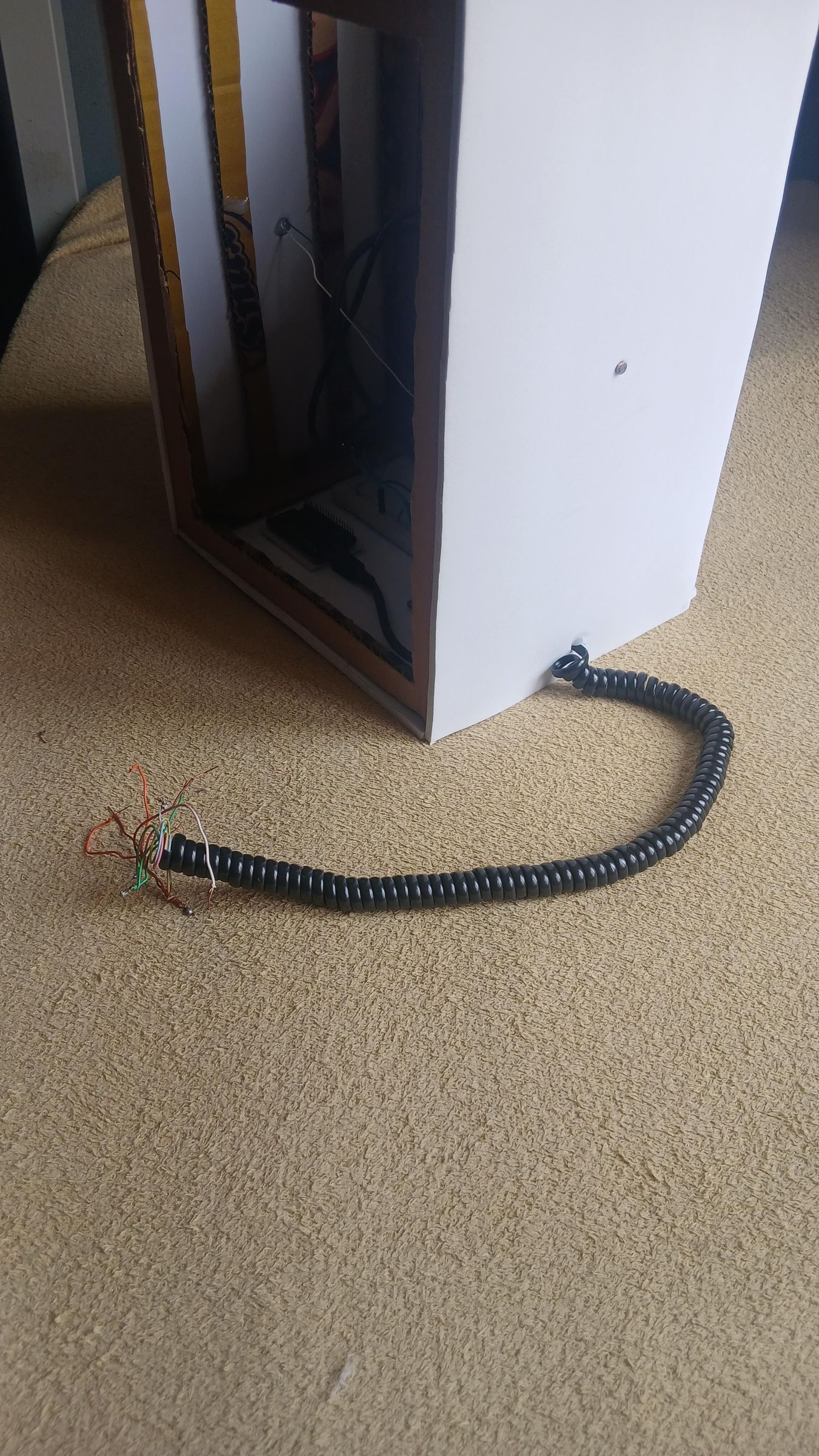
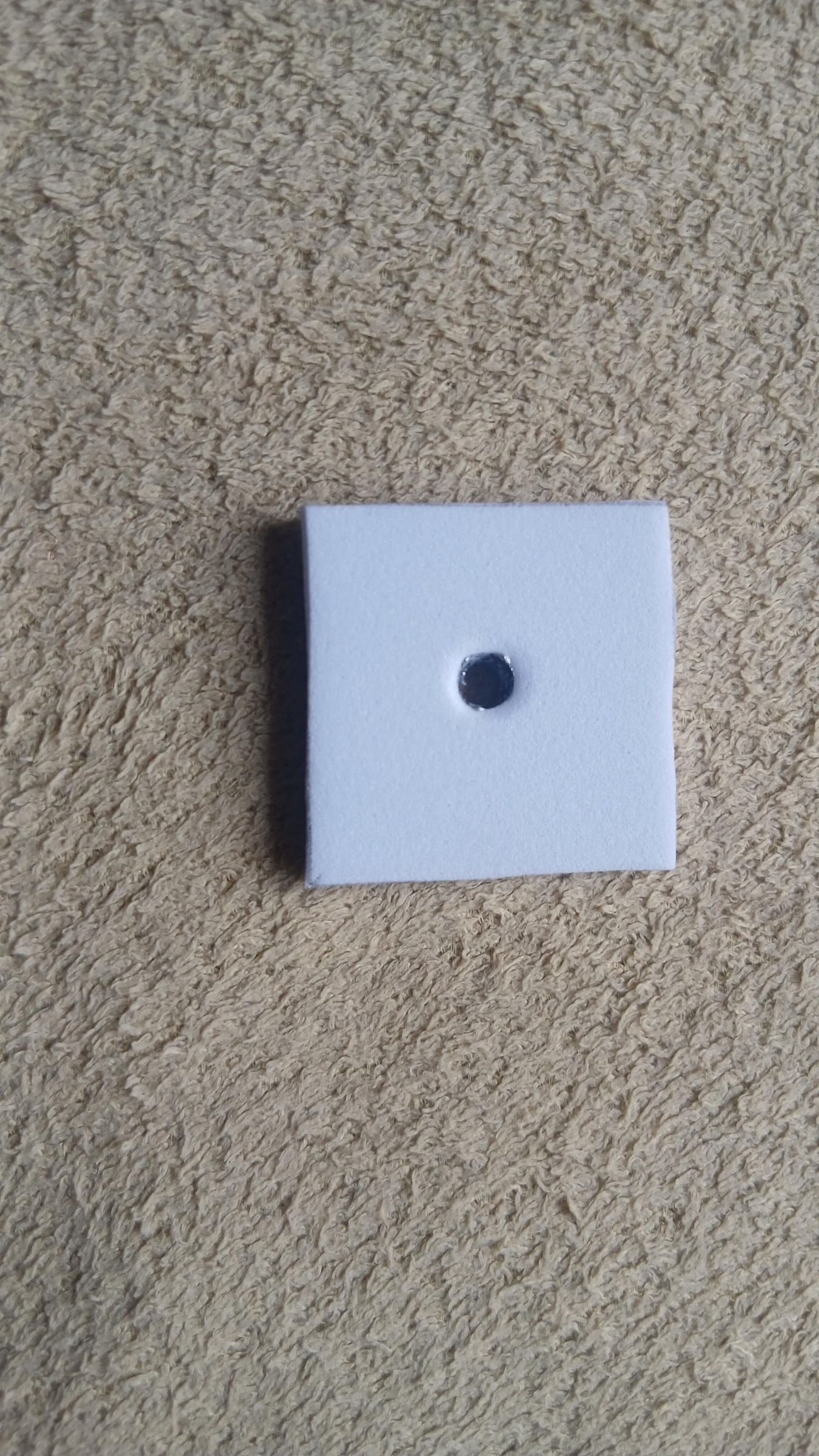
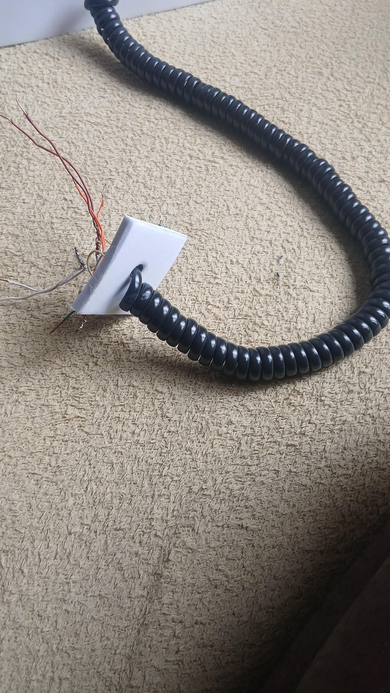
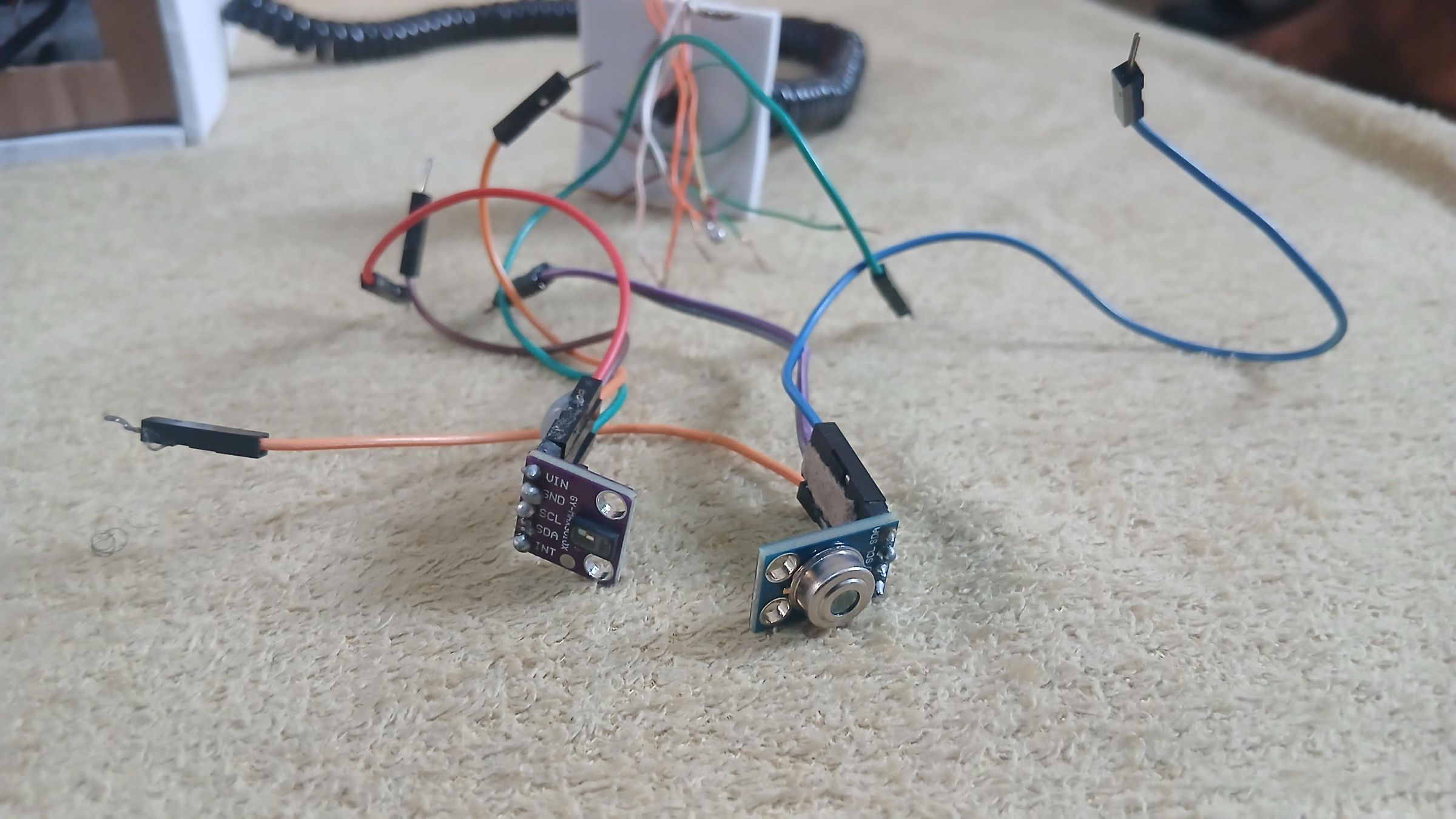
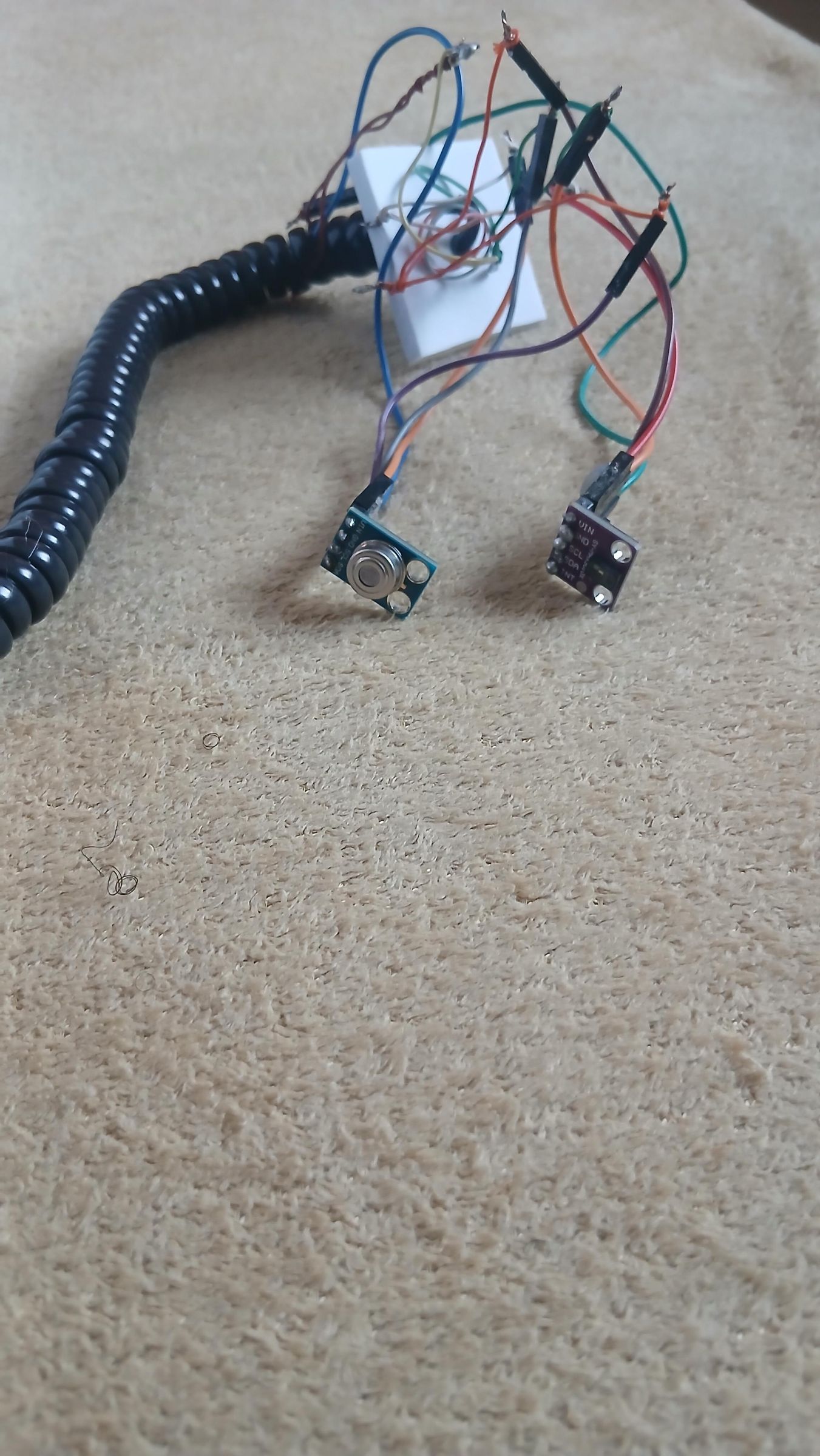
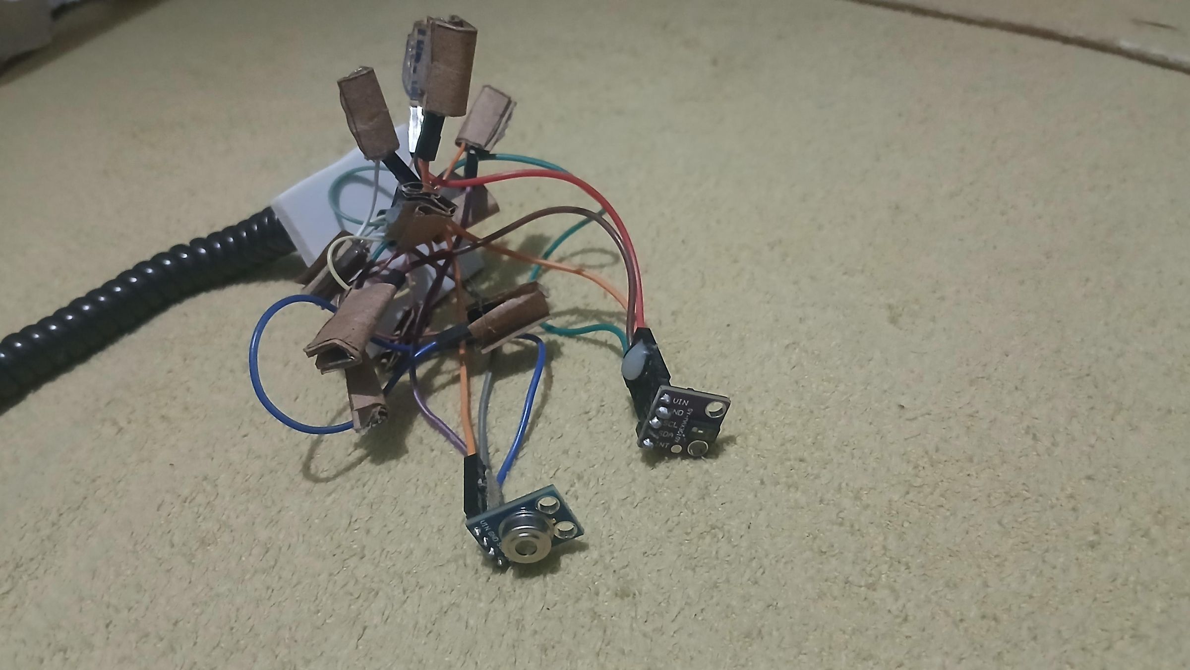
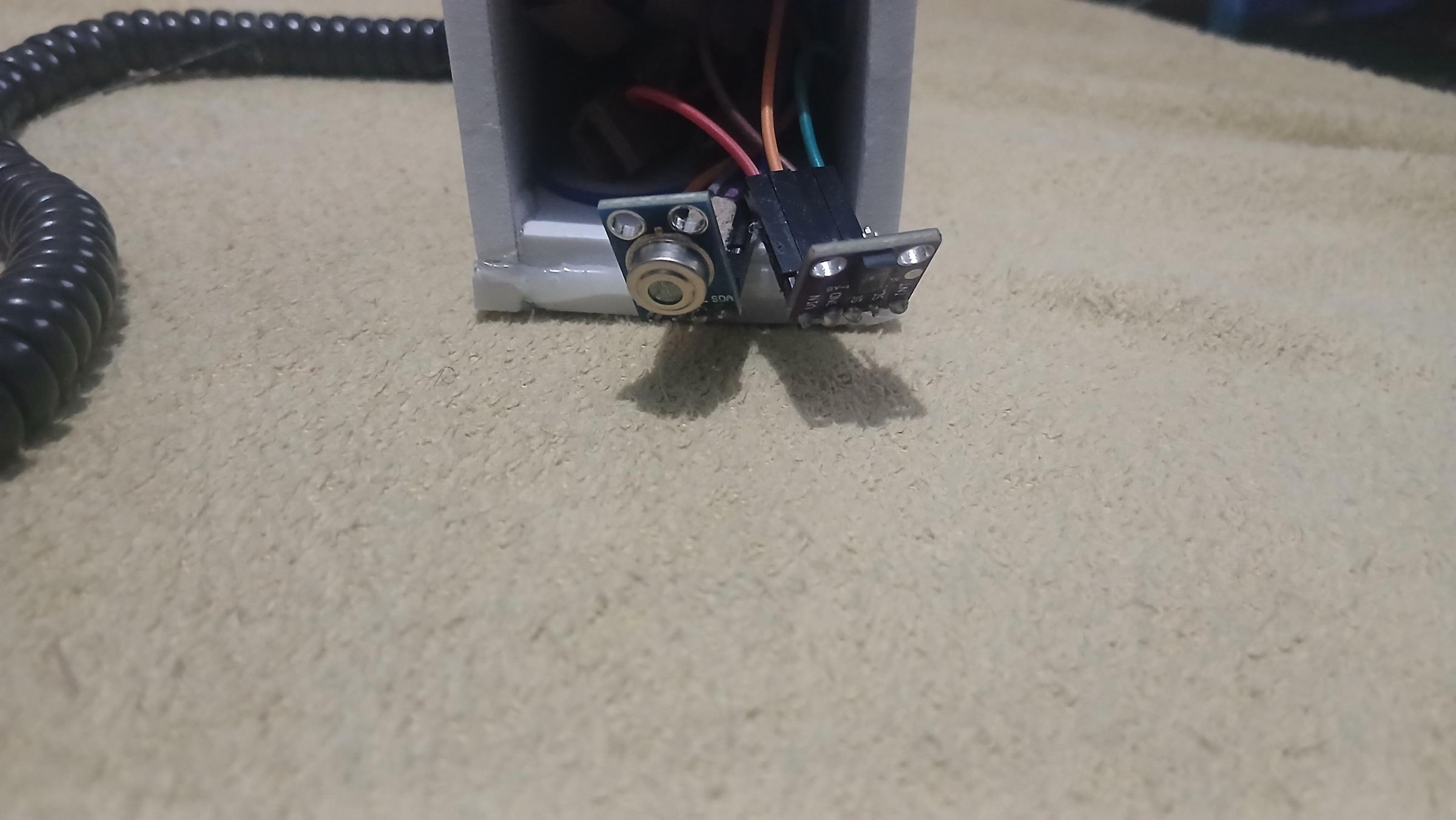
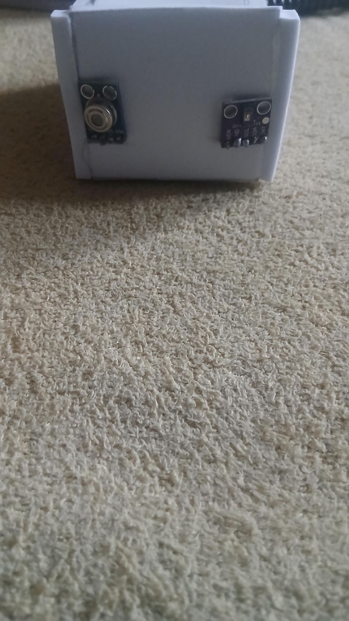
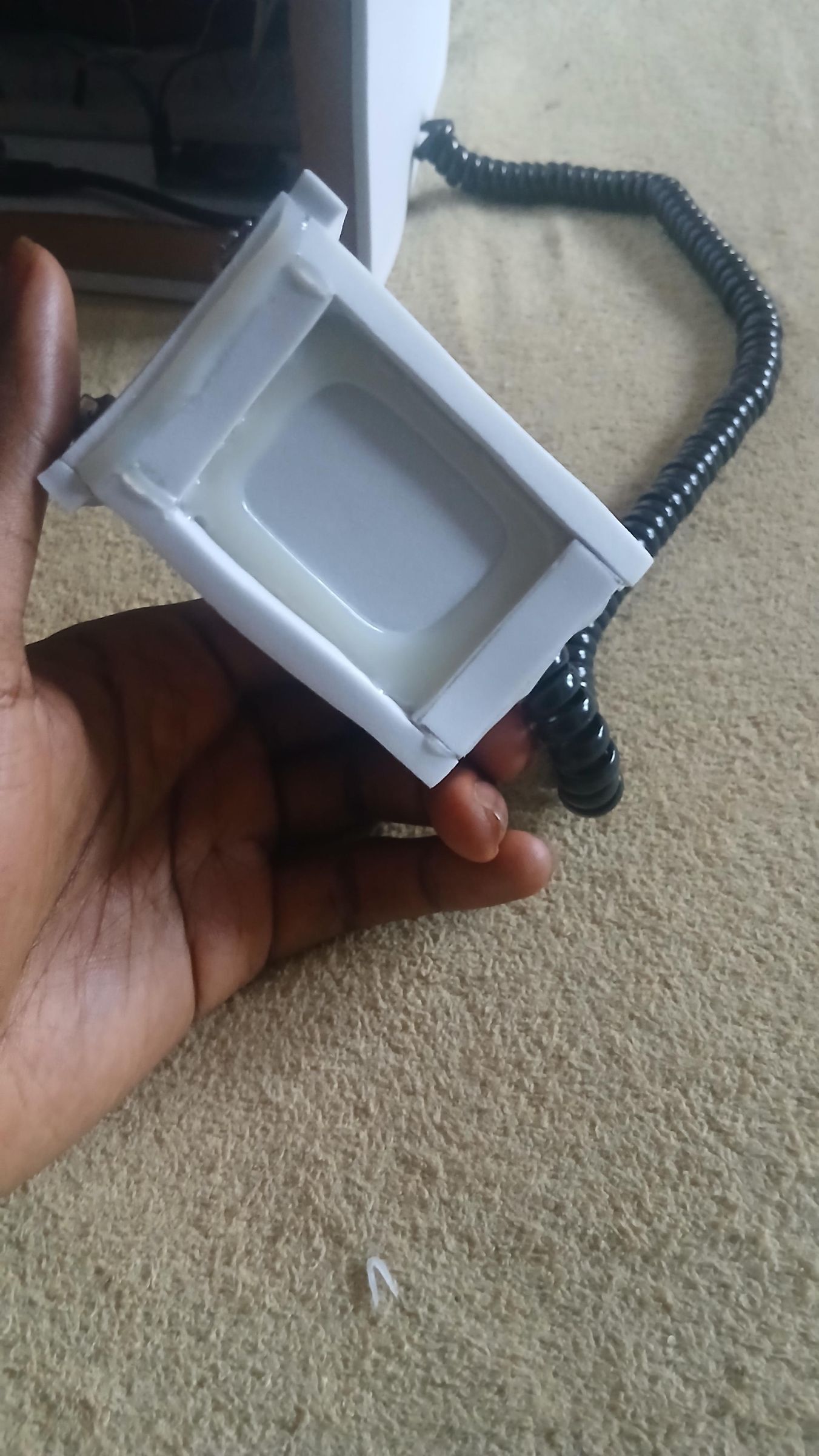
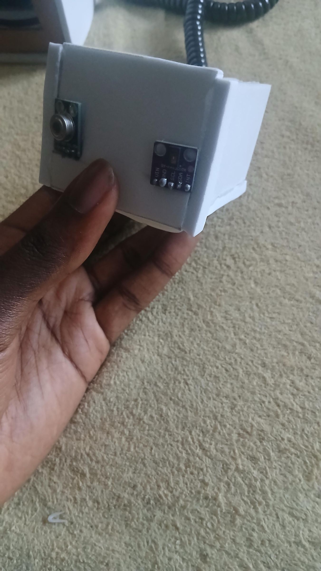
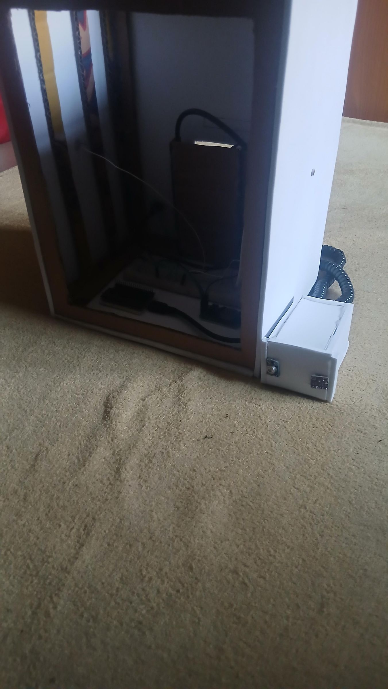
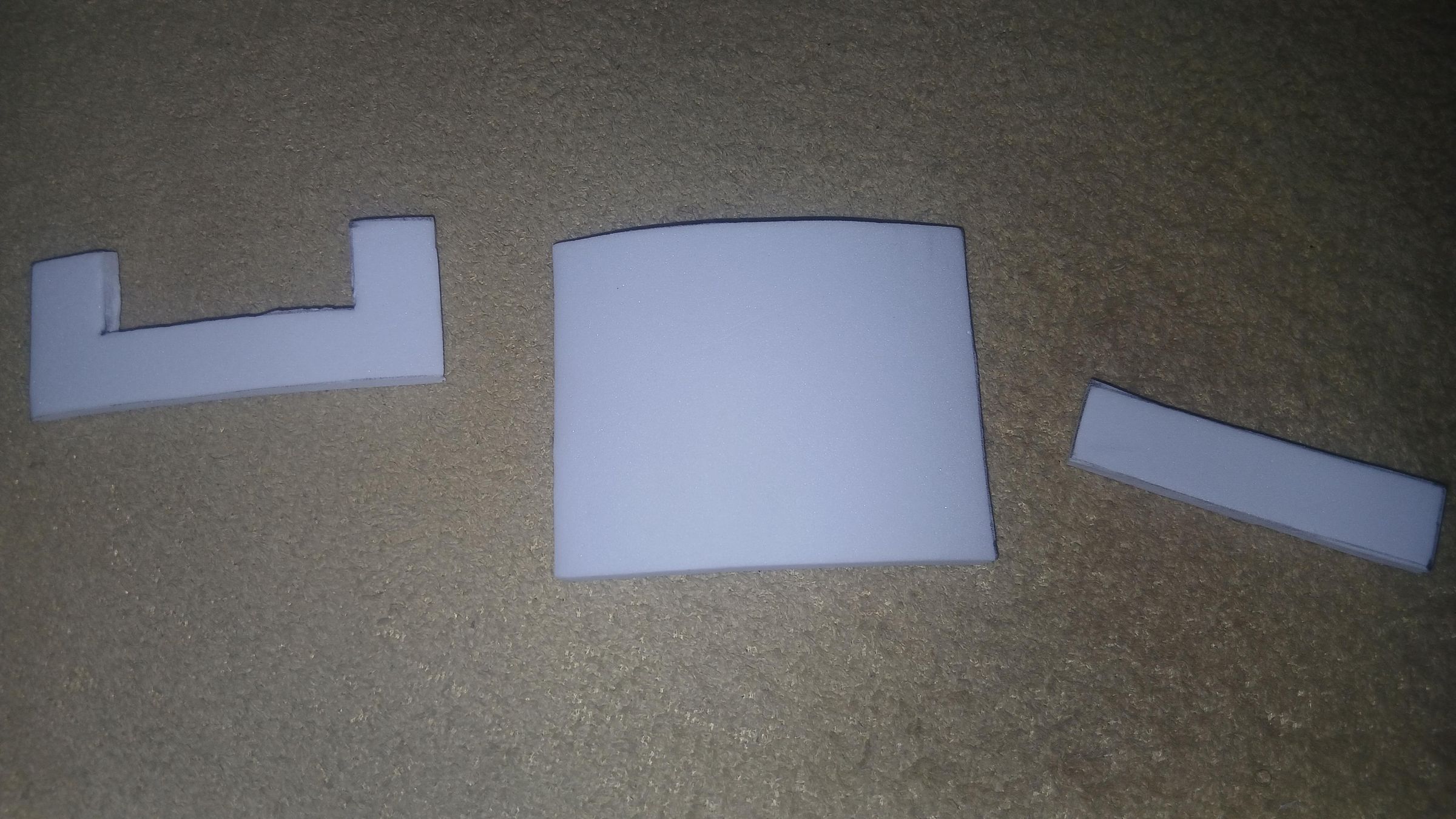
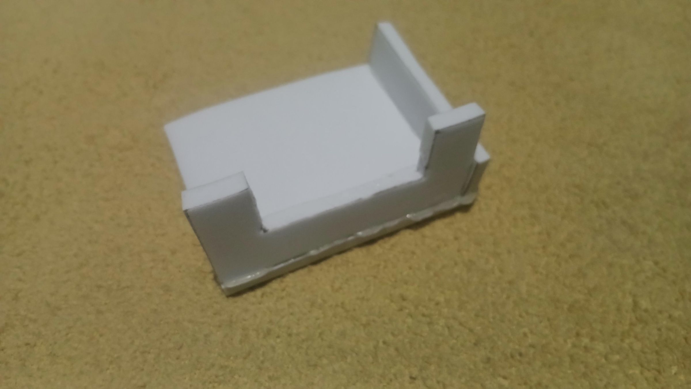
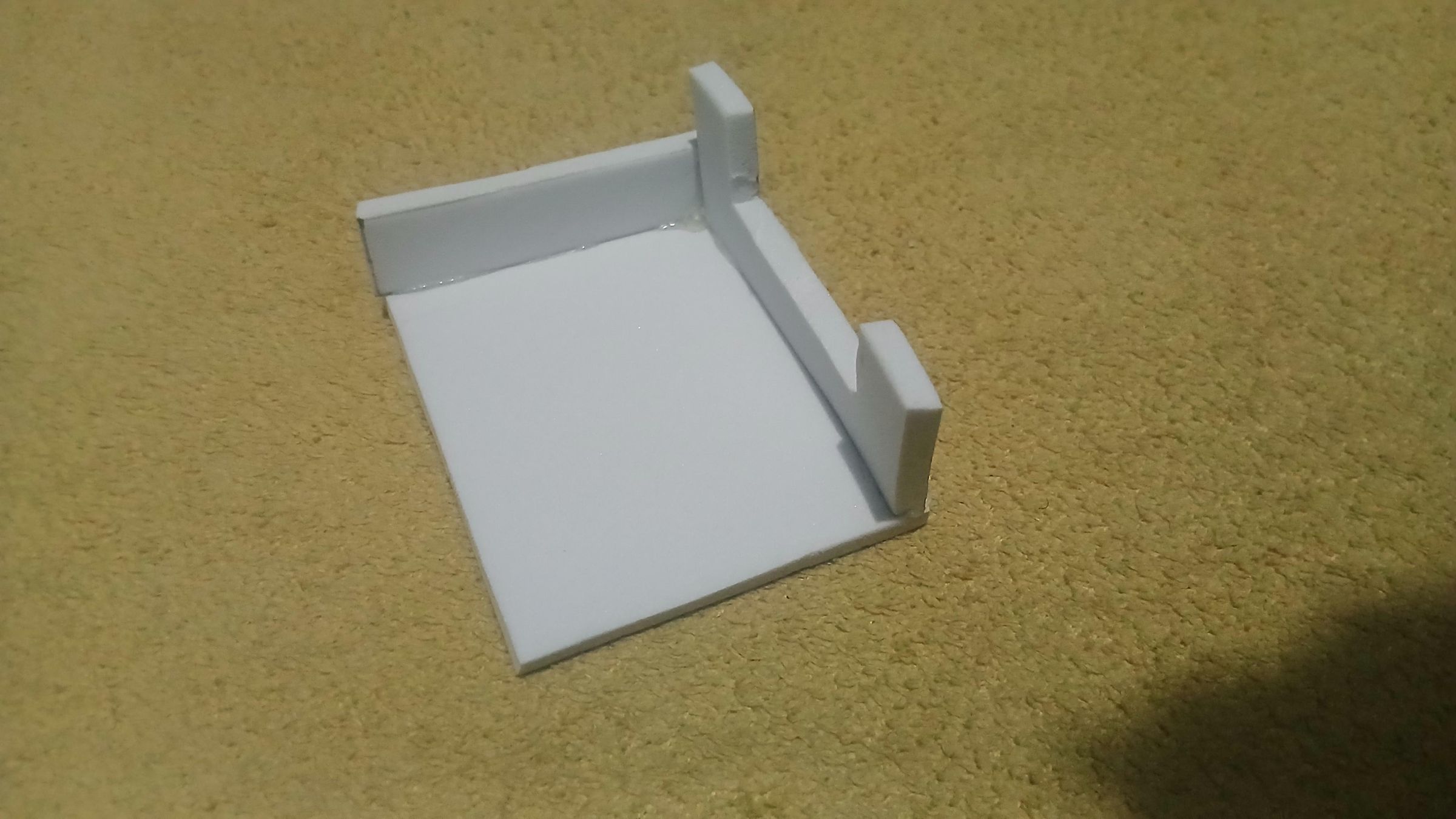
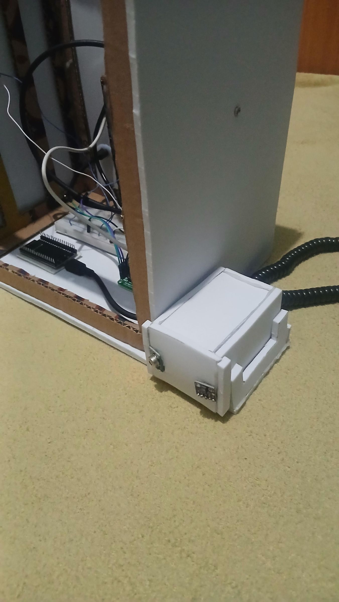
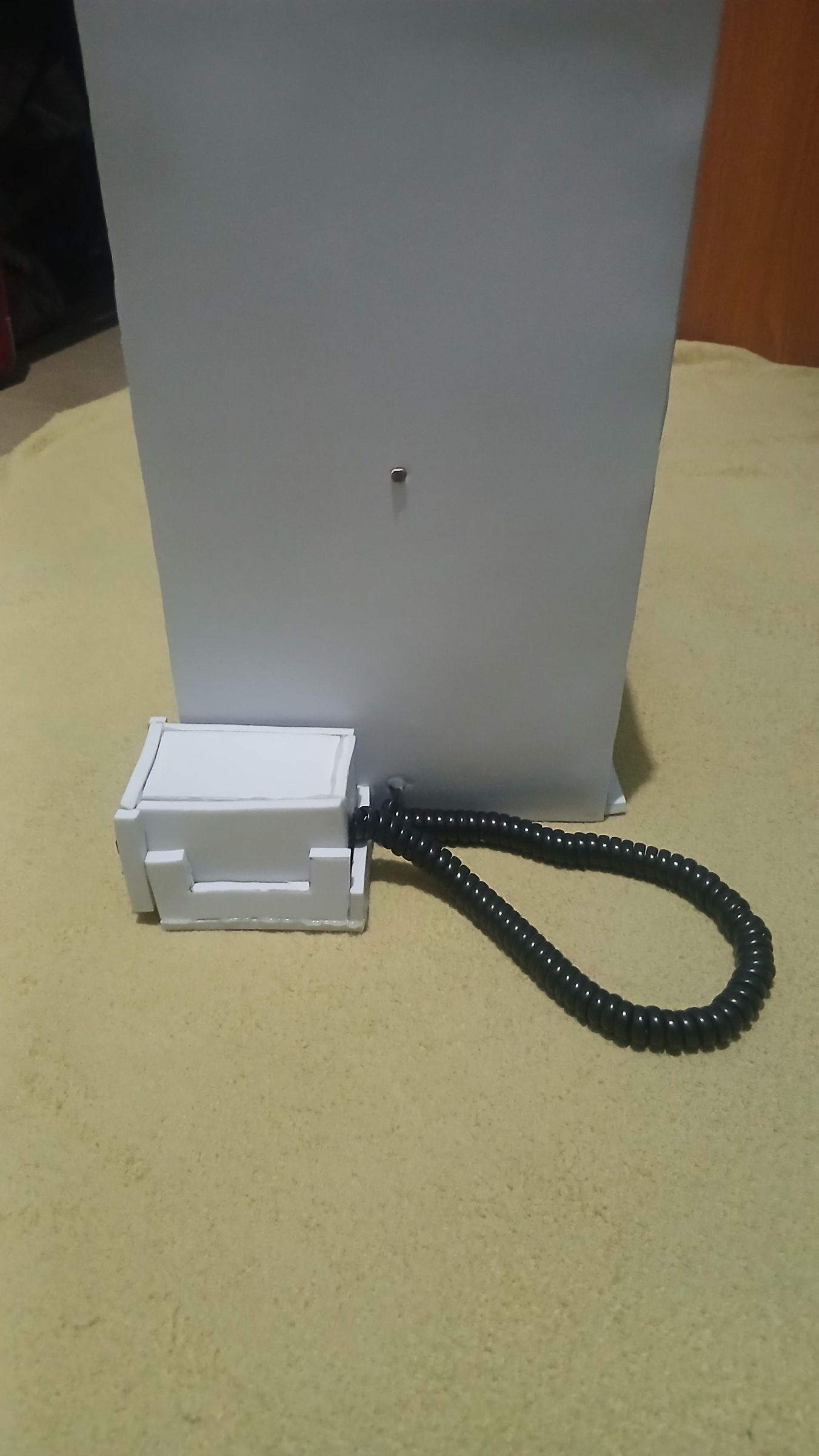
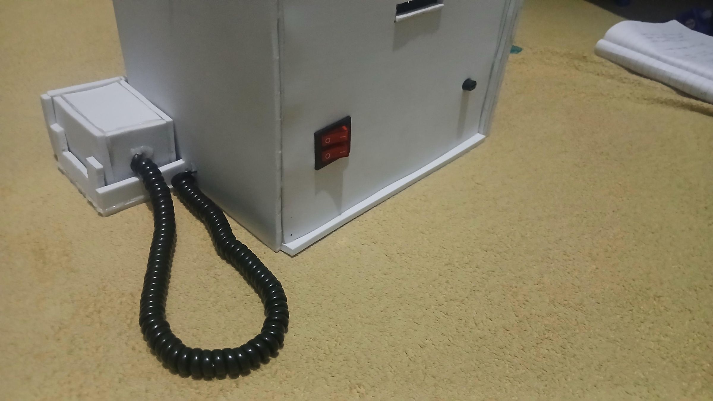
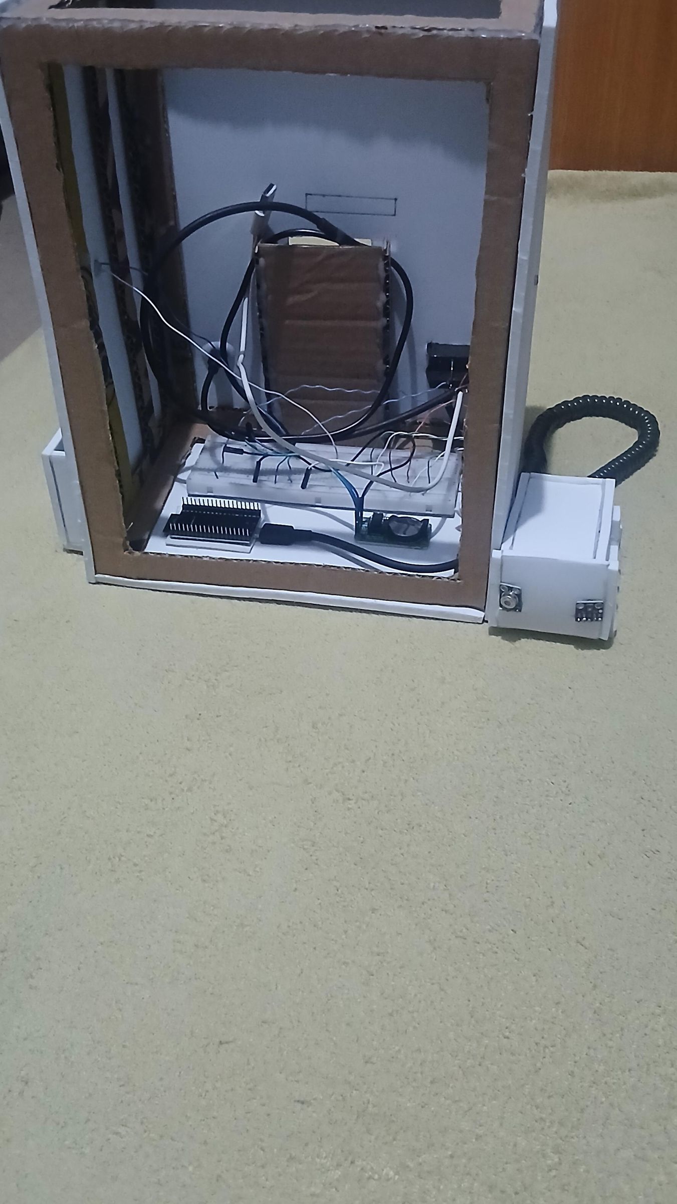
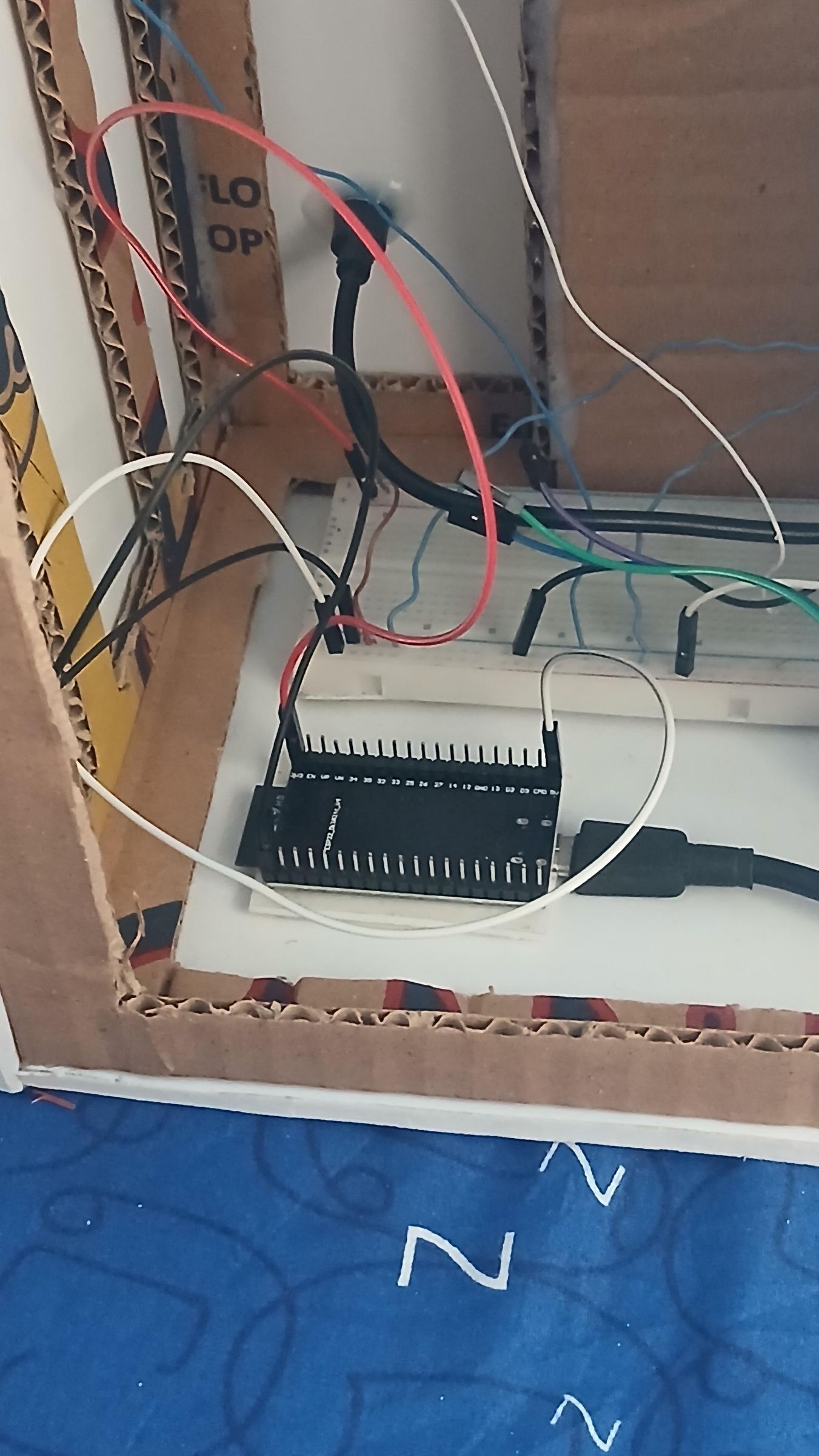
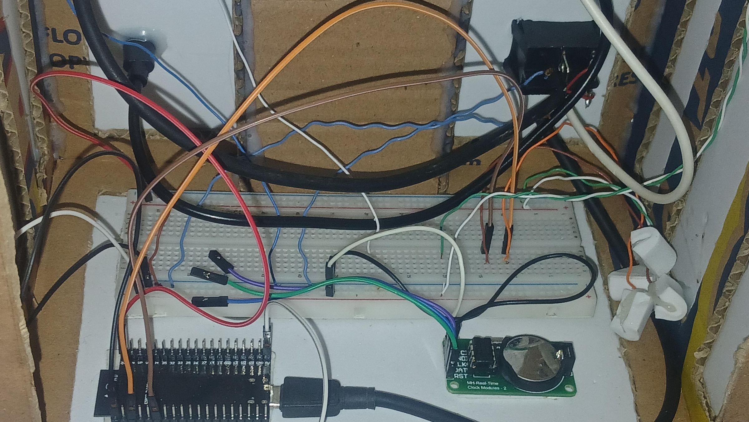
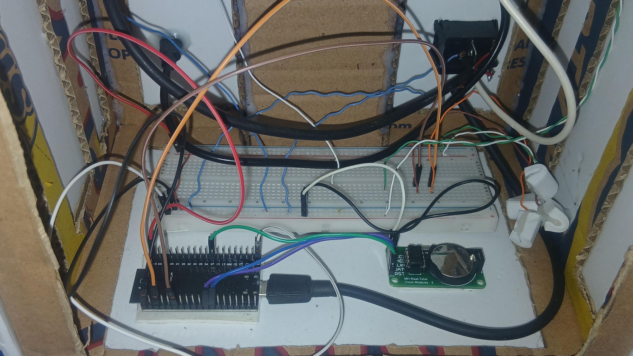
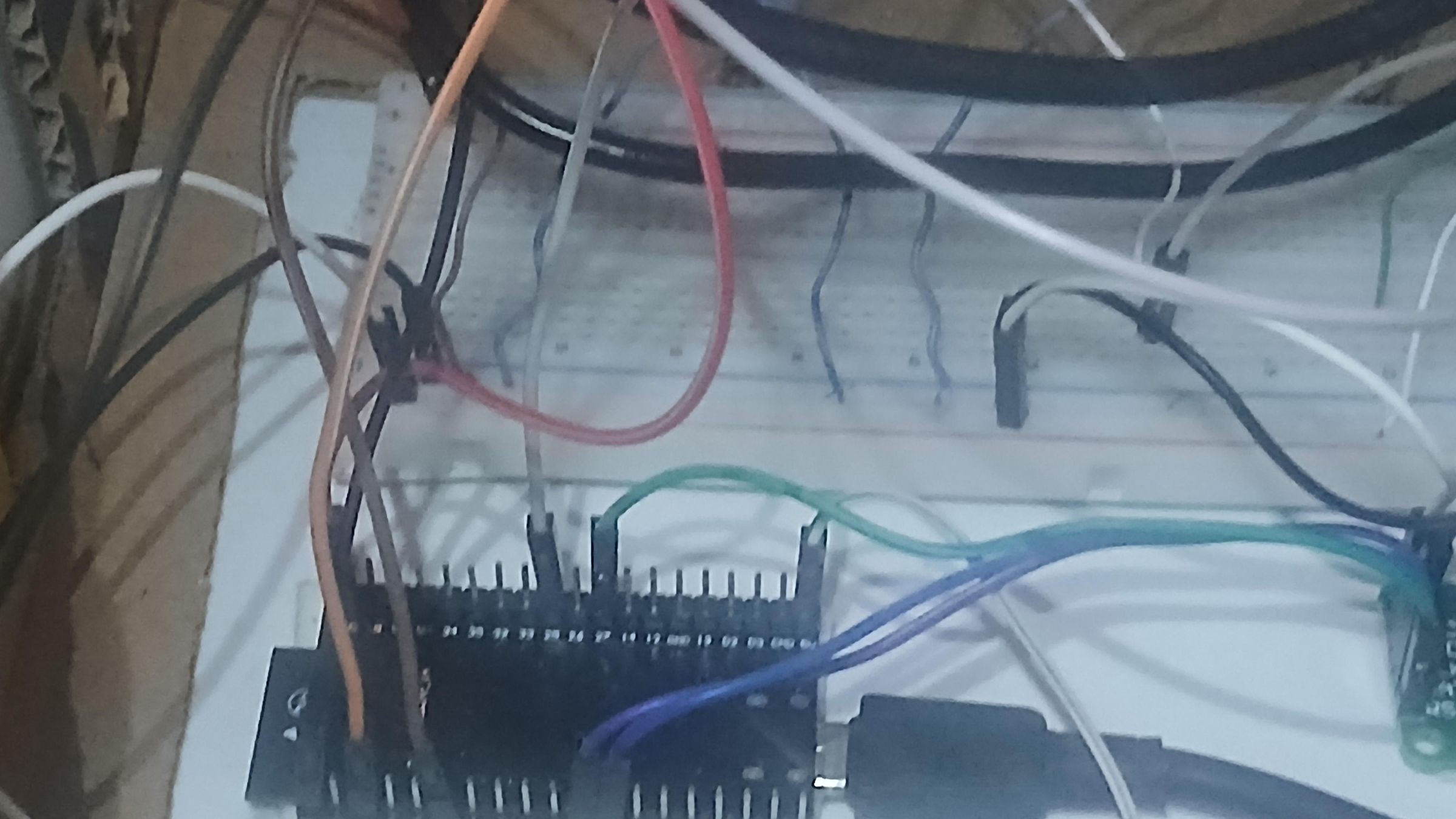
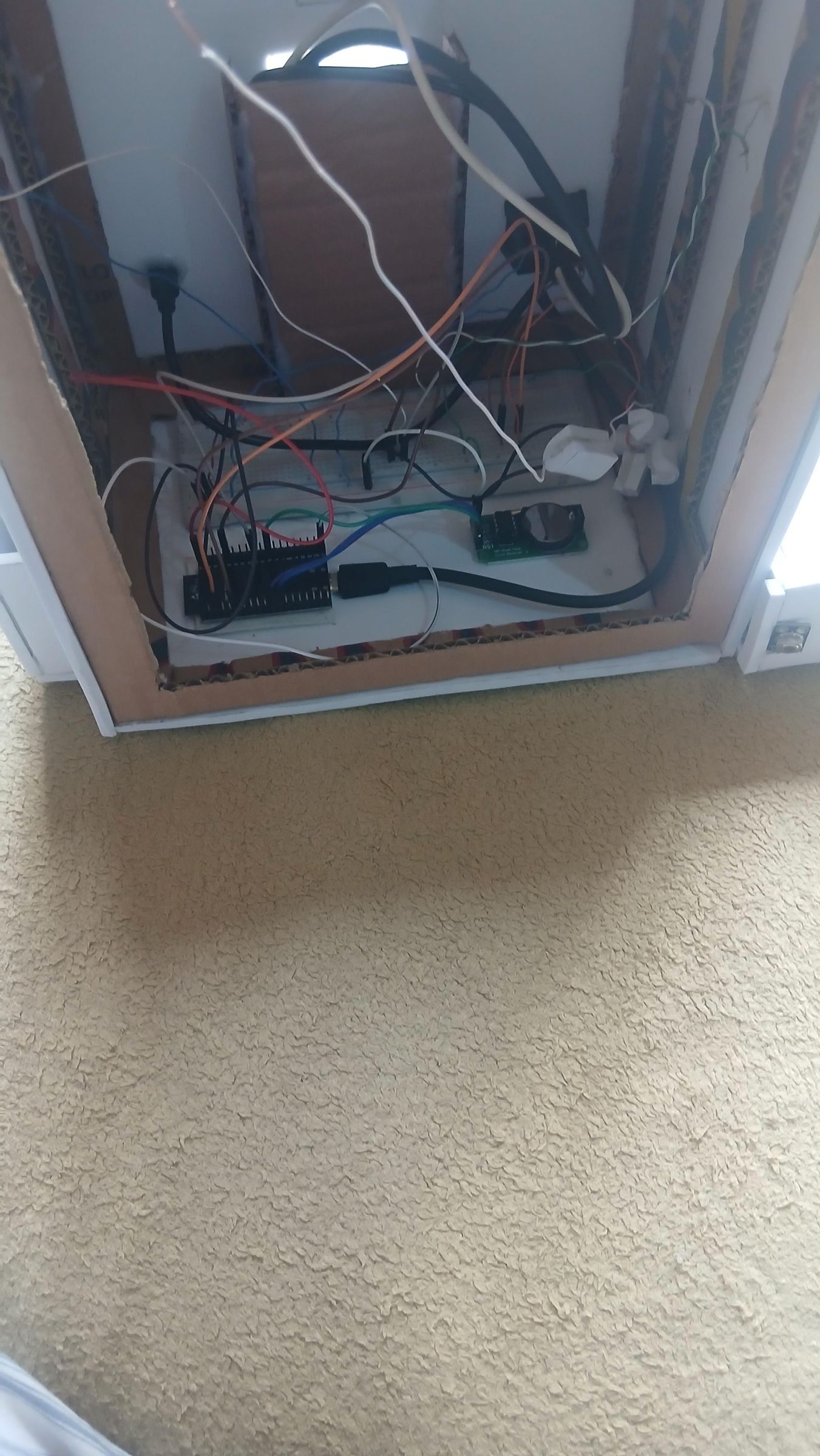
With the frame built and the core components (ESP32, breadboard, RTC) mounted from Step 2, this step covers wiring everything that lets Medi-Sense V2 actually sense and respond: the external vital-sign sensor pod, the passive buzzer, and the IR remote receiver — all tied back to the breadboard and into the ESP32's confirmed pins.
Full Pin-Out Reference
ESP32 GPIO assignments, pulled directly from the firmware:
I²C Bus (shared)
- SDA → GPIO21
- SCL → GPIO22
- Devices on this bus: LCD (16×4 I²C), MLX90614 (temperature), MAX30102/MAX30105 (heart rate & SpO₂)
Servo (pill dispenser)
- Signal → GPIO13
Buzzers
- Passive buzzer (signal) → GPIO25
- Active buzzer (signal) → GPIO18
LEDs
- Green LED 1 — Body Temp indicator → GPIO26
- Green LED 2 — Heart Rate indicator → GPIO33
- White LED — Dispensing indicator → GPIO14
Environmental sensor
- DHT11 (signal) → GPIO4
RTC (DS1302)
- CLK → GPIO17
- DAT → GPIO16
- RST → GPIO27
RGB status LED
- Red → GPIO23
- Green → GPIO5
- Blue → GPIO2
IR receiver (VS1838B)
- Signal → GPIO32
Removed in final build (no pins assigned in firmware)
- HC-SR04 ultrasonic sensor — not present
- LDR / photoresistor — not present
Power rails for this step
Both the 3.3V and 5V rails on the breadboard are jumped directly from the ESP32's own power pins — the ESP32's 3.3V pin feeds one side of the breadboard, and its 5V pin feeds the other side. This gives two clean, separated rails to pull from depending on what each component needs, without running new wires back to the power source every time.
The MLX90614 and MAX30102 both talk over the same I²C bus (SDA/SCL), so they share those two signal lines on the breadboard rather than needing separate signal pins each. Both sensors are 3.3V-logic parts, so their VIN pins are wired to the 3.3V side of the breadboard — not the 5V side — since 5V on these sensors' VIN or signal pins can damage them.
What's happening in this step
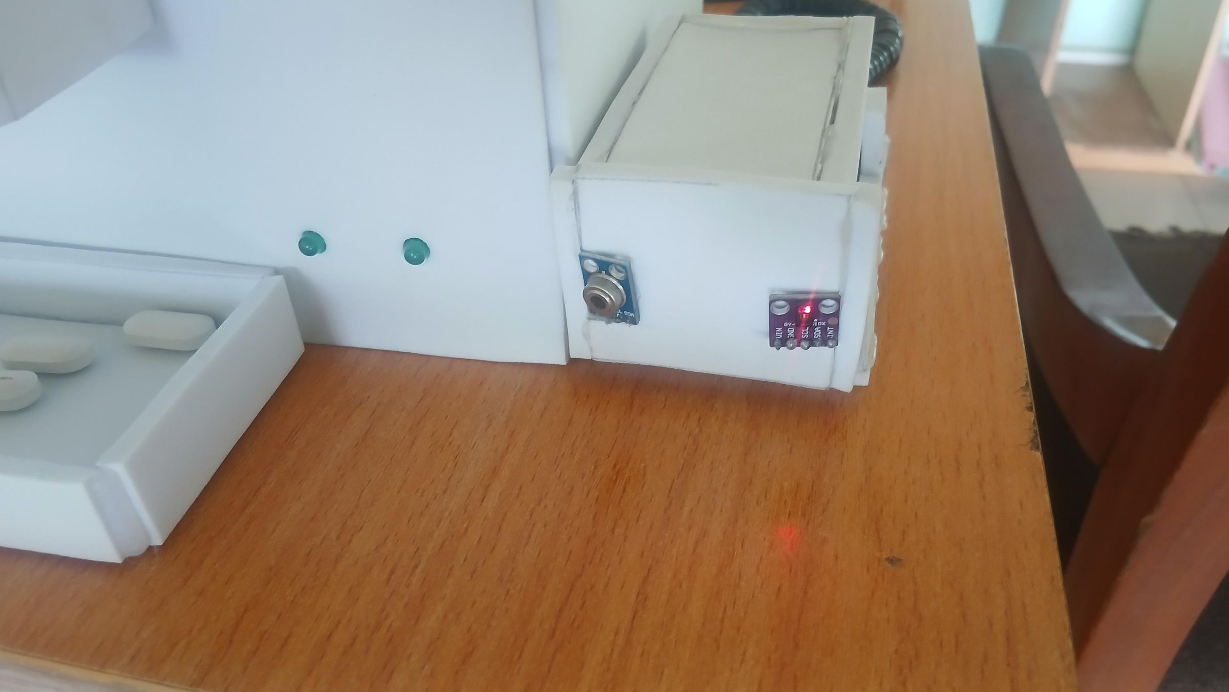
- Build the vital-sign sensor pod. Rather than mounting the MLX90614 and MAX30102 inside the main enclosure, they're wired up and seated into their own small foam-board housing — a compact box just big enough to hold both sensors flush against its front face, pointing outward. This keeps the sensors physically separate and easy to aim (finger on the MAX30102, hand near the MLX90614) without opening the main case.
- Wire both sensors onto the shared I²C bus. Jumper wires from each sensor's VIN, GND, SCL, and SDA pins run to the breadboard's 3.3V rail and ground, and to GPIO21 (SDA) / GPIO22 (SCL), joining the same bus the RTC and LCD also sit on.
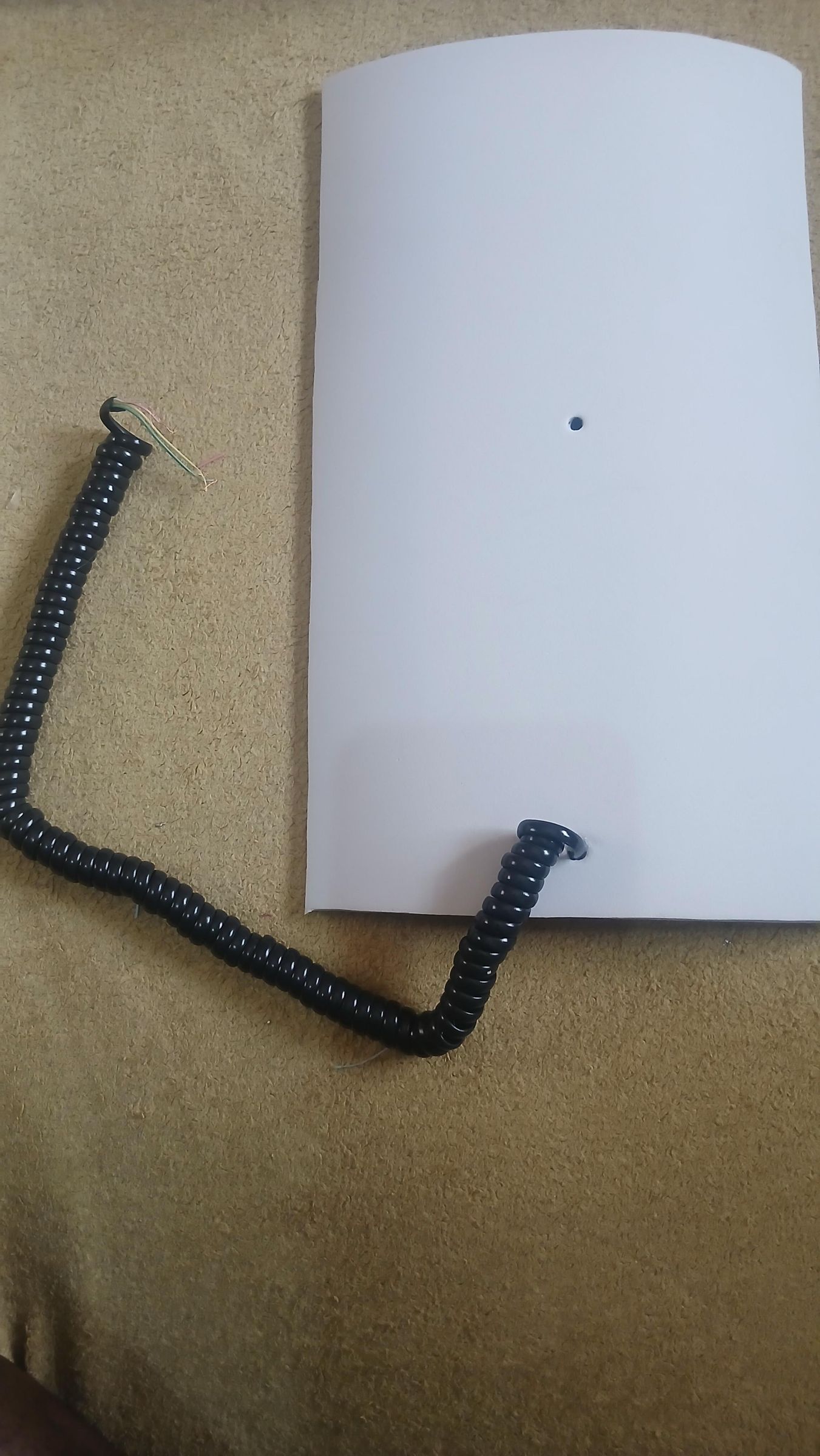
- Route power and signal through the curly cable. Since the sensor pod sits outside the main enclosure, its wires bundle together and run through a stripped, curly phone-style cord back into the main body — keeping the external pod tidy and removable rather than having loose wires running between the two housings.
- Mount the pod to the side of the main enclosure. A small foam-board bracket holds the sensor housing flush against the main body's side panel, with the curly cable looping between them.
- Wire the passive buzzer. The buzzer's two leads run to GPIO25 (signal) and ground on the breadboard. In firmware this drives buzzerTone(), a manual square-wave generator that produces the confirmation beeps (beepOK), error tones (beepErr), and key-press ticks (beepTick) — no separate tone library needed.
- Wire the IR receiver. The VS1838B's output goes to GPIO32, which IrReceiver.begin() reads to decode button presses from the remote (digits 0–9 map to dispenser commands and time-setting, per the firmware's irDigit() function).
- Dress the wiring. All the new jumper wires — red, orange, brown, white, green, purple, blue — get routed along the inside back wall, past the RTC module, and down into the breadboard alongside the existing power and signal cables from Step 2
The code and Serial bluetooth terminal app is provided below:
Downloads
Building the Top and Front Panel
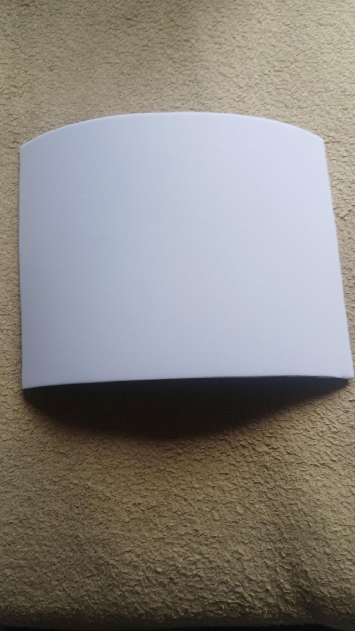

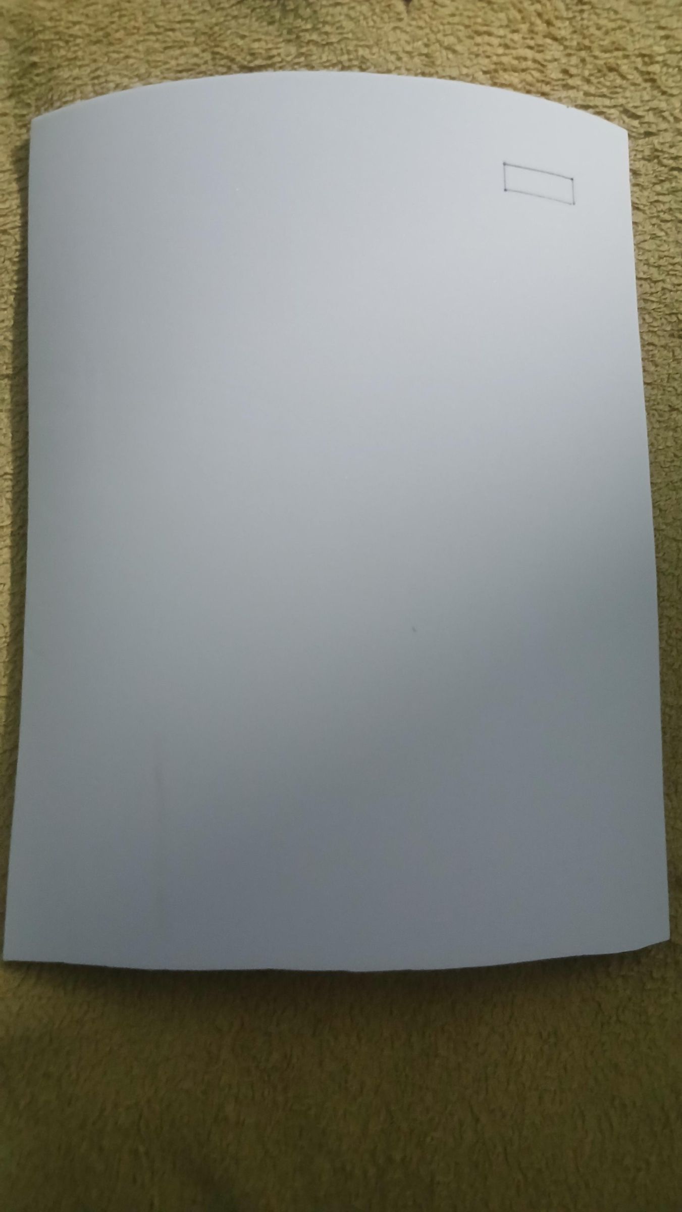
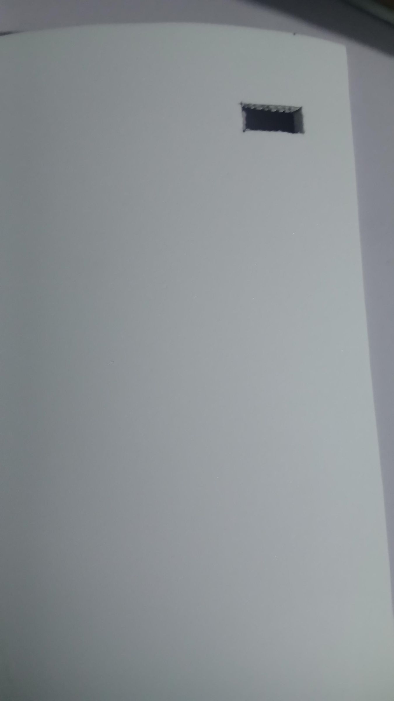
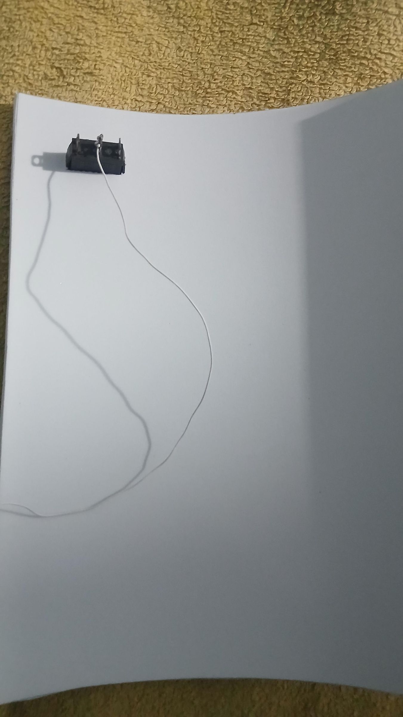
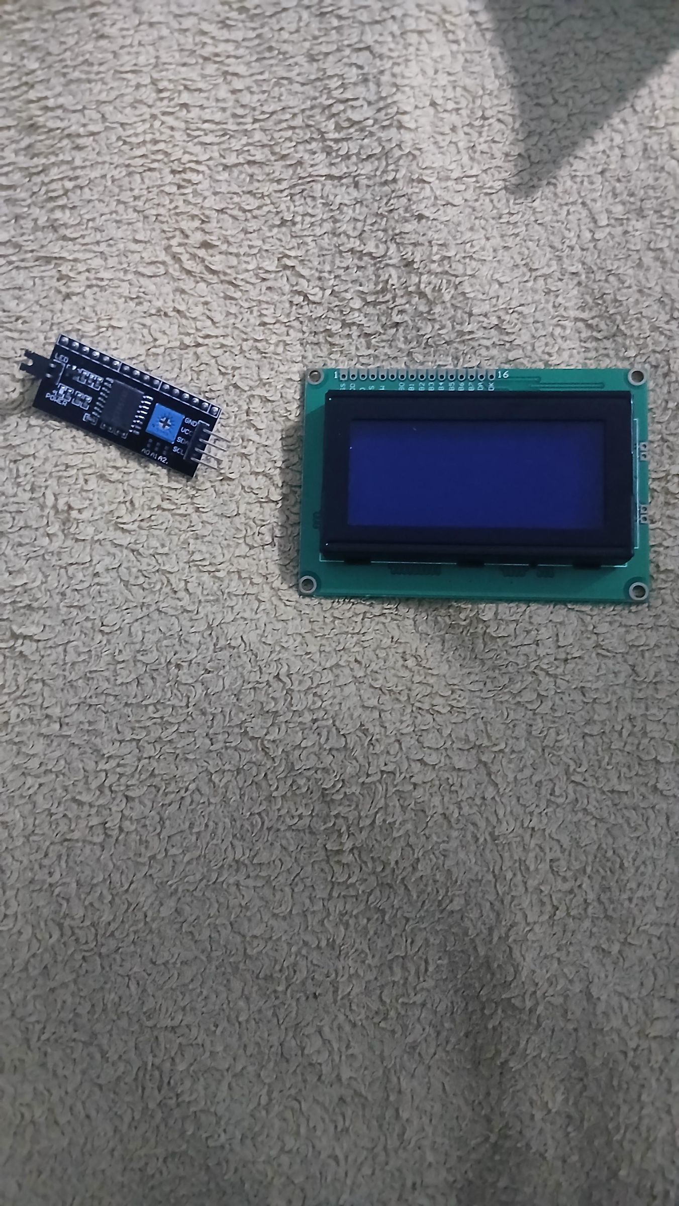
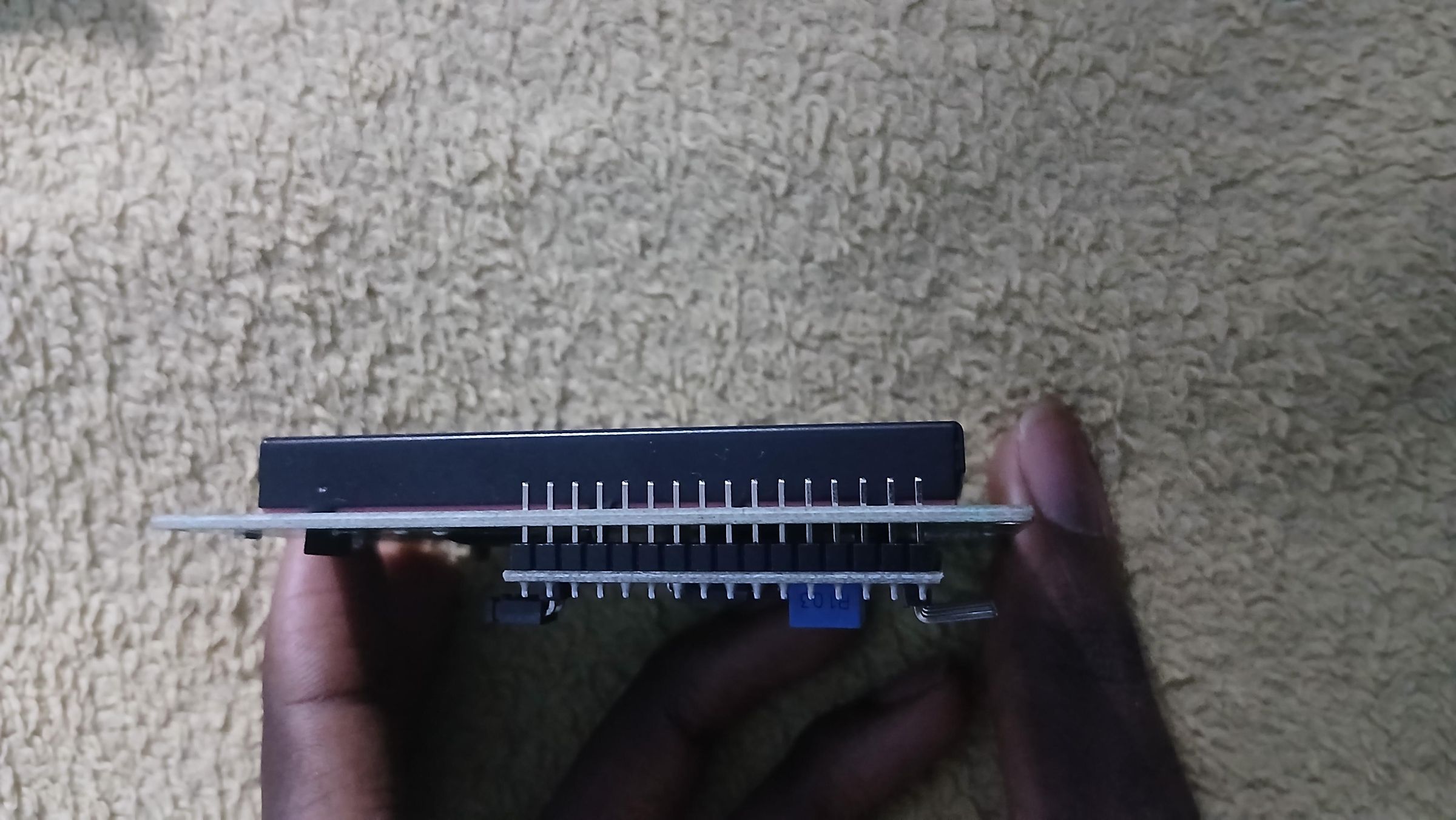
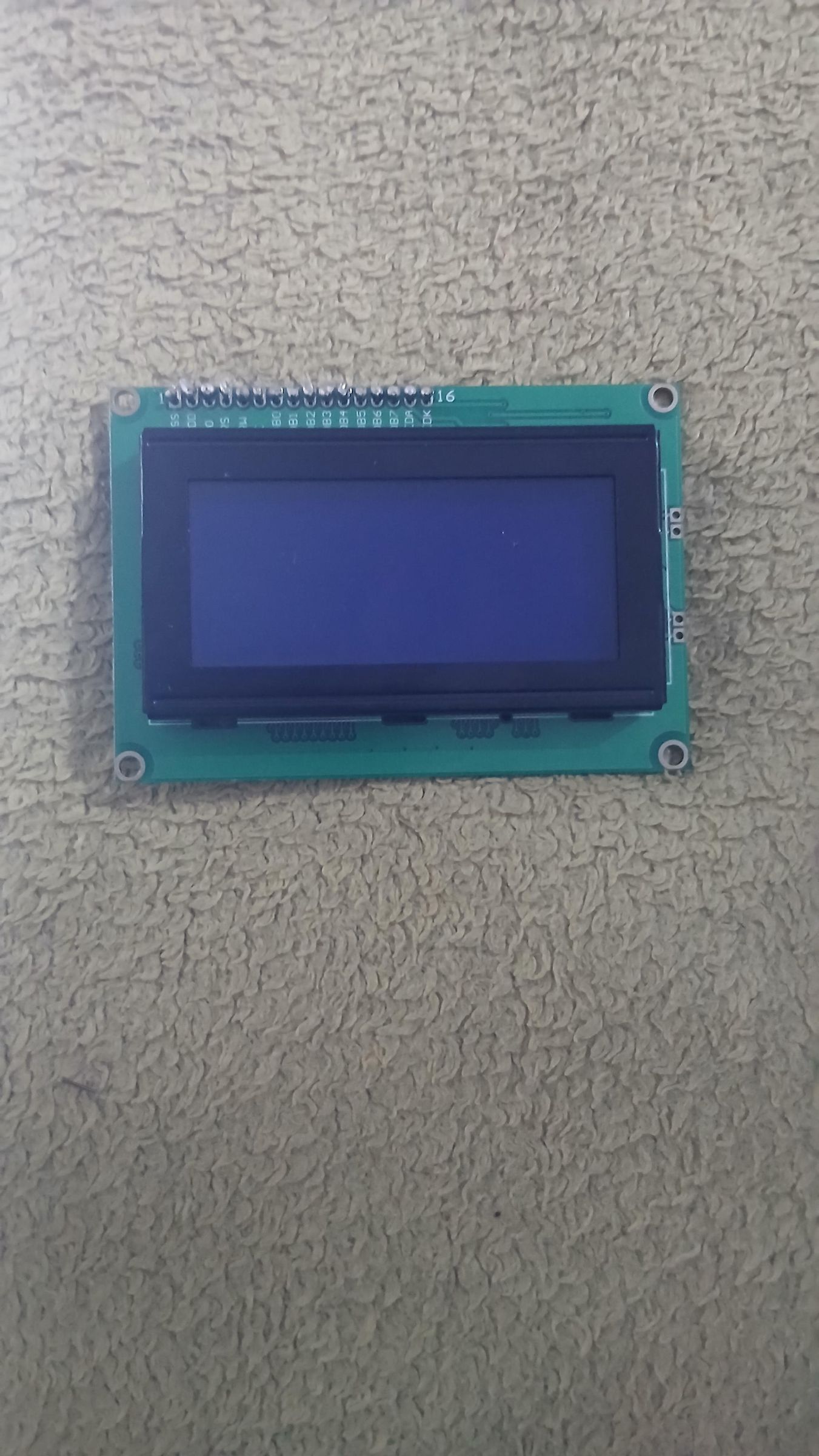
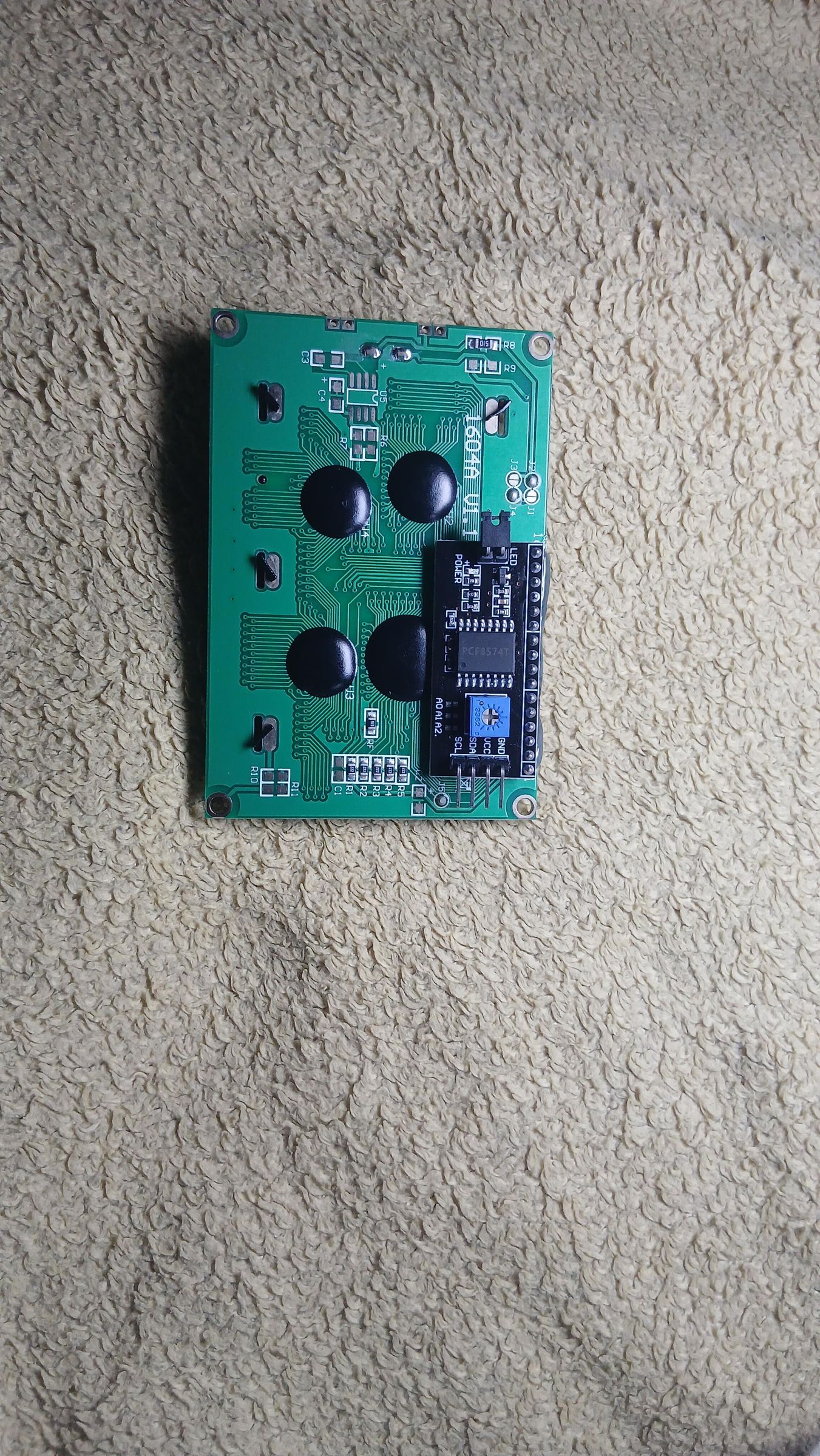
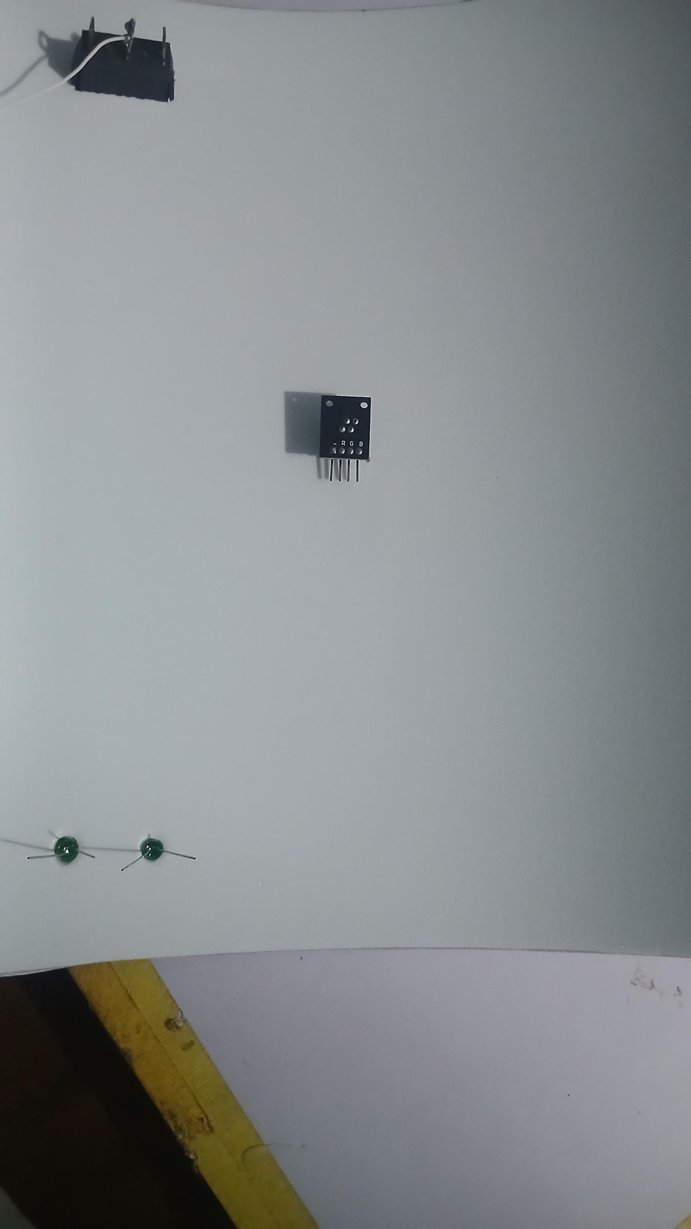
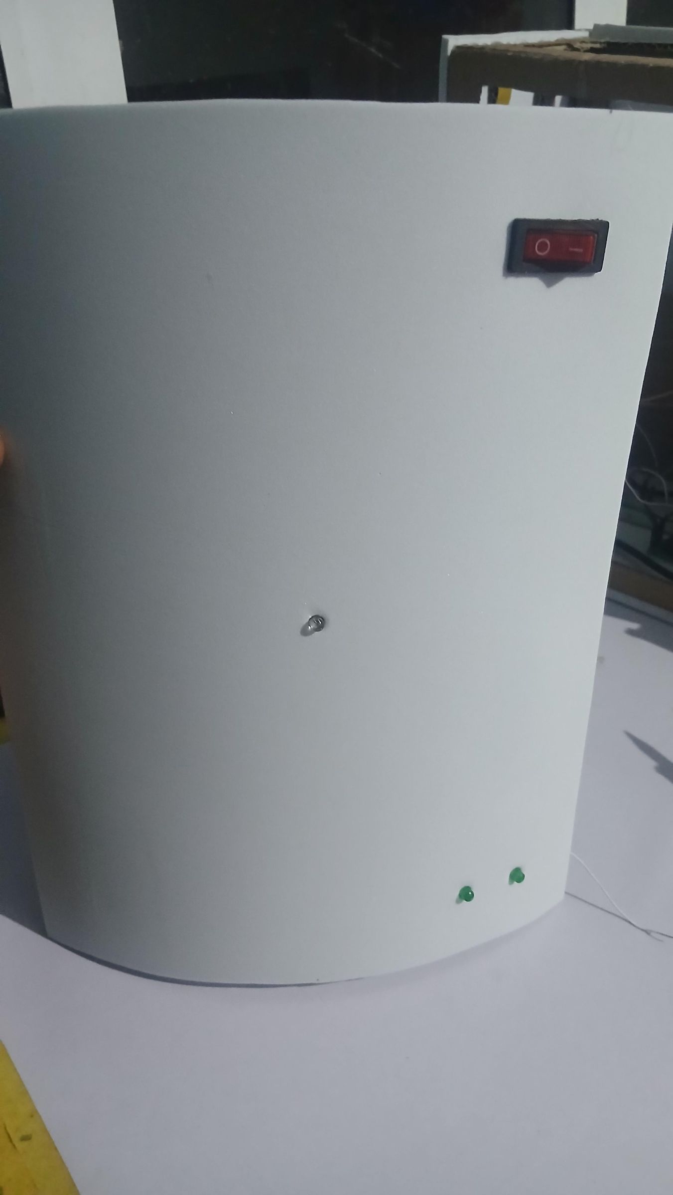
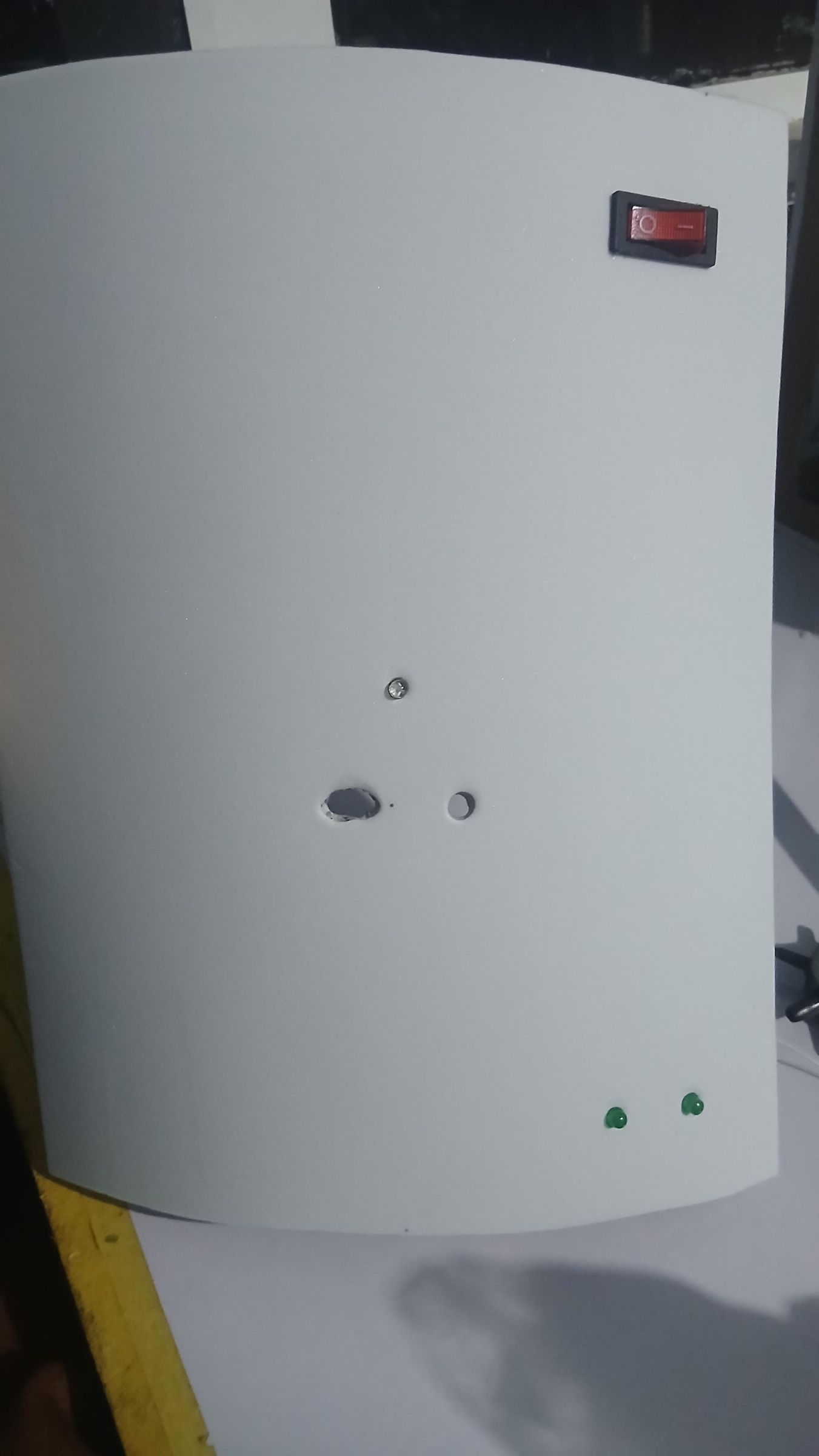
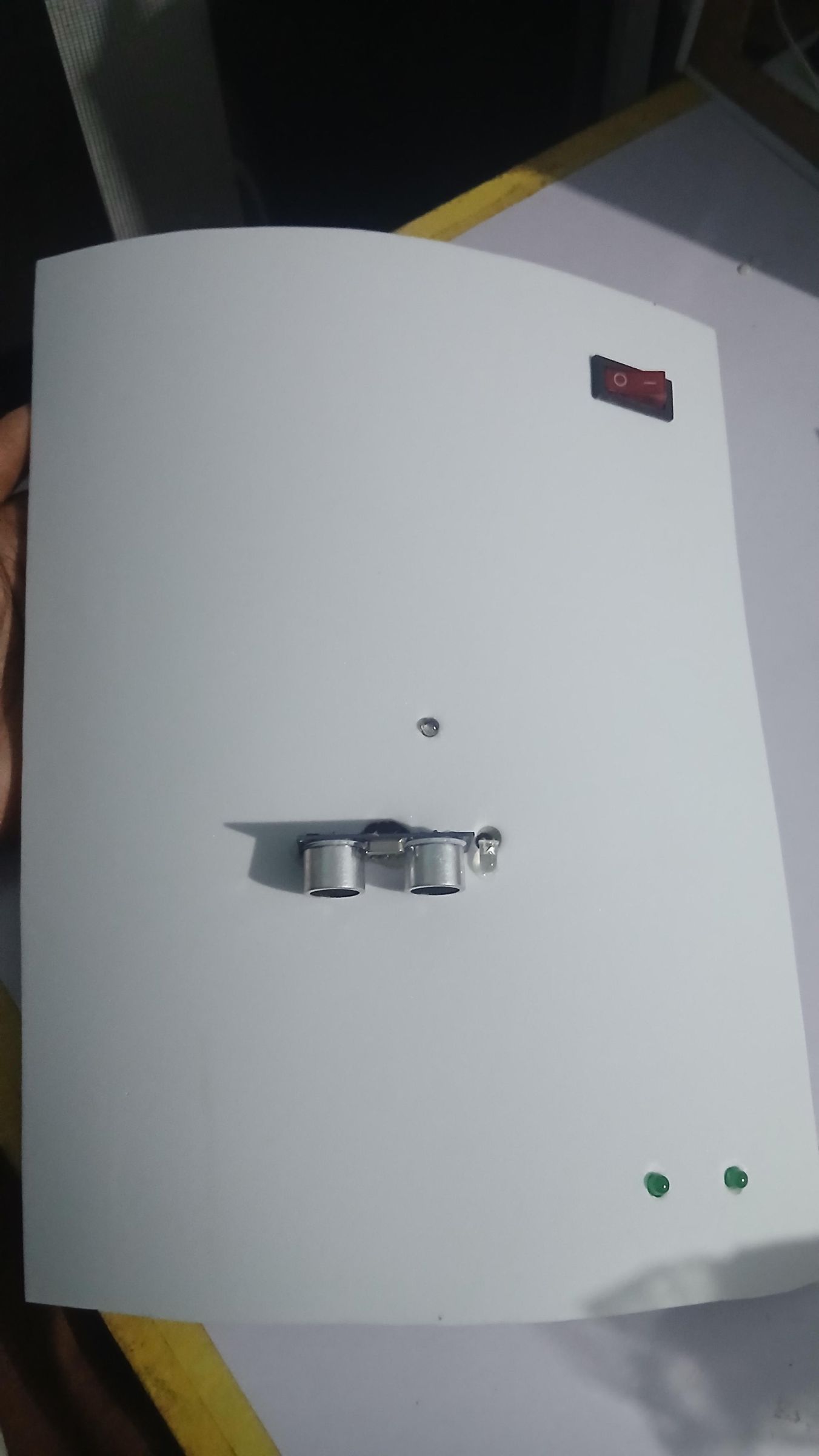
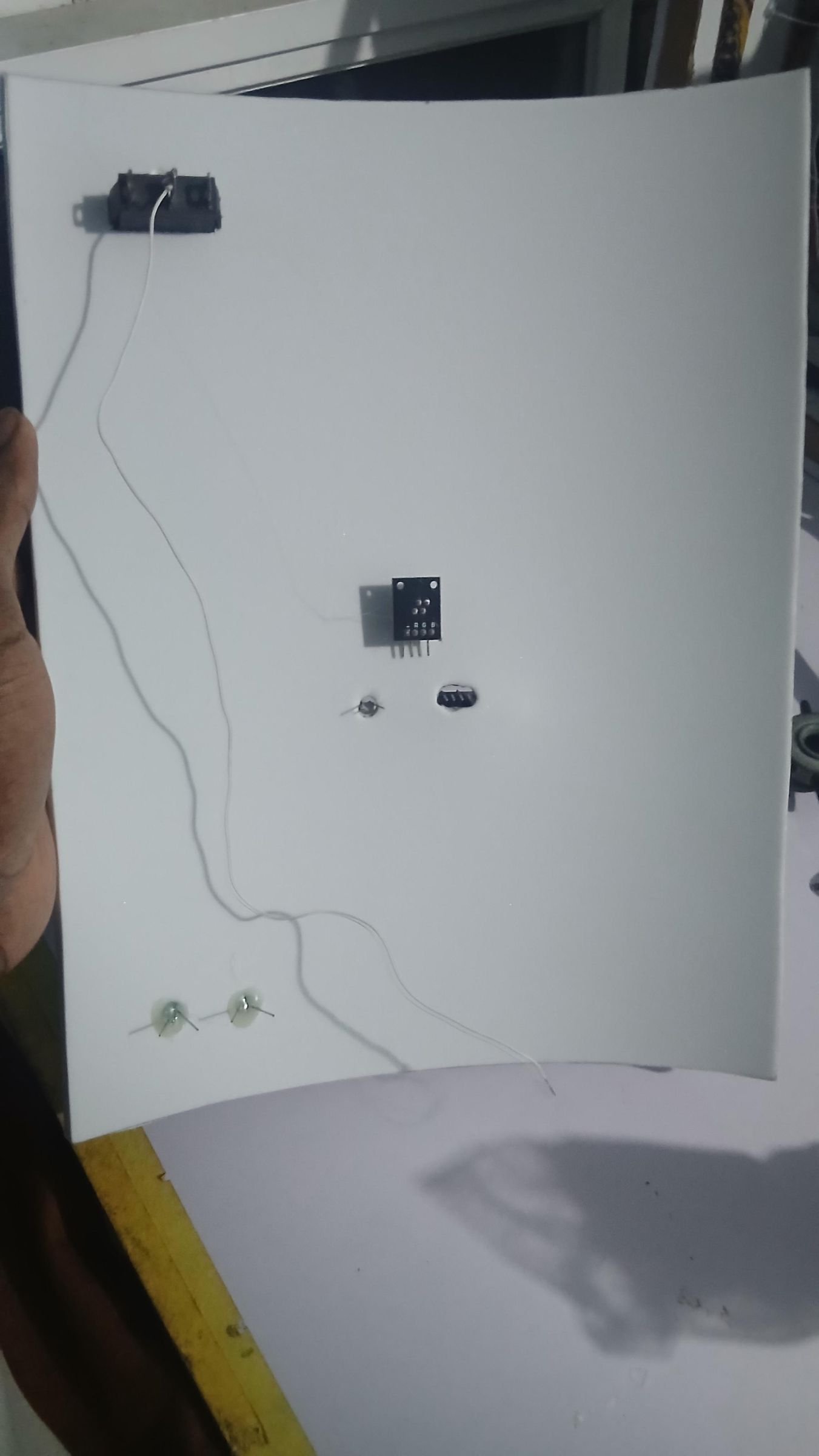
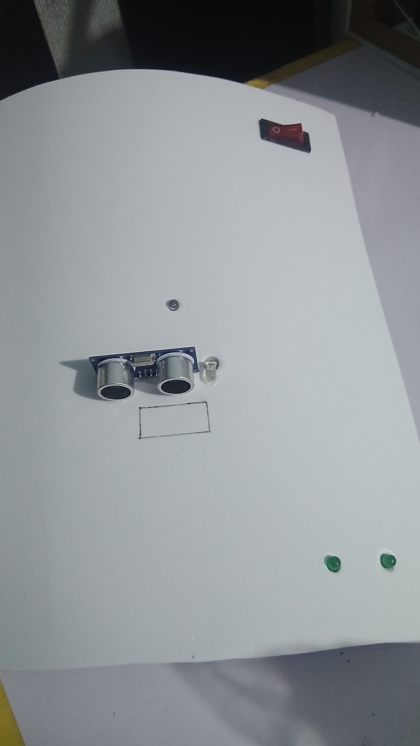
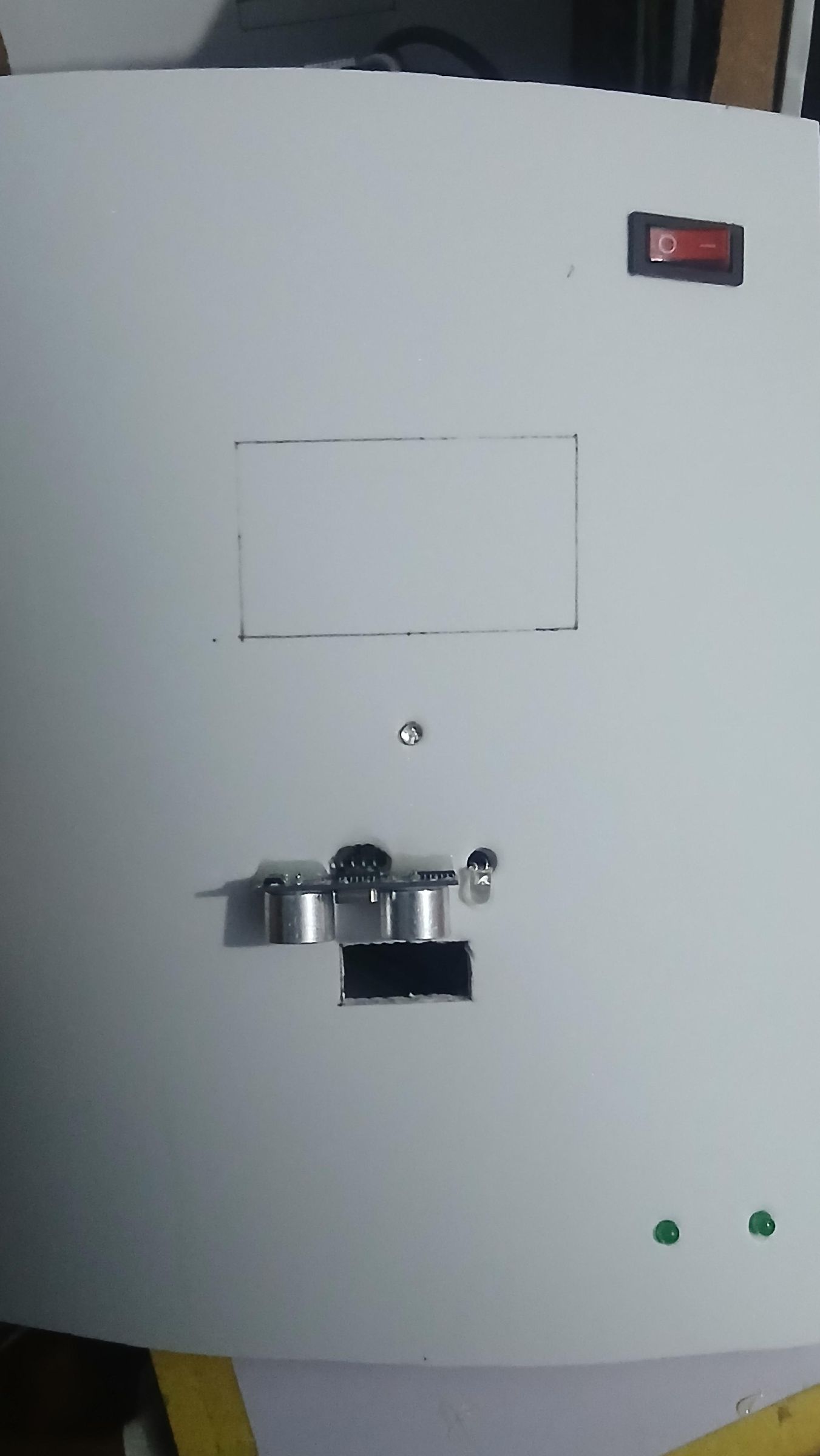
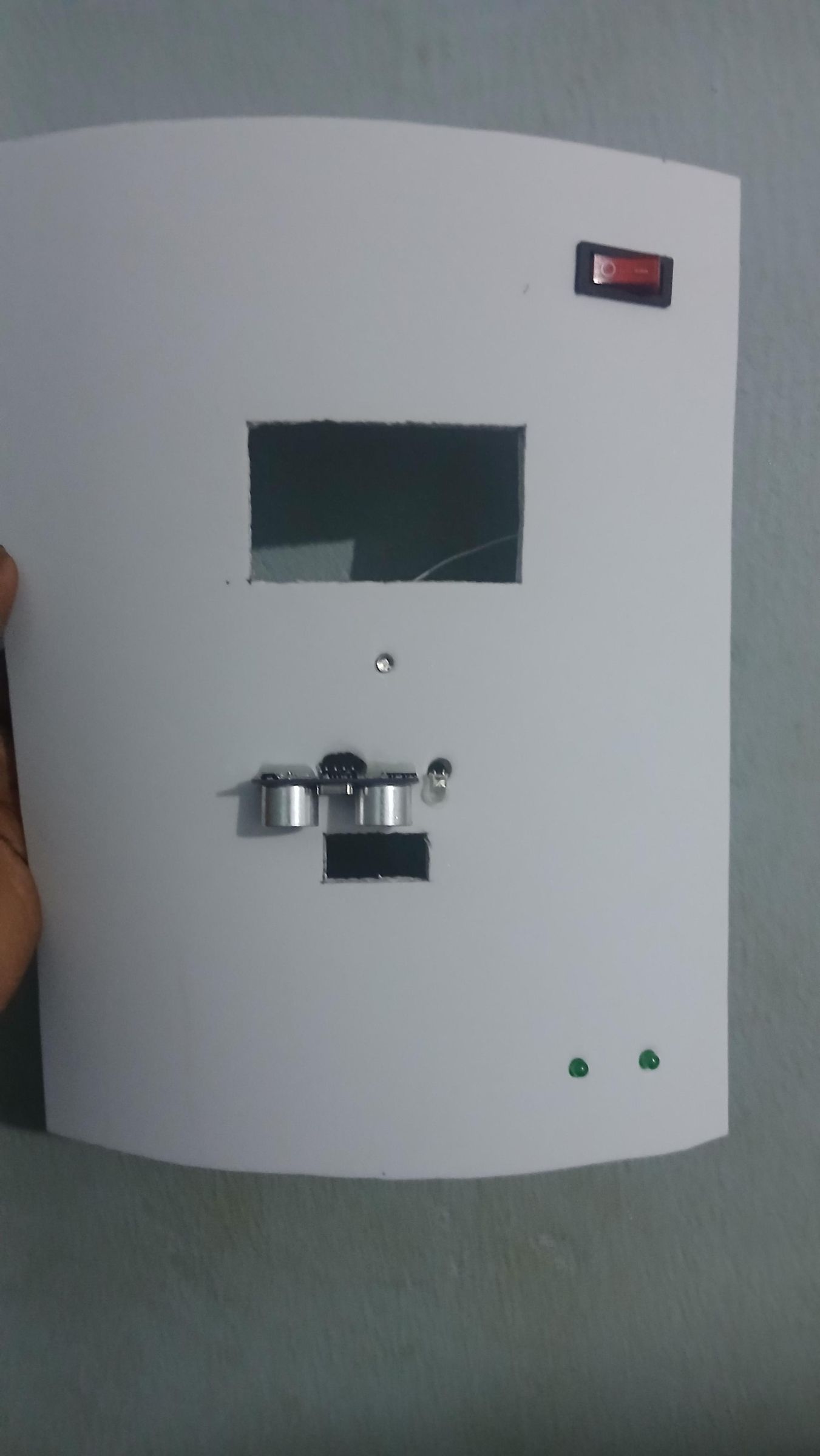
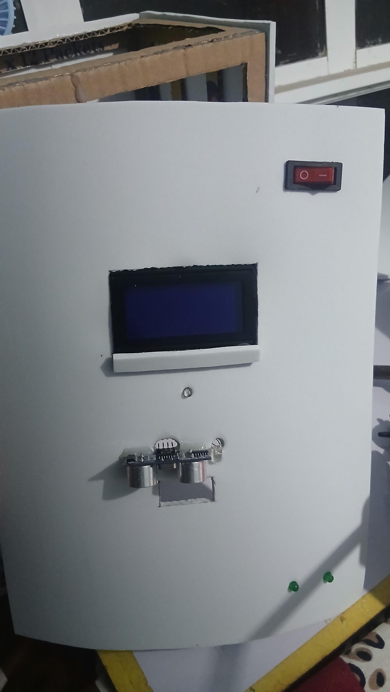
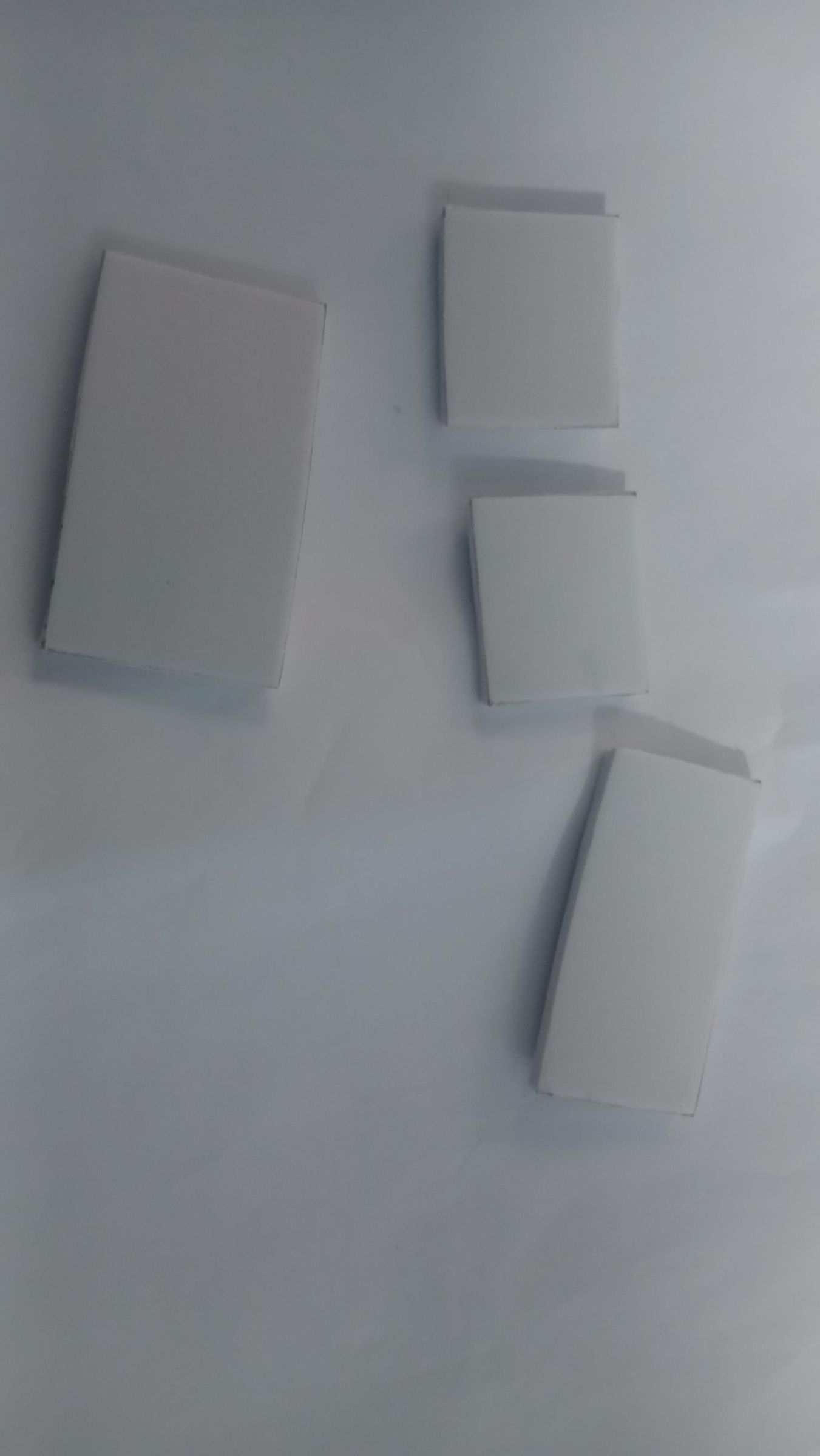
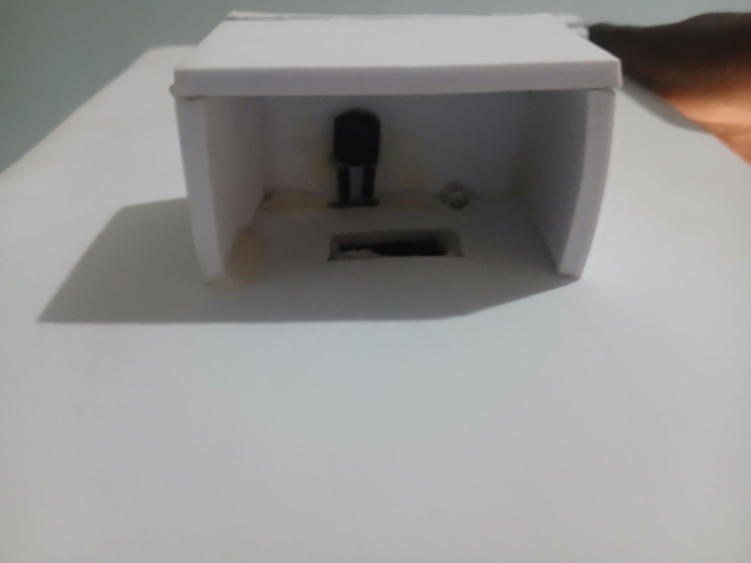
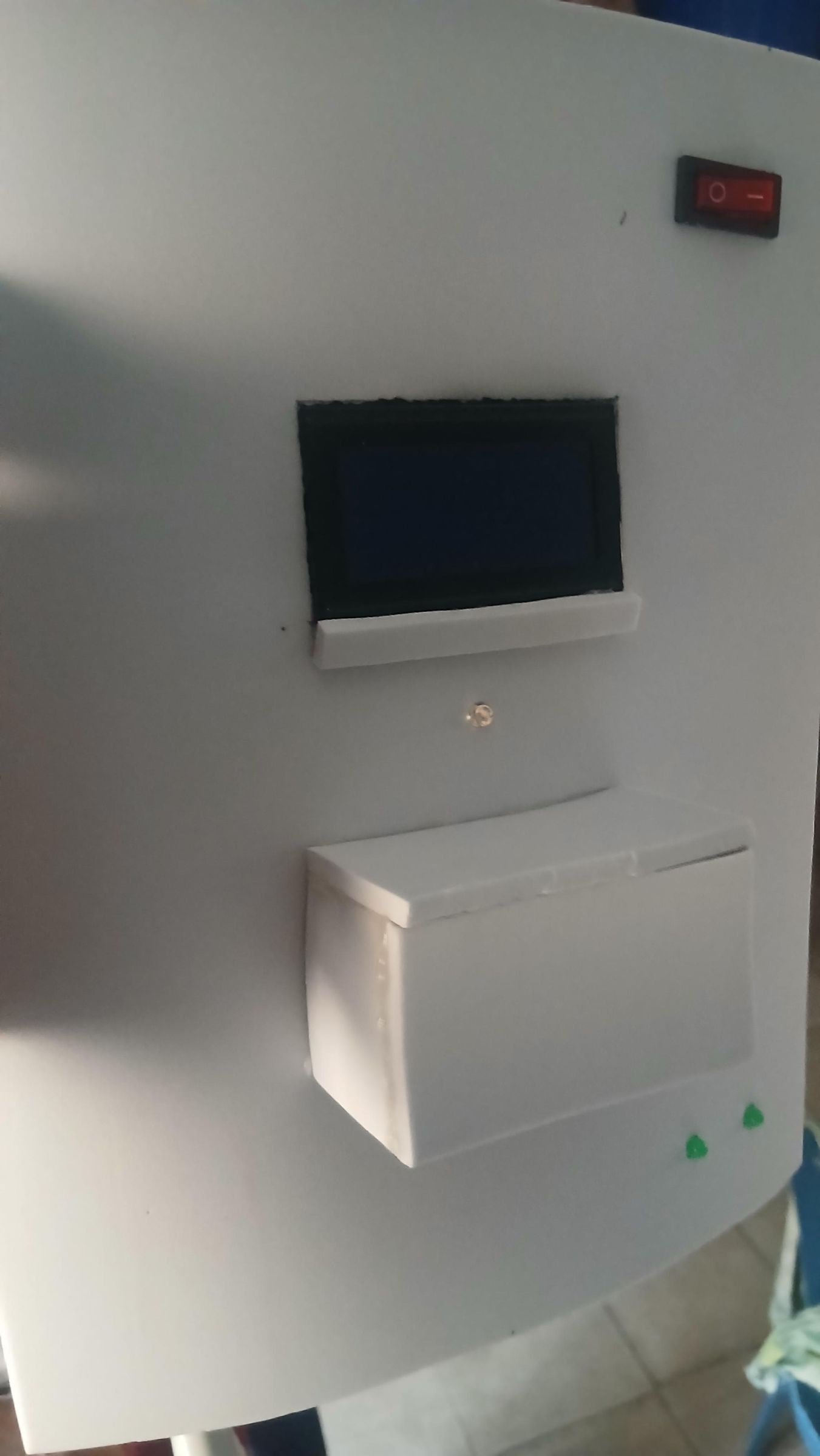
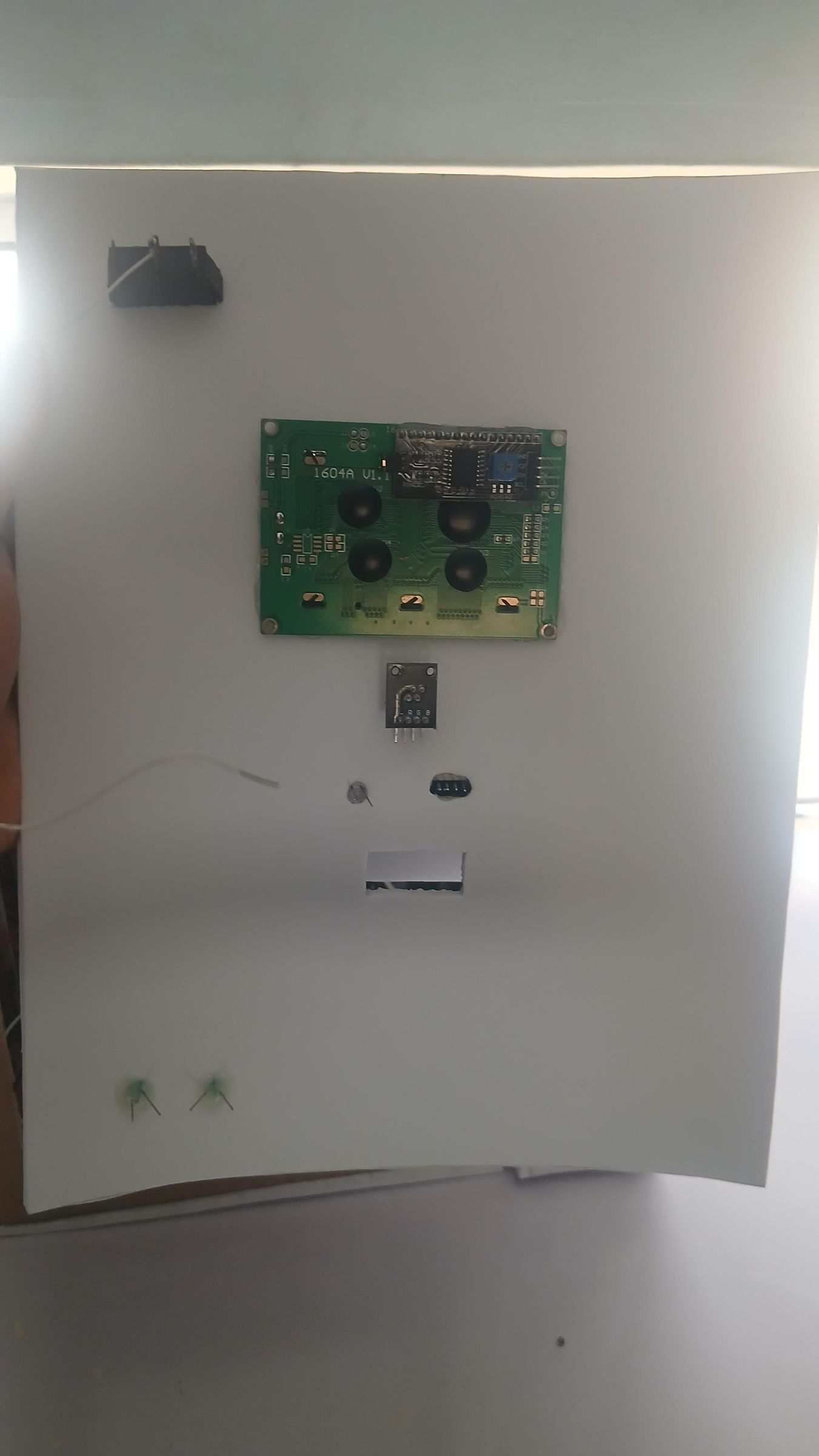
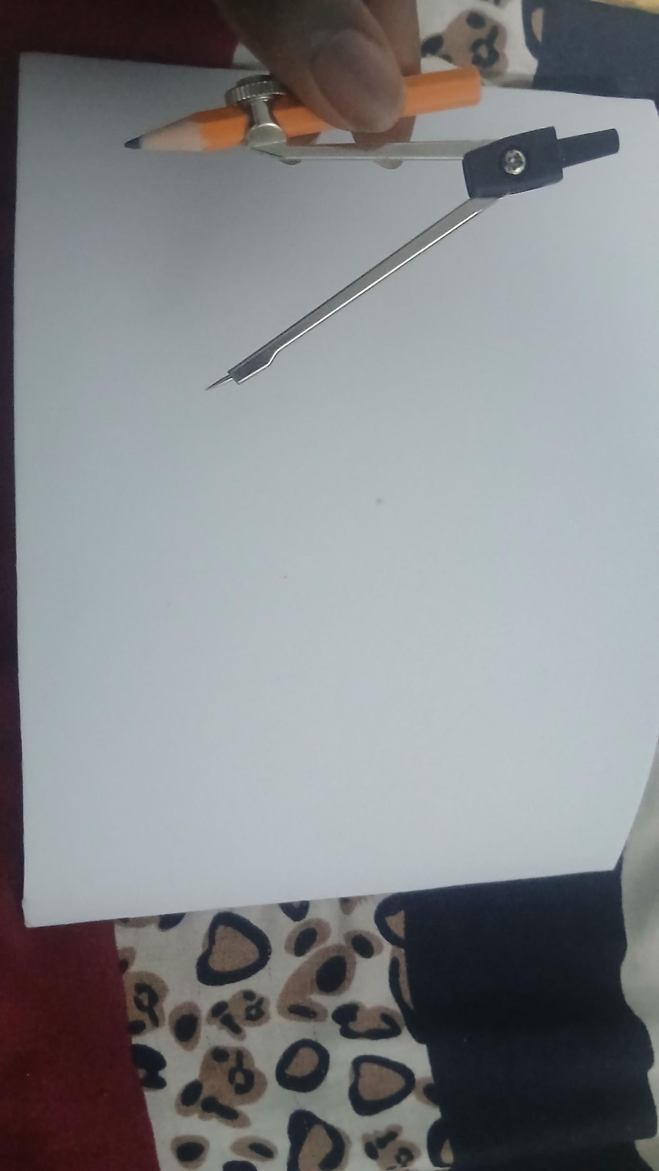
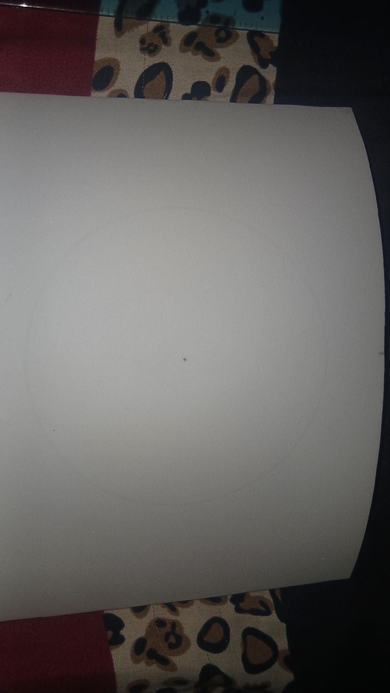
With the enclosure shell ready, this step covers shaping the top panel and the front panel, then mounting the components that live on each.
Cutting the top and front panel
Start by cutting the major curved top piece to size, followed by the front panel. Both pieces use the same curved profile to match the enclosure body. Dry-fit each piece against the shell before cutting any holes — it's much easier to mark accurately against the actual case than to measure in isolation.
Marking the pill-disk rotation cutout
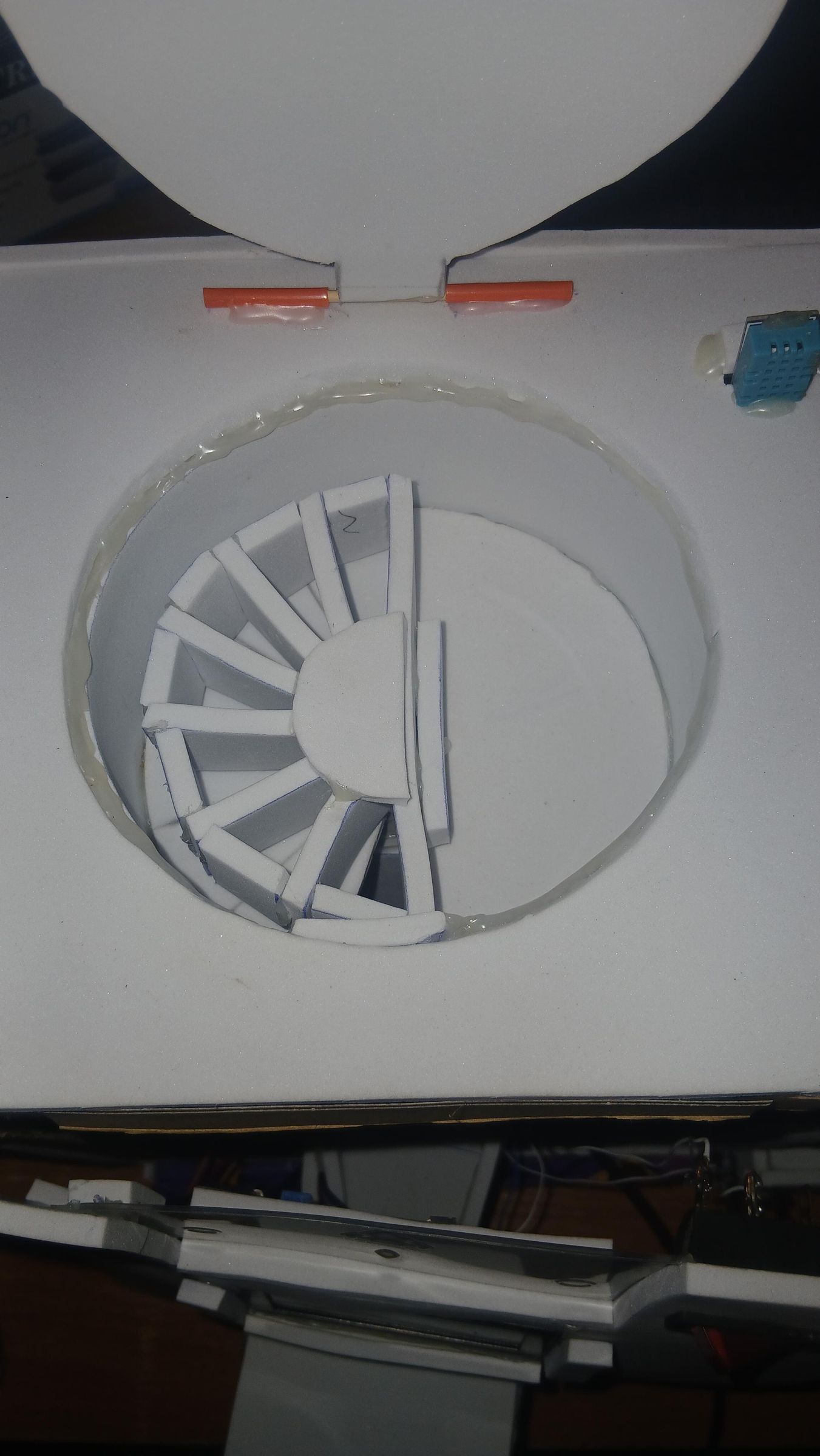
On the top panel, use a compass to mark out the circular cutout with a 6.25cm radius that will later house the pill disk rotation mechanism, driven by the SG90 servo on GPIO 13. Set the compass to the radius of your disk, anchor the point at your planned center, and trace the full circle in pencil before cutting. Don't cut this hole yet if your servo mount isn't finalized — mark it first, confirm alignment with the servo and disk assembly, then cut.
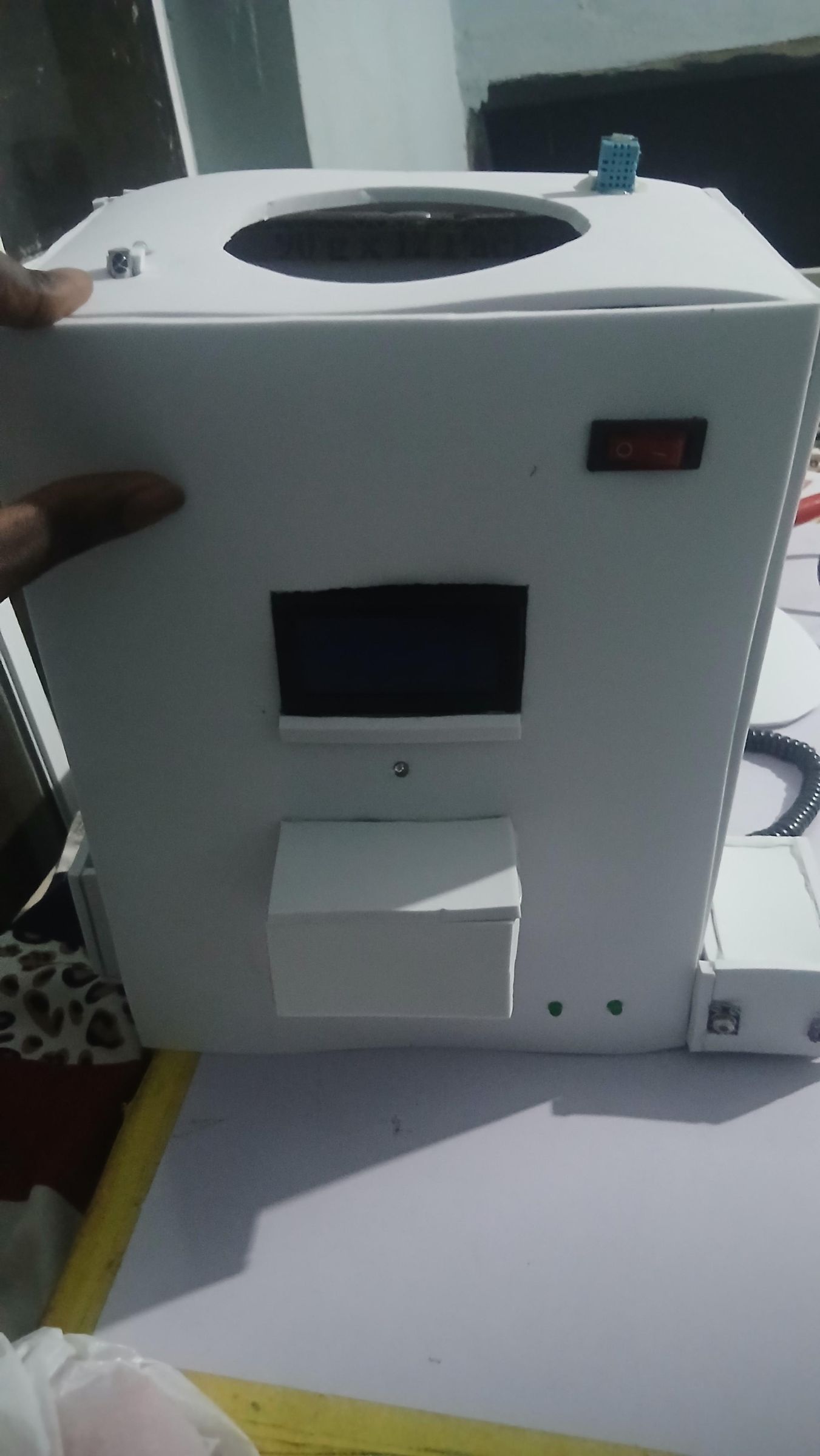
Front panel layout and drilling
On the front panel, mark and drill mounting points for the following, with their corresponding ESP32 pins so wiring is straightforward once the panel is cut:
- Vital sign rocker switch — disabled/not included
- RGB status LED — Red on GPIO 23, Green on GPIO 5, Blue on GPIO 2
- Green LED 1 (Body Temp indicator) — GPIO 26
- Green LED 2 (Heart Rate indicator) — GPIO 33
- White LED (dispensing indicator) — GPIO 14, lights only while the servo is actively dispensing
- Active buzzer — GPIO 18 (a second, passive buzzer is on GPIO 25, it was mounted exactly where the ultrasonic sensor would have been placed)
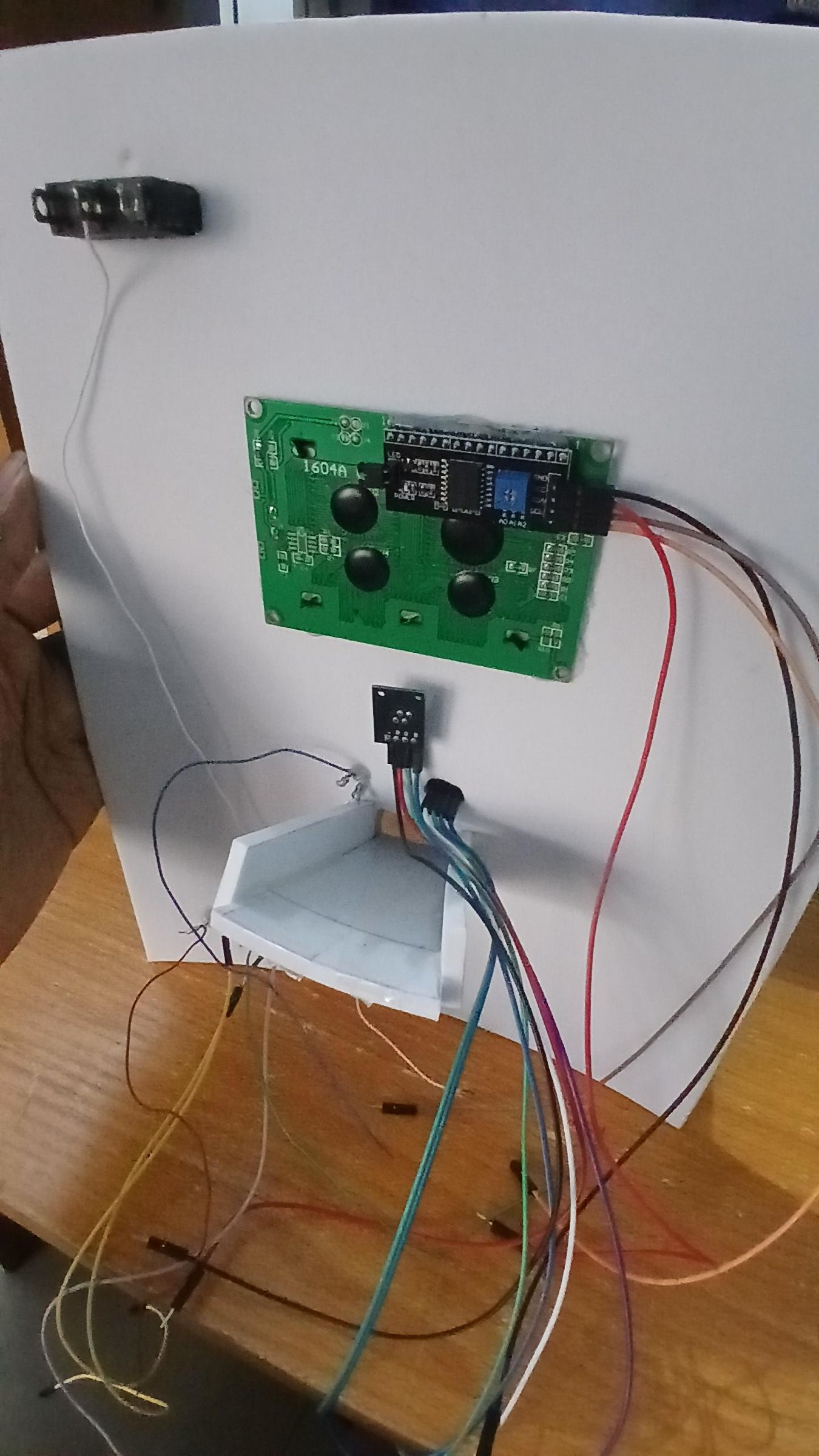
- 16×4 I2C LCD window — rectangular cutout sized to the LCD bezel; LCD runs on the shared I2C bus, SDA on GPIO 21, SCL on GPIO 22
- IR receiver window — small slot for line-of-sight to the remote, receiver on GPIO 32
A small note for anyone replicating this: an earlier prototype used an HC-SR04 ultrasonic sensor for gesture-based dispensing, which is visible in some in-progress photos as a separate mounted module. That approach was dropped in the final design — gesture/proximity-based triggering was a safety risk, since it could let a child place a hand near the dispenser slot and accidentally trigger a dose. The final firmware uses IR remote control instead (GPIO 32), so if you're following this build, you can skip the ultrasonic sensor entirely and go straight to the IR receiver.
Test-fitting before final mounting
Before soldering or gluing anything in place, dry-fit each component into its cutout: LCD with I2C backpack, RGB LED, green status LEDs and buzzer. Confirm wire routing has enough slack to reach the ESP32 inside the case.
Fabricating and Mounting the Pill Disk
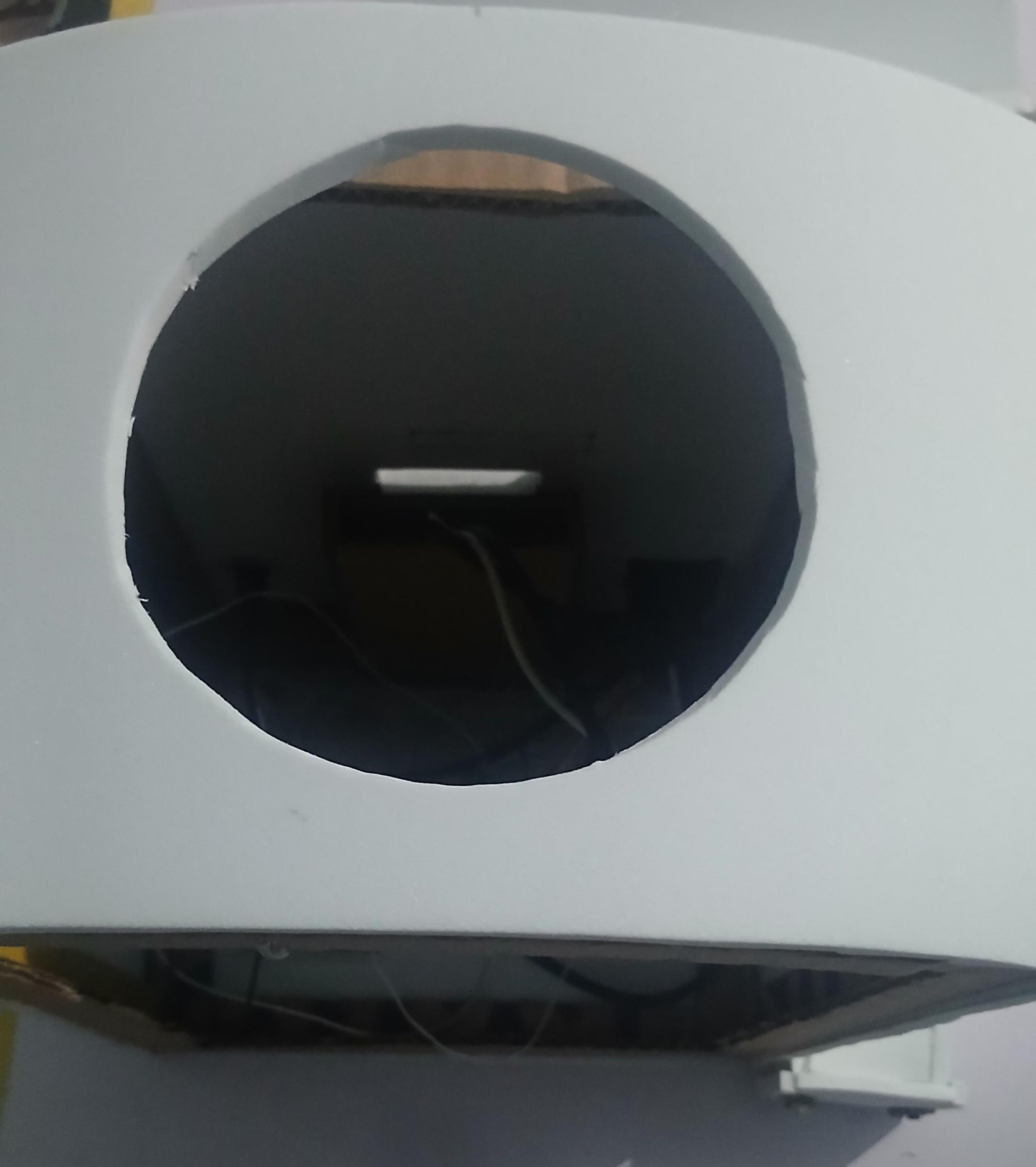

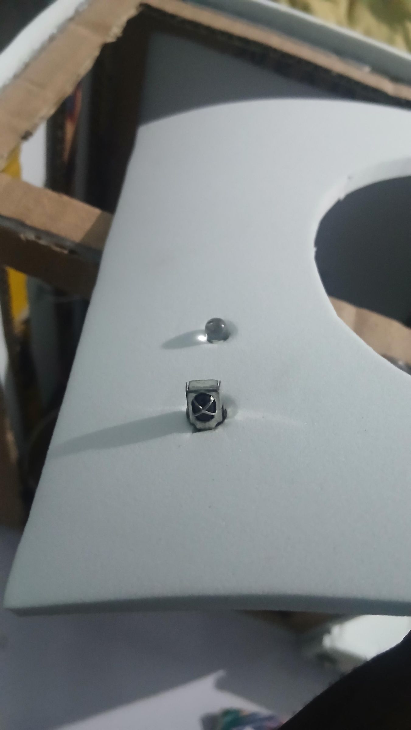
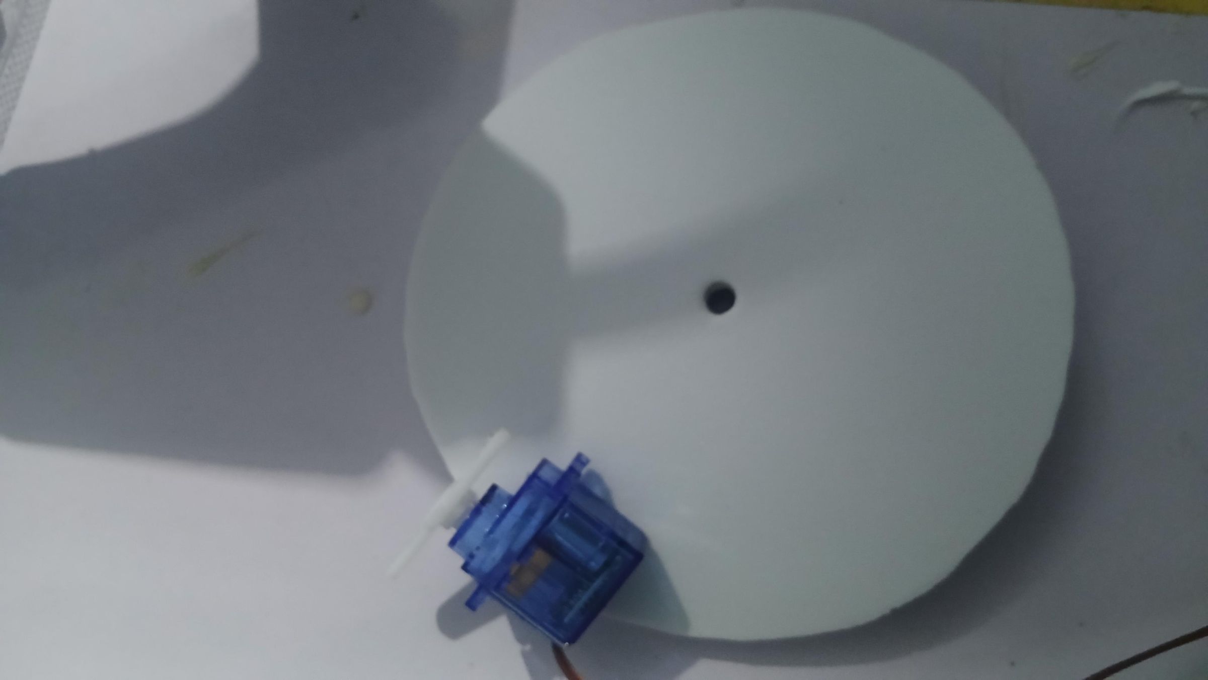
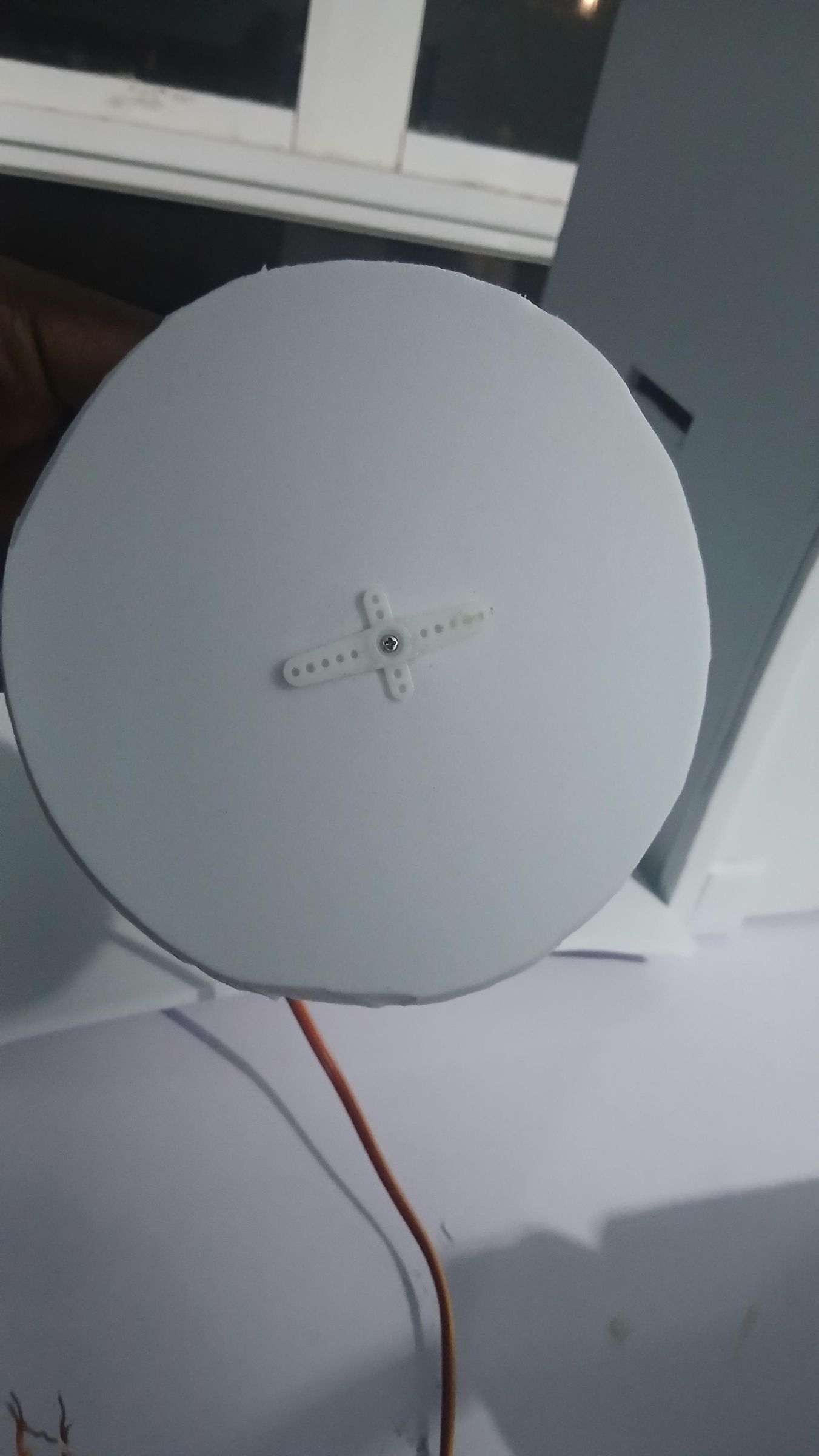
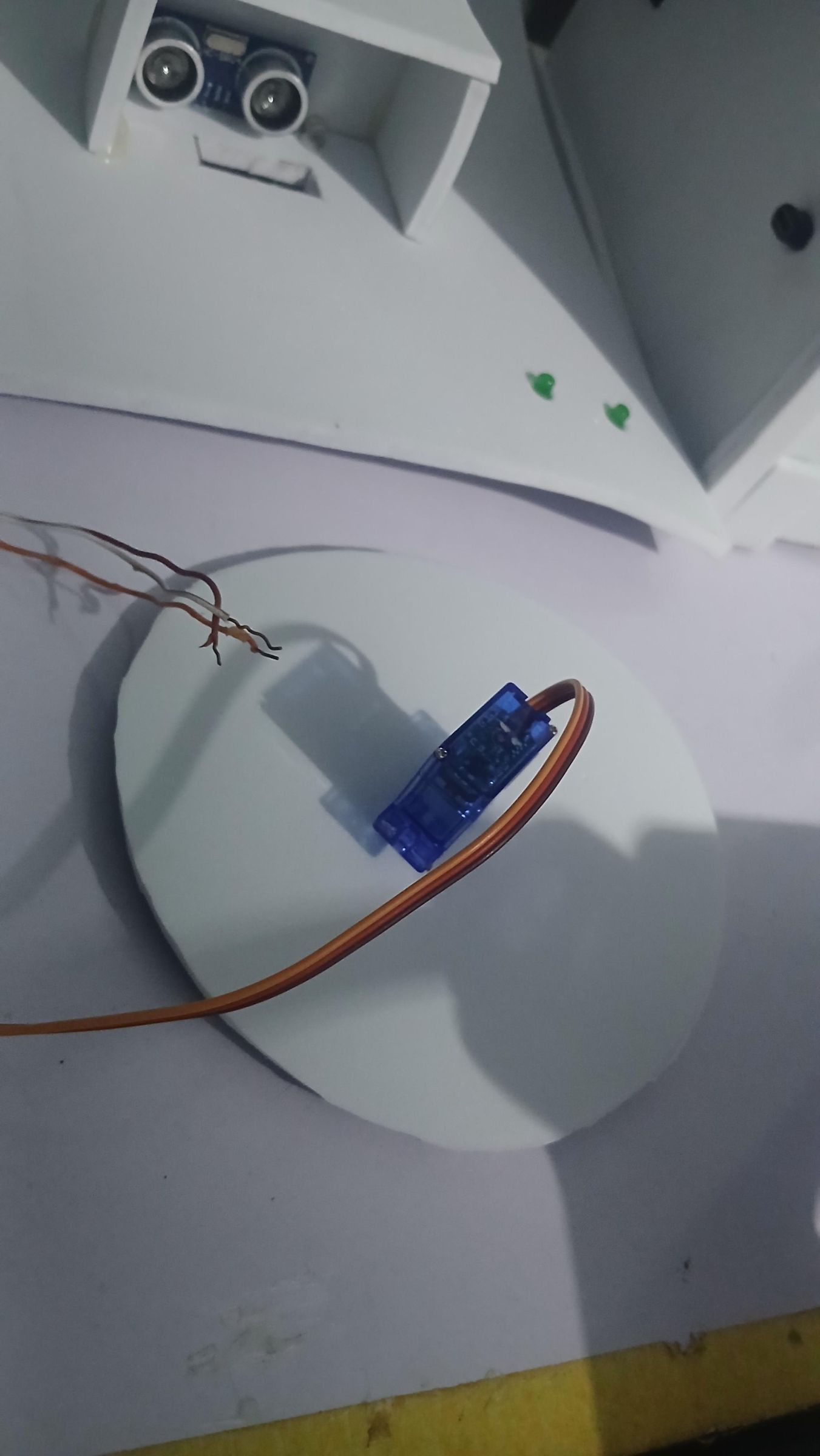
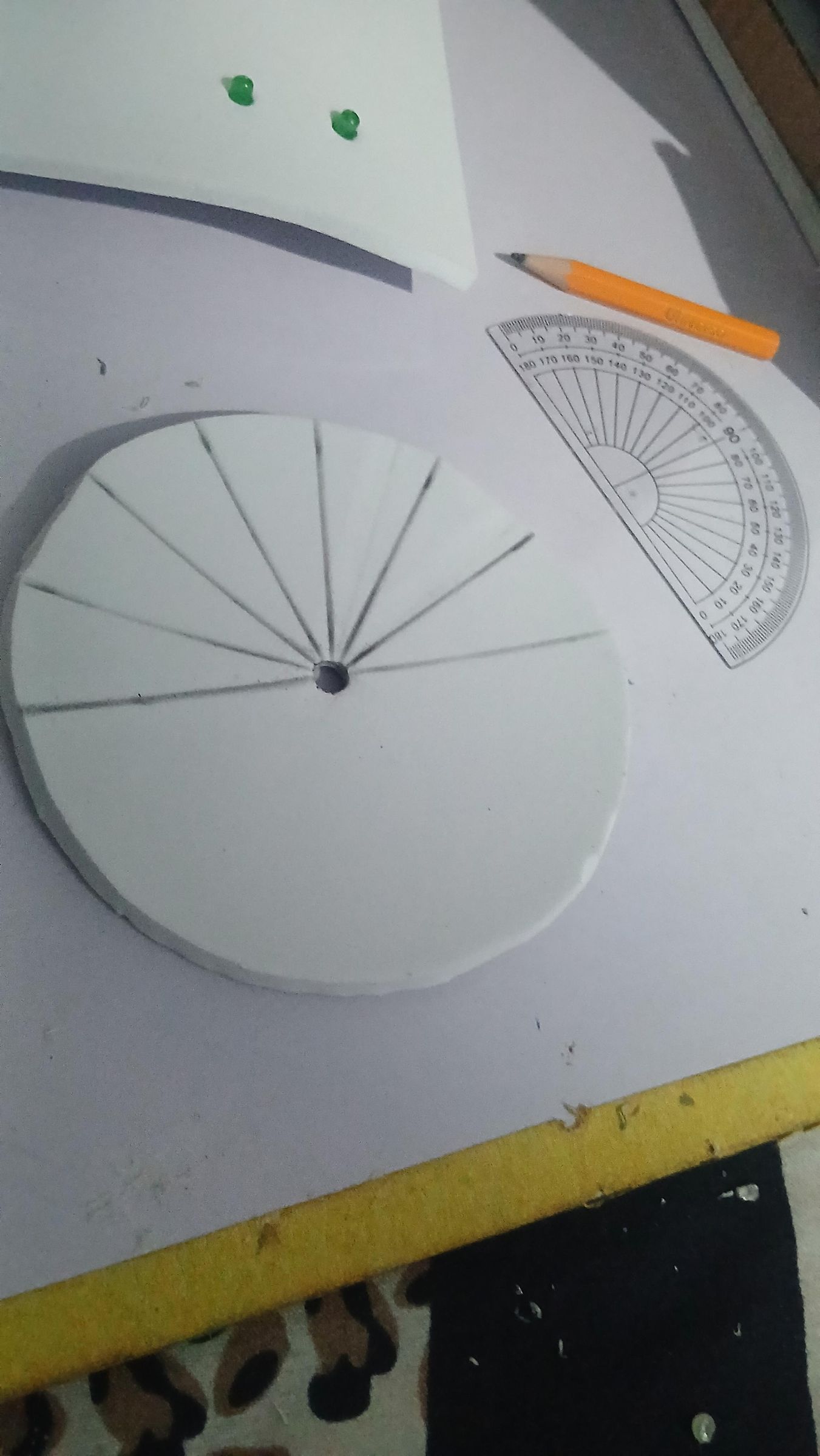
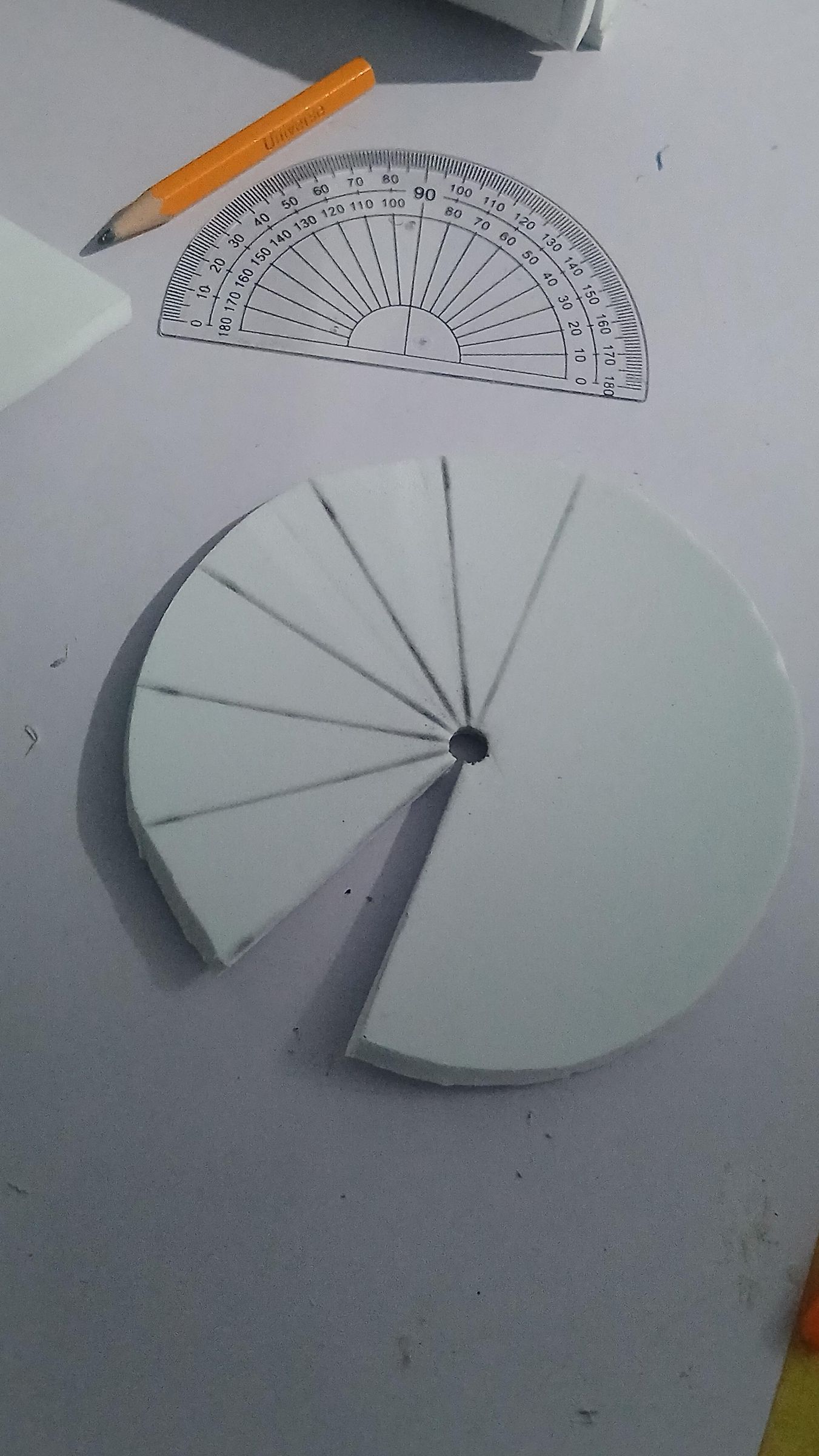
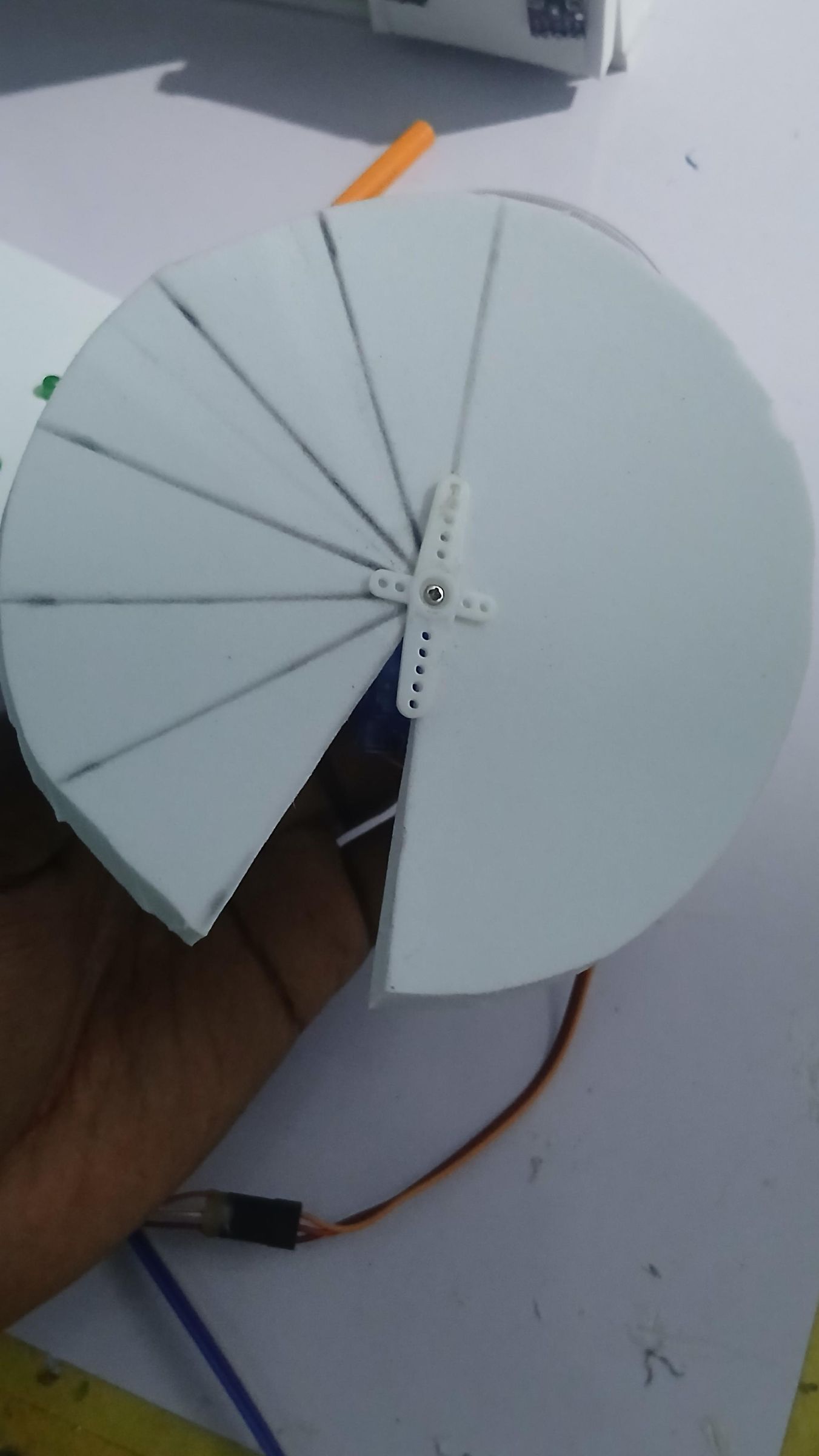
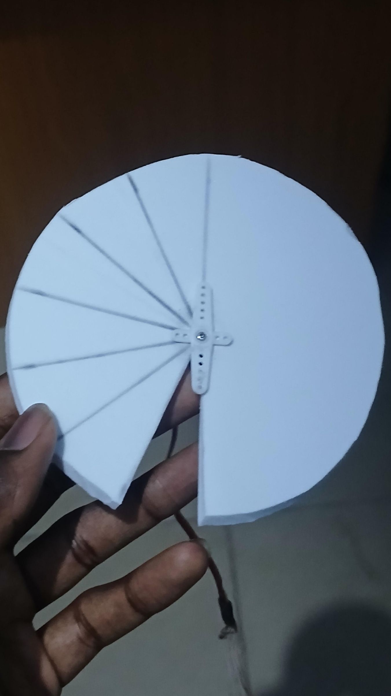
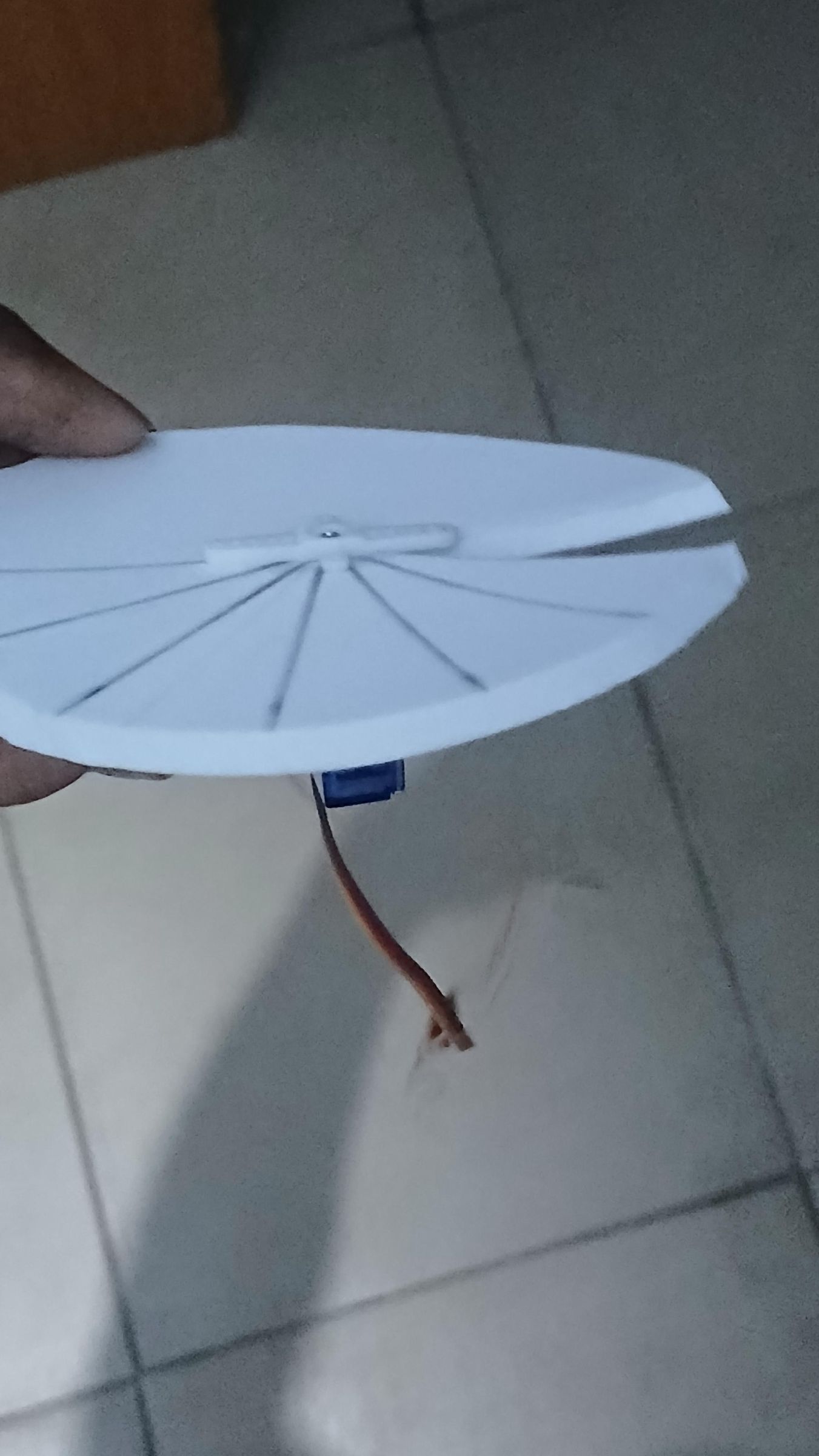
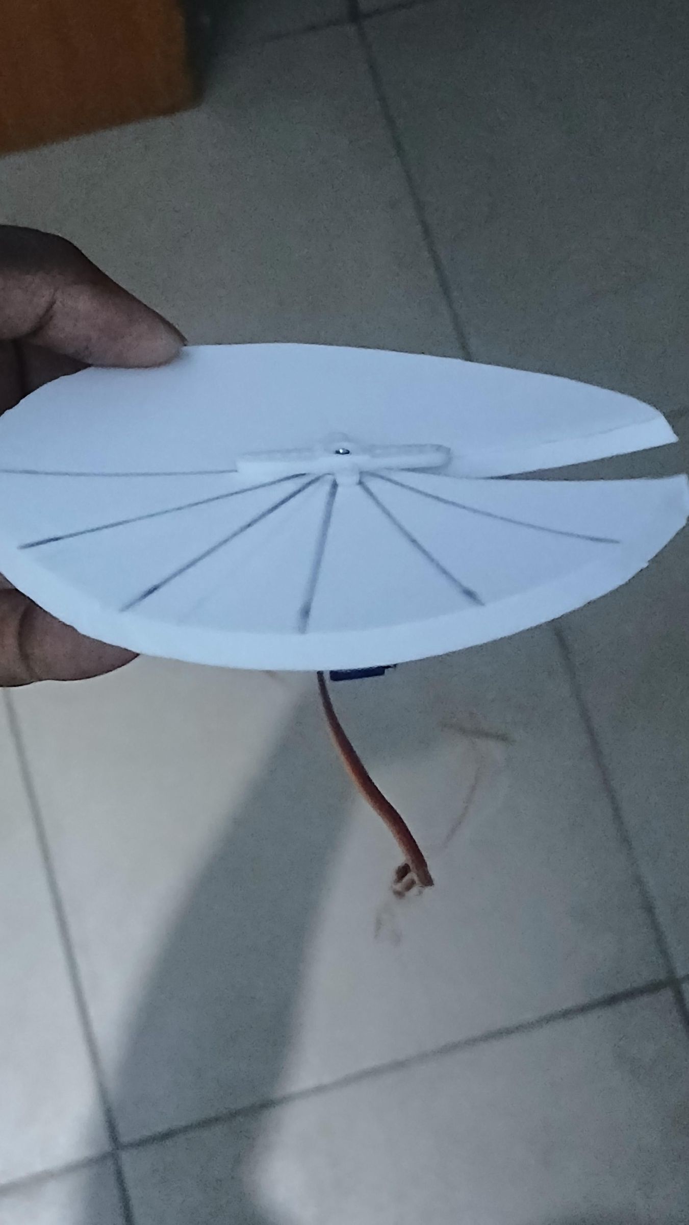
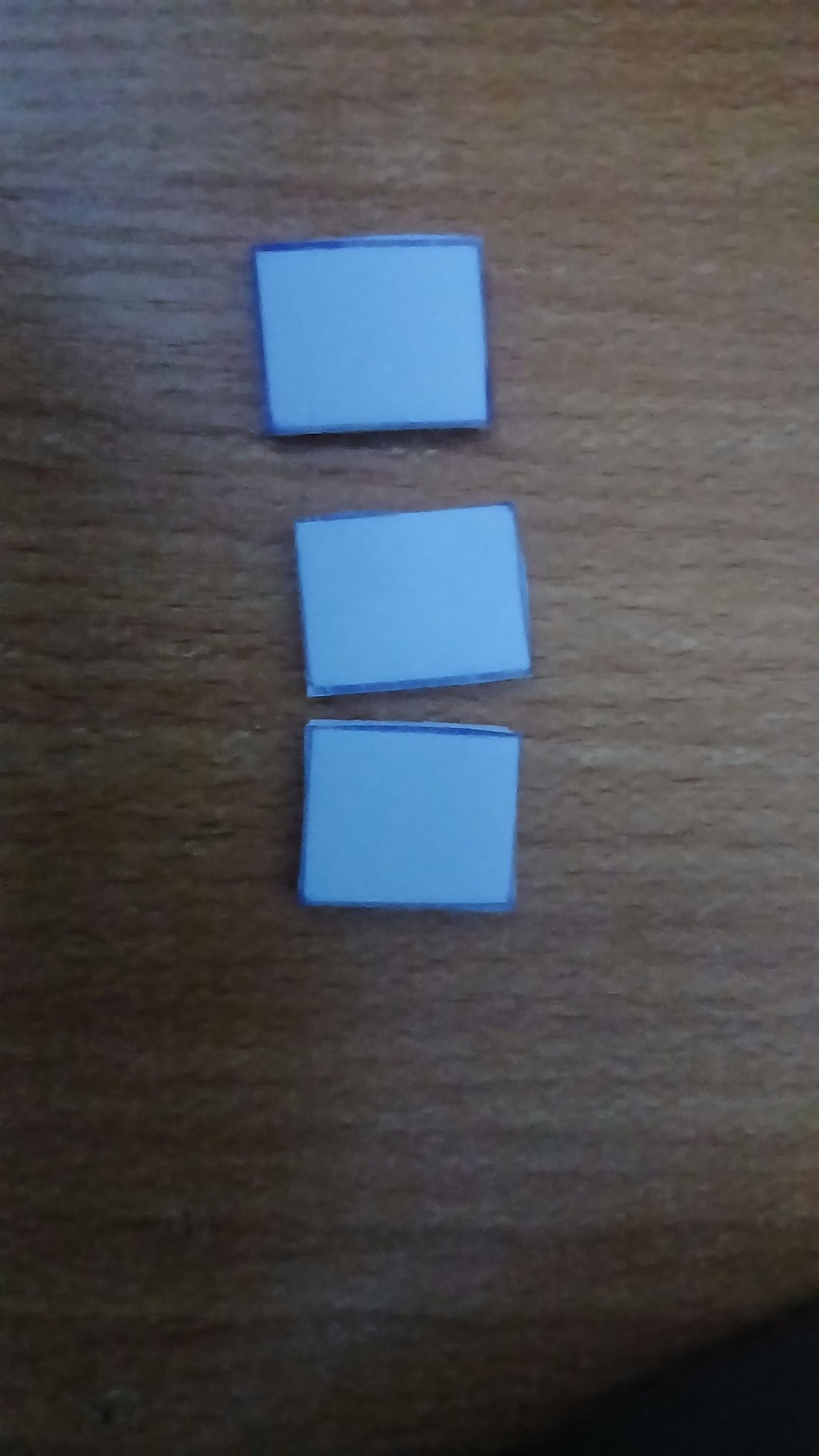
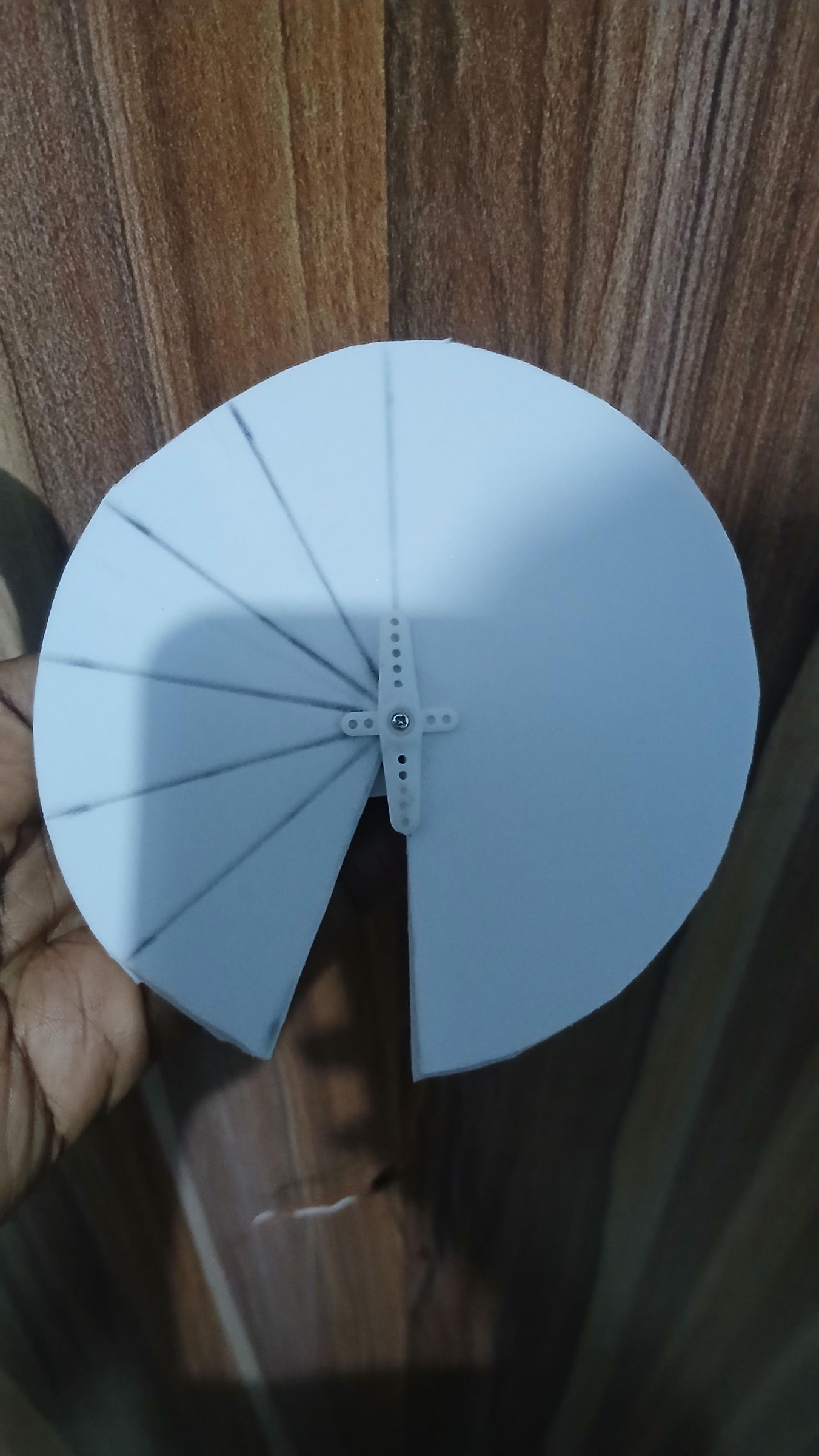
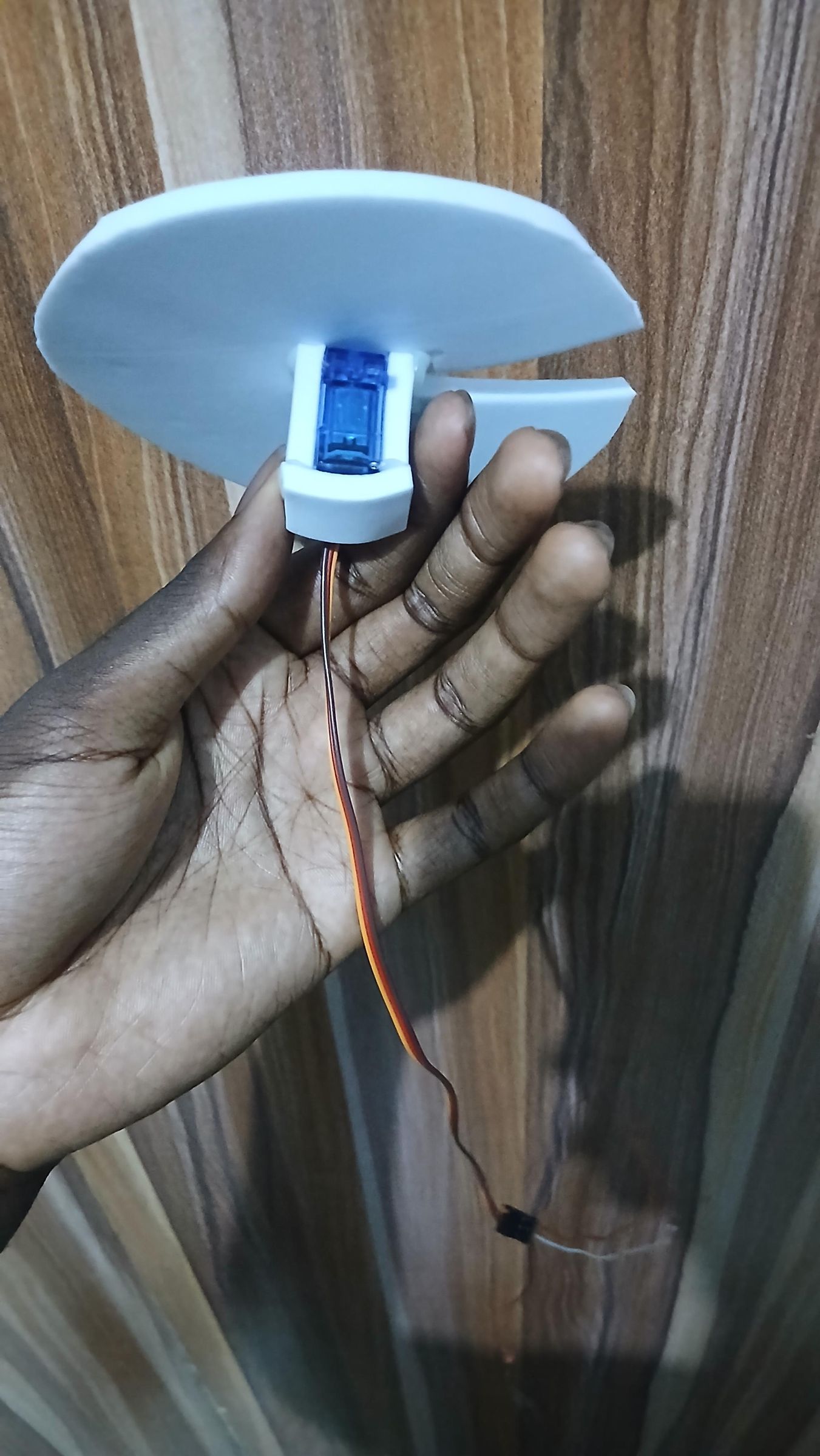
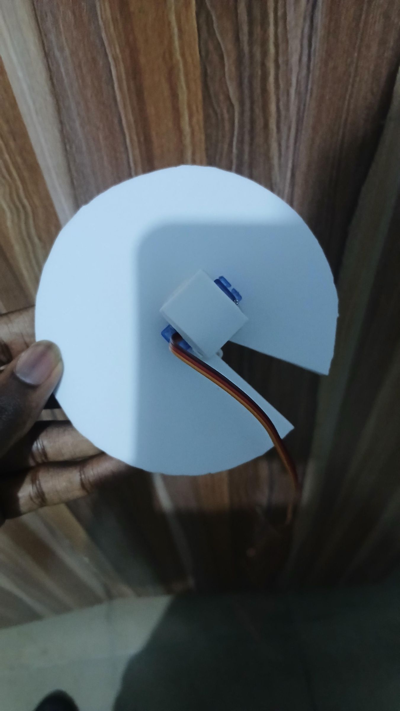
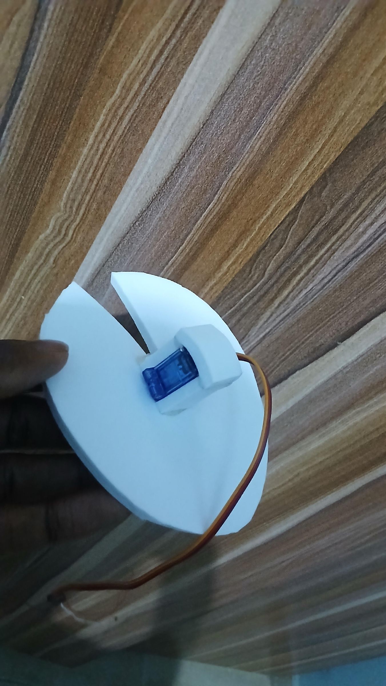
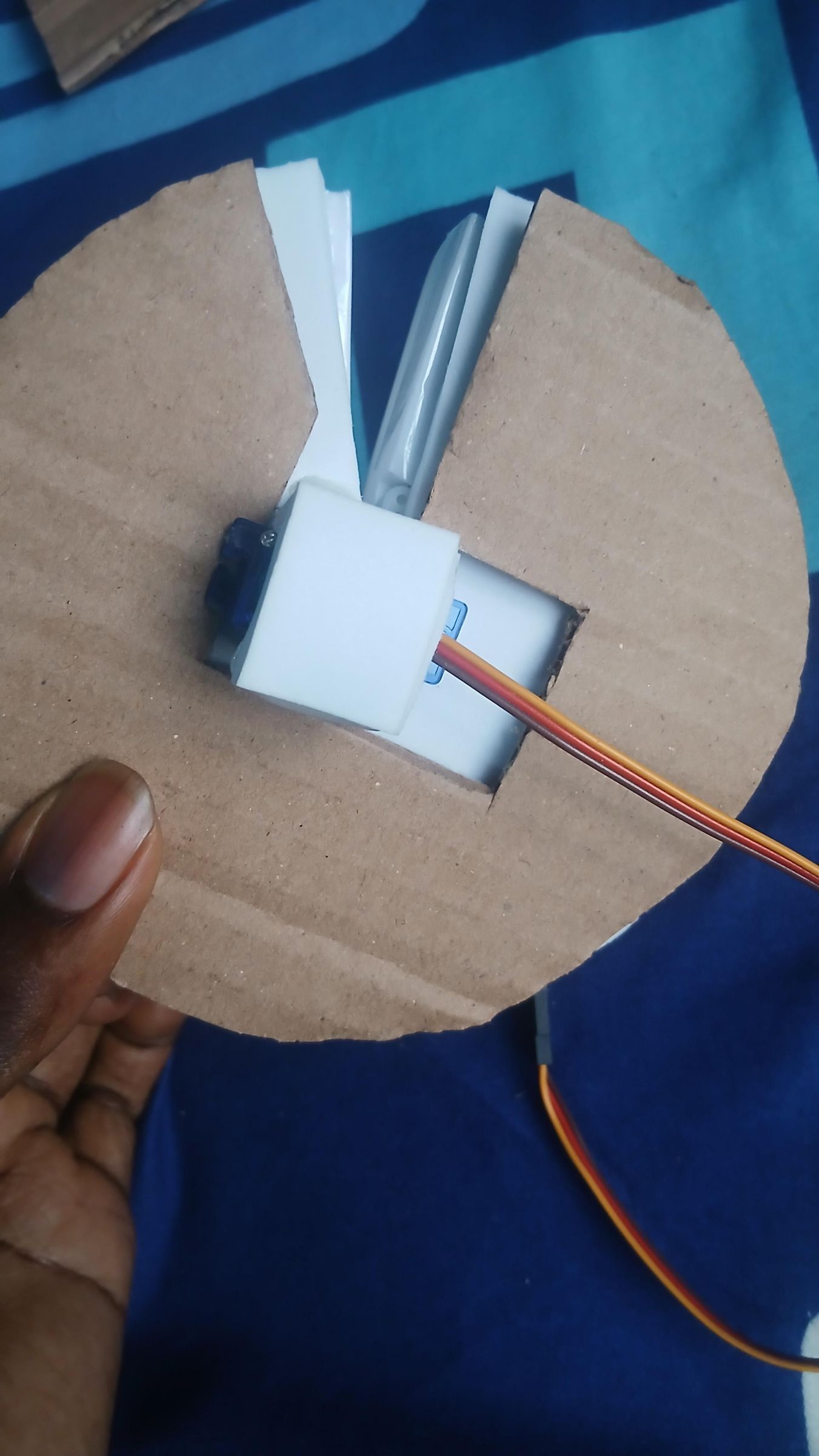
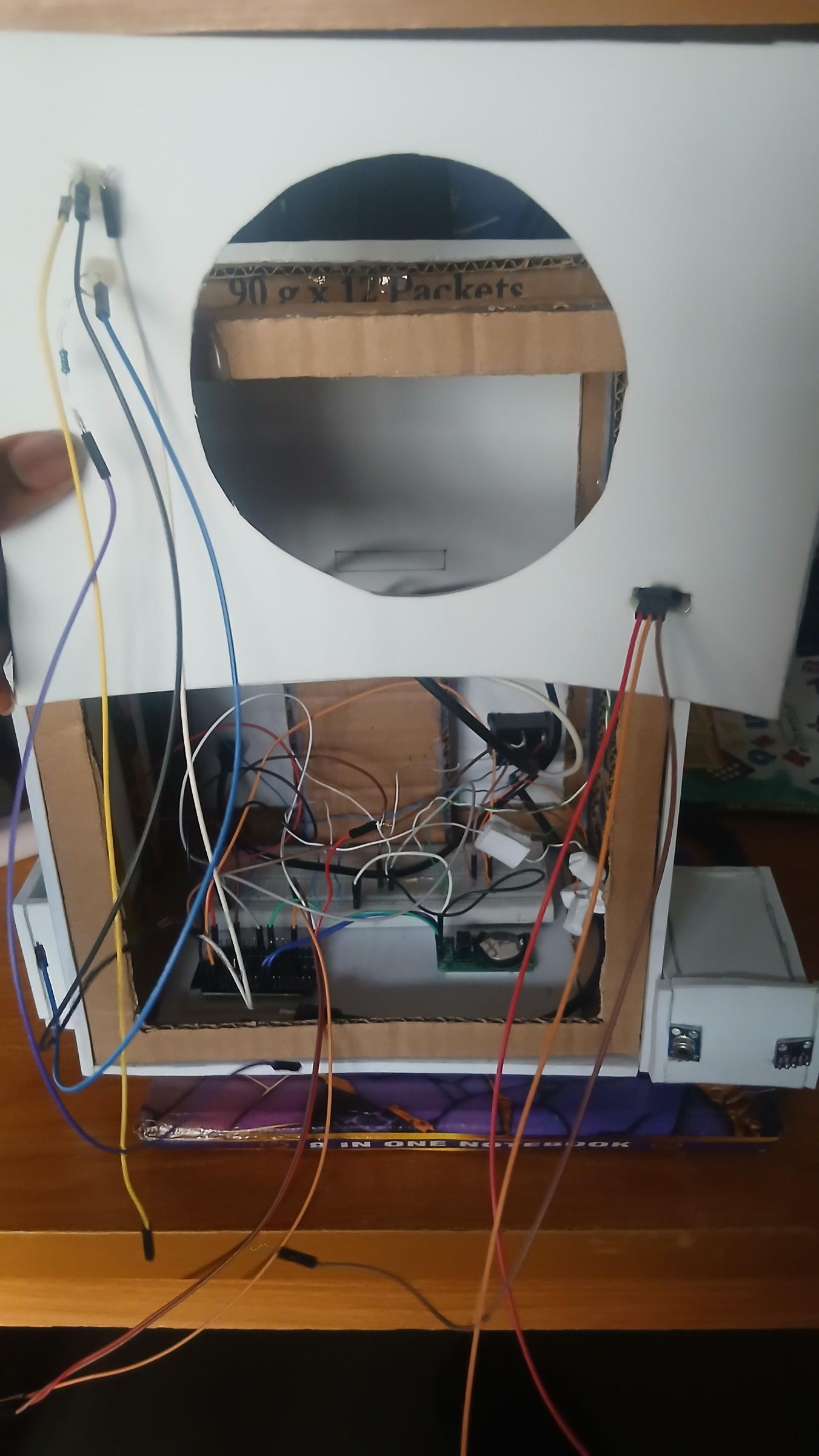
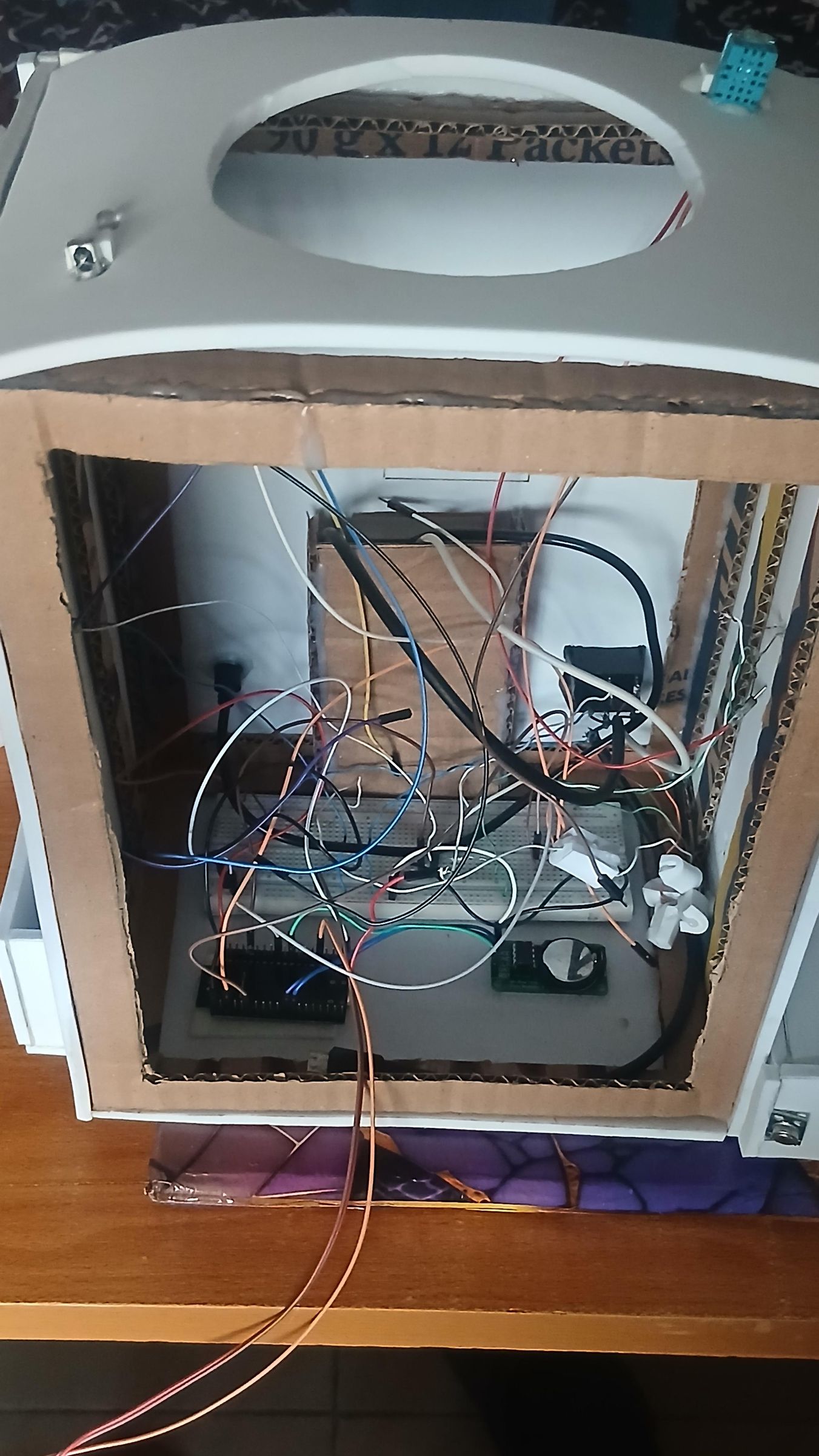
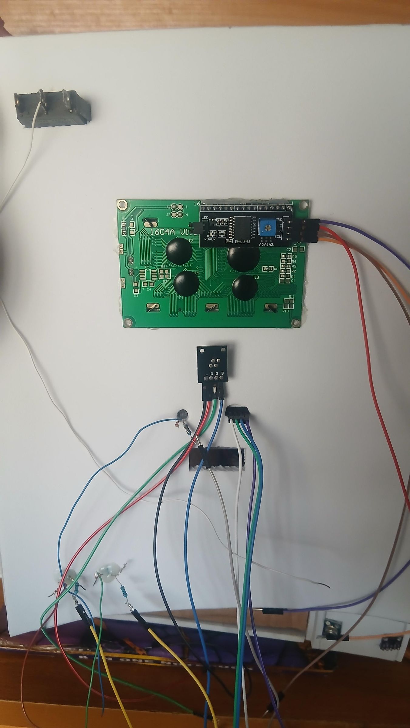
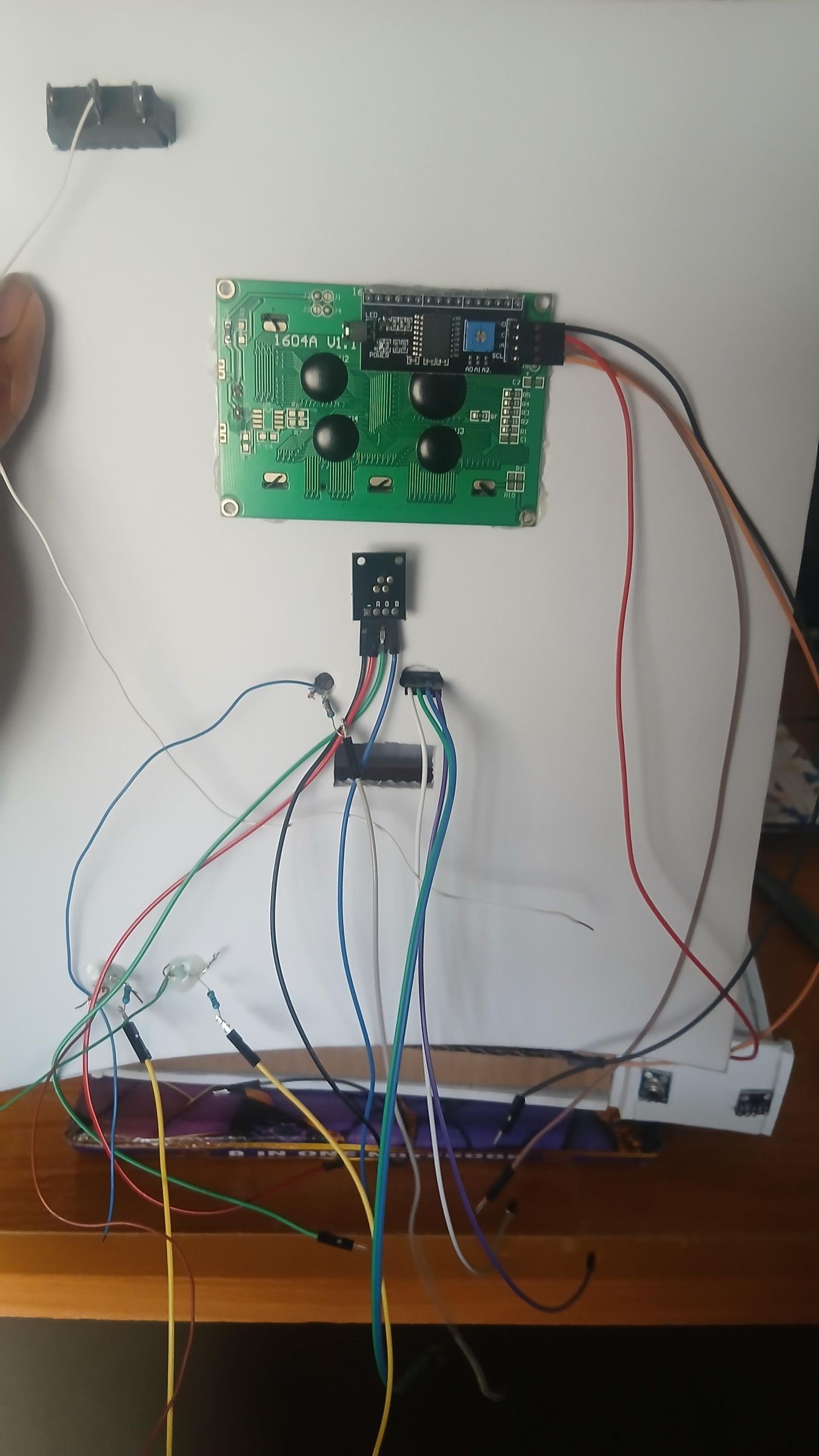
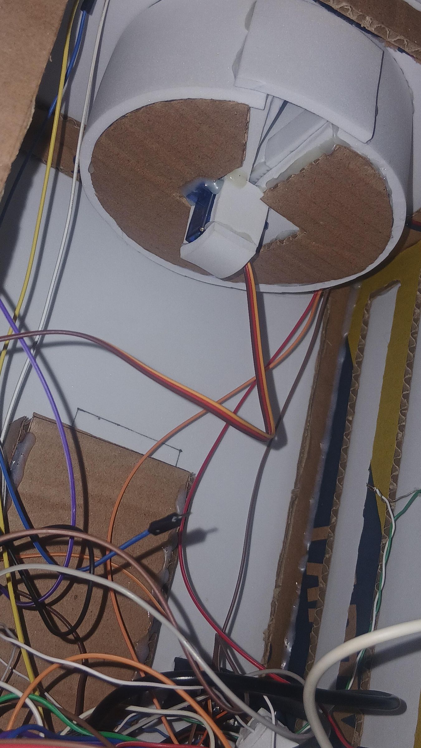
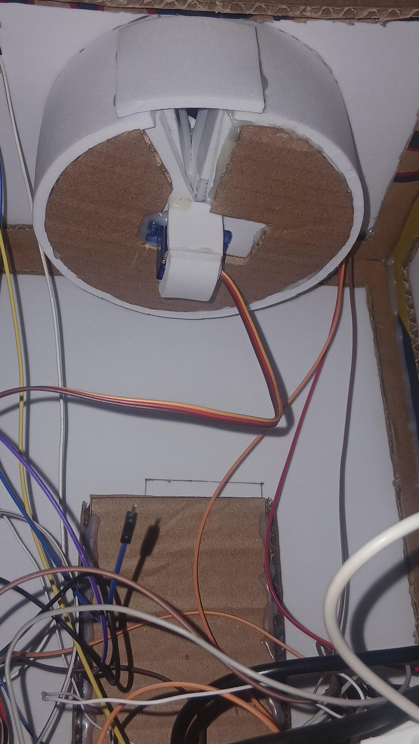
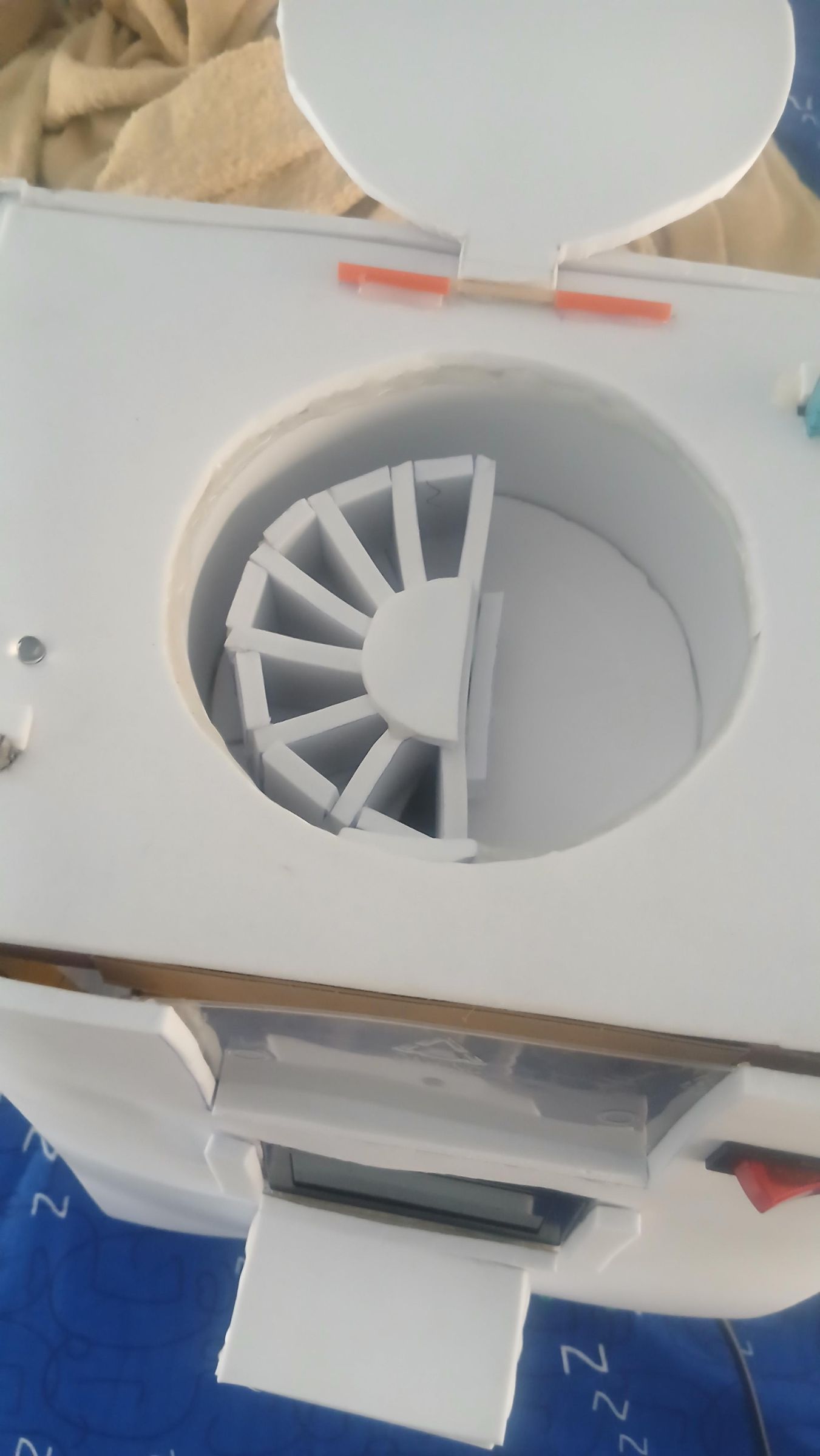
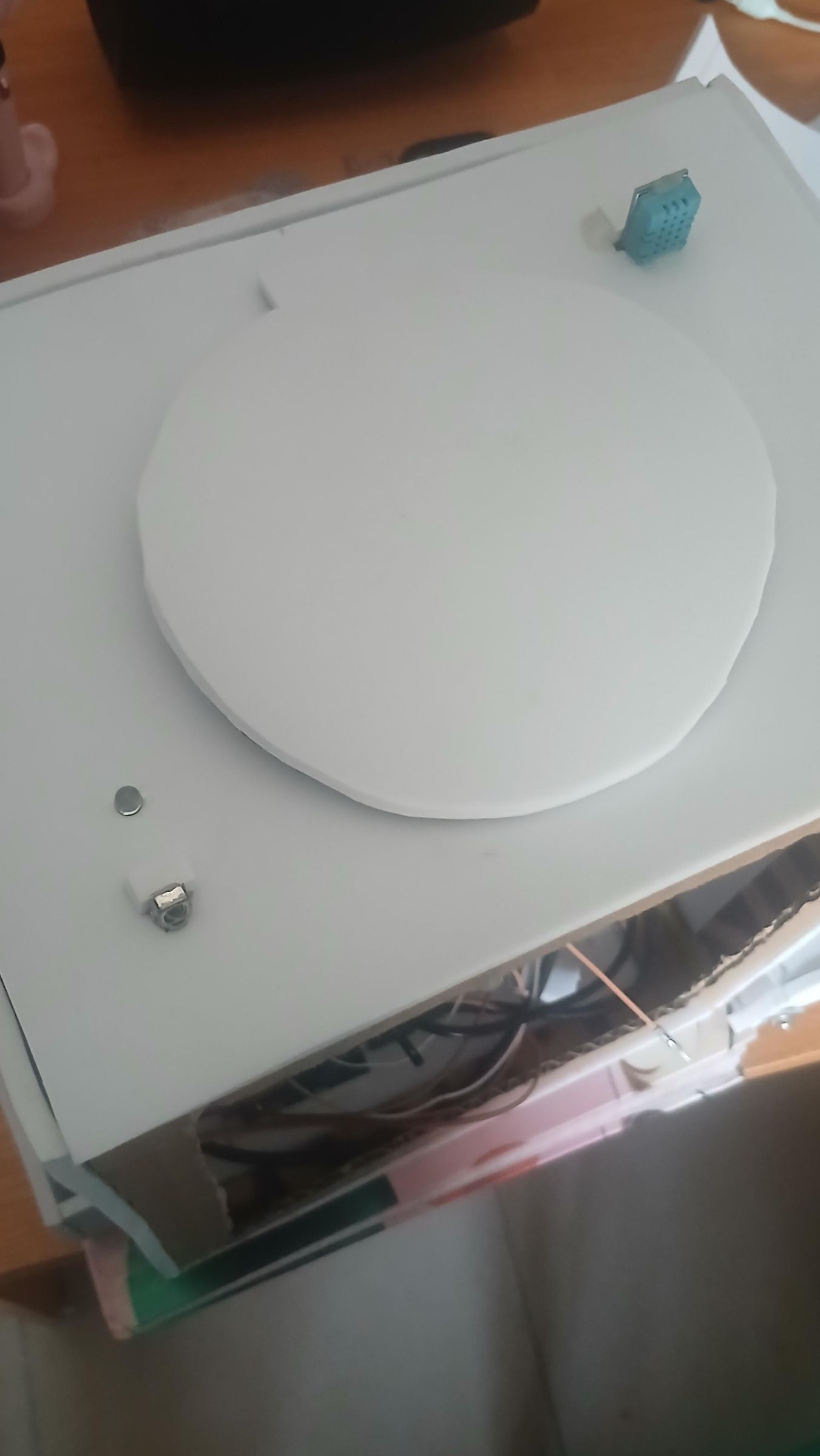
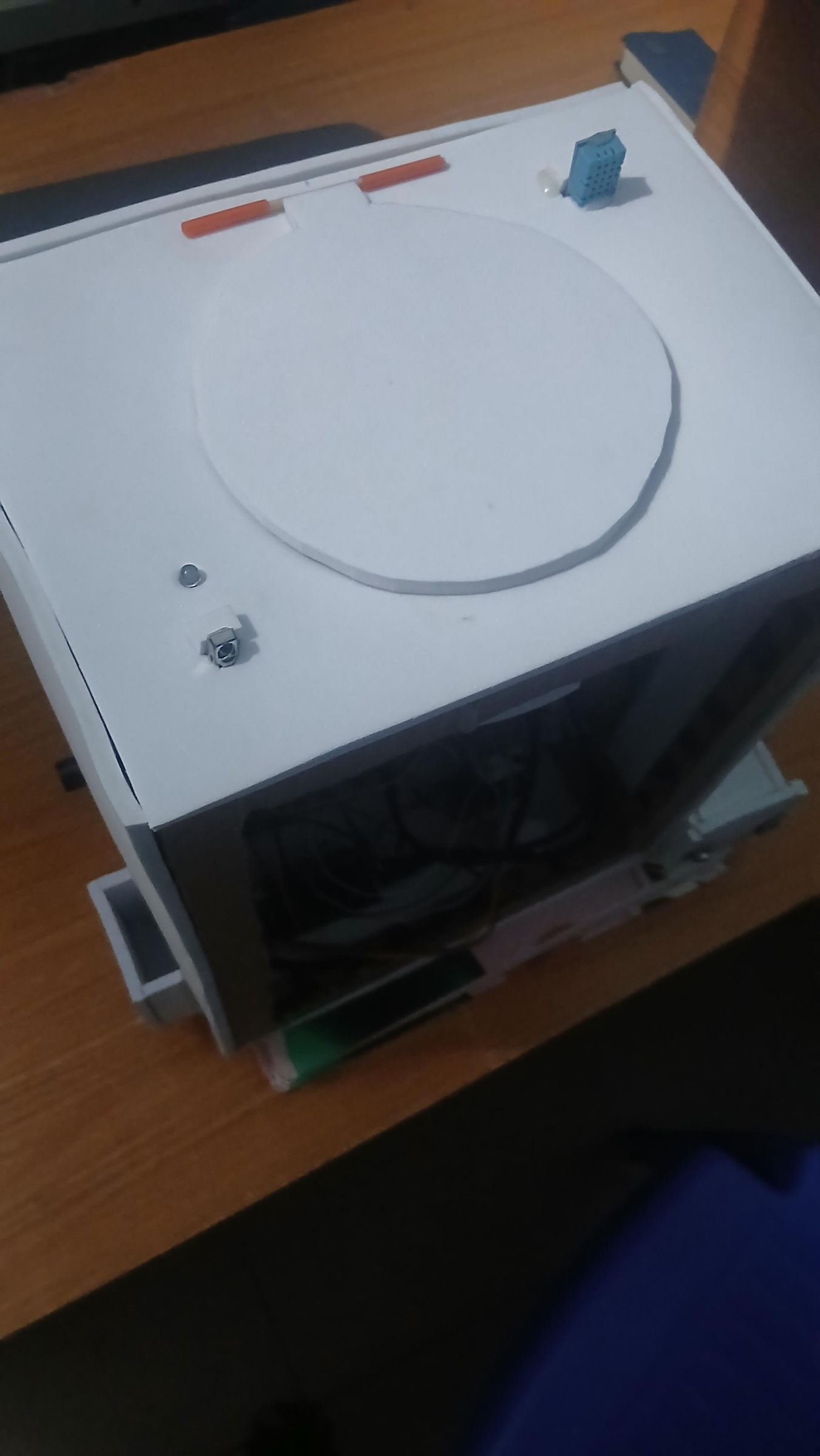
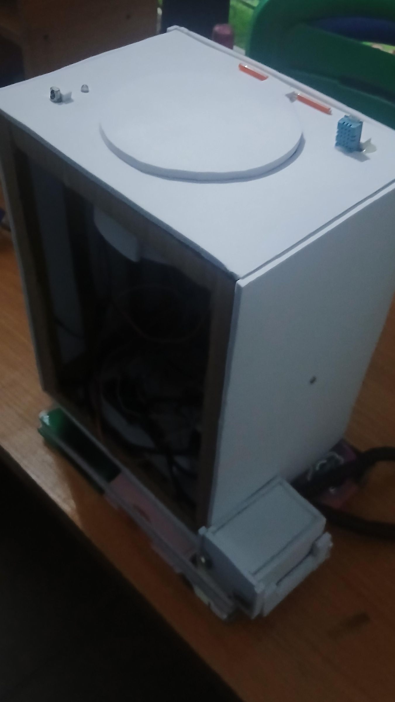
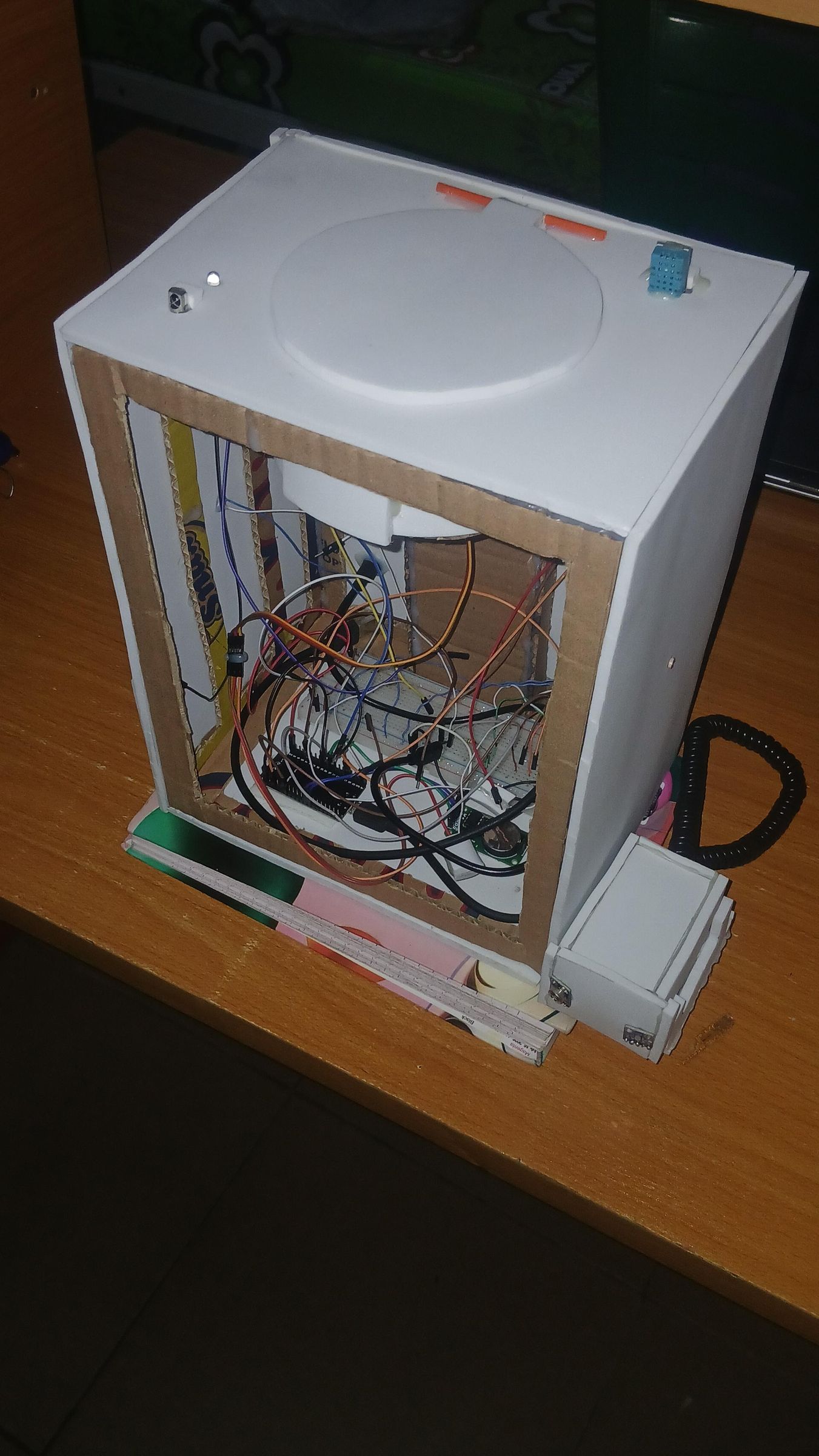
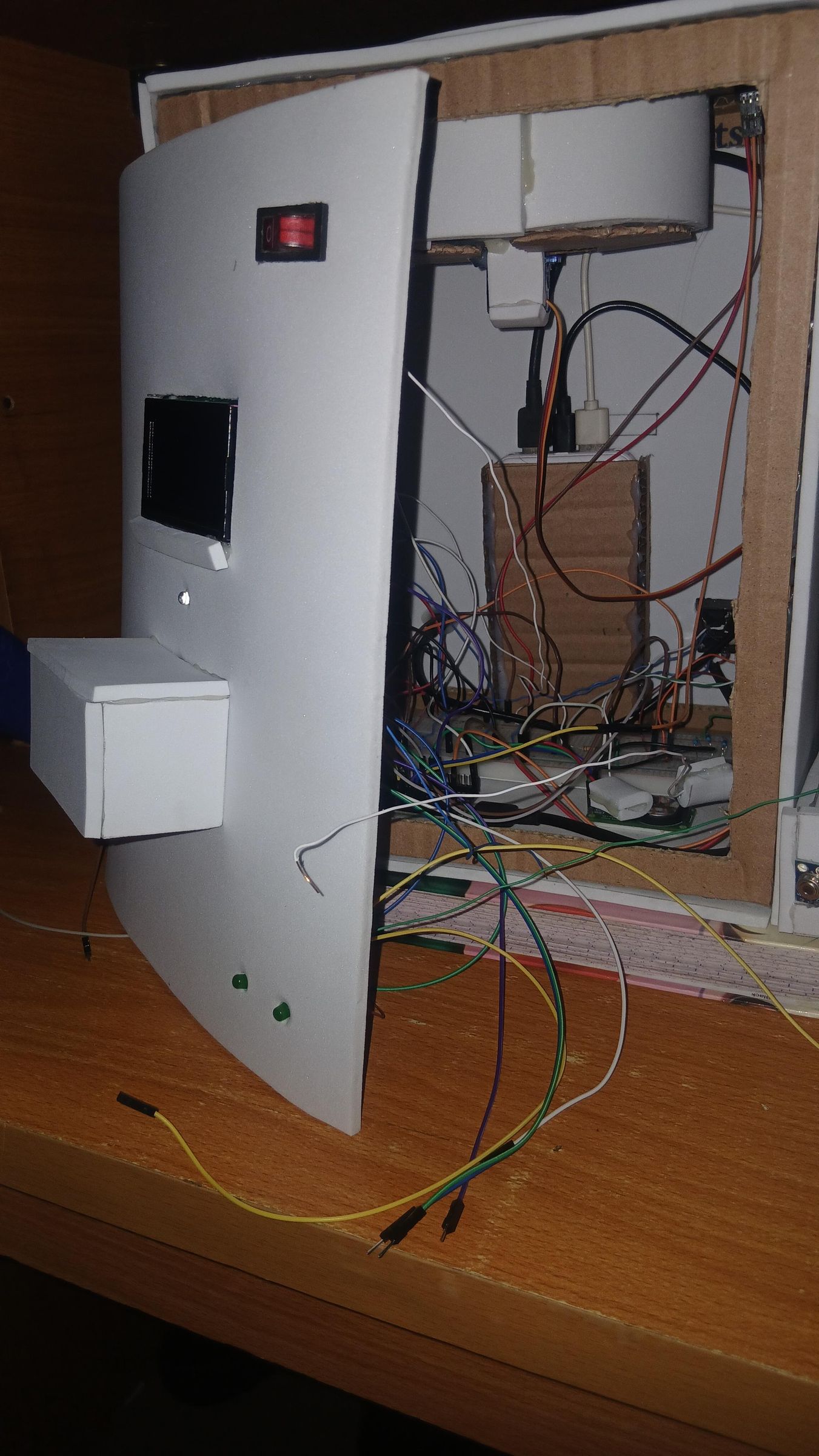
This step covers cutting the circular opening in the top panel, building the pill dispensing disk, mounting the SG90 servo beneath it, and seating the disk in place — the heart of the entire dispensing mechanism.
Cutting the circular opening in the top panel
With your compass-marked circle from Step 4 as your guide, carefully cut out the circular opening in the top panel. Work slowly around the curve — a craft knife or jigsaw both work, but if you are cutting by hand, score the line several times before cutting all the way through to keep the edge clean. The cut disc can be saved as a template or test piece.
Making the pill disk
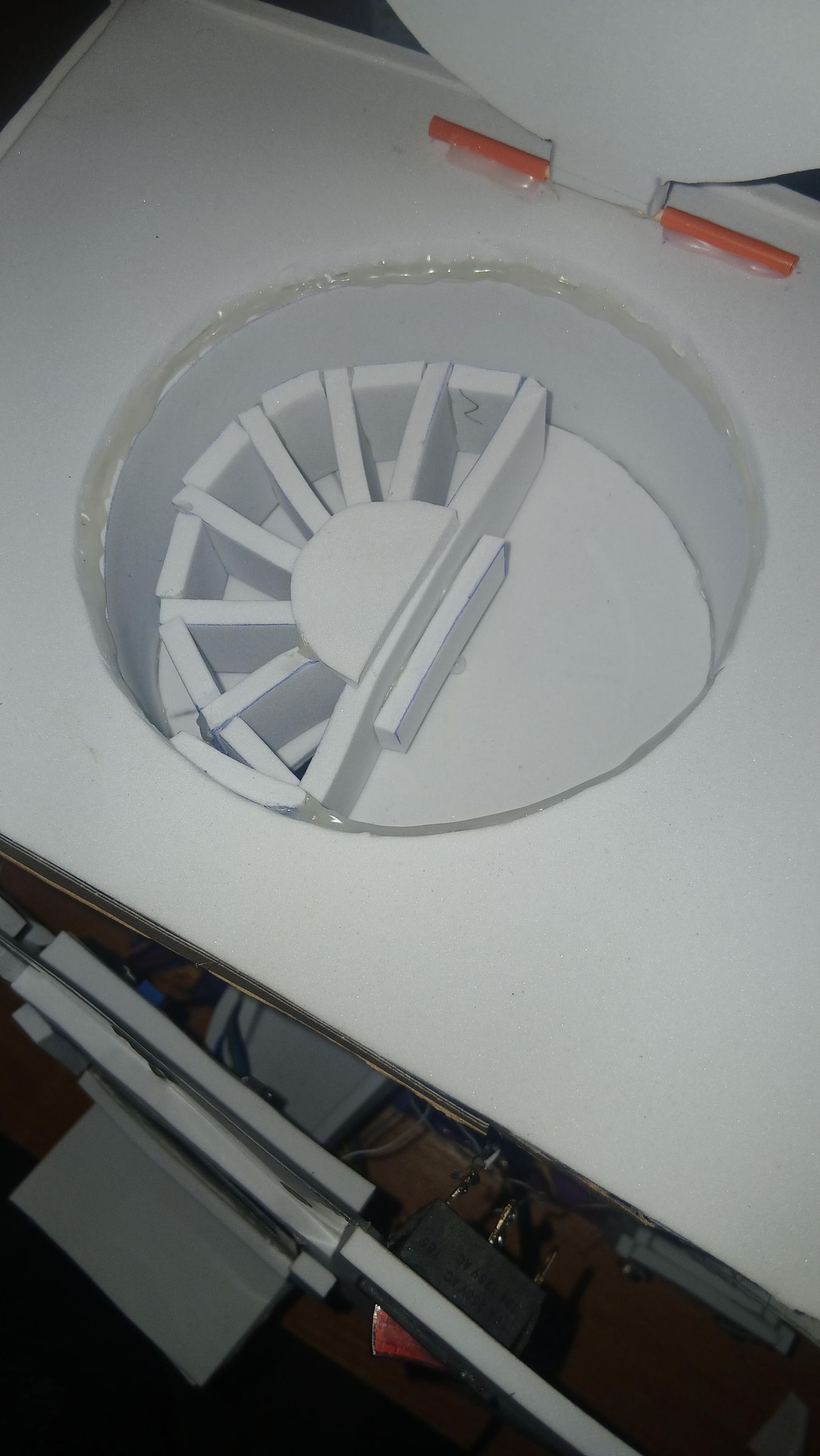
Cut a fresh circular disc from your sheet material to match the opening diameter. This disc sits inside the circular opening and rotates above a dispense slot cut into the top panel.
The disk has 6 active compartments plus a home position — 7 positions total — driven by the SG90 servo on GPIO 13. The firmware moves the servo in direct angle jumps using precise pulse widths. The home resting position starts at 0° (544 µs). From there the servo steps through Compartment 1 at 874 µs (~35°), Compartment 2 at 1204 µs (~67°), Compartment 3 at 1472 µs (~92°), Compartment 4 at 1761 µs (~119°), Compartment 5 at 2029 µs (~145°), and Compartment 6 at 2215 µs (~162°).
The full working travel of the disk is 0° to ~162°. Note that the compartment divisions are not perfectly equal in arc size — this is intentional, as the foamboard wall thickness used to build the dividers takes up physical space within each slot, so the angular spacing between positions was adjusted during fabrication to account for the material thickness and ensure each compartment aligns cleanly with the dispense slot at its target position. Using a protractor, mark the divisions on your disk at 0°, ~35°, ~67°, ~92°, ~119°, ~145°, and ~162°, then adjust slightly during fitting if your foamboard thickness differs from the original build.
Mounting the SG90 servo
The SG90 servo mounts underneath the disk, centered below it, with its output shaft pointing upward through a small central hole in the disk. A servo bracket or housing cut from scrap material holds the servo body fixed while the shaft — and the disk attached to it — rotates freely. The servo's three-wire lead (signal on GPIO 13, power on 5V, ground on GND) runs down through the enclosure to the ESP32. In the firmware the servo is initialized with setPeriodHertz(50) and attach(13, 500, 2400) which sets the full travel range. Make sure the servo horn is firmly attached to the disk center before closing up the top panel.
Seating the disk in the opening
Lower the disk-and-servo assembly into the circular opening from above so the disk sits flush with or just above the top panel surface. The servo body fixes to the underside of the top panel using a mount bracket. Route the servo wire down into the enclosure interior. The DHT11 temperature and humidity sensor (GPIO 4) also mounts on the top panel at this stage for ambient environment monitoring — its position on top gives it good airflow away from heat-producing components inside the case.
Test before sealing
Before gluing the top panel down permanently, power the system and trigger a dispensing sequence via the IR remote. Confirm the servo steps the disk cleanly through all 6 compartments and returns smoothly to home at 0°. It is far easier to adjust the servo mount position now than after the top panel is sealed.
Internal Wiring, Final Assembly, and First Power-On
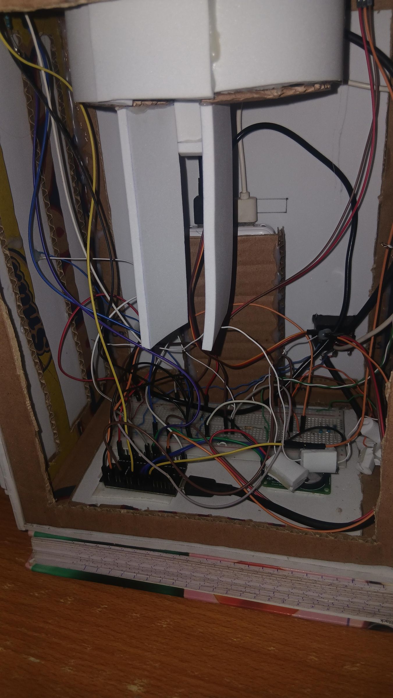
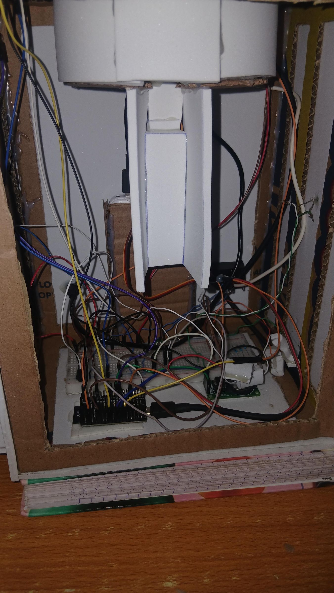
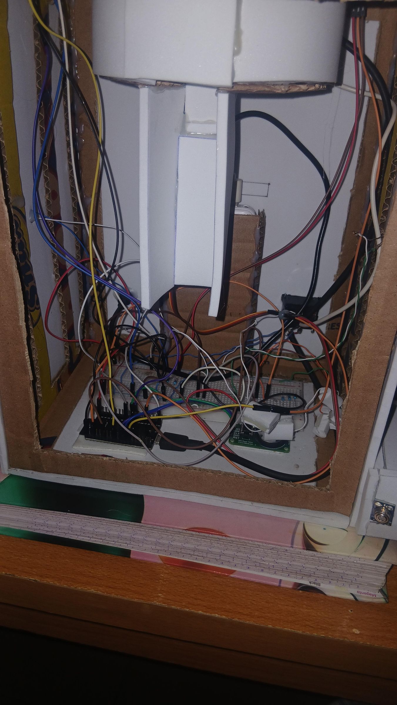
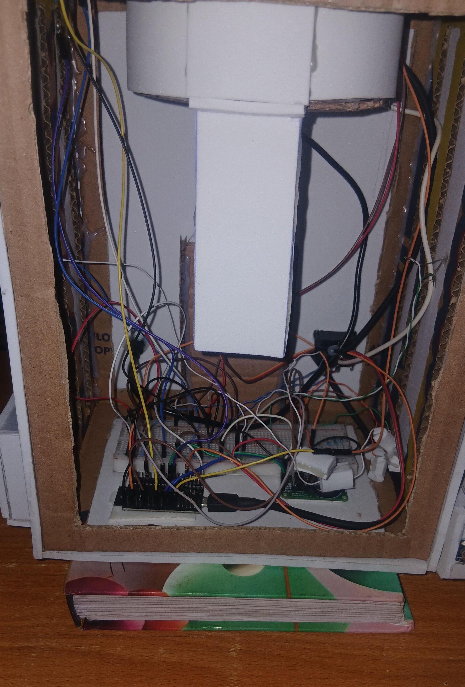
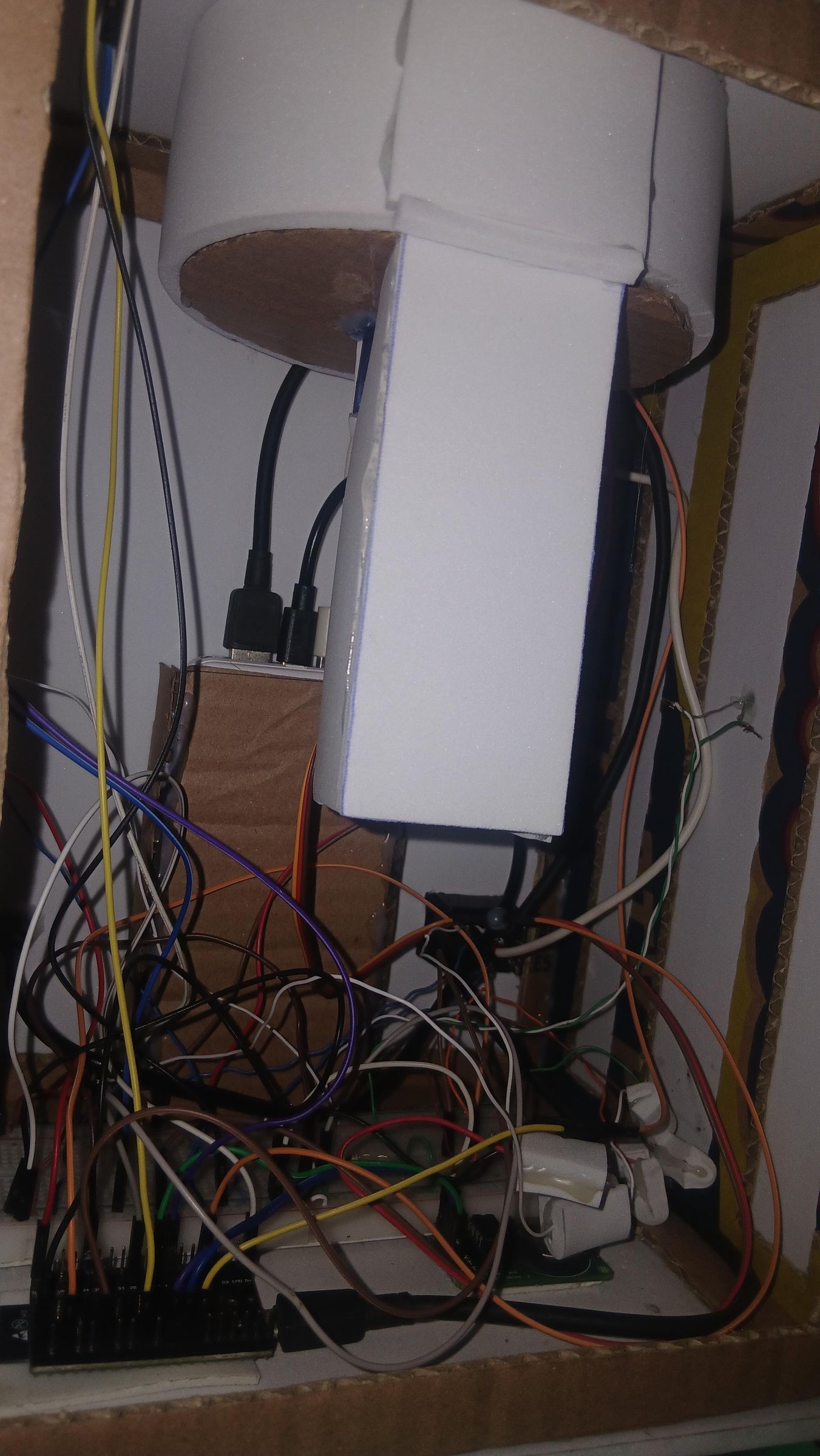
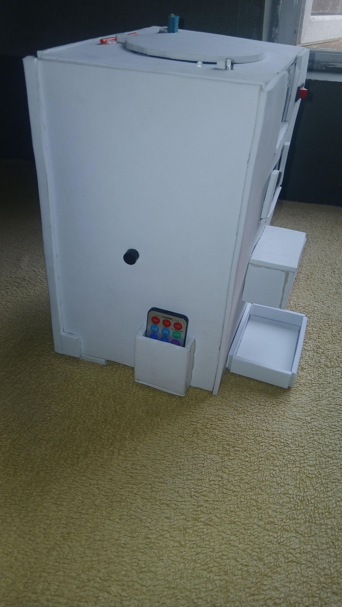
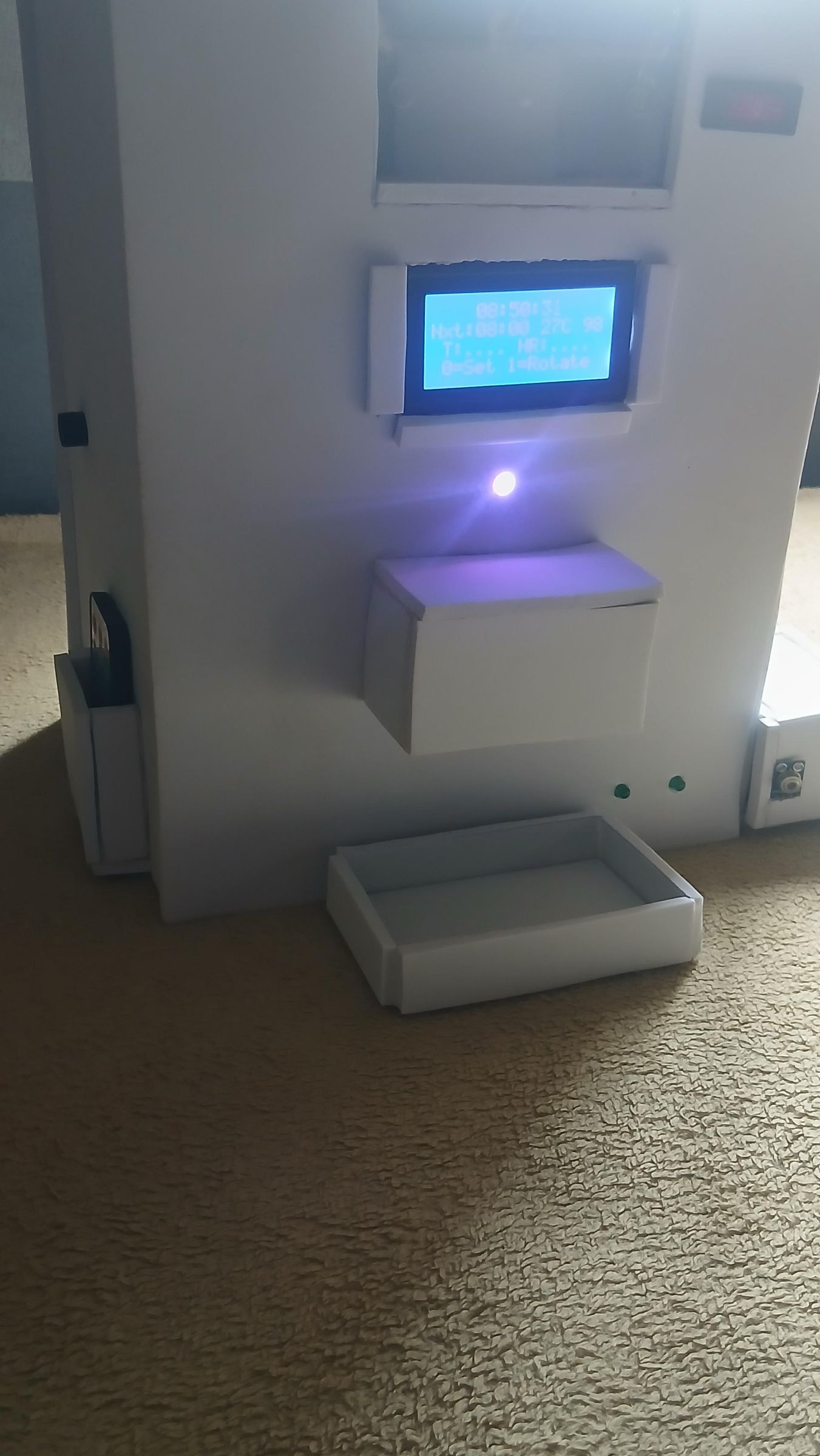
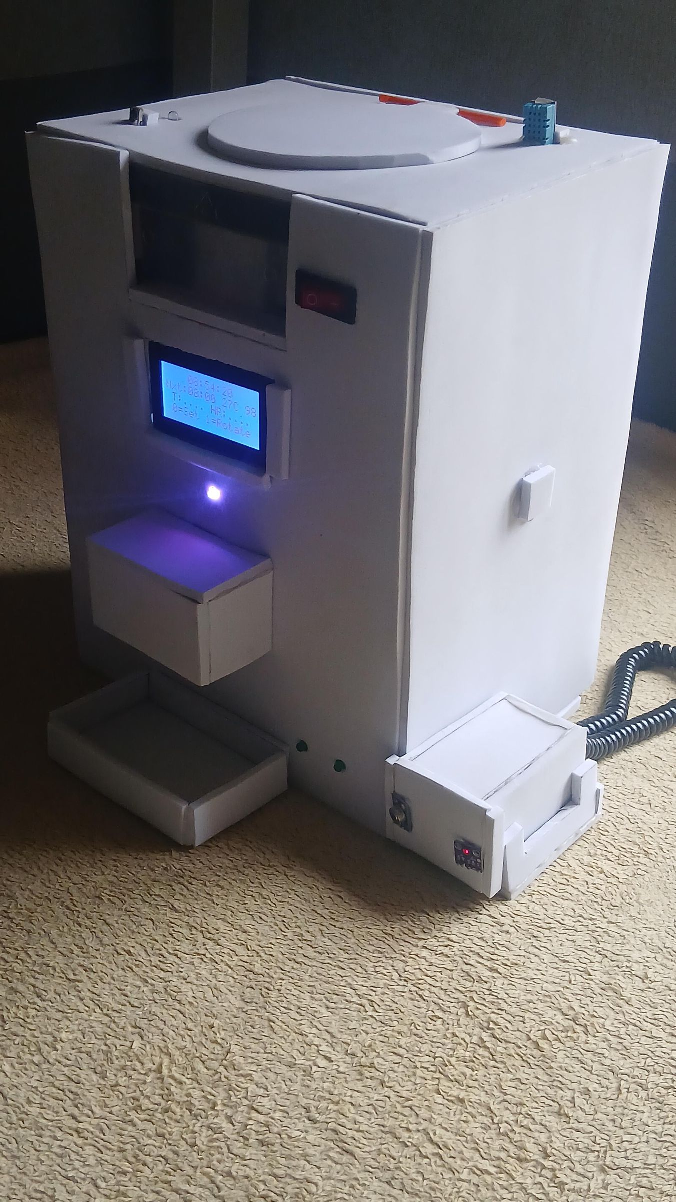
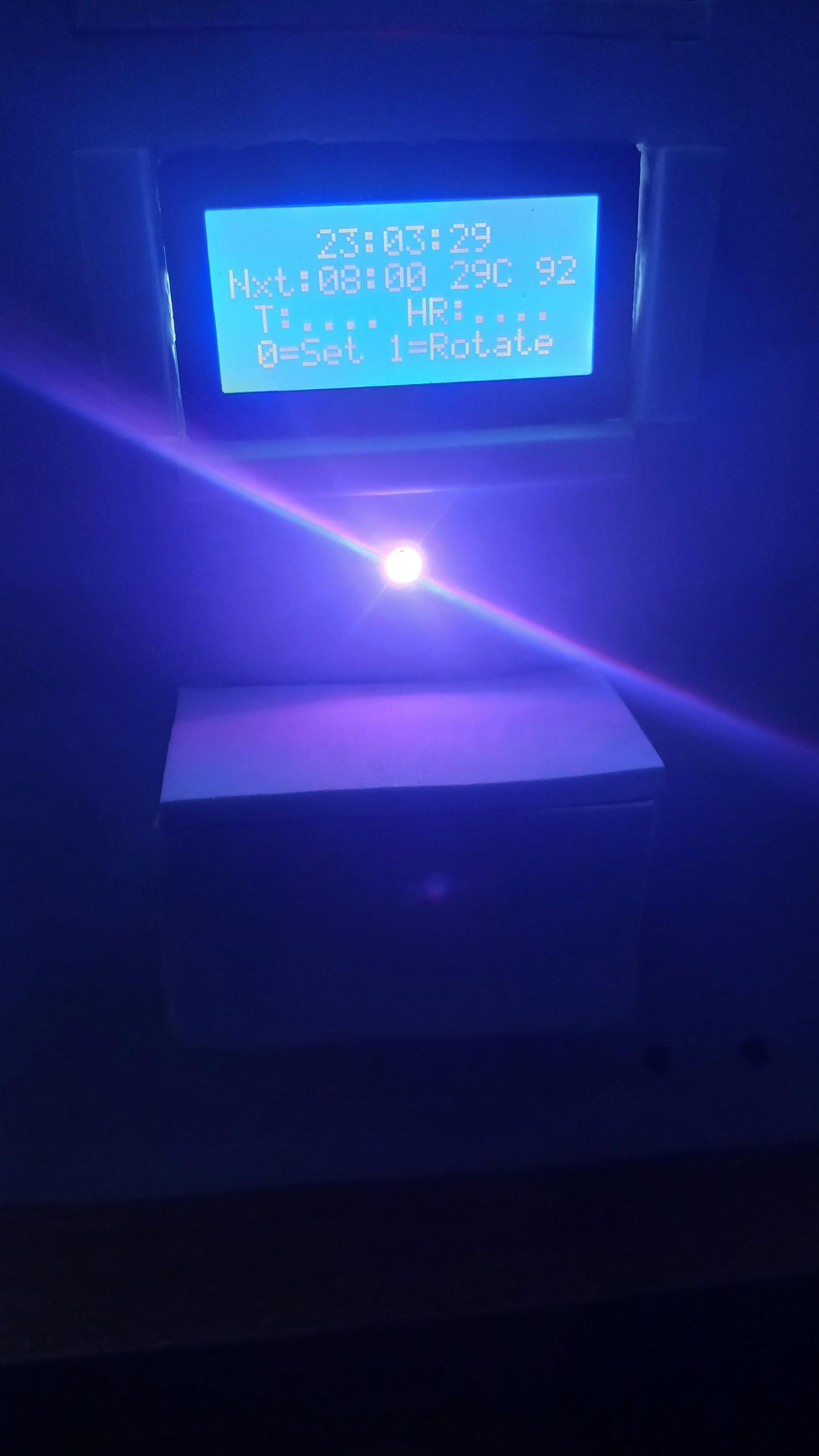
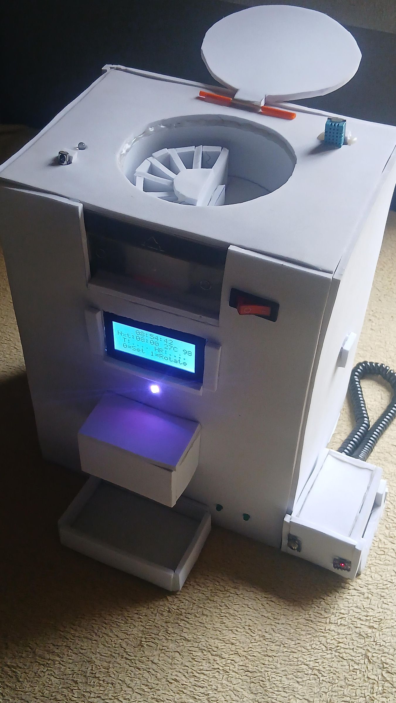
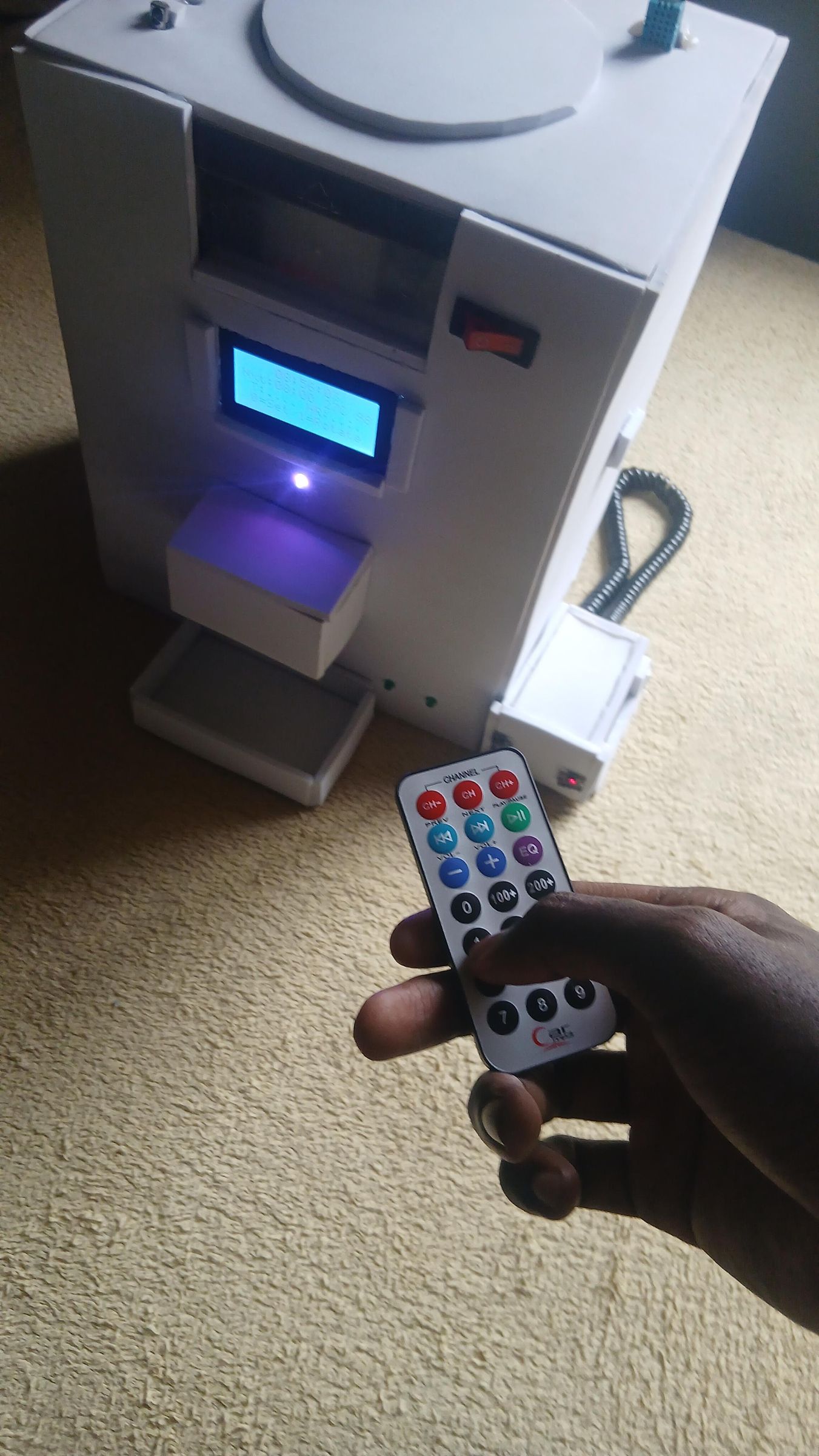
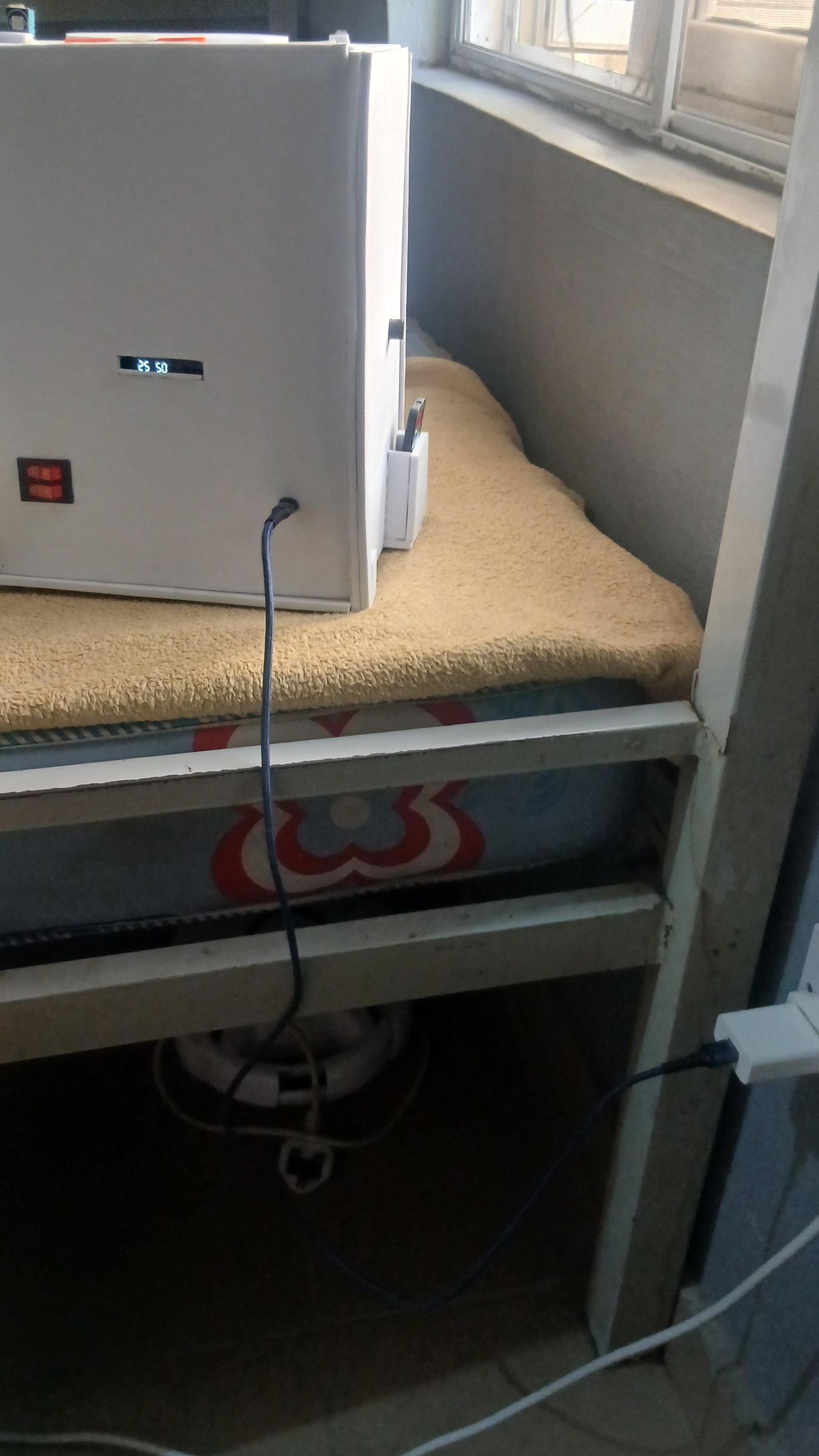
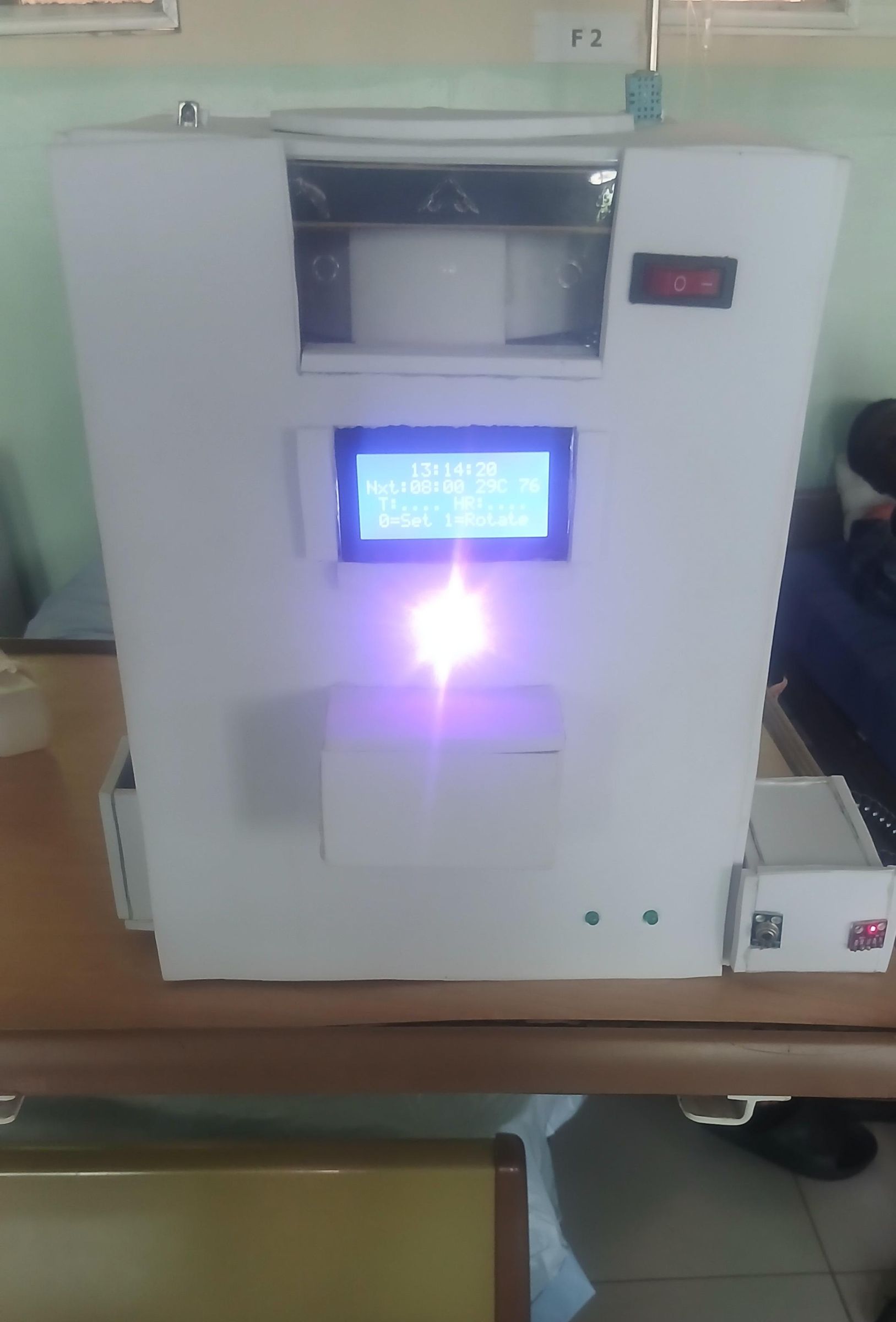
.jpg)
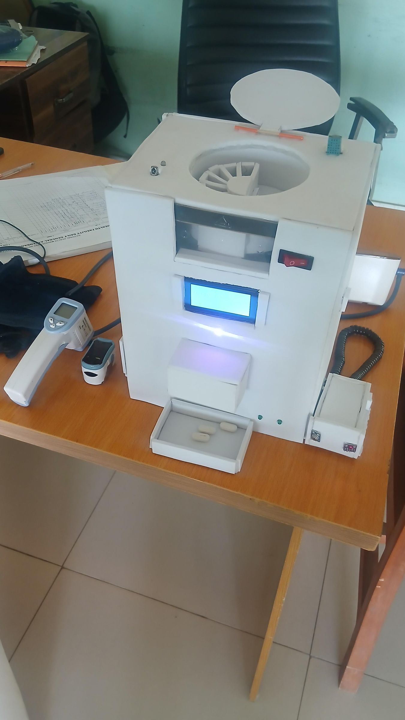
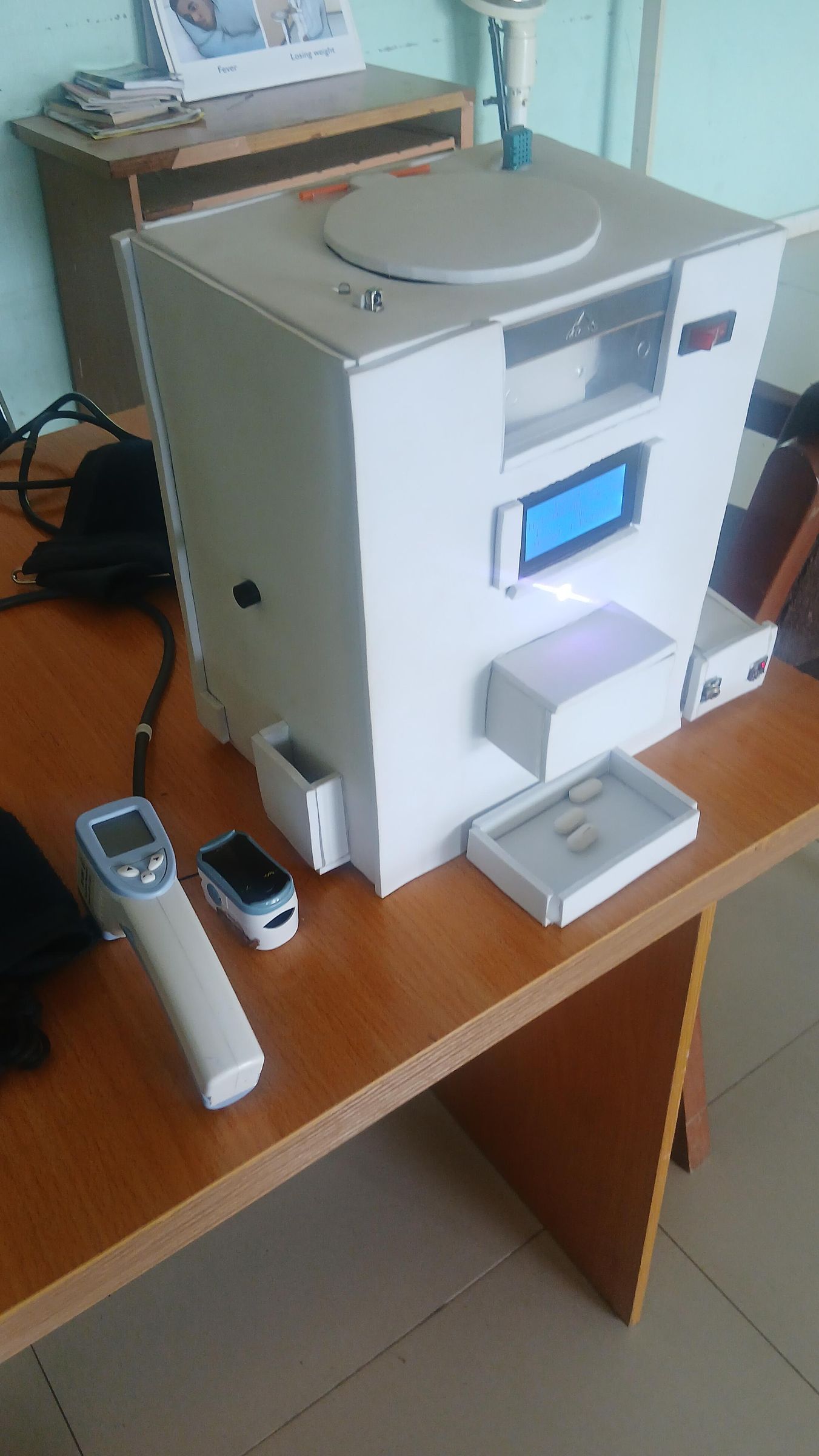
This is the final assembly step where all the internal components are wired up, the enclosure is closed, and the system is tested end-to-end for the first time.
Internal wiring
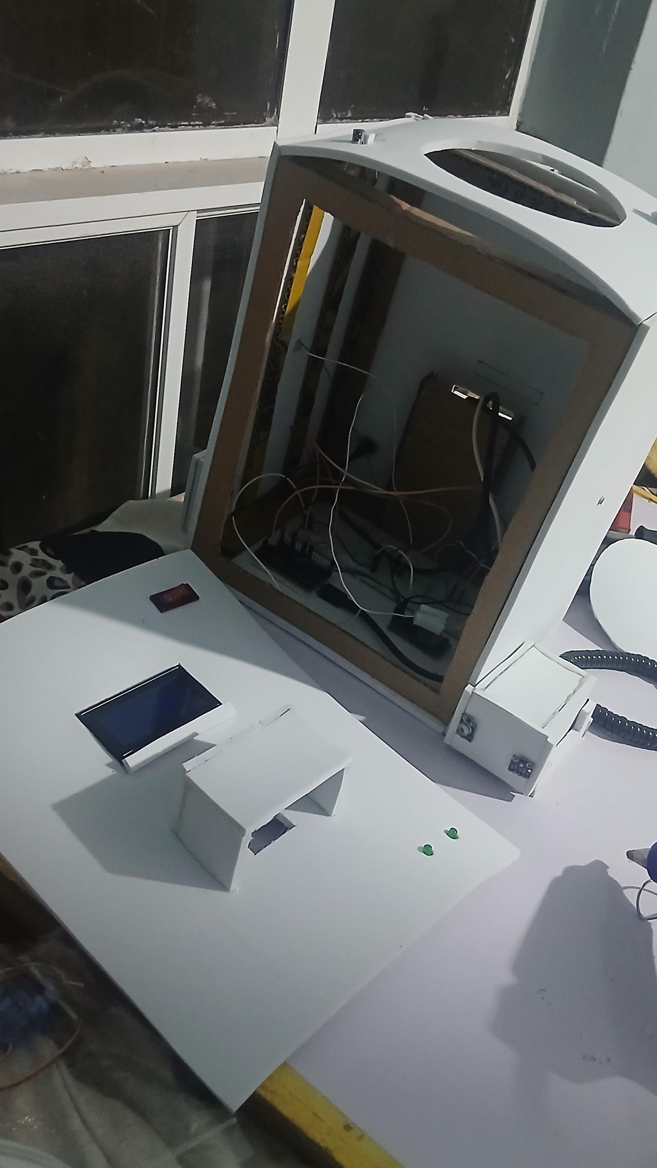
With all panels cut and components mounted, route all component wires down into the enclosure interior. The ESP32 sits on a breadboard at the base of the enclosure, which makes it easy to plug and unplug jumper wires during testing. All sensors share the I2C bus on SDA GPIO 21 and SCL GPIO 22 — this includes the 16×4 LCD (via its I2C backpack), the MAX30102 heart rate and SpO2 sensor, and the MLX90614 contactless body temperature sensor. The DS1302 RTC connects to CLK on GPIO 17, DAT on GPIO 16, and RST on GPIO 27. The IR receiver goes to GPIO 32, the DHT11 to GPIO 4, and the RGB LED to GPIO 23, 5, and 2. The passive buzzer connects to GPIO 25 and the active buzzer to GPIO 18. Green LED 1 (Body Temp indicator) goes to GPIO 26, Green LED 2 (Heart Rate indicator) to GPIO 33, and the white dispensing indicator LED to GPIO 14.
The SG90 servo signal wire runs from the dispenser assembly down through the top panel to GPIO 13. Take care to leave enough slack on the servo wire so the top panel can be lifted during maintenance without pulling connections loose.
Building and fitting the pill dispensing tube
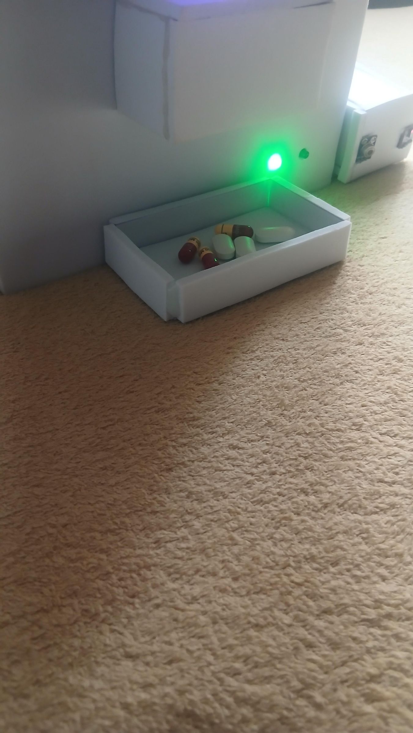
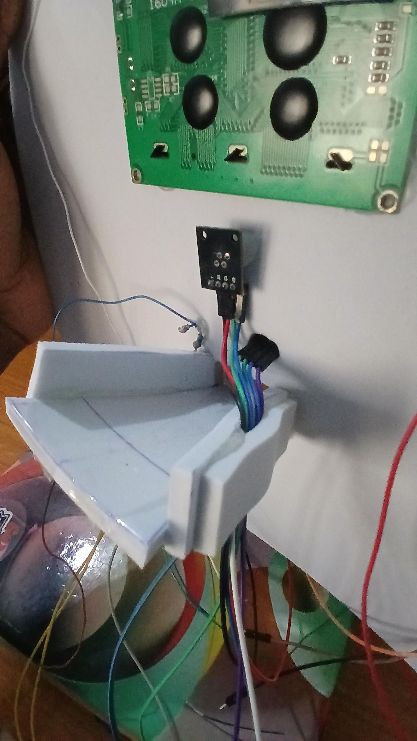
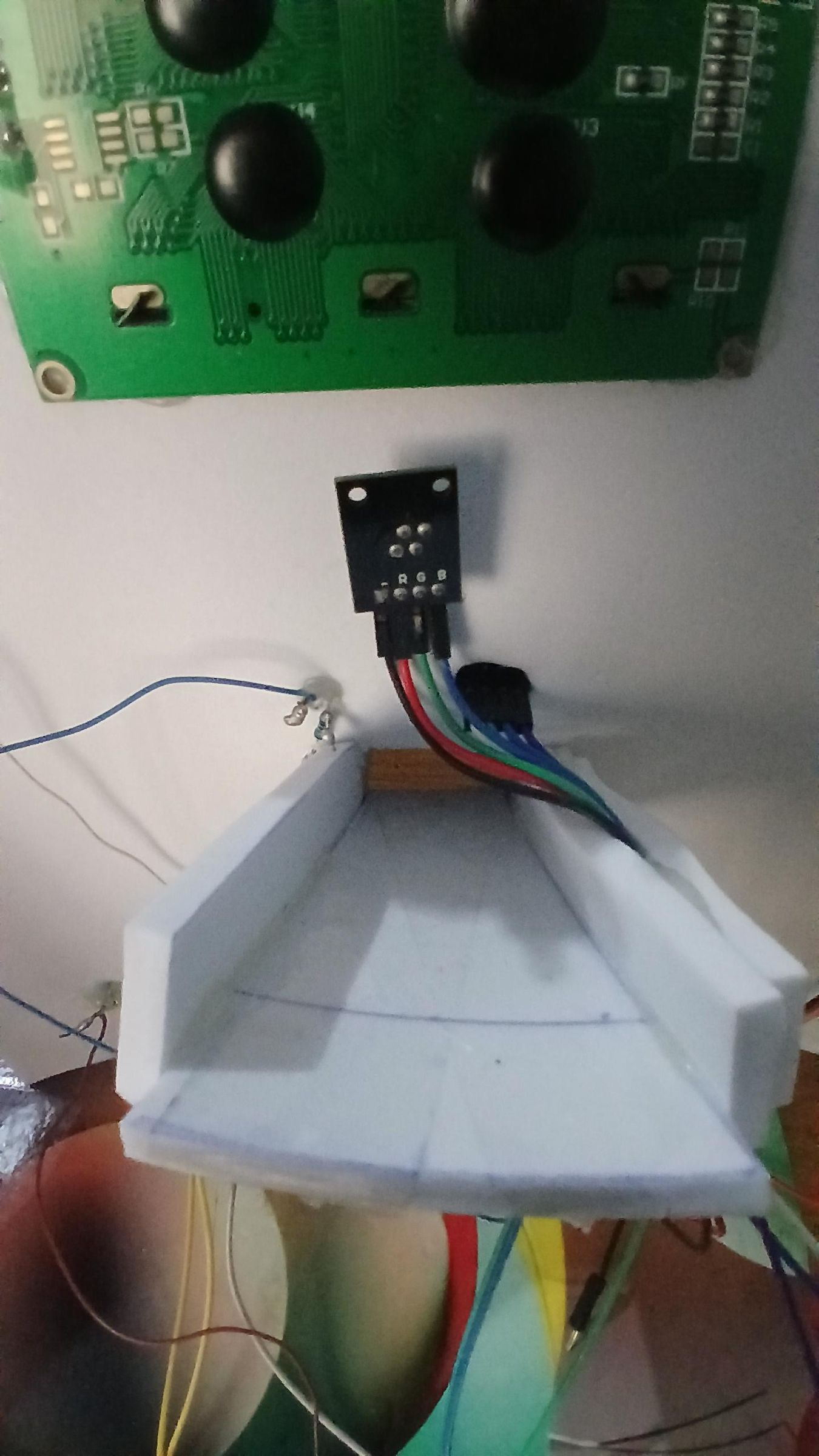
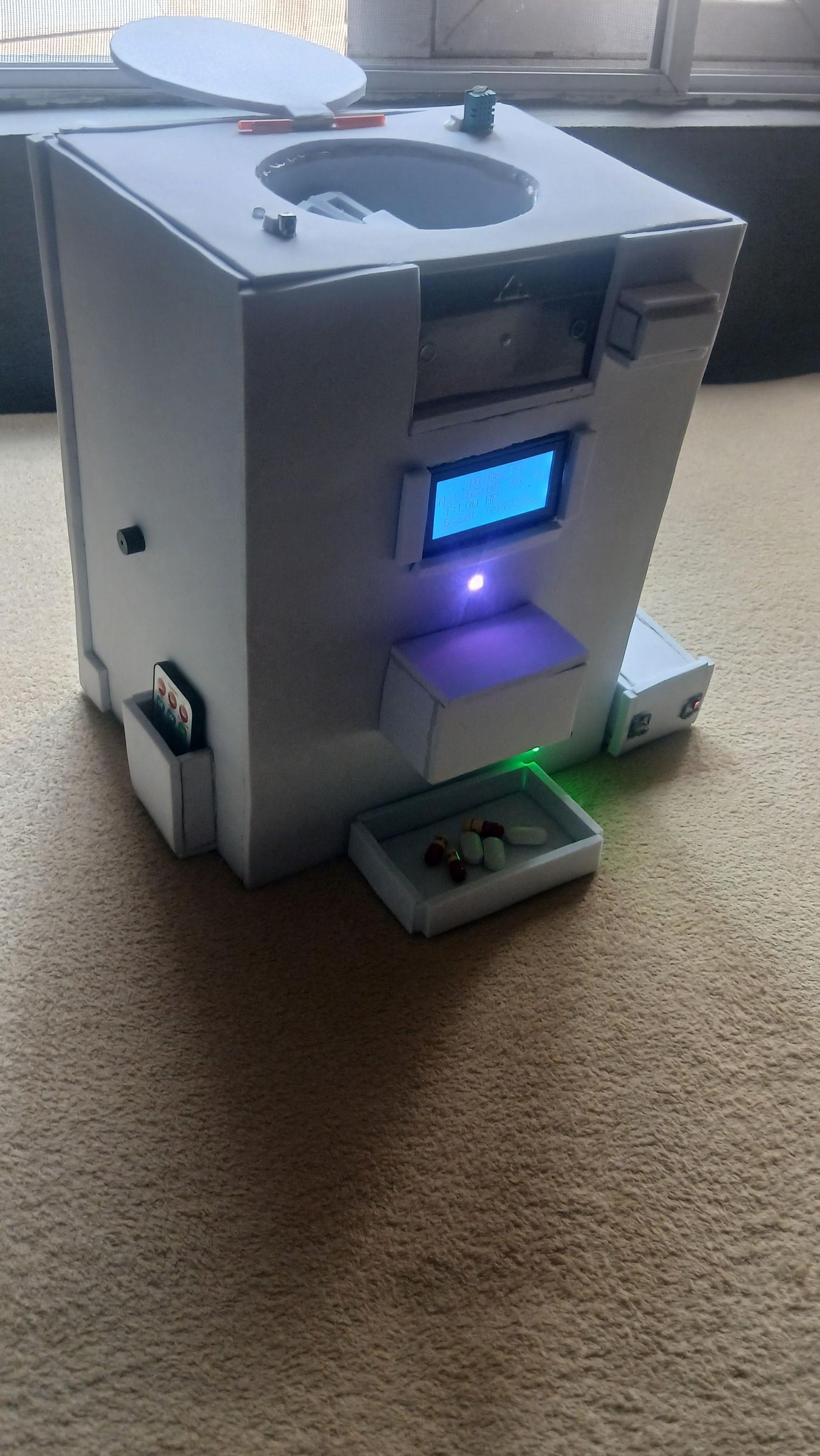
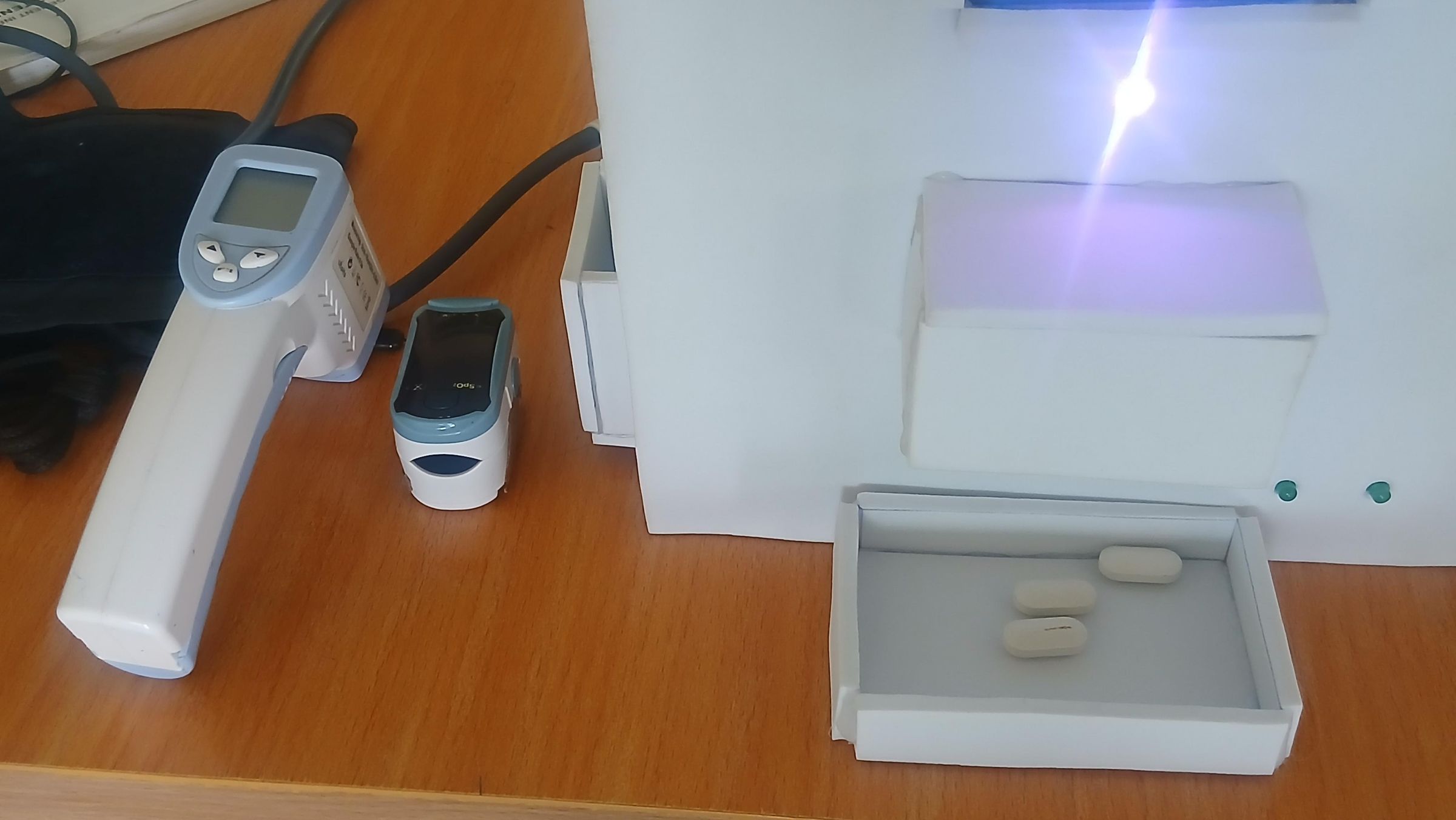
A foamboard chute is constructed and fitted between the circular disk opening on the top panel and the dispense slot on the front panel. This tube guides each pill from the moment it drops out of its compartment on the rotating disk, directing it cleanly downward and forward into the pill collection tray sitting below the front panel slot. Cut and fold the chute from the same foamboard sheet material used throughout the build, sizing it to fit snugly between the underside of the top panel and the dispense opening on the front. Make sure the chute angle is steep enough for pills to slide freely under gravity without jamming, and test with a sample pill before closing the enclosure. The white LED on GPIO 14 mounted just above the chute exit lights up during each dispense motion, making it easy to confirm a pill has been released.
Power bank and battery indicator
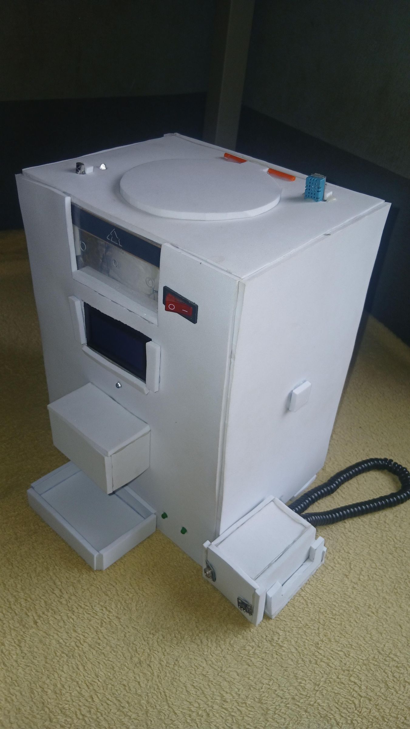
The unit is powered by a built-in power bank mounted in a side enclosure box. A battery level indicator displaying 25, 50, 75, and 100 percent charge is mounted on the rear panel alongside a double rocker switch and the charging port. This allows the device to operate fully cordlessly and gives a clear at-a-glance charge status. The power bank's USB output feeds the ESP32, which in turn powers the sensors and peripherals.
Closing the enclosure
Once all wiring is confirmed and test connections are solid, close the front panel and secure it. The pill collection tray — a shallow foamboard box — sits below the dispense chute on the front panel to catch pills as they are released. The vital signs sensor module (MAX30102 and MLX90614) is housed in a separate small enclosure on the side, connected to the main unit via a cable conduit, keeping the sensing area accessible to the user without opening the main box.
A note on the front panel
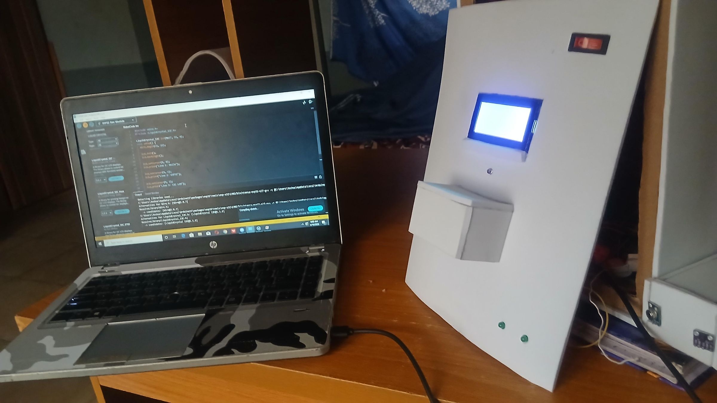
The front panel is not sealed permanently until the ESP32 firmware is fully written, tested, and working to your satisfaction. Keep it accessible during the coding and debugging phase so you can reach the breadboard, swap jumper wires, and re-flash the ESP32 as needed. Only close and secure the front panel once all features — dispensing, vital signs monitoring, alarm scheduling, Bluetooth reporting, and IR remote control — are confirmed working correctly. The complete firmware for this project is provided in the project description. Upload it to your ESP32 using the Arduino IDE before sealing the enclosure.
First power-on and firmware upload
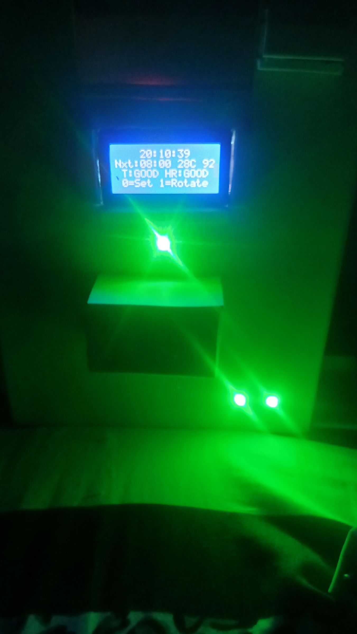
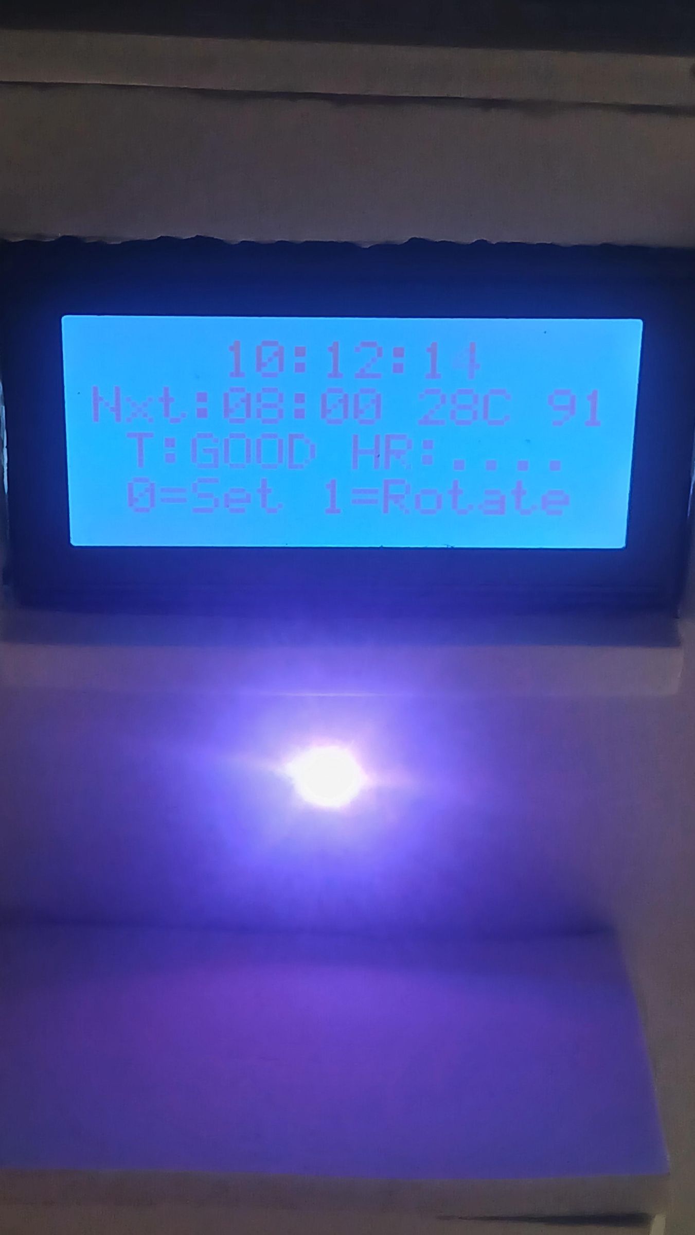
Connect a laptop via USB to the ESP32 and upload the firmware using the Arduino IDE. Once uploaded, disconnect the USB cable and power the unit from the power bank using the rocker switch. The LCD should light up within a few seconds displaying the current time, next alarm slot, room temperature and humidity from the DHT11, and the prompt "0=Set 1=Rotate" indicating the system is ready.
Bluetooth serial monitoring
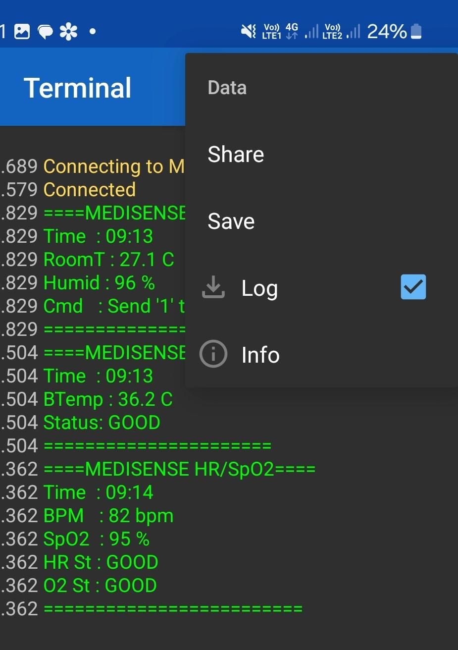
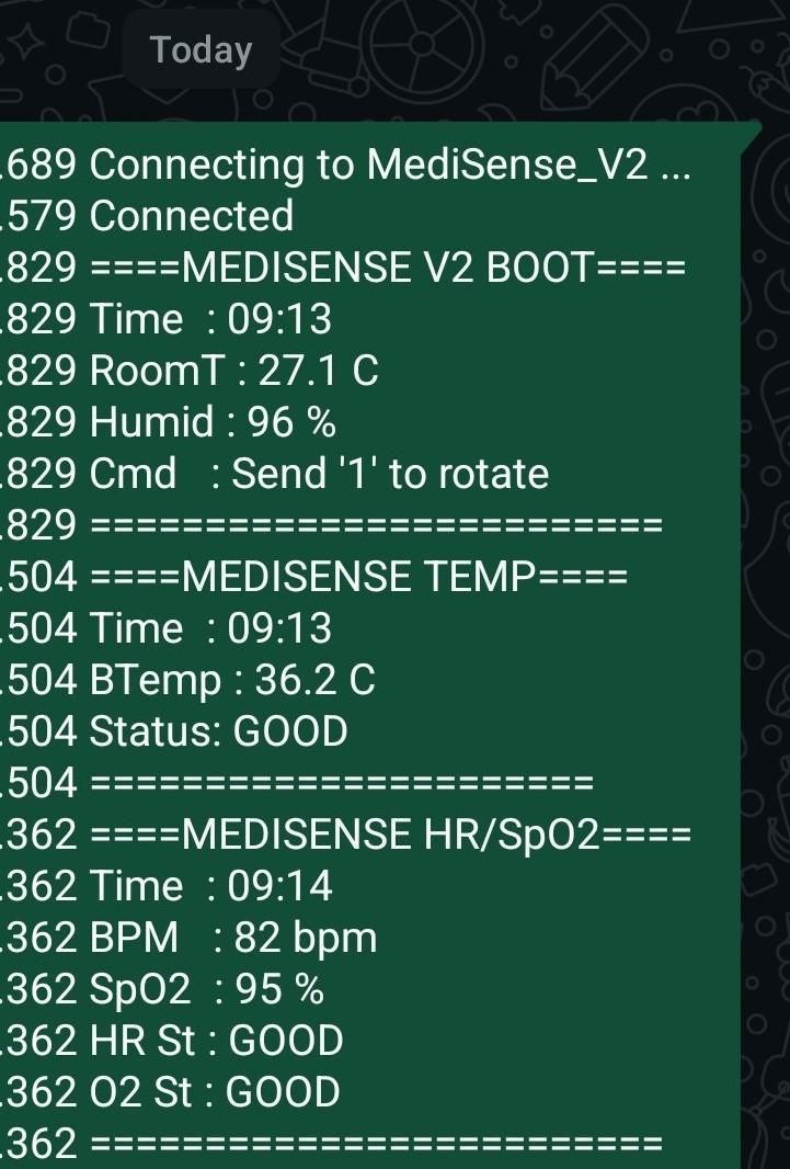
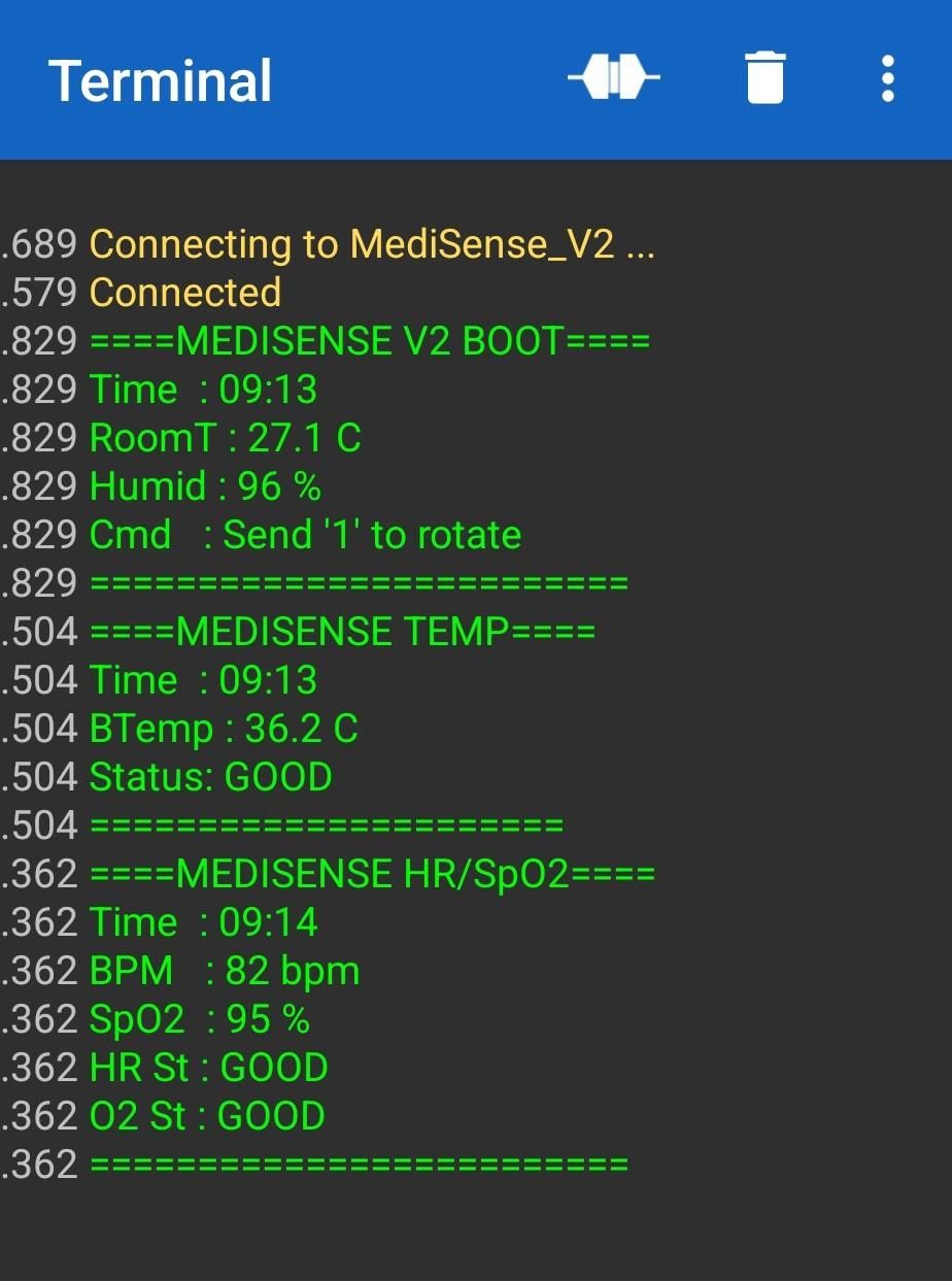
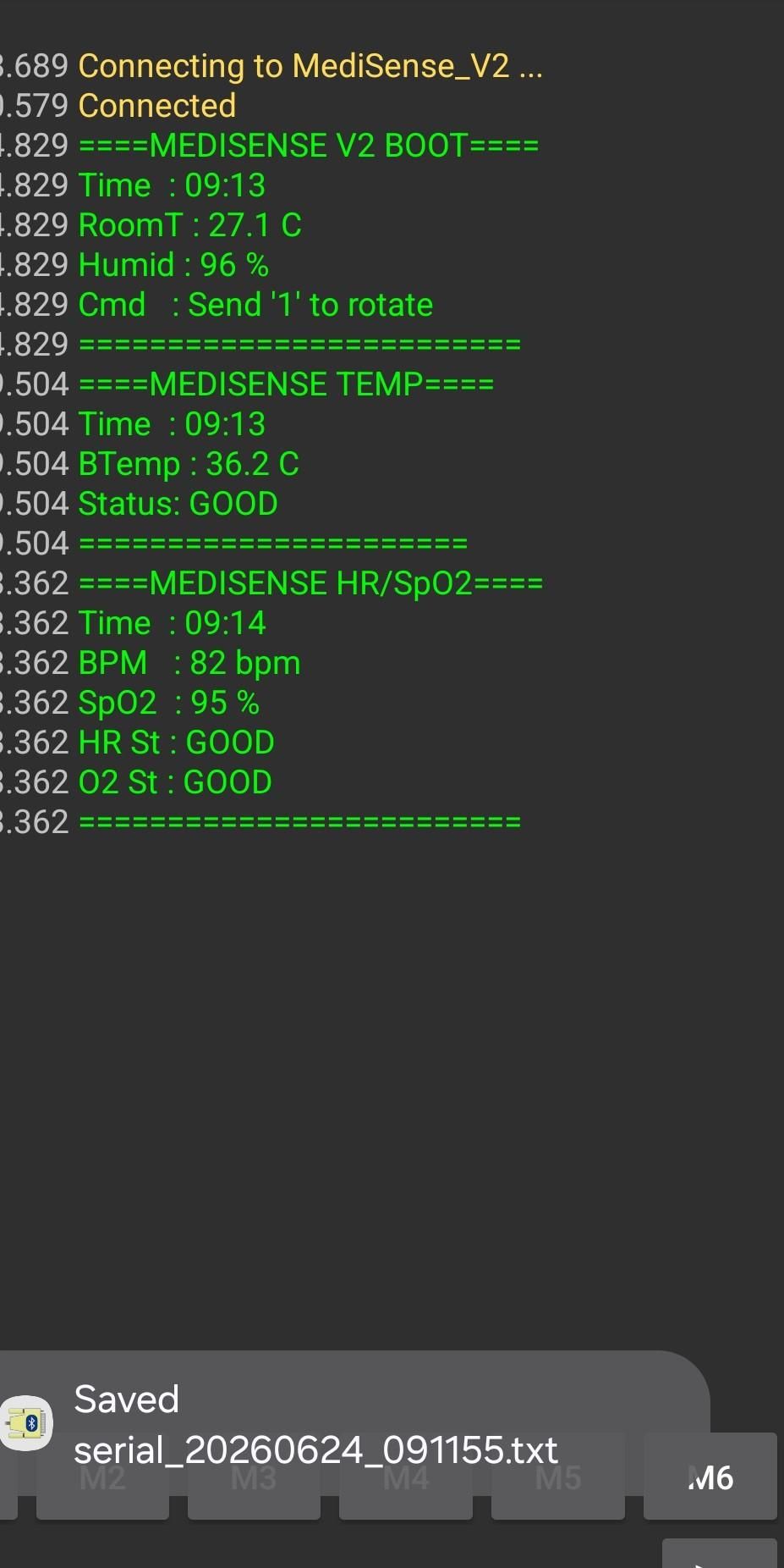
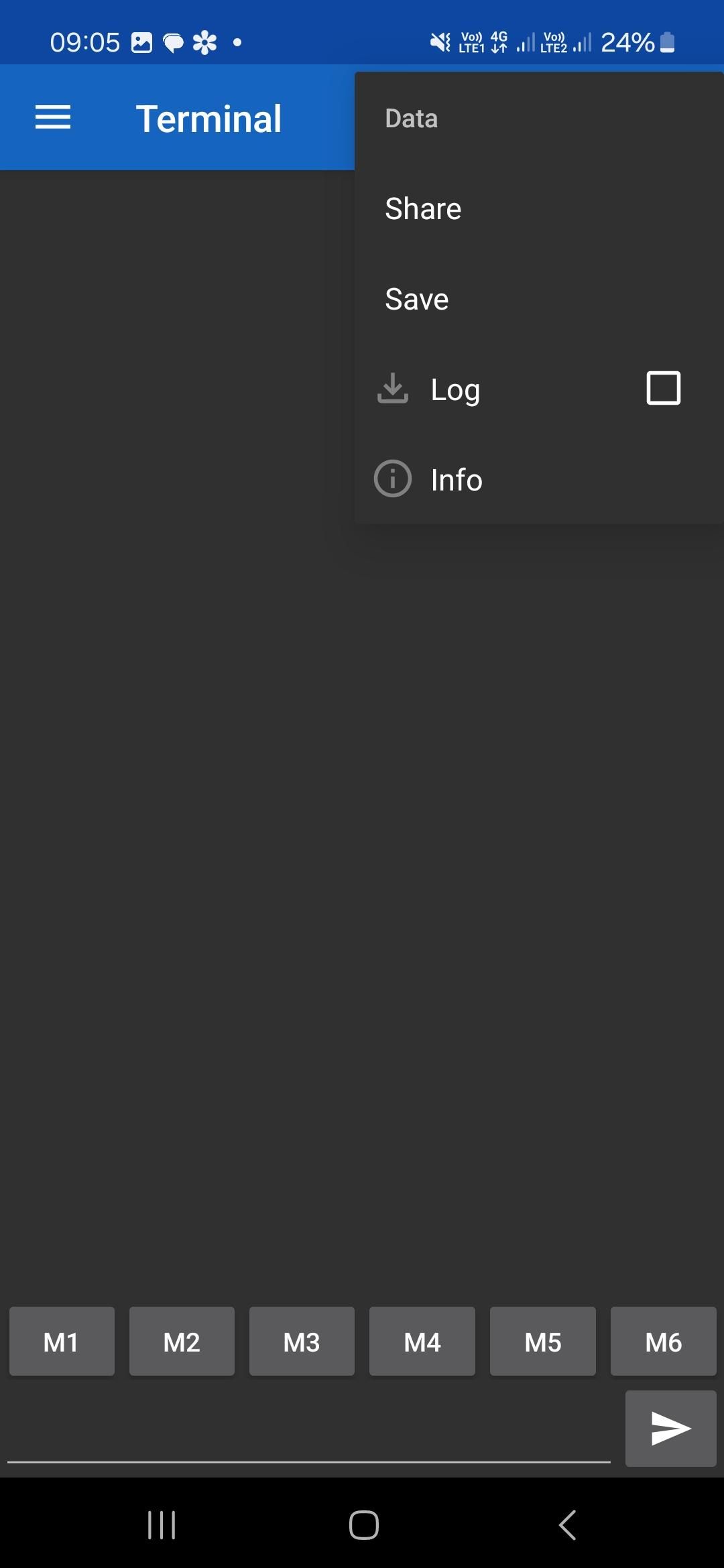
Connect to the device using the Serial Bluetooth Terminal app on Android and pair with "MediSense_V2." On boot, the system broadcasts a status report over Bluetooth showing the current time, room temperature, humidity, and the command prompt to send "1" to rotate the dispenser. After placing a finger on the MAX30102 sensor and waiting the 60-second measurement window, the system reports BPM and SpO2. After holding the MLX90614 sensor close to the wrist or forehead, it reports body temperature and health status. All readings include timestamps and are clearly labelled in the terminal output.
IR remote control
Point the IR remote at the receiver window on the front panel (GPIO 32). Press "1" to trigger a manual dispense step, rotating the disk one slot and releasing a pill into the collection tray below. The white LED on GPIO 14 lights during the dispense motion and turns off when complete. Press "0" to enter alarm time-setting mode via the remote buttons.
Sensor validation and real-world testing
With the device fully assembled and operational, the vital signs sensors were tested for accuracy against clinical-grade equipment. Testing was carried out with permission at my University's health center, where readings from the MediSense V2 were compared against standard medical devices under supervised conditions. The results were accurate and consistent — a sample reading from the Bluetooth terminal showed a body temperature of 36.2°C (status: GOOD), heart rate of 82 BPM (status: GOOD), and SpO2 of 95% (status: GOOD), all within clinically acceptable ranges. The health center test went really well and confirmed the device works as a functional prototype for automated pill dispensing and basic vital signs monitoring.
And that's it — you're done! No more forgotten medications, no more guessing how your body is doing. Whether you're keeping tabs on your own health, checking in on a loved one, or keeping an eye on a patient or elderly grandparent, MediSense V2 has got it covered. It reminds, it dispenses, it monitors — all in one neat little box you built yourself. Pretty cool, right? Now go load those compartments up and let it do its job!