MicroPython Scale With HX711 - Part 1
by AZDelivery in Circuits > Arduino
681 Views, 0 Favorites, 0 Comments
MicroPython Scale With HX711 - Part 1
.png)
This project will show you how to build a highly precise digital scale using a load cell.
Supplies
1x ESP8266 or ESP32 Board
D1 Mini Nodemcu with ESP8266-12F WLAN module or
D1 Mini V3 Nodemcu with ESP8266-12F or
Nodemcu Lua Amica Module V2 ESP8266 ESP-12F WiFi or
Nodemcu Lua Lolin V3 Module ESP8266 ESP-12F WIFI or
ESP32 Dev Kit C V4 unplacerated or
ESP32 NODEMCU Module WiFi Development Board with CP2102 or
ESP32 Lolin Lolin32 WiFi Bluetooth Dev Kit
1x Display
0.91 inch OLED I2C Display 128 x 32 pixels
1x Weighing cell 1kg
1x HX711 AD converter for weighing cells
1x
MB-102 Breadboard Pug with 830 contacts
various wires
Jumper Wire cable 3 x 40 pcs. 20 cm M2M / F2M / F2F each possibly too
65stk. Jumper wire cable plug -in bridges for Breadboard
optional
The software
For flashing and the programming of the ESP32:
Thonny or
Used firmware for the ESP32:
Used firmware for the ESP8266:
The micropython programs for the project:
SSD1306.PY Hardware driver for the OLED display
oled.py API for the OLED display
geometer_30.py Large character set for the digit display
hx711.py API for the AX711
scale.py The operating program
zeichensatz.rar Working environment for creating your own symbols
Install Thonny
To install Thonny you will find one here Detailed instructions (English version). There is also a description of how that Micropython firmware (As of 18.06.2022) on the ESP chip burned becomes.
Micropython is an interpreter language. The main difference to the Arduino IDE, where you always flash entire programs, is that you only have to flash the Micropython firmware once on the ESP32 so that the controller understands micropython instructions. You can use Thonny, µpycraft or ESPTOOL.PY. For Thonny I have the process here described.
As soon as the firmware has flashed, you can easily talk to your controller in a dialogue, test individual commands and see the answer immediately without having to compile and transmit an entire program beforehand. That is exactly what bothers me on the Arduino IDE. You simply save an enormous time if you can check simple tests of the syntax and hardware to trying out and refining functions and entire program parts via the command line before knitting a program from it. For this purpose, I always like to create small test programs. As a kind of macro, they summarize recurring commands. Whole applications then develop from such program fragments.
Autostart
If the program is to start autonomously By switching on the controller, copy the program text into a newly created blank tile. Save this file under boot.py in WorkSpace and upload it to the ESP chip. The program starts automatically the next time the reset or switching on.
Test programs
Programs from the current editor window in the Thonny-IDE are started manually via the F5 button. This can be done faster than the mouse click on the start button, or via the menu run. Only the modules used in the program must be in the flash of the ESP32.
In between, Arduino id again?
Should you later use the controller together with the Arduino IDE, just flash the program in the usual way. However, the ESP32/ESP8266 then forgot that it has ever spoken Micropython. Conversely, any espressif chip that contains a compiled program from the Arduino IDE or AT-Firmware or Lua or ... can be easily provided with the micropython firmware. The process is always like here described.
Build the Circuit
Here are the circuit diagrams for the project, it works free of choice for ESP32 and ESP8266. The GPIOs for connecting the HX711 are chosen so that you do not hinder the start of the ESP8266 and have the same names for both controller types. Only the connections for the I2C bus are different, but are automatically assigned By the program.
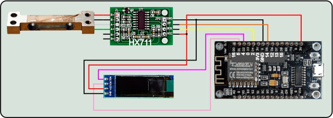
Figure 6: HX711 scale on the ESP8266

Figure 7: HX711 scale on the ESP32
Micropython Module for the HX711
Like most sensor assemblies, the HX711 module also needs operating software. Unfortunately, the HX711 is not I2C-capable. The data transmission also takes place in a serial manner via the lines dot and dpclk. 24 bit plus 1 to 3 bit are always transferred for the selection of channel A or B and the setting of the reinforcement. The MSbit (Most Significant bit = high -quality bit) is the first bit the HX711.
For programming the module hx711.py do I have this The manufacturer's data sheet used.
The exception class deals with the case that the HX711 is not accessible. This is followed By the declaration of the HX711 class, that of Devicenotready inherits. With the throwing of the exception, an instance is generated and the constructor ensures the output of the error message.
We start with a few constants. The calibration factor is determined By some weighings with various known massage pieces and a calculation tool, for example Libre Office. I will come later.
The constructor takes the two pin objects dot and pdsk, as well as the optional channel in ch. Dout is switched as an entrance, because it should receive the data from the outcome of the HX711. The ESP specifies the pace via the DPSCK management. We declare the attributes channel, tar and cal, then we wait for the Ready signal of the HX711. If it doesn't come, then throws WAITREADY() one Devicenotready-Exception. If it worked, then we get the channel and gain setting and issue a message in the terminal. The Dictionary Channelandgain convert the channel number into plain text.
The Closure Time-out() realizes a software timer who does not block the program as it is sleep() & Co.. The returned function compare() If a identifier is assigned to be asked about whether the time passed on has already expired in milliseconds (True) or not (false).
The method ISDEVICEREADY() returns True when the data line is on GND potential. According to the data sheet, this is the condition if the HX711 is ready to send data. With the first positive flank on the clock line, the HX711 provides the MSbit on the DOUT line.

Figure 8: Logic 2-scan
With each additional pulse, the bits are pushed out in turn. In the meantime, the ESP must read and process the condition of the line. The ESP sets the pace through the clock. The pulse sequence is 125µs, which corresponds to a clock at approx. 8 kHz.
I have the pulse consequences with a logic analyzer and the software Logic 2 recorded. Whenever there are problems with data transmission, I like to use the DSO (digital memory oscilloscope), or a smaller tool that is cheaper for worlds Logic analyzer (La) with 8 channels. The thing is connected to the USB bus and shows using the Free softwarewhat is going on on the bus pipes. Where the shape of impulses does not matter, but only on its time sequence, a LA is worth gold. And while the DSO only provides snapshots of the curve, you can feel the LA over a long time and then zoom yourself into the interesting places. You can find a description of the device in the blog post "Logic Analyzer Part 1: Make I2C signals visible"By Bernd Albrecht. There it is also described how to scan the I2C bus.
After reading the 24 data bits, one to three more pulses are used pdsk issued, the tax bits. You have the following meaning:
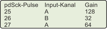
Figure 9: Meaning of the control pulses
The name is program, WAITREADY() waiting for a true of ISDEVICEREADY(), but previously put the timer on the value in Readydydelay, that's three seconds. If Dout does not go to low during this time, one will be one Devicenotready-Sexception thrown. This brings off the calling program if it does not intercept the exception.
The HX711 sends the data as a two-complement values. Conpricerult () actually recognizes negative values in the set MSbit, the bit 23. If it is set, the level 2 is the level 2 of the24 Subtracted to really get a negative number.
0xc17ac3 = 12679875 has a set MSbit
12679875 - 0x1000000 = -4097341
clock() just generates a positive pulse of 12.4µs on the PDSCK line.
You overlook channel() No argument, then the function delivers the current channel and gain values. The Dictionary Hx711.channelandgain Take over the translation into plain text.
Once a channel number has been handed over, we check for the correct area, check whether the HX711 is ready and then push the corresponding number of pulses onto the PDSCK line, 24 plus the tax bits.
The raw values that the HX711 delivers are By traw() received. Becomes True Or not handed over an argument at all, then the return value is pink, i.e. an integer with a sign. With false the value Bloody returned, as it corresponds to the bit sequence, raw.
We are waiting for the sending of the HX711 and set the receiving buffer to 0.
In the for loop we send 23 pulses on PDSCK. With each run, we are in the place of the LSBIT (LEAST Significant bit = low -quality bit) the condition on the data line and then push the bits By one position to the left. The first received bit moves to position 23, the MSbit. After another clock pulse, the HX711 pushes the LSbit onto the data line, which we only on the LSbit of raw or have to. In addition to competition, the tax bits for the next measurement must then be clocked.
To smooth the noise of the values, we not only use a single measured value, but the mean from several measurements. That gets the method mean(), which we hand over the number of individual measurements.
The unpolluted scale naturally also delivers an ADC value, the Tara. We always call the method when booting the weighing program in order to be able to set the display to 0. The Tara value is in the attribute self.are saved so that the method Dimensions() has available, n is again the number of individual measurements.
The method Dimensions() pulls the Tara off the measured value and then calculates the true measured value in grams By division with the calibration factor. I will show how it is determined later.
During the calibration, it is an advantage if you can handle the calibration factor manually without having to newly upload the HX711.PY module to the ESP every time. The current value will be returned without an argument.
wake up() and tosleep() tickle the HX711 from sleep mode, or put it in it. The signal sequence on the lines is specified By the data sheet of the HX711.
Big Character Set for the OLED Display
Large digits make it easier to read the measurement. Instead of the usual eight pixels, we use 30 as a sign. The file geometer_30.py Contains the relevant information.
And so you make your own character set from the TTF supply from Windows.
Download the archive zeichensatz.rar Down and unpack the content into any directory. To save tipping, I recommend a list with a short name in the root path of the hard drive or a stick. With me it is F: \ fonts.
Open a PowerShell window in this directory from the Explorer By making a right click on the directory with a push button pressed. Then left click on Open the PowerShell window here.

Figure 10: Open PowerShell window
Enter the following line at the prompt and press Enter:
. \ Makecharset.bat Britannic 30 "" 0123456789,-+KG "" "F: \ fonts \ sources \"

Figure 11: The character set is ready
There is now a file in the directory britannic_30.py With the pixel data of the new character set. Only the characters were implemented in "" "0123456789,-+KG" ", that saves storage space. You can get other sign rates from the fonts-List of Windows in the directory sources Copy and convert as specified above. Please note that the file name is specified without the addition .TTTF.
Operating Software of the Library
The program scale.py accesses four external modules that have to be uploaded to the flash of the ESP before starting, hx711.py, oled.py, SSD1306.PY and geometer_30.py.
About the variable sys.platform an ESP can determine its himself. Then the GPIO pins are declared for the I2C bus.
We instantiate a display object, delete the display and declare the PIN objects for the connection to the HX711, also button, the instance for the Tara key.
The function Putnumber() positions the pixel pattern of the character with the number n (based on the extract generated above, not Ascii). The position of the top left corner of the pattern is in XPOS, YPOS.
A look at the file geometer_30.py explains the procedure. In the string chars the characters are listed. The index in the string is the drawing number. The "-" sign is therefore number 11, the "0" is number 0. In the list number this number identifies the Tupel With the width information and the pixel matrix. This is now scattered By line column for columns and the pixel is set when a 1 has been found. That happens hidden. Only if show the value True Has, the entire buffer is sent to the Display. The return value is the next free drawing position.

Figure 12: Matrix for the sign 0
The drawing position is set to 0, as a start information I give a number of "-" signs. Then the ESP tries to contact the HX711. If this succeeds, we wake it up, channel A with Gain 128 and see the TARAWALT that in the attribute self.are lands.
If the connection does not work, we get a message in the terminal and a series of zeros in the display.
160MHz is for the ESP8266 Topspeed, the ESP32 also packs 240 MHz.
Then it goes into the main loop. We see if the Tara key is pressed, confirm this with a series of commas on the display and get a new Tara value. This feature is useful because the weighing cell is subject to a temperature drift and the zero point can be readjusted at any time.
The format string for the output is fed with the measured value. Disconnect the display, delete the drawing position to 0, decimal point with a comma and write the characters in the buffer up to the penultimate.
With the output of the last character, the buffer content is sent to the display. The next round starts after half a second break.
You can download here.
Calibrate the Scale

Figure 13: Mass pieces for calibration of the scale
You need a few mass pieces and, if necessary, a kitchen or letter scale if the mass pieces are not calibrated. In this case, you can make a lay of fat nuts or screws or the like. Of course, the masses must be determined with a different scale before use.

Figure 14: Calibrate on the ESP8266
Start the program now scale.py In Thonny and break in the main loop Ctrl+C away. The HX711 object is under HX instantiated and accessible from the terminal console. We start with the following commands.
We subtract the Tara value from the average of 25 individual measurements. The results should be between -50…+50 if the scales are not loaded.
Now we lay the mass pieces one after the other and in groups, so that it is increasingly stressed. Every time we start the last command again and write down the mass in Grams and the value displayed in the terminal.
The Table Let us enter in Libre Office Calc or another program and display the measurement curve together with the determination (correlation coefficient) and the formula.

Figure 14: Calibration curve
The correlation coefficient R2 Is in fact 1, that speaks for the precision of our measurement. We can neglect the axis section of -43, ... with an order of 100,000. The slope factor 1104 of the straight line is our sought -after calibration factor. Now share this value to the object HX with.
If you are now the method Dimensions() Call up, a value of 0.0 ... should be displayed.
Wear the calibration factor in the file hx711.py one, upload them to the ESP and start the program scale.py new.
If the mass is displayed when the masses are put on, they have won and can pound on the shoulder.
If the displayed value is slightly next to the expected weight, you can still file a little on the calibration factor value. If you enlarge it, the mass value will fall and vice versa.
In the second part I show you how I exchanged the OLED for a large LED display. Until then.