Microrack Modular Synth: MIDI to CV Using Cytron Maker Nano 2040 and Adafruit MCP4728 DAC With I2C Isolation
by kevinjwalters in Circuits > Audio
166 Views, 1 Favorites, 0 Comments
Microrack Modular Synth: MIDI to CV Using Cytron Maker Nano 2040 and Adafruit MCP4728 DAC With I2C Isolation
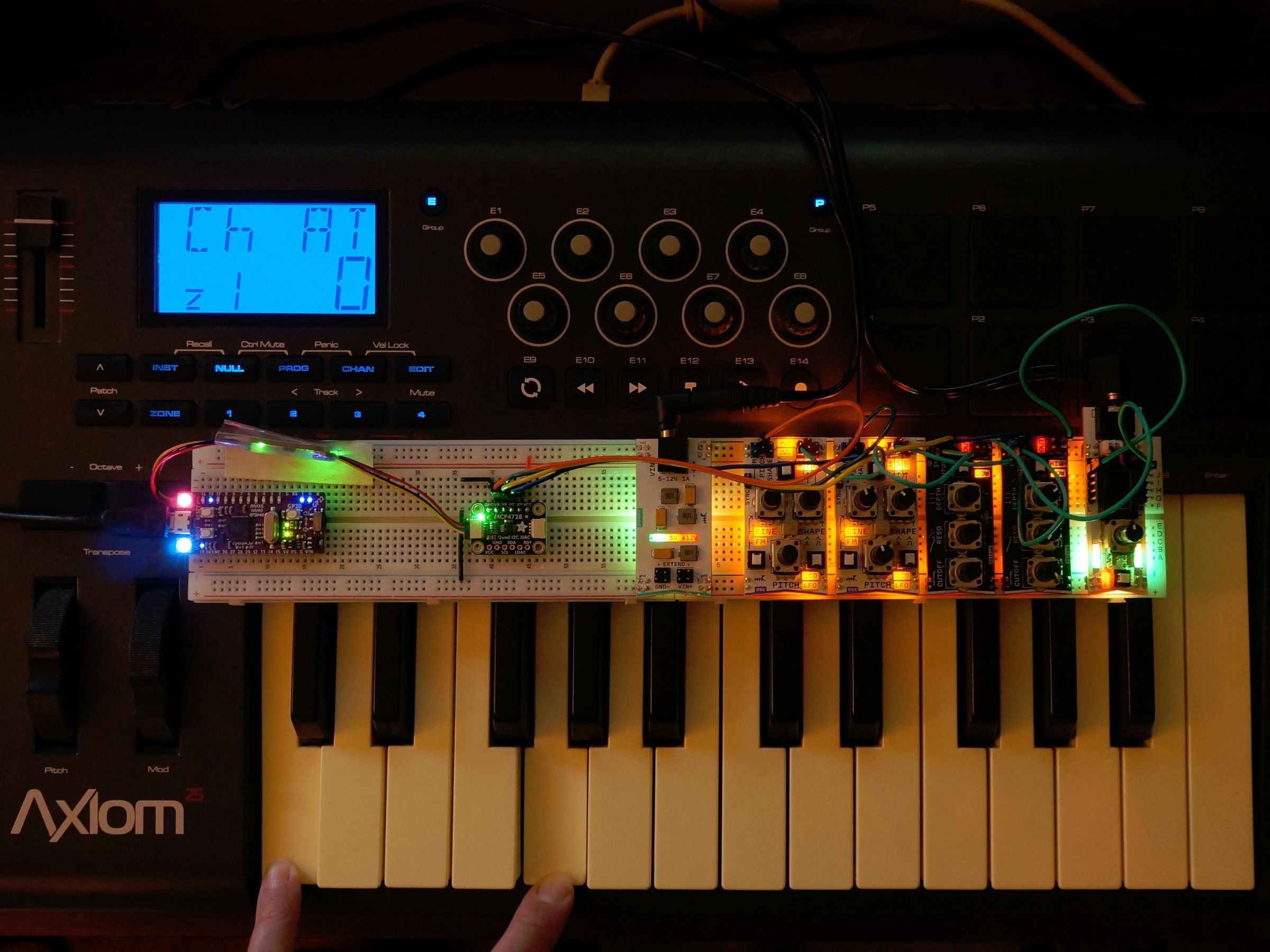
Microrack is a series of modular analogue synthesizer modules in a very small format designed to plug into a standard 830 point breadboard. The modules use Eurorack-style control voltages with connectivity provided by single conductor jumper wires and a common ground.
For those willing to abandon analogue purity this article shows how to use a third-party microcontroller board with Microrack to present a Musical Instrument Digital Interface (MIDI) device over USB. Microrack sell a midi->cv module which offers DIN MIDI (TRS type A) but not over USB MIDI. If you don't own the midi->cv module or want MIDI over USB and have a drawer full of microcontroller components this is an alternative way to support MIDI and explore the Microrack world.
A fairly simple CircuitPython program reads MIDI messages from the USB port and using an optional galvanically isolated digital-to-analogue converter (DAC) generates control voltages for pitch and gate. There's also the option of outputting note velocity or using synthio-generated envelopes The use of CircuitPython makes the software relatively easy to modify and enhance.
A Cytron Maker Nano 2040 was used together with an Adafruit ISO1540 Bidirectional I2C Isolator and an Adafruit MCP4728 Quad DAC. All of these boards feature STEMMA QT connectors which simplify the inter-board connections.
The demonstration features a straightforward duophonic synthesizer patch making good use of the four channels on the DAC.
This setup could also be adapted for use with other systems like littleBits or Eurorack.
This project involves some very simple soldering to attach one row of header pins to the DAC board to allow it to be inserted into a breadboard to facilitate connecting its outputs to modules.
Supplies
- Microrack (check the shipping time and read about delays)
- Synth Starter Kit: Microrack
- 1x oscillator module: Microrack
- 1x filter module: Microrack
- Cytron Maker Nano 2040**: DigiKey | PiHut
- Male-male short Qwicc/STEMMA QT cable: DigiKey | PiHut
- Adafruit MCP4728*** Quad DAC with EEPROM: DigiKey | PiHut
- Galvanic isolation (optional but useful to increase control voltage range)
- Adafruit ISO1540 Bidirectional I2C Isolator (optional): DigiKey | PiHut
- Male-male short STEMMA QT cable.
- Some solid-core AWG22 wire in red and black (and wire strippers) or 2x short male-male jumper wires for power, one red and one black
- 4x male-female jumper wires for connecting DAC outputs to modules.
- Solder, soldering iron to attach one row of header pins to DAC board.
** Or any CircuitPython-compatible board ideally with Qwicc/STEMMA QT connector, e.g. a Pimoroni Tiny 2350.
*** Or any other i2c controlled DAC with at least 2 channels, CircuitPython library support, an internal voltage reference (>4.0V) and ideally a Qwicc/STEMMA QT connector.
Selecting a Microcontroller Board
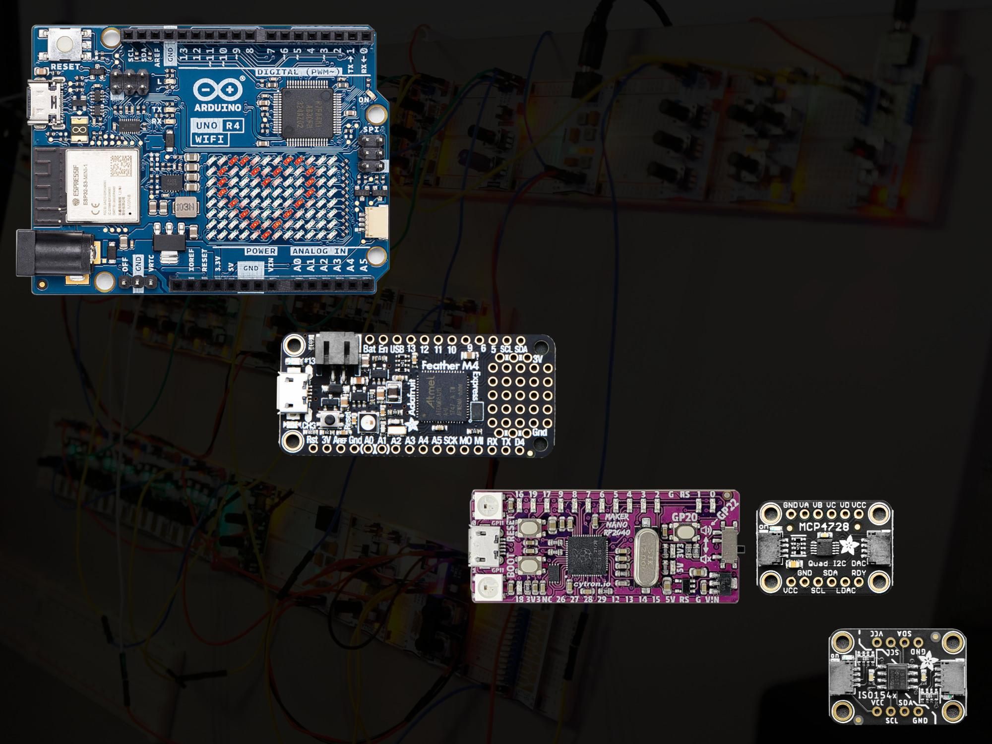
The ideal microcontroller board would have:
- 5V outputs;
- one or more DAC outputs;
- USB MIDI capability and a good library for this;
- a convenient, common connector to simplify wiring.
Plan A
The modern Arduino UNO R4 WiFi initially appears attractive based on its DAC and Qwiic connector. The R4 WiFi and R4 Minima support serial MIDI (over DIN) but unfortunately these
- do not currently support USB MIDI,
- do not output 5.0V when they are powered by USB due to the voltage drop from a schottky protection diode and
- do not run CircuitPython.
Plan B
An alternative is to use a 3.3V microcontroller board. The ATSAMD21 and ATSAMD51 microcontroller-based boards feature one 10 bit and two 12 bit DACs, respectively. These could be used but the output is limited to the range of 0.0V to 3.3V. This covers a reasonable 40 keys for a pitch control voltage (using 1V/oct) but the problem is the gate output is limited to 3.3V too and this might not work well with all of the Microrack modules which are largely intended for 5.0V levels.
Plan C
A 3.3V microcontroller board with an external DAC board which can operate from 5.0V seems like a good solution.
The issue here is the microcontroller needs to communicate with the DAC board and this will typically be done over an i2c bus leading to the issue of signal voltage compatibility. If the DAC board is powered at 5.0V then the i2c bus will typically operate at 5.0V and this will be incompatible with most 3.3V microcontrollers.
Hurdle
A further issue is Microrack's +5V rail which is a tempting way to power a DAC board. This does not run at exactly 5.0V. Some measurements are shown with an eight module patch in Step 3: Powering the LogicBoard in Microrack Modular Synth: Ring Modulation With LogicBoard From MH-EDU-Electronics - these range from 4.86V right down to 3.61V. An independent voltage reference or supply voltage for the DAC is clearly useful to allow the DAC to output a predictable voltage. An incorrect control voltage for pitch will either force the oscillator to be retuned to match the DAC output or make tuning impossible - accurate voltage output is essential for pitch.
Plan D
Bidirectional level conversion for SDA and SCL lines is one way to allow an i2c bus to safely connect a 3.3V microcontroller to a DAC running at 5.0V. Another option is for i2c bus to be fully isolated with a specialist chip. Texas Instruments make a range of these and the TI ISO1540 can be used for i2c at speeds of up to 1MHz. This allows the DAC board to safely run with a different supply voltage to the microcontroller and i2c bus. It also isolates the DAC outputs from any ripple/noise on the microcontroller's power supply including its ground.
The 4 channel MicroChip MCP4728 DAC has some features which are attractive for this project.
- Power supply ranging from 2.7V to 5.5V.
- An internal voltage reference of 2.048V or 4.096V.
- Outputs are short-circuit safe.
The voltage range makes it suitable for use with the Microrack's +5V power rail. The internal voltage reference makes the output voltage more-or-less independent** of the supply voltage. The outputs will survive being accidentally connected to outputs.
For STEMMA QT connectivity this combination of boards works well.
- Cytron Maker Nano 2040.
- Adafruit ISO1540 Bidirectional I2C Isolator.
- Adafruit MCP4728 Quad DAC with EEPROM.
** Within the limits of its power supply rejection ratio (PSRR), the datasheet has a typical value of -57dB for 5V +/- 10% over an unstated frequency range.
Approaches for Galvanic Isolation
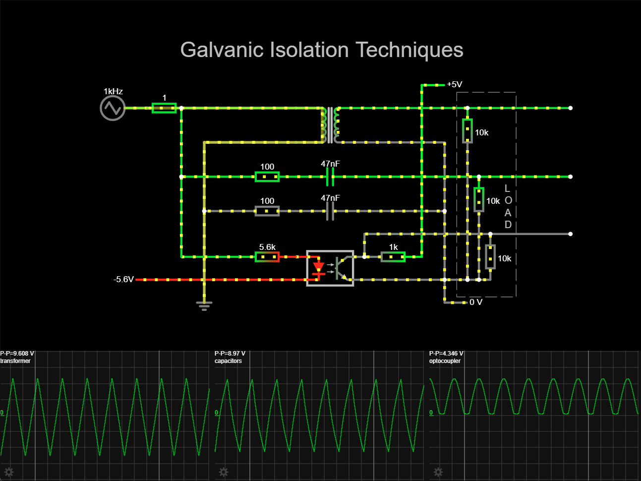
Wikipedia has a good summary of galvanic isolation techniques. Three basic unidirectional examples are shown above in a screenshot from the Falstad Circuit Simulator with a 1kHz triangle wave input.
If a DC voltage needs to be passed where the underlying approach does not support it then modulation of the baseband signal with successive demodulation is a solution - this is often implemented in an integrated circuit.
Magnetic Field
- Transformers are a well-known form of isolation.
- These can be found in power supplies, some audio equipment especially for low-level signals like microphones, twisted pair ethernet, traditional (copper-based) telephony and 110V safety isolation transformers.
- Transformers do not pass a DC voltage.
- This underlying isolation barrier is used in semiconductor isolators produced by Analog Devices.
- Relays are another option for low-rate on/off operation.
Electric Field
- Capacitors can be used to couple a signal via their internal electric field.
- Capacitors do not pass a DC voltage.
- This underlying isolation barrier is used in semiconductor isolators produced by Texas Instruments, Onsemi Wurth Electronik, for example.
Electromagnetic Radiation (light)
- Opto-isolators (or optocouplers) use visible or infrared light with a sensor in an enclosure.
- They are found in equipment using DIN MIDI (the Microrack midi->cv module has one for its TRS input) and switch-mode power supplies.
- Opto-isolators can pass DC.
- Simple devices are challenging to tune for linear (analogue) use, especially as the opto-isolator ages.
- The sensor type differs depending on the frequency requirements. Phototransistors are common up to around 50kHz, photodiodes (with amplification) beyond that.
- Depending on how these are used they may invert the signal.
Hardware Setup
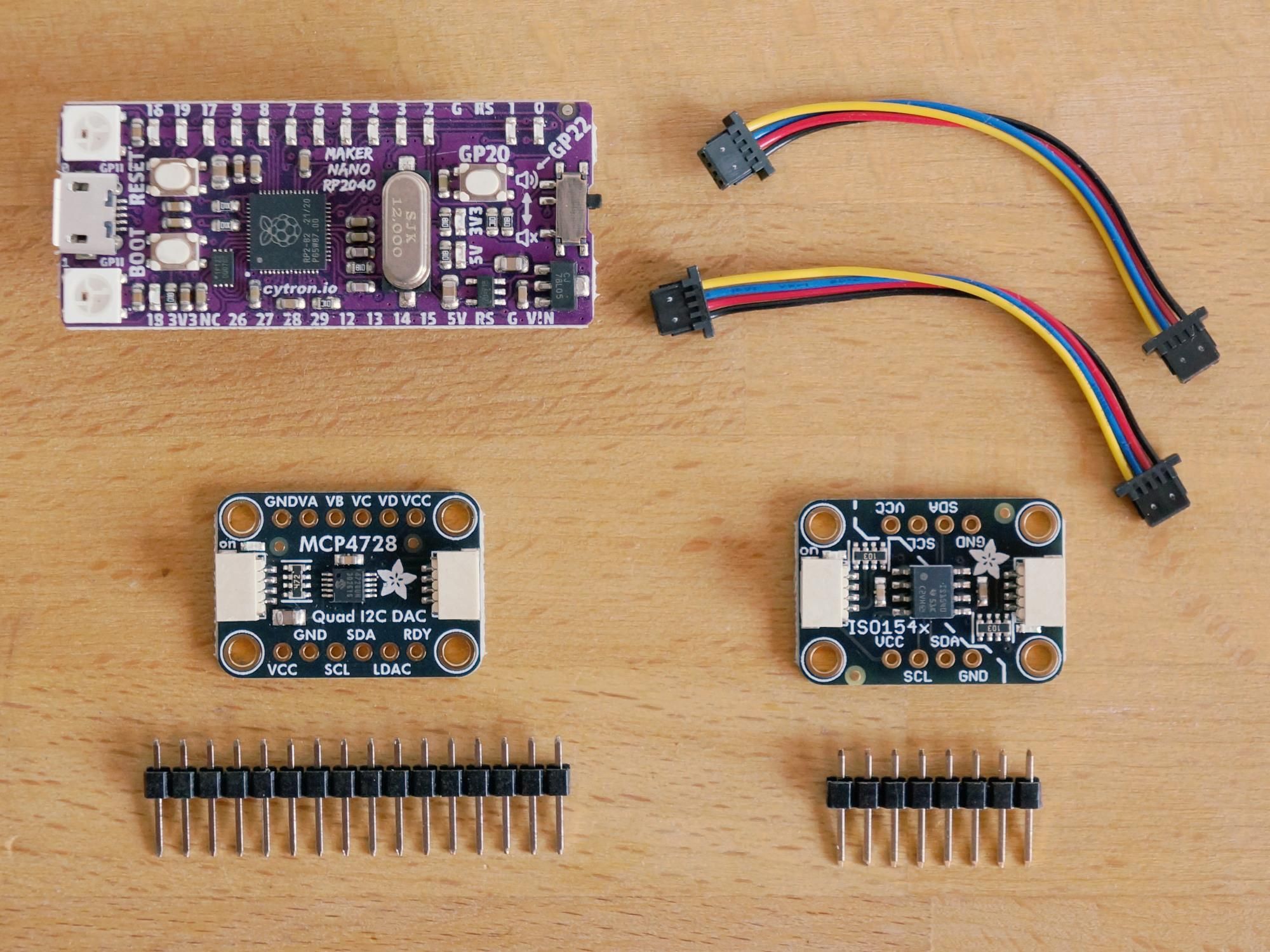
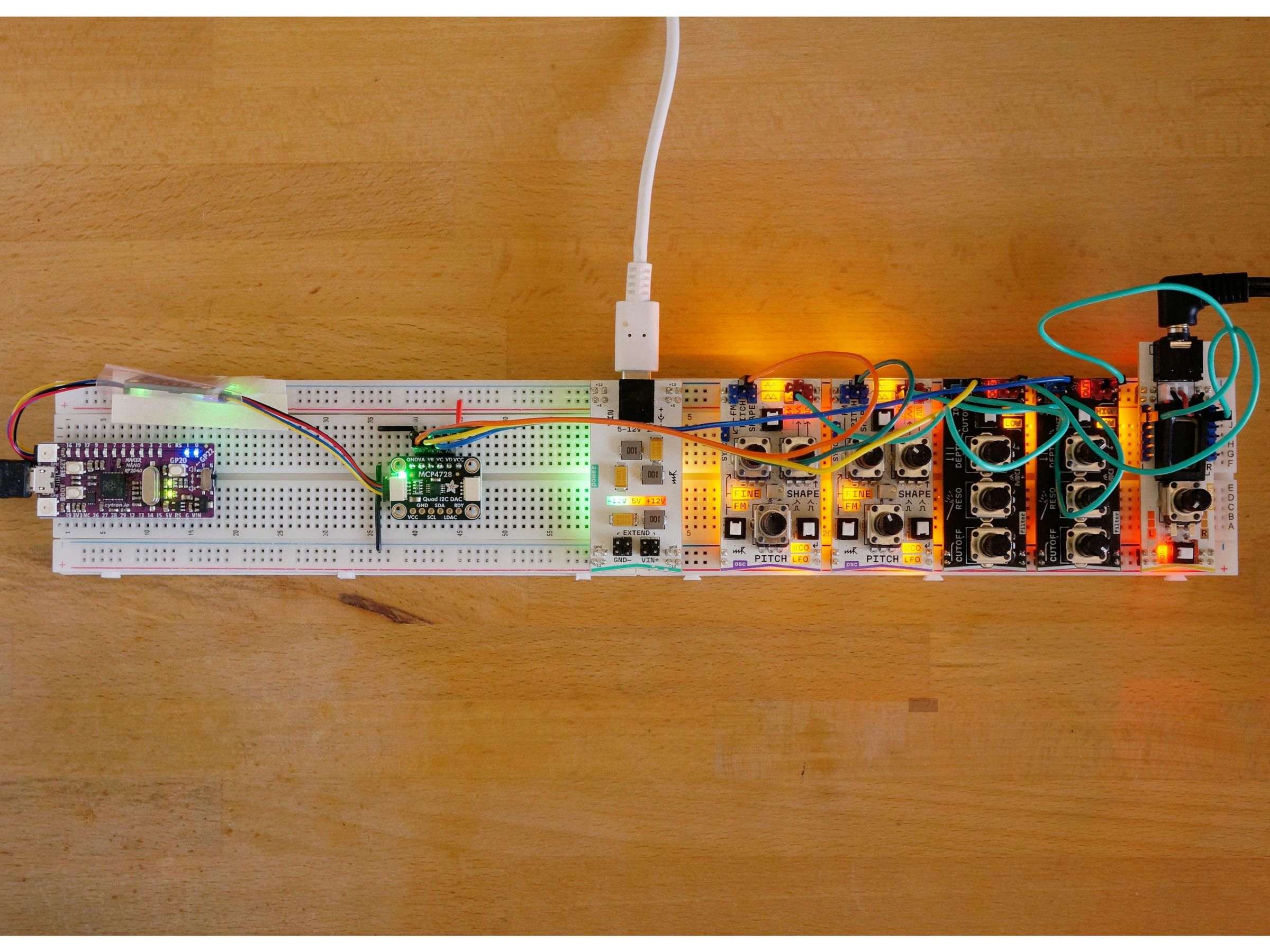
The non-Microrack components and hardware setup are shown in the photographs above. Two full-size breadboards are needed for all the components.
The Adafruit MCP4728 board needs to have a row of six header pins soldered to the top row (GND to VCC). Adafruit have a good guide on how to do this: How to Solder Headers. If the bottom row is attached then the board must be placed on the breadboard across the central gap.
The Cytron Maker Nano 2040 board, Adafruit MCP4728 board are inserted into the left breadboard. The Adafruit ISO1540 board is not connected to the breadboard and has been placed inside a piece of pink anti-static bag sealed on one side with masking tape to reduce the risk of something conductive touching the underside and shorting the pads. The Cytron board is connected to the Adafruit ISO1540 with a STEMMA QT cable, another cable connects the Adafruit ISO1540 to the Adafruit MCP4728.
The Adafruit MCP4728 has a six pin header on the top with the following pins from left to right.
- GND two** black solid cores wires to GND rail.
- VA to oscillator 1 PITCH (orange wire).
- VB - to filter 1 CUTOFF (yellow wire).
- VC to oscillator 2 PITCH (green wire).
- VD to filter 2 CUTOFF (blue wire).
- VCC red solid code wire to +5 rail. Do not connect this if the isolator is not in use***.
A Microrack power module bridges the two breadboards providing the +12V, +5V and -12V power to the breadboard rails. This must be plugged in first before the other Microrack modules.
The pair of oscillator modules, the pair of filter modules and the output 3.5 module are inserted into the right breadboard with some spacing to help a little with cooling. The oscillator's sawtooth output is connected to the filter's IN, the filter's OUT is connected to one of the output 3.5's L+R inputs. The oscillators are in VCO/FINE/bipolar mode (line passing through triangles). The filters are in LOW pass mode with maximum DEPTH set and minimum CUTOFF. The output 3.5 is in MONO mode to mix the two notes together - stereo is fun with its extreme separation too.
The oscillators need to be accurately tuned and the filters set to the same values to ensure a note sounds the same regardless of whether it's generated by oscillator 1 or 2.
Modules: power oscillator (osc) x2 filter x2 output 3.5
USB (5V)**** measured current: 0.66A.
This patch (module configuration) is good for showing the high degree of hardware duplication required for true polyphony and explaining why early polyphonic analogue synthesizers were expensive.
** Using one ground wire with a bend in it is a better solution for reducing the number of (fairly high resistance) breadboard connections.
*** The Adafruit MCP4728 would normally be powered from the STEMMA QT power but with the isolator it's "reversed" and the local power to Adafruit MCP4728 powers half of the isolator.
**** The power module was powered by a 12V wall-wart PSU for this project.
Installing Software
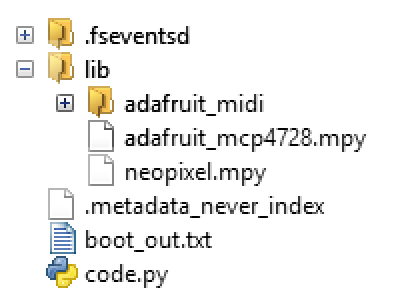
If you are not familiar with CircuitPython then it's worth reading the Welcome to CircuitPython guide first.
- Install the latest version of CircuitPython (10.2.1 on April 2024) from https://circuitpython.org/ - this process is described for a similar RP2040-based board in Introducing Adafruit Feather RP2040: Installing CircuitPython.
- adafruit-circuitpython-cytron_maker_nano_rp2040-en_GB-10.2.1.uf2
- Verify the new installation by connecting to the serial console over USB. The REPL prompt shows the version number. The version can also be checked by inspecting the boot_out.txt file on the CIRCUITPY drive.
- Install these libraries from a recent bundle from https://circuitpython.org/libraries into the lib directory on CIRCUITPY:
- adafruit_mcp4728
- neopixel
- adafruit_midi
- Download the midi-cv.py file to CIRCUITPY by clicking on the Raw button on the page and then Save link as...
- Rename or delete any existing code.py file on CIRCUITPY, then rename midi-to-cv.py to code.py. This file is run when the CircuitPython interpreter starts or reloads.
- Unmount (eject) the CIRCUITPY drive.
The versions used for this article were:
- CircuitPython: 10.2.1
- CircuitPython library bundle: adafruit-circuitpython-bundle-10.x-mpy-20260620
Software Functionality
The v1.0 software has the following functionality.
- Processes MIDI note on/off messages to produce
- CV - control voltage between 0.000V and 4.083V;
- GATE - 0V or 4.88V;
- VELOCITY - velocity value scaled from 0V to 4.88V;
- ENV - a synthio-generated ADSR envelope with attack and release controlled by MIDI cc73 and cc72, respectively.
- Can output to one or more DACs. Currently supports MCP4728 and internal DAC (where available, untested).
- Supports voice assignment to multiple outputs for polyphony.
- Support MIDI pitch bend.
- Indicates note and velocity on any RGB LEDs using colour and brightness on the microcontroller board and for any boards with GPIO LEDs pulses these to indicate notes are playing.
The patch needs to be powered for the software to see the MCP4728 DAC on the i2c bus when the program starts on the Cytron microcontroller board.
Demonstration
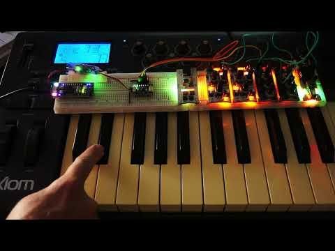
The video shows the Cytron Maker Nano 2040's CircuitPython program in action converting the MIDI messages from the M-Audio Axiom MK II controller (routed via desktop PC) to a pair of pitch control voltages and envelopes produced by the Adafruit MCP4728 board which is connected via the Adafruit TI ISO1540 isolator board.
- 00:00 Note range C2 to C6.
- 00:26 Some dyads**.
- 01:01 Adjusting attack/release times.
- 01:11 Playing notes with overlapping releases.
- 01:45 A poor rendition of chopsticks.
** If the consonance and dissonance aren't very similar to this example then your oscillators aren't tuned well!
Synthio Envelope
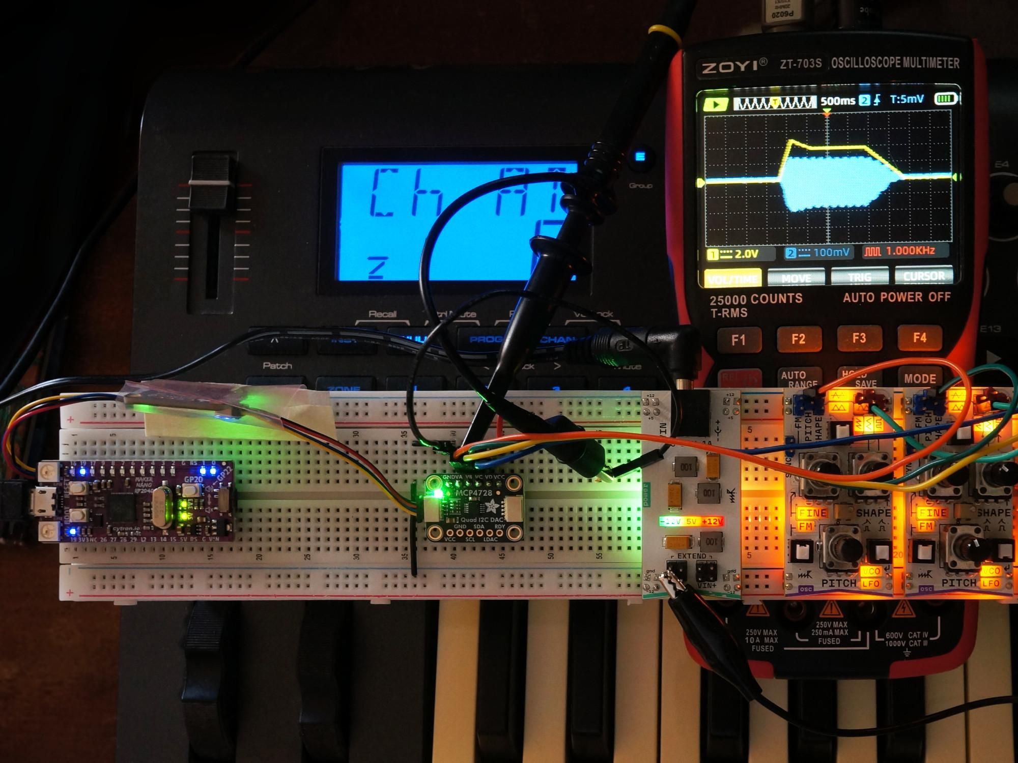
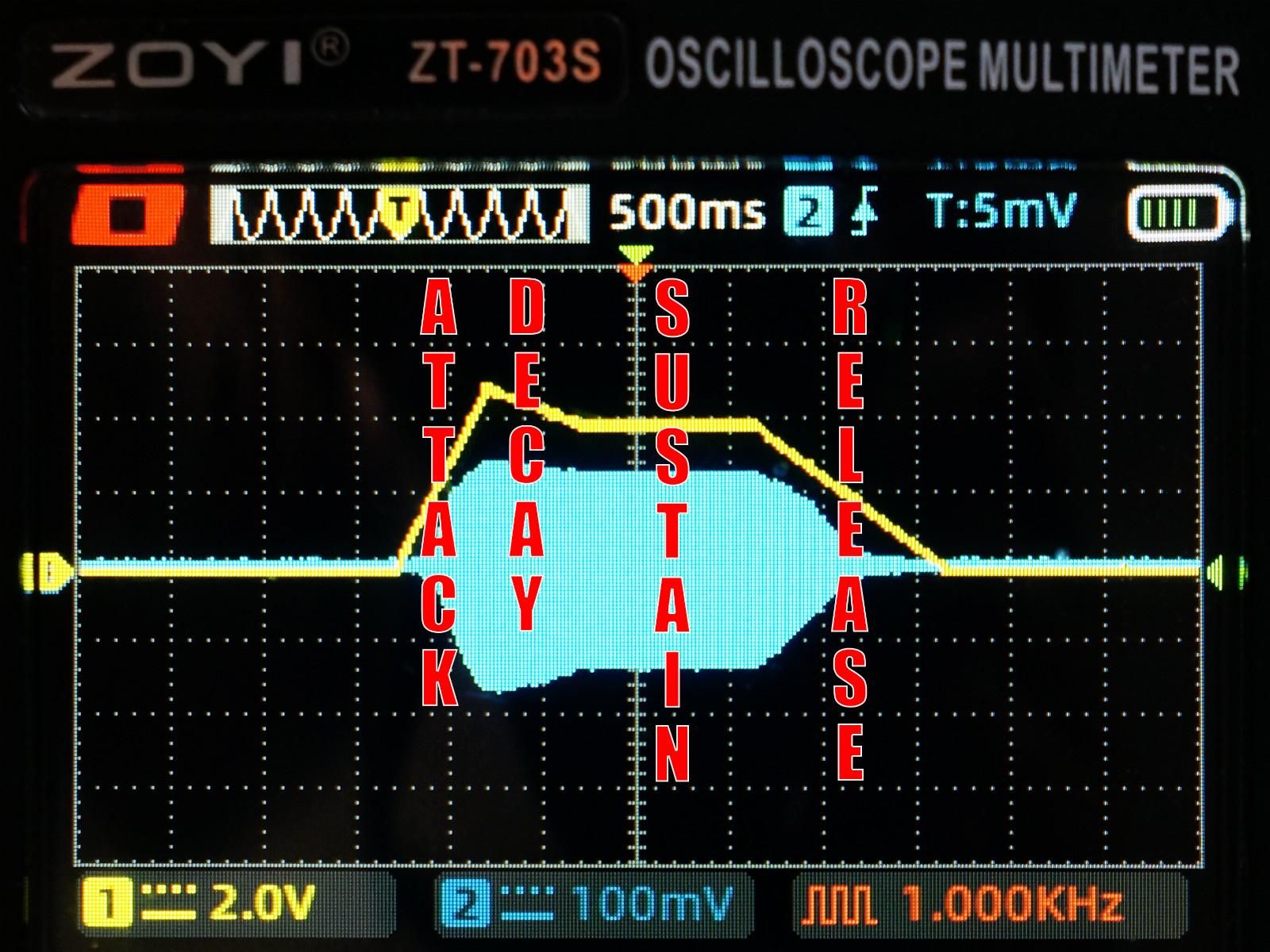
The program is configured to output a pair of control voltages with envelopes using the four outputs available on the Microchip Technology MCP4728.
These are assigned in order to the A, B, C and D channels on the MCP4728 DAC.
The envelope is generated by the synthio library in CircuitPython. Examples can be seen in the photographs above with the oscilloscope showing the audio output in cyan and the envelope voltage in yellow.
The control voltages are output using the DAC's internal reference to get good accuracy. The envelopes are output with the DAC's power supply as a reference. It measured 4.88V, 2.4% below the ideal 5.00V.
Checking the DAC Output
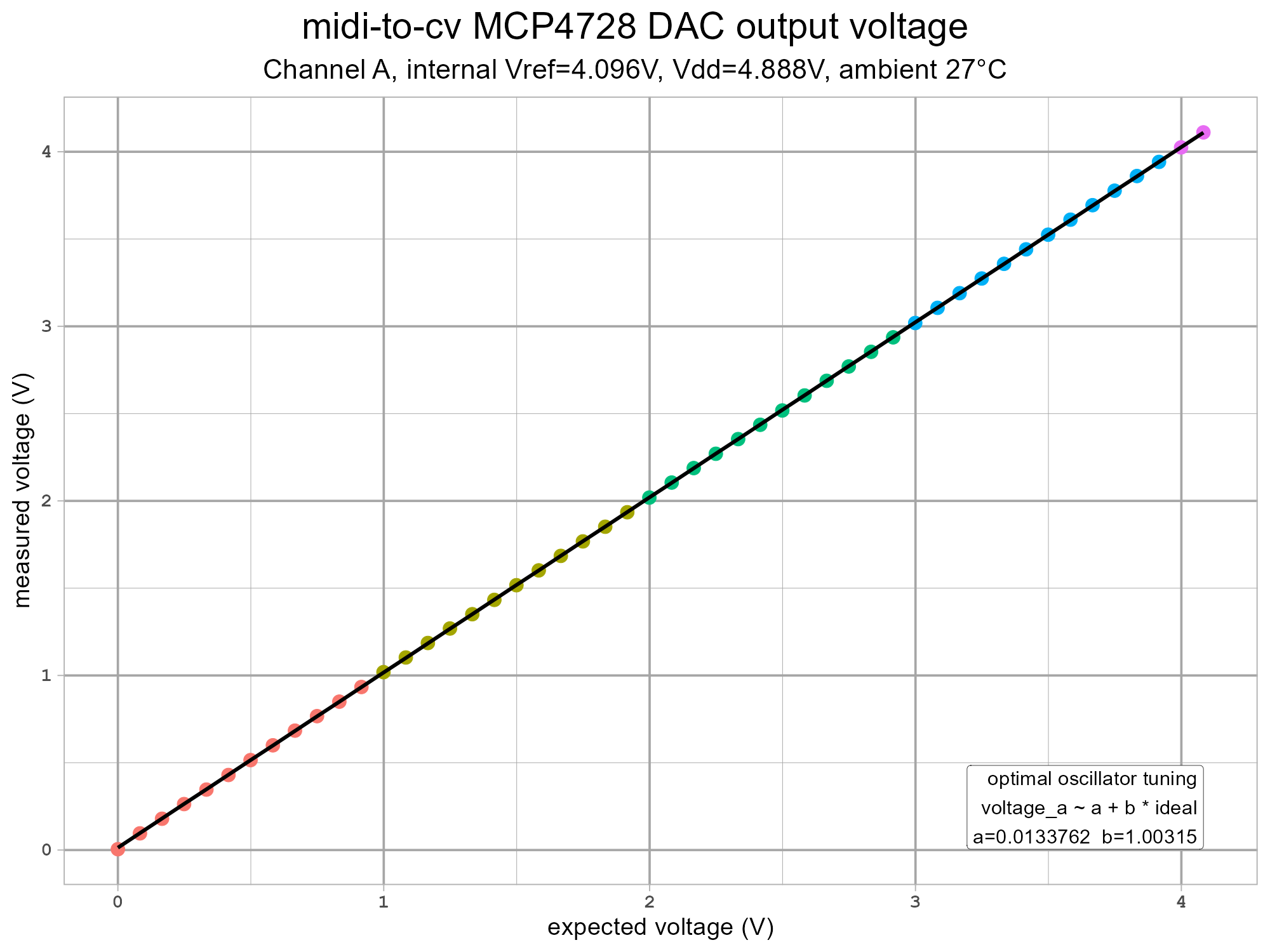
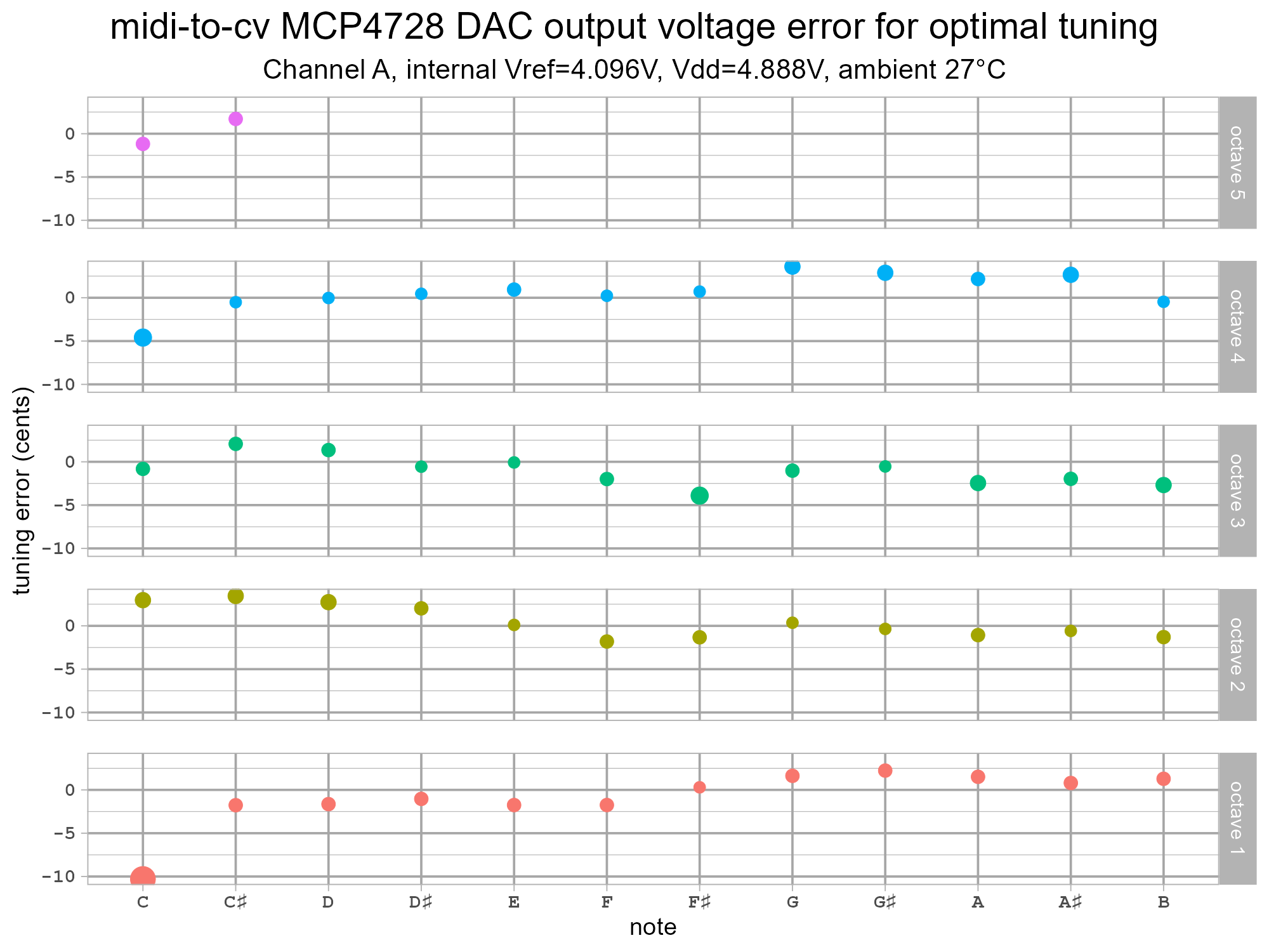
The MCP4728 DAC using the internal reference with gain 2 covers the range 0.000V to 4.096V. For a 1V per octave range the voltage range covers 4 octaves and one extra semitone (1/12 = 0.8333V). The 12bit resolution of the DAC makes each step 1mV which equates to 1.2 cents.
The MCP4728 datasheet discusses the linearity of the outputs in the 6.6 Gain Error section.
For the MCP4728 device, the gain error is not calibrated at the factory and most of the gain error is contributed by the output buffer (op amp) saturation near the code range beyond 4000. For applications that need the gain error specification less than 1% maximum, a user may consider using the DAC code range between 100 and 4000 instead of using full code range (code 0 to 4095). The DAC output of the code range between 100 and 4000 is much more linear than full scale range (0 to 4095). The gain error can be calibrated out by using applications’ software.
The first plot shows the voltage from channel A (with an oscillator module as load) for all of the playable notes from C1 (ideal 0.000V) up to C#5 (ideal 4.083V). The values look reasonable but this presentation isn't great for showing the small errors. The second plot assumes the user has optimally tuned a (perfect) voltage-controlled oscillator to the DAC output. The error is mostly a few cents (1/100th of a semitone) with the exception of the first note.
The warning in the datasheet is demonstrated here with C1 at 0.000V (DAC code 0) ending up 10 cents flat. One way to avoid this is to set the BASE_NOTE to be a semitone lower than the desired lowest note to avoid this bum note.
The oscillators can then be tuned against the C notes.
The measurements in the plots were taken using an (uncalibrated) AstroAI DM6000AR from the breadboard rows next to the DAC with the patch shown in this article. The power supply was a cheap 12V wall-wart. The 3.5mm audio output was connected to desktop PC speakers via a ground loop isolator. The audio wasn't active during the measurements. The values shown on the multimeter were very stable with either no change in the last digit or the value changing by 1 for a handful of values suggesting an in-between value.
Noise/ripple from the Microrack power module combined with some from the 12V power supply was evident on the DAC output. A Zoyi-703S showed this as 24mV peak-to-peak, 7mV RMS with dominant frequency around 100kHz. For comparison the power supply to the DAC using +5V rail was approximately 68mV peak-to-peak, 20mV.
Going Further

Some ideas for software enhancement.
- If you have the ESP32-based Microrack midi to cv module compare the functionality (using provided firmware) and outputs of the this vs the project in this article.
- Add more MCP4728 DACs for even more outputs. One can be added to the second connector on the Cytron Maker Nano 2040 with its own isolator or more can be added on the same i2c bus by assigning a new i2c address to the DAC to make them unique (per bus).
- Implement MIDI control over the decay time and sustain level.
- Make the envelope respond to MIDI note velocity.
- Enable use/output of the modulation wheel.
- Output synthio's LFOs as (unipolar) outputs.
- Implement portamento for monophonic use.
- Implement a channel pressure (aftertouch) output.
- Use the GP20 button on the Cytron Maker Nano 2040 for something interesting.
- Check how fast i2c can run with the isolator and cabling. Note: the RP2040 SDK providing the i2c functionality in CircuitPython does not necessarily run at the requested rate.
- Look at relic-se's KeyManager library to see if it can be used/adapted easily for generating control voltages for an i2c DAC.
Other articles/videos on Microrack:
- DIY Electronic Music Blog: Microrack – First Impressions
- Parks and Rex: Microrack! - Demo and First Thoughts (YouTube) - more modules on display than just the Synth Starter Kit, at 03:53 the single breadboard is replaced by the rack chassis.
- Cinematic Laboratory: MicroRack - Modular For The Masses? | Starterkits Ep. 14 (YouTube)
- Nosnibor Senoj (YouTube)
- an early Microrack patch
- two oscillators & two oscillators (again)
- Andrew Huang: Modular synthesis EXPLAINED (YouTube) - not specifically about Microrack but the modular concepts are still applicable despite Eurorack being used for examples.
- An (unofficial) Microrack patchbook app.
Some other MIDI to CV converters:
- Eurorack
- AMYboard
- Instructables: MIDIXCV - MIDI to Multiple Control Voltages Converter
- Behringer CM1A High-Resolution 16-Bit MIDI to CV Converter Module
- Synthotek: MST MIDI to CV Converter Kit
- Arturia KeyStep mk2
Some articles/videos on CircuitPython's synthio:
- Adafruit Learn: Audio Synthesis with CircuitPython synthio
- todbot's CircuitPython Synthio Tutorial & CircuitPython Synthio Tricks - a work in progress.
- Adafruit Learn: Faderwave Synthesizer
- Adafruit Learn: Guitar Synth with CircuitPython SynthIO
- Adafruit Learn: Computer Perfection Synthesizer
- todbot: Pygamer wavetable renderer + synth for CircuitPython synthio (YouTube)
- ReLiC: CircuitPython Synth Voice Library Deep Dive (YouTube) - a CircuitPython synthvoice library to simplify synthio patch creation.
- Instructables: Creating Synthesizer Sounds Using CircuitPython Synthio With Pimoroni PGA2350 or Cytron Maker Pi Pico