Mini Home Automation Featuring Gen4-uLCD-32DT
by 4D Makers in Circuits > Arduino
521 Views, 0 Favorites, 0 Comments
Mini Home Automation Featuring Gen4-uLCD-32DT

This Mini Home Automation project uses gen4-uLCD-32DT to control the lights in different parts of the house model. This demonstrates how to use the GPIO pins of a certain programmable module or board as an output. Different parts of the mini house can be controlled by using the graphical user interface of the gen4 HMI module.
How It Works
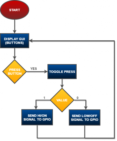
The resistive touch of gen4-uLCD-32DT displays the graphical user interface which can be pressed. Upon pressing each winbuttons, the processor will send a high signal to the respective GPIO pins to turn on the LED. The winbuttons also toggle the state of their respective GPIO pins.
Build
Components
- gen4-uLCD-32DT
- gen4-PA and FFC Cable
- uSD Card
- 5 x White LEDs
- 5 x 100 Ohms Resistors
- Connecting Wires
- Micro USB Cable
- 5V Power Supply
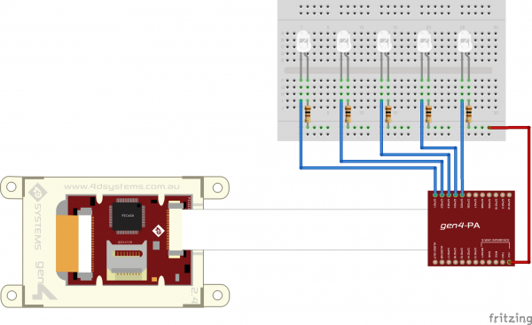
Build the circuit as shown in the diagram above.
Program
Download the project code here.
Open this project using Workshop 4. This project uses the Visi Environment
You can modify the properties of each widget.
Click on the “Build Copy/Load” button.
Connect the display to the PC using uUSB-PA5 and a mini USB cable. Make sure that you are connected to the right port. Red Button indicates that the device is not connected, Blue Button indicates that the device is connected to the right port.
Now click on the “(Build) Copy/Load” button.
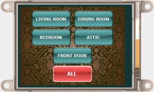
Workshop 4 will prompt you to select a drive to copy the image files to a uSD Card. After selecting the correct drive, click OK.
Properly unmount the uSD Card from the PC and insert it to the uSD Card slot of the display module. The image above must appear on your display after completing the steps above.
Demontration
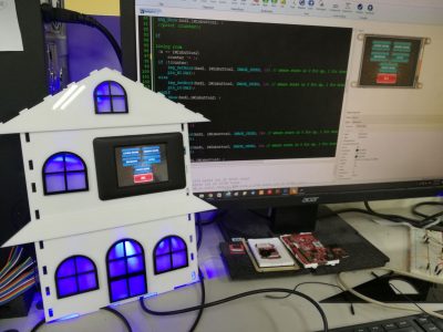
An acrylic cut of a mini house model is used to showcase the function of this project.