Mini PowerMac G3 Blue & White NUC Hackintosh
by GregO29 in Workshop > 3D Printing
1374 Views, 24 Favorites, 0 Comments
Mini PowerMac G3 Blue & White NUC Hackintosh
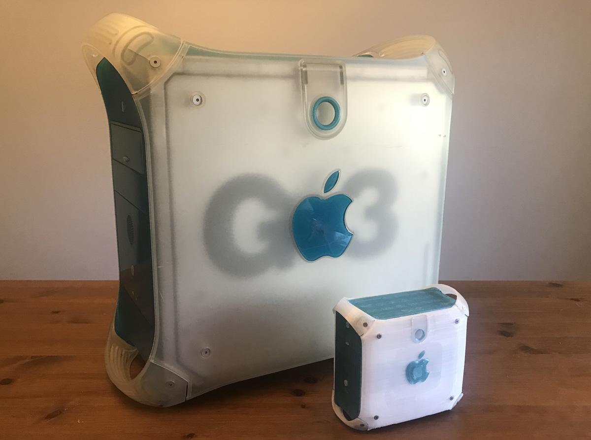
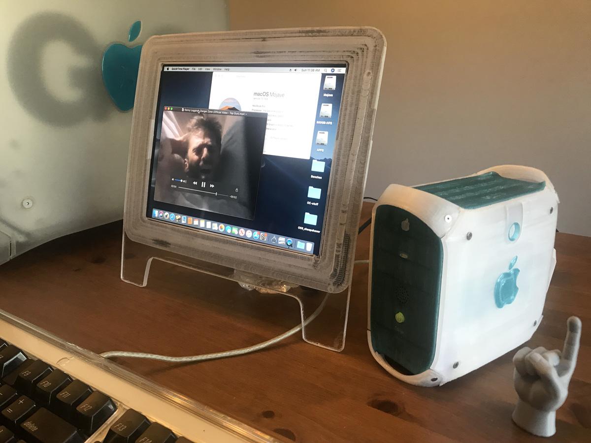


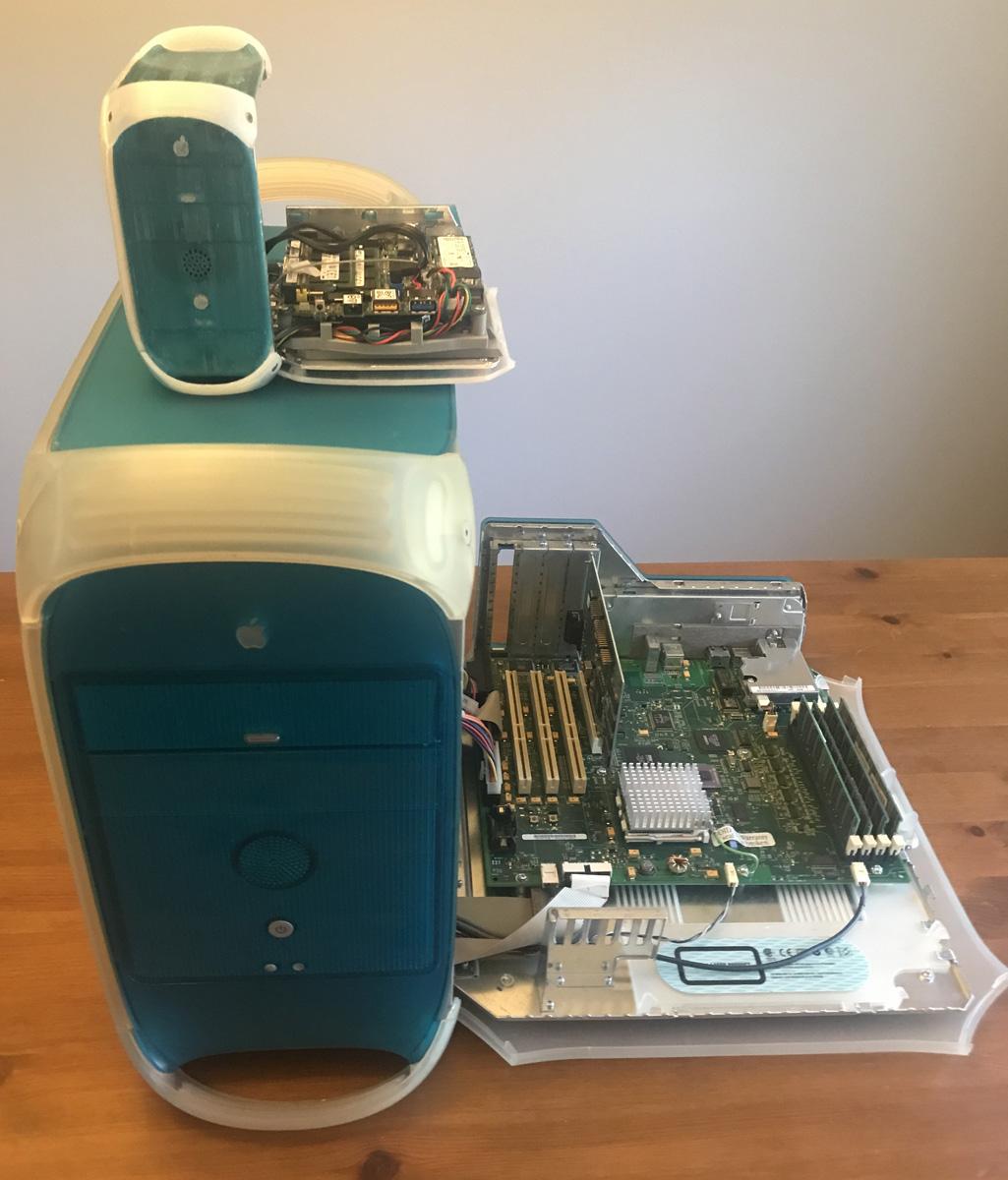


This is the story of another Hacintosh mini build. I had this on the back burner for quite some time, never having owned a PowerMac G3/G4 previously. I started looking for 3D models of this case style, but again was disappointed with the offerings available. I found some sample models online, so that was a good place to start. I had to purchase an actual computer so I could measure and possibly 3D scan it myself. I could not find a B&W and had to settle for a "graphite" model. I then tried to take photos from every angle and use photogrammetry software to construct the model. That was an utter failure, so I just used isometric photos of each primary axis to build it best I could. As this build was nearing completion, I did finally acquire an original 350MHz Blue and White Powermac1,1. The PETG colored filament I have from another project is close, but maybe "Bondi and White" is a better description.
Downloads
Supplies


Electronics:
- NUC mini computer, includes mainboard/CPU, RAM, SSD, active cooler
- 12v mini fan (40x40x10mm)
- additional 2.5 SATA storage device
- SPST momentary switch (power button)
- 5v mini LED
- 8 Ohm 1W speaker
- USB to headphone/mic adapter
- PAM8304 audio amplifier board
- 3 10K resistors
- misc wires and connectors
- small piece of PCB perf board or salvage
- 2 IPEX antennas for wifi and bluetooth
Mechanical parts:
- Lots of tiny screws, both wood and metal type threads
- 2 ball pen springs
- 2 uncoated metal paperclips
- Sheet of rubber/silicone padding (prefer clear or white)
- Aluminum foil tape (or silver type paint)
Tools:
- Soldering iron with solder
- Side cutters/snips
- 3D printer, various filaments required
- Various screwdrivers (bits)
- Pliers or Needle-nose
- X-acto knife (or other tools for fine detail cutting)
- torch style lighter or reflow heat source (for melting/adjusting parts)
- Hot glue or some other liquid adhesive, I do not recommend crazy glue, as it leaves residue/ghosting on 3D prints
- Time and Patience
List of 3D Printed Parts


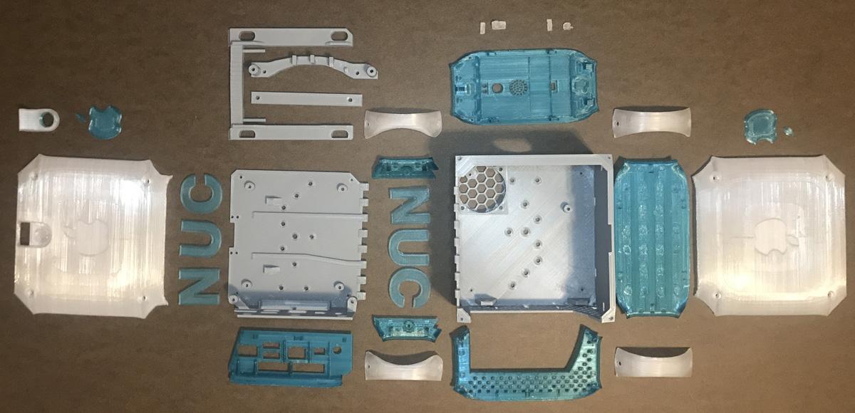
3D printed parts and colors (part - description):
PLA Gray
- ga - box
- gb - door
- gc - latch
- gd - front motherboard mount
- ge - rear latch cover
- gf - HD mount bracket
- gg - special opening tool
PTEG Colored (blue, bondi blue)
- ca - ring
- cb - front
- cc - top
- cd - back
- ce - IO plate
- cf/cg - 2x bottom
- ch - 2x fruit logo (2 piece)
- cj - 2x NUC logo (3 pieces)
PTEG Clear/transparent
- ta - latch ring
- tb - side open
- tc - side closed
- td - 2x upper handles
- te/tf - 2x lower handles
- tg - Power button
- th - fruit logo
- tj - 2x fake buttons
Some More Info
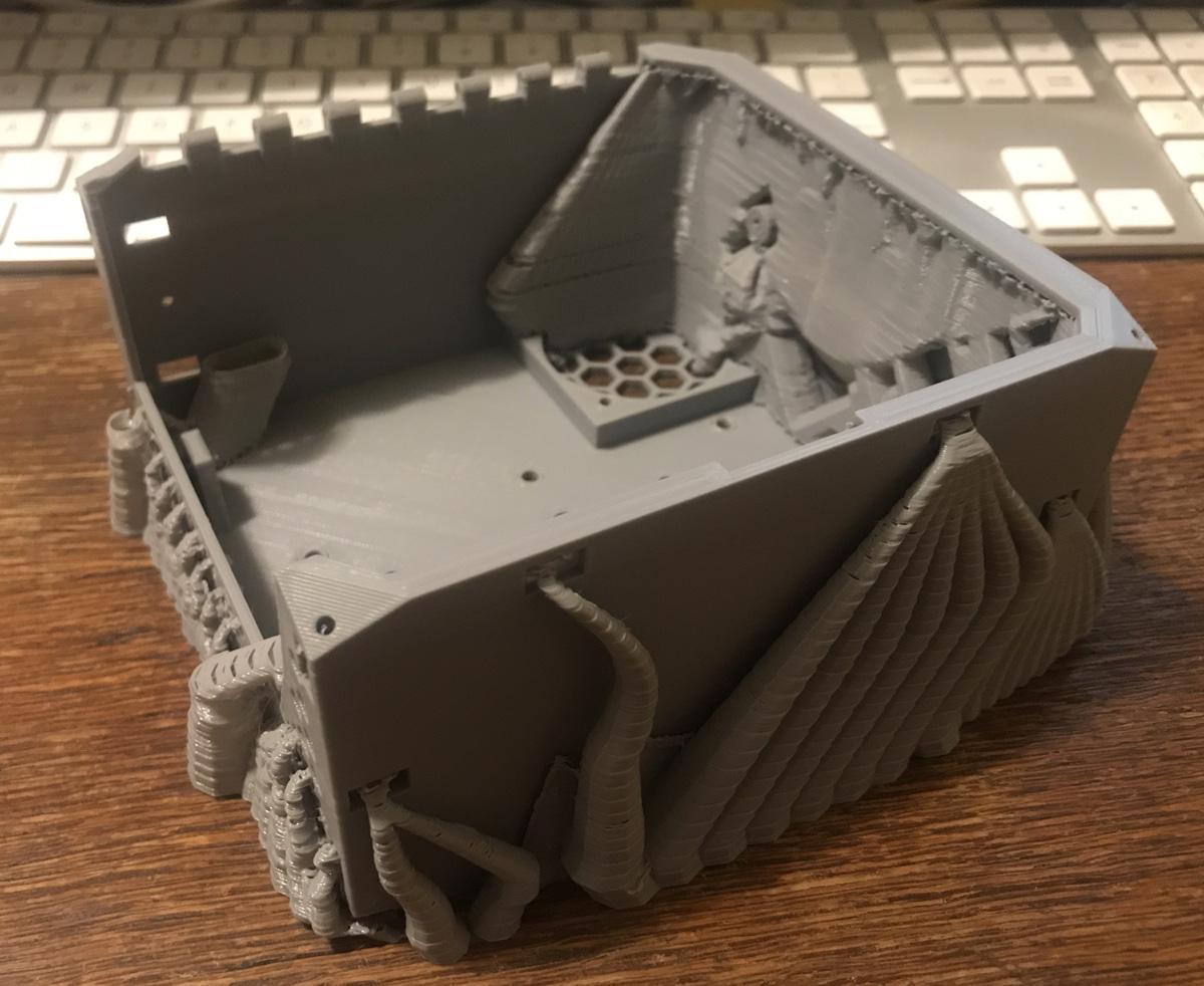
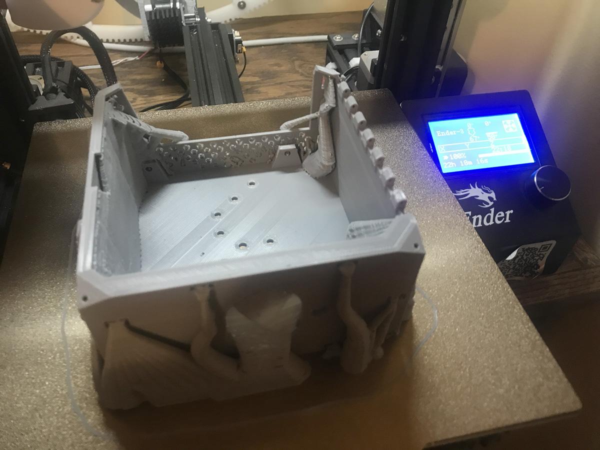

Gather your materials, download the 3D models supplied, and start printing. There is very little to build as far as electronics go, so you should have ample time to get everything ready while you wait for 3D prints to finish. Once your 3D prints are finished, clean and de-burr them all, polish and smooth to your own preferences. I tried to put these in logical order for the best assembly, so some of the photos are taken after I had to backpedal on some of the steps.
Which NUC or mini-pc motherboard you choose will impact what other accessories you can utilize. My NUC5i5 has several internal ports that I used. The standard front panel, and a dual USB2.0 header. Since the clearance is so small to get everything to fit, I cannot utilize either front USB port nor the headphone jack. Thus a USB to headphone adapter is utilized on the internal USB2.0 header and the amplifier draws power from the 2nd USB port. The internal fan draws power from the Front Panel port. Power button and front LED are connected to the internal front panel port. This NUC also has a SATA and power ports for a secondary 2.5inch SATA drive. You may need to adjust the 3D models for the rear ports to match your computing device and the speaker you choose.
Let me talk about small screws for a moment. I wish I knew where to order them from, or how to size them. If you look at my solar cooker Instuctables, you will see I have disassembled many mechanical hard drives over the years. I saved all the screws I removed. I have jars full of them. I have searched through them and found as many matching ones that I could to complete this project. If you know where else I could order from, please send me a note. Some have straight and narrow metal type threads (that bolt or threaded hole would take), and some have more wood type threads to go into softer materials like wood or plastic. Since this is all 3D printed plastics, you could use all wood type threads, but sometimes I feel the metal threads hold better on thinner plastic pieces.
Electronics Prep




Build the amp circuit
Since I can't use the headphone port due to space constraints, I opted for a USB to Audio device (headphone and microphone). I will only be using the headphone portion. Disassemble the cover, and de-solder the USB and sound jacks. I used the link below to determine using three 10K resistors to make the stereo output mono for the single speaker. This will only utilize half of the amplifier as well (single channel). Using the dual USB 2.0 header, I wired the plug for one port to the audio converter and the other to the amplifier. Solder the audio converter output to the amplifier input and the amplifier output to the speaker.
Stereo to Mono wiring: https://support.qsys.com/how-to-%7C-connect-stereo-outputs-to-mono-input
PAM8403 data: https://reversepcb.com/pam8403-amplifier-board/
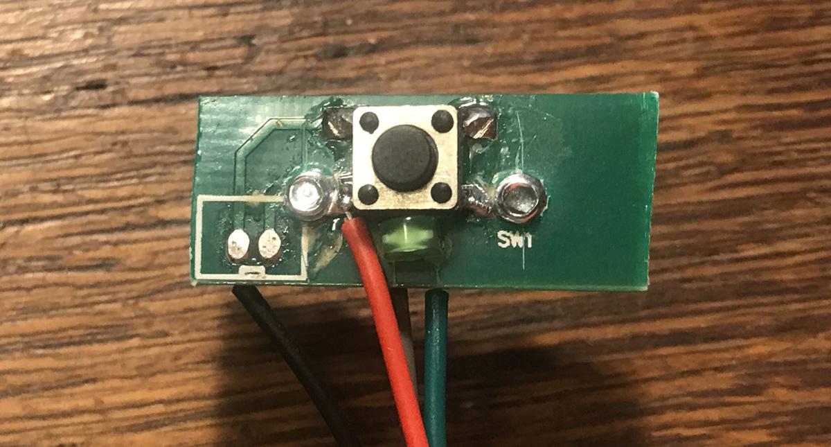
Build the button panel w/LED
I salvaged a piece of PCB with a button on it already. I drilled a couple holes for an LED and added the four wires for the front panel plug. I trimmed it down and added two holes for the mounting screws. Using other pins on the front panel plug (pin 9 for 5v and pin 5 for ground), I wired the connector for the 12v fan. It will be running on 5v, so slower, but more quiet.
Connect everything electronic and test it for functionality before we install it.
Start With the Base


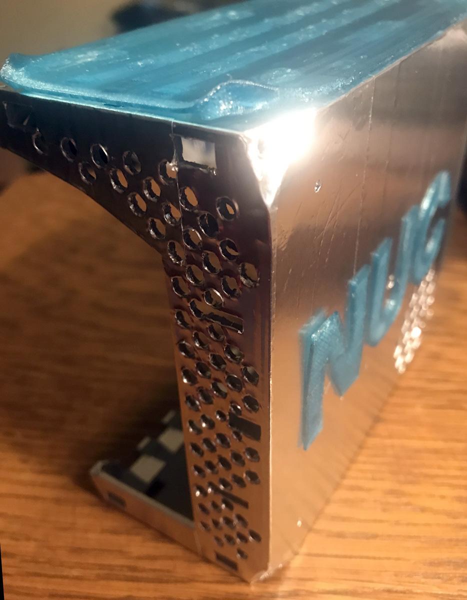


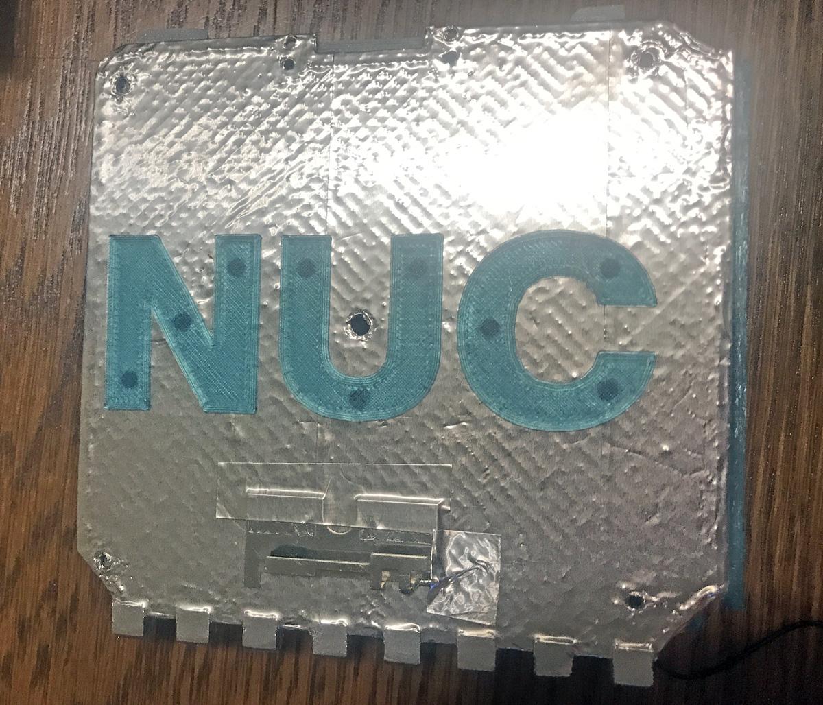
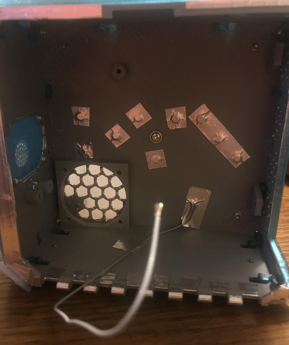
I used PETG for my "clear" and colored parts, you can use a natural PLA or some other filament of your choice. True Clear is hard to produce and discussion of production can get quite deep. I used a standard PLA gray for the simulated metal parts. I also wanted the reflectivity of aluminum/metal, so I covered my core element 3D prints in aluminum foil tape.
Start with the box (ga) and door (gb) by covering the outside in foil tape, then clearing all the holes with a sharp knife. You can try poking them through, but some have tight clearances with other parts, so best to just remove the hole coverings. As an alternate, you could spray paint or brush on silver type paint. Once the box and door are silvered, you can add the NUC logos (cj). The dots on the NUC logo are a little bit longer than the holes, so you can melt them to lock them in place. I used a blow torch type lighter to heat them, then flattened them with the butt end of a metal X-acto knife.
The only two holes missing from these pieces depend on the type and location you want to put the wifi/BT antennas. I salvaged my antennas from the original NUC case. Since we covered everything in foil tape, it is essentially now a Faraday cage, so we have to place the antennas outside the foil tape. I chose to mount mine near the bottom of each of the side panels. Since they are aluminum, they visually blend in with the foil tape. Drill a small hole where the wire will pass through to the inside of the box, and mount the antennas with some more foil tape. At this stage, I also put foil tape over the NUC logo legs on the inside, as any internal LEDs may show through. Then set these two parts aside for later.
Assembling the Door Latch


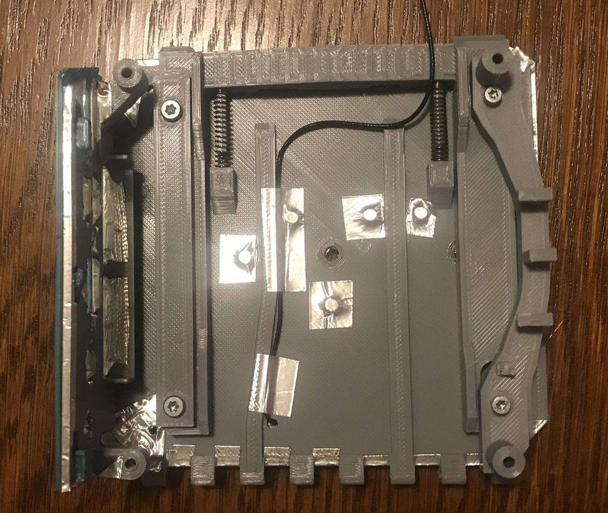
Begin with the outside door cover assembly. Start by inserting the ring (ca) into the latch ring (ta). Grab a paperclip and straighten it as smooth as you can. User a pliers to bend a short 90 degree bend at one end of the paperclip (about 1/8 to 1/4 inch long). Hold the paperclip over the cover (tb) and cut the paperclip off so about 1/4 inch goes beyond the hole (approximately 2 inches long before the bending). Insert the latch ring (ta) into the cover (tb), and gently insert the paperclip all the way through. If possible, bend it over so it does not fall out later. Again set this part aside for later.
Now add the locking mechanism. We need the door (gb) and the latch (gc) and two pen springs. Insert the springs onto the latch (gc) sticks, then loosely place the latch on top of the door. You will have to compress the springs one at a time to fit into the door, and drop down the latch into the keyed holes once your compress a spring. This should make sense with the photos. Now attach the two motherboard mounts (gd/ge) over the latch with 4 screws (wood type threads).
The colored IO shield (ce) should now be placed onto the door (gb) and locked in place (the tabs should make sense; you may have to clear some space in the holes, because after you add the foil tape, the tolerance is less). Then the door cover (tb) can be attached with 5 screws (1 wood type in the center inside, 4 metal type from the outside). The door is nearly complete for now, so set it aside.
Assembling the Box and Testing the Hinge


Locate the front panel (cb) and the fake buttons (tj - 2 pieces). The fake buttons (single high, dual low) should fit and not need any adhesive. I put a piece of tape over the back just to hold it in place while attaching it to the box. This piece can now be fixed to the box (insert tabs, lock upwards). Locate the top (cc) and lock in place by sliding forward. Locate the back (cd) and lock in place by sliding sideways/outwards. Locate the two bottom pieces (cf/cg). Make sure the side with the notch missing faces the door, and secure in place with two metal type screws. The left cover panel can now be installed with 1 screw from the inside of the box and 4 screws from the outside.
Next combine the box and door by flattening the other paperclip. Place the flattened paperclip along the outside of the hinge to cut the proper length (approximately 4.25 inches long). If you look at the lower rear of the box, you should see a gap where the paperclip can insert into the hinge. Align the door and box so the paperclip can be inserted, and slide the paperclip in. A bit of the paperclip may still be visible and that is fine, it should be covered by the lower rear handle. Test the door and latch. The door should swing open and closed without any binding. The latch should lock the door in place with an audible snap when closed all the way, and the door and latch should not wiggle. To open the door, insert the special opening tool (gg) and pry the latch open, the door should open. Once the door works well, remove the paperclip and separate the box and door. Set the door aside while we install the electronics.
Installing the Electronics


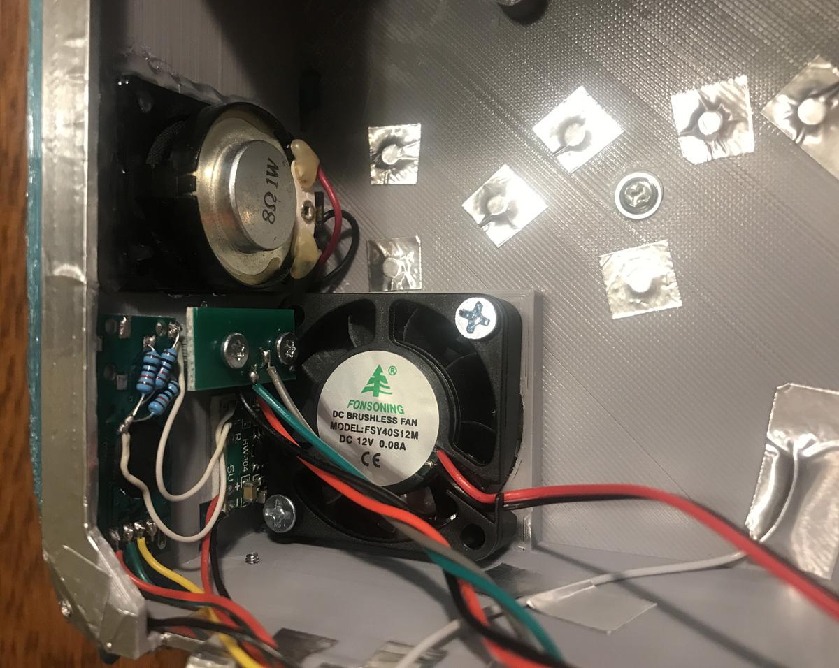
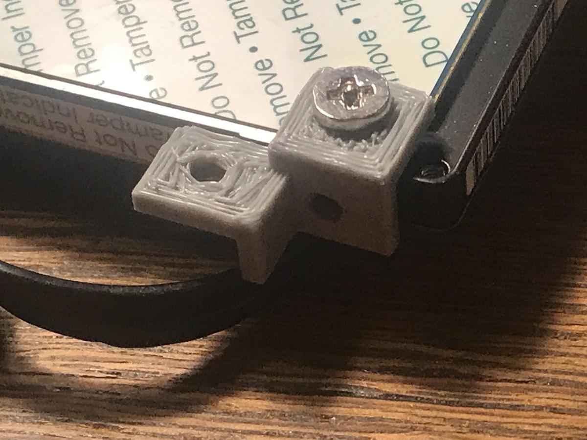
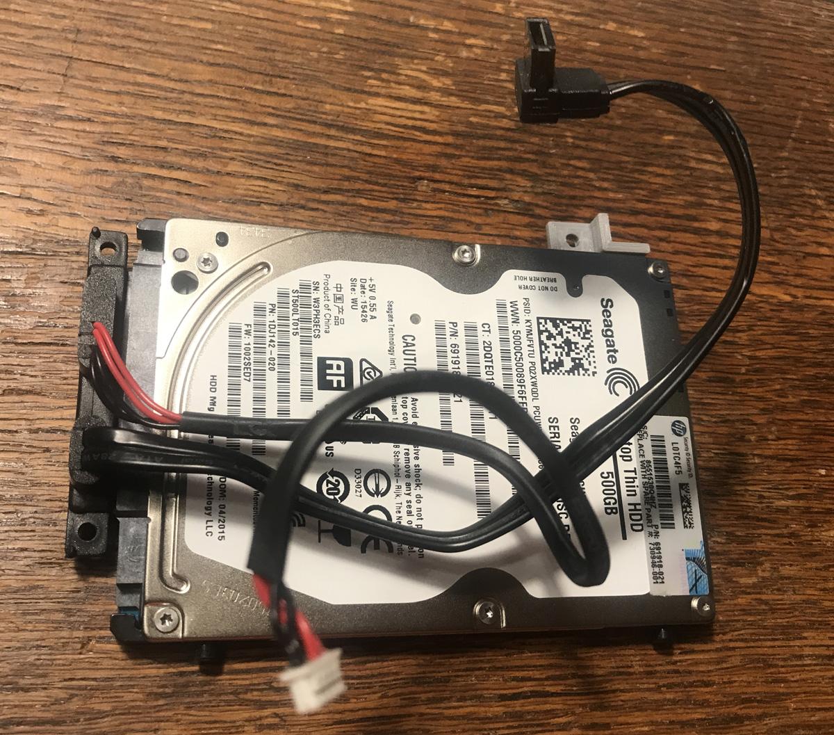

Install the speaker, amp, and USB audio converter (if used) into the box. I used a little hot glue to hold the speaker in place and some double sided foam tape to hold the amp and USB converter. Insert the clear power button (tg) and then install the power button board with two screws (wood threads). Install the Fan with two screws (metal or wood type). Installing the 2.5inch extra hard drive is easier to perform before we attach the door. Mount the hard drive support to the drive with a side or bottom screw (hard drive specific screw). I used to null screws (pegs) that were salvaged from a macbook, for the rear facing edge. Attached the hard drive power and data cable, insert the drive, and secure the bracket to the inside of the box.
The hard drive mount screws look like these:
This is for 3.5 drive, but look the similar https://beetstech.com/product/imac-27-inch-a1419-hard-drive-screws-923-0377
This is for 2.5 drive, but have a ridge https://www.amazon.com/Odyson-Screws-Replacement-MacBook-2009-2012/dp/B00ZYY442C
Join the Two Main Parts
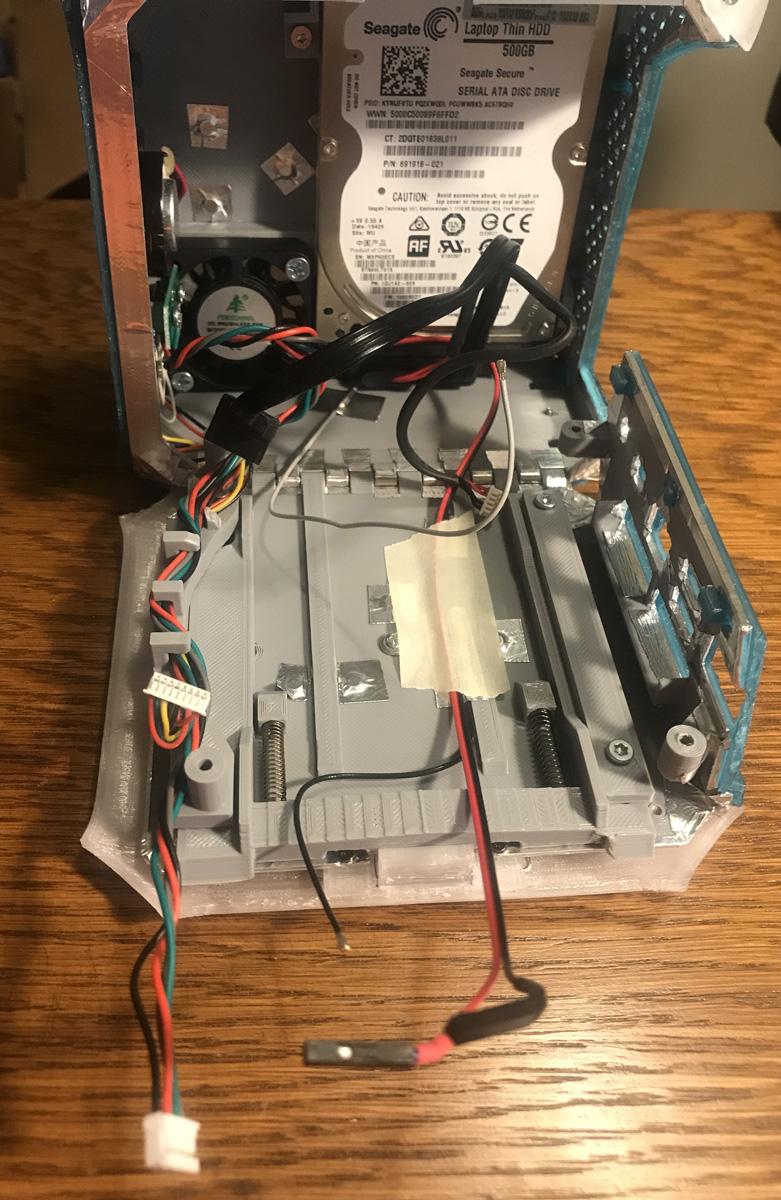

Attach the door to the box again with the long paperclip. Route the appropriate wires (front panel power/LED and the audio amplifier utilizing the internal dual USB header). My fan power is long enough to go under the motherboard, but the 2nd antenna is not, so it will be on top of the motherboard. Anything under the motherboard should be secured to the door so that it does not end up going into the fan and stopping airflow.
Install the NUC with 4 screws (wood type). The NUC I used has the wifi under the M.2 drive, so remove the M.2 drive to install the antenna wires (IPEX). Reinstall the M.2 drive. Connect all other wires. Clearance may be tight, check to see that the door closes without binding.
You Can Handle This
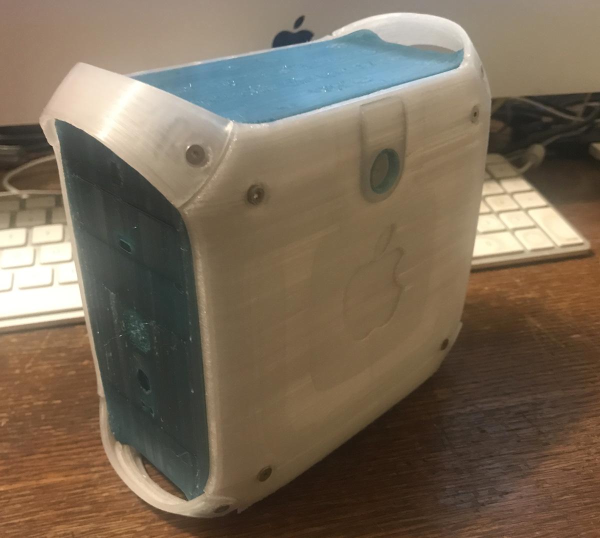
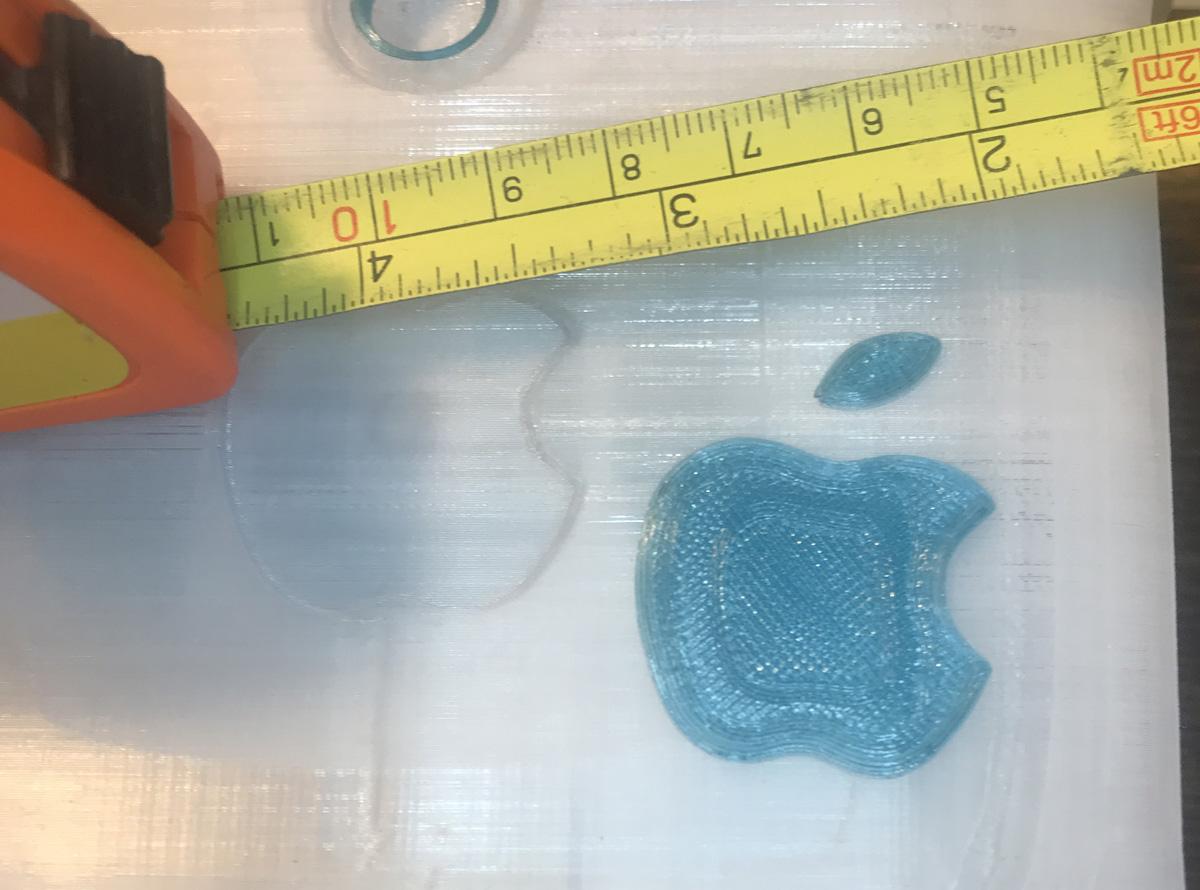


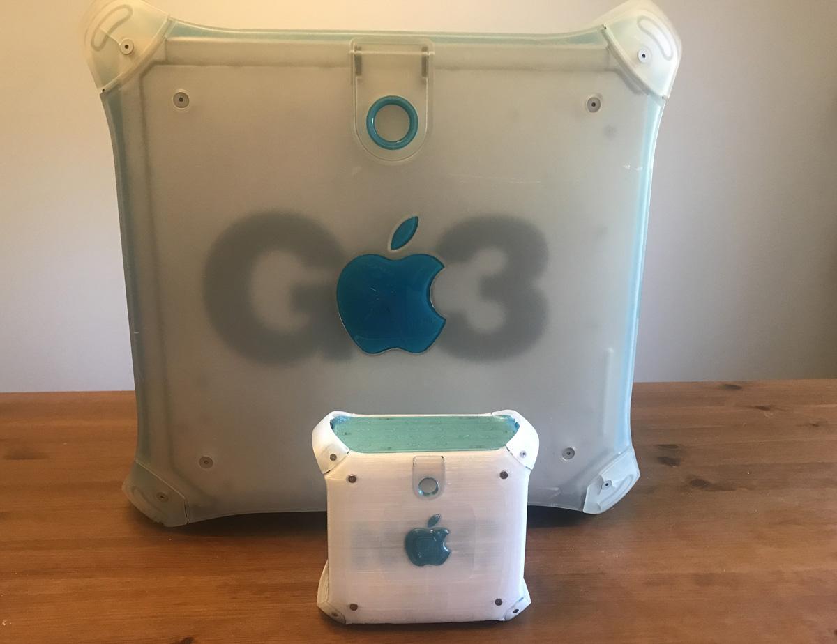
Finally add the two top handles (td) with 4 metal type screws. Add the bottom handles (te/tf) with 4 metal type screws and they should only fit on one way (notched for the door). Time for some hot glue or adhesive. Warm up the hot glue gun. Locate the 2 fruit logos (ch) and the front logo (th). That is 2 quarter sized pieces and 3 tiny pieces (easily lost). Not much adhesive is needed, just a tiny drop should do. This tiny PC will still slide around on a desk, so the rubber padding should go on the bottom of the lower handles. Cut and trim to size.
Hackintosh


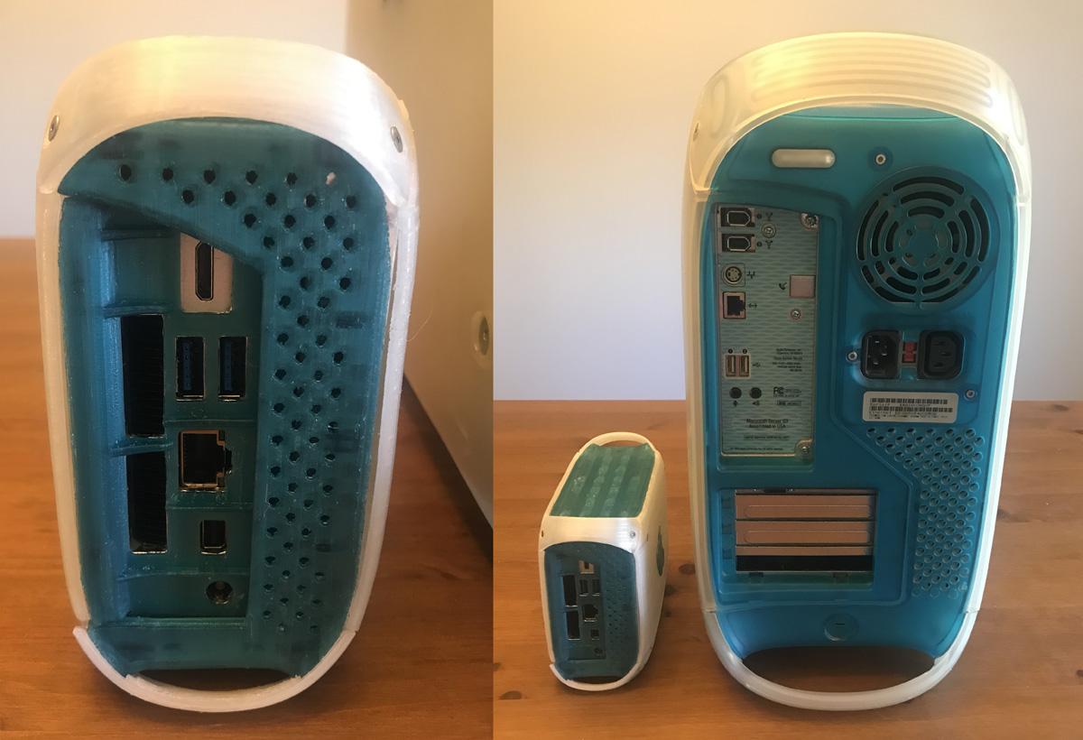


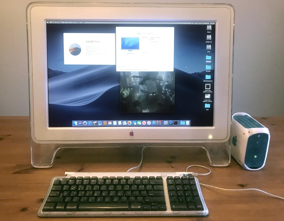
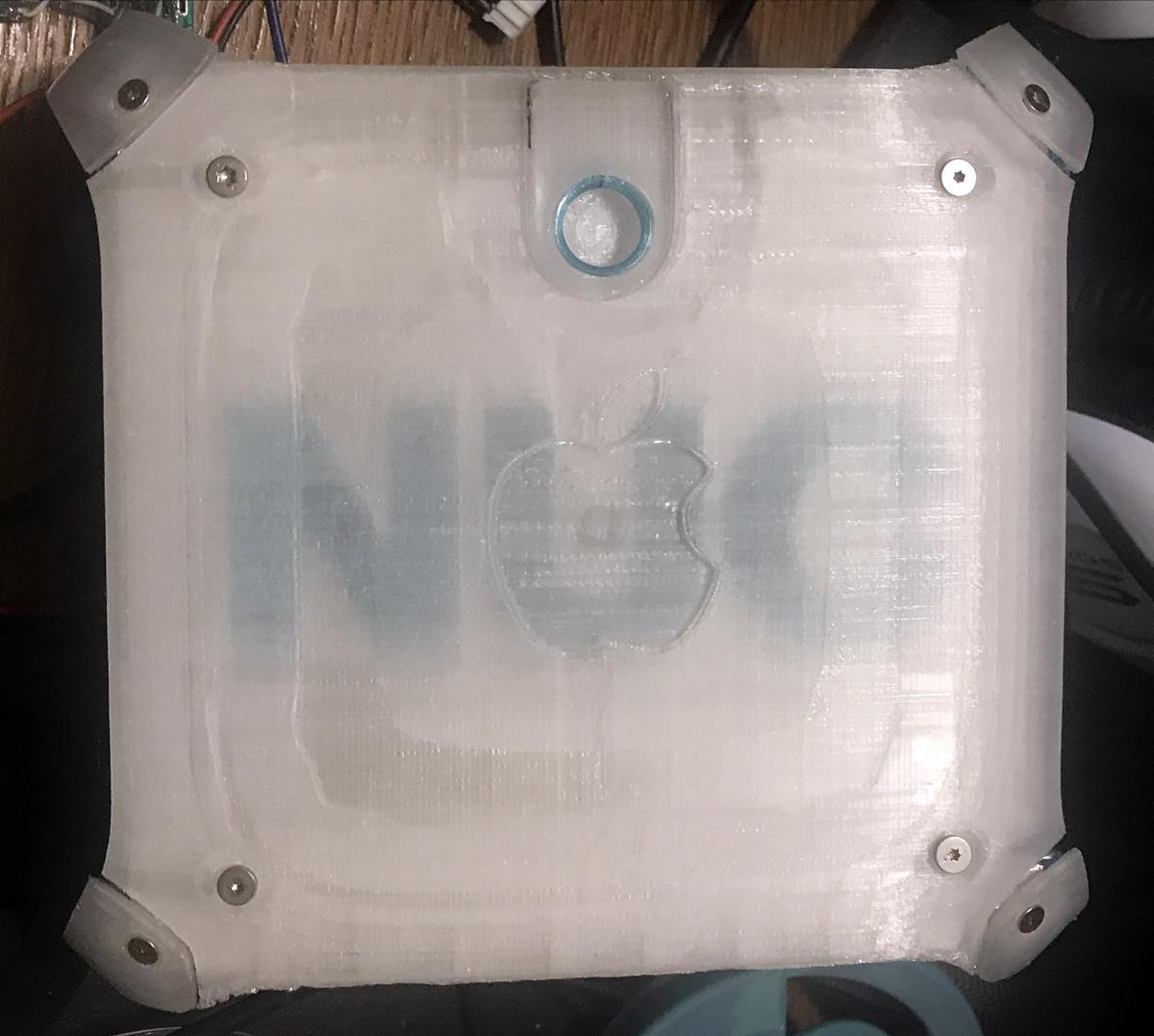
Creating a Hackintosh (MacOS on non-Apple hardware) is beyond the scope of this Instructable. There are many other resources out there to help you with that process. The Intel NUC has an application where you can change the BIOS boot logo, so I created a mashup of Apple and NUC for my boot logo.
Do you prefer the mini-screen or the 23" Cinema Display (last 2 photos)?
Enjoy your mini Powermac G3!