Mixing Table

This project was developed for 'Electrónica Creativa' (Creative Electronics), a Beng Electronic Engineering 4th year module at the University of Malaga, School of Telecommunication (http://etsit.uma.es/).
_______________________________________________________________________________________________
This desing has some errors!
If you want do the the project you have to change some things. During the explain the errors will be pointed out and explained in italics.
_______________________________________________________________________________________________
¿What are we going to do?
The idea of this project is to develop and build a mixing table with 2 mono input channels to which we can adjust the high and low frequencies, the volume and mix the 2 songs.
Downloads
Supplies
• Encapsulation:
- Box manufactured by 3D printing.
• Electronic components:
- 5 10k rotary potentiometers.
- 2 100k rotary potentiometers.
- 2 500k rotary potentiometers.
- 4 3.5 mm Jack connectors.
- 1 12V power supply.
- 1 PCB board designed and manufactured specifically for the project, with the electronic components detailed in the following Excel file.
- 40 Arduino connection cables (female-female).
- 3 male-male Jack cables.
- 11 4mm scrums.
• Additional equipment:
- Speakers.
- Headphones.
- Oscilloscope
- Function generator
Design and Simulate the Circuit in Orcad
The first stage of the circuit is a Baxandall filter that adjusts the frequency that passes through (in this case the Baxandall is only for high and low frequencies).
The second stage is a volume control that allows you to raise and lower the volume of each channel independently and you can also raise or lower the volume of the sound that goes to the audience or the sound that goes to the headphones that the DJ listens to, that is, from here there are 2 paths.
After that, on the public channel path is possible to control the output volume (with the two songs added together).
On the DJ channel path there are an amplifier circuit that amplifies the signal to make it possible to hear it through the headphones.
In this part we made a mistake (ERROR1) : The audio voltage is around 1V RMS but we don’t take into account that the Baxandall filter has a gain so the out voltage of the first stage is not 1V RMS, but it even reaches saturation at 12V (power supply voltage of the amplifiers).
To fix this error, an intermediate stage would have to be added to lower the voltage to line level.
Testing the Different Parts of the Circuit on a Proto-board
We recommend that you test the design on a proto board before designing and ordering the PCB to avoid possible errors.
Desing the PCB


These are the basic steps to make the PCB, but if you do not have experience we recommend taking a PCB design course.
- Installation and Setup (KiCad)
- Schematic Design
Open the schematic editor.
Add components using the Add Symbol tool.
Connect components with wires (W) and assign values/references.
Generate a BOM if needed.
In our PCB schematic desing there are an error (ERROR2), apart from ERROR1 obviously. The Q1 transistor that is in the block called “amplificador auriculares” is not correctly placed because the emisor and collector are exchanged.
- Assign Footprints
Open the footprint editor and assign footprints to components.
- Generate Netlist
Save and generate the netlist to link the schematic to the PCB.
- PCB Layout
Open the PCB editor and configure it for 2 layers.
Import the netlist to place components.
Arrange components and route tracks (X).
Add copper zones for ground (GND) and power (VCC).
Run the Design Rule Check (DRC) to ensure there are no errors.
- 3D Visualization
Use the 3D viewer to check the physical appearance of the PCB.
- Generate Gerber Files
Export Gerber files and drill files for manufacturing.
Verify the Gerbers using KiCad's built-in viewer.
Apart from these steps to follow, you have to take into account that the electronic components you are going to use are in stock at the PCB manufacturer if you are going to order it with the components already soldered like us. If, on the other hand, you decide to solder them yourself, you also have to take into account the supplier's stock.
Send the PCB to Be Manufactured
Upload Gerbers to a PCB manufacturer (e.g., JLCPCB, PCBWay). In our case we use JLCPCB.
Confirm specifications (thickness, color, etc.) and place your order.
Since we place the order with the components already soldered, we must also specify other parameters such as the list of components and their positioning. It is important to provide these parameters in the format required by the manufacturer.
Placement files
Components Files
Designing the Mixing Desk Box Using 3D


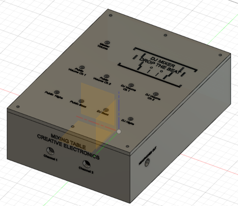
The design was made in fusion360 and has 2 bodies, the box and the lid. It was then laminated using PrusaSlicer and printed on the UMA 3D printer.
Downloads
Wait the PCB ;)

Hardware Implementation

When the PCB arrived we made all the potentiometer connections in place and also fed the circuit with +-12v. First we tested the circuit with the function generator instead of an audio signal. That was when we noticed ERROR1 since the oscilloscope showed it saturating.
Also after a few tests one of the transistors in the headphone amplifier circuit burned (ERROR2).
So we cancelled that stage so we could continue testing the rest of the circuit. Finally we dared to use an audio signal and connect a speaker to the "BALANCE_publico" output and although the audio quality could be improved it worked, we had a signal at the output and when moving the potentiometers there were variations in the sound!