Remote Control Racing Car With Camera Feed Using Mobile Phone
by be1jd in Circuits > Remote Control
205 Views, 3 Favorites, 0 Comments
Remote Control Racing Car With Camera Feed Using Mobile Phone
Build your own smartphone controlled FPV RC Car with live video streaming. No app required. Just connect to WiFi and Drive from your browser.
It has video game-like controls, real time control ( 5 to 50 mili-second ) & live video feed. The web controller is stored inside the ESP32 itself.
The Car creates its own Wifi Network and by connecting to wifi you can open the Remote Controller from the browser.
It uses Websocket connection on top of HTTP for Low Latency Connection over Wifi.
If you want to see Actual Demo of Web_Controller from your Phone checkout https://be1jd.github.io/ website.
Key features :
- Wifi Control using any Phone or PC.
- Live Video Feed.
- Real-Time Controls over Websocket
- Live Telemetry.
Time Required :
- Hardware : 5-8 Hours
- Software : 20 Minutes
Estimated Cost :
- $30-45 USD
- 1500-2000 INR
Supplies
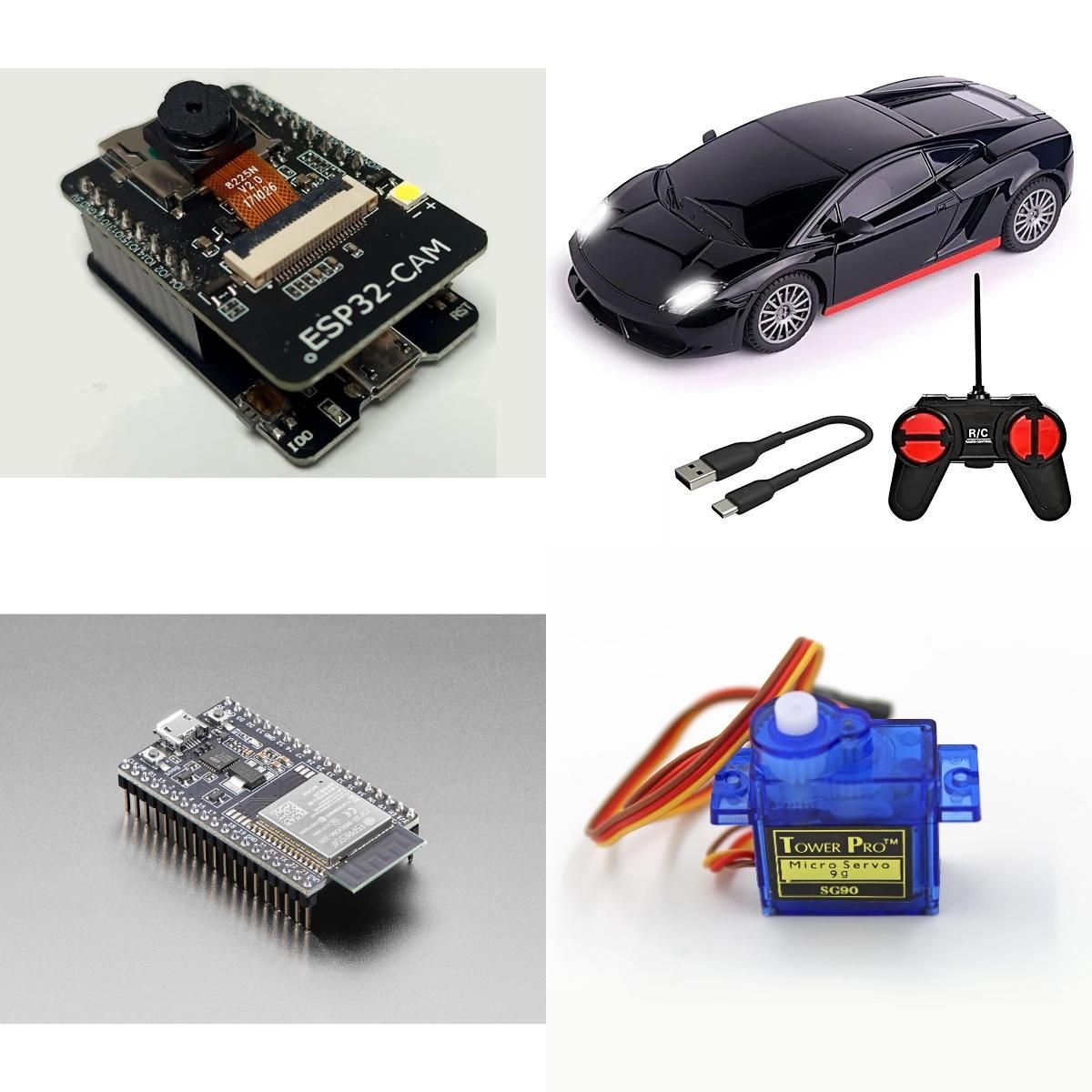
- ESP32-CAM AI Thinker - 1
- Toy RC Car Chassis - 1
- ESP32 Dev Board - 1
- SG90 Servo Motor - 1
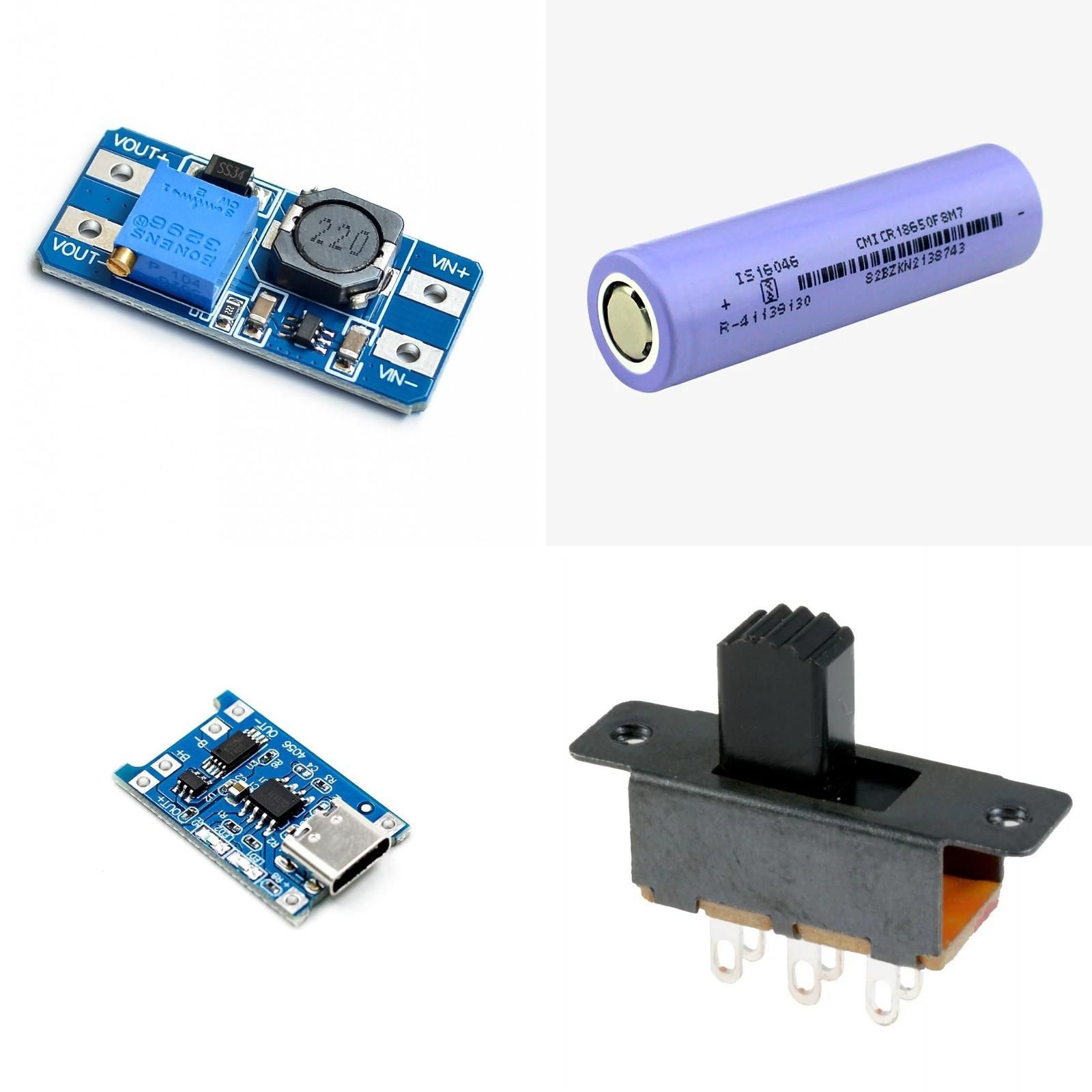
- 5v Boost Converter - 1
- 3.7v Li-ion Battery - 1
- Charging Module - 1
- Power Switch - 1
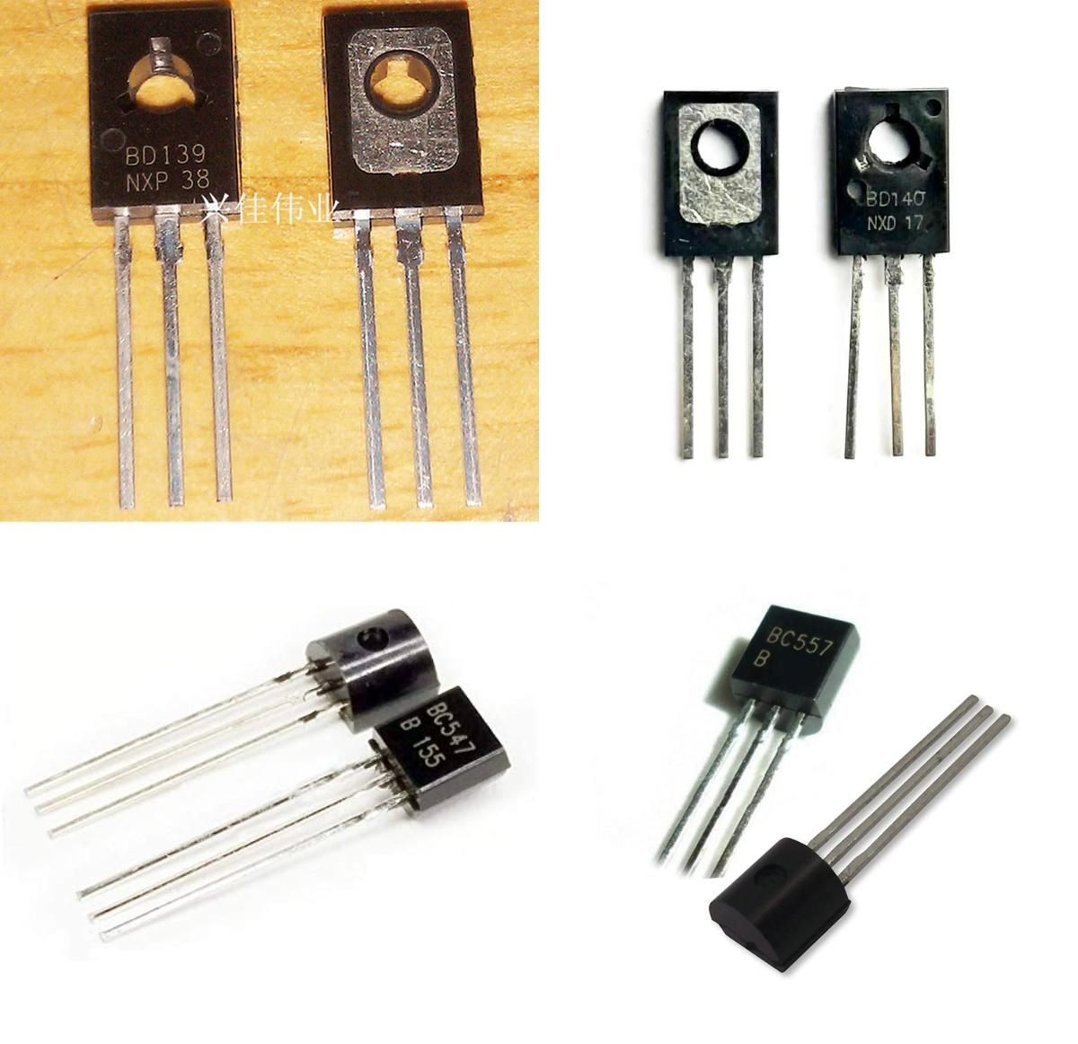
- BD139 Transistor - 2
- BD140 Transistor - 2
- BC547 Transistor - 2
- BC557 Transistor - 2
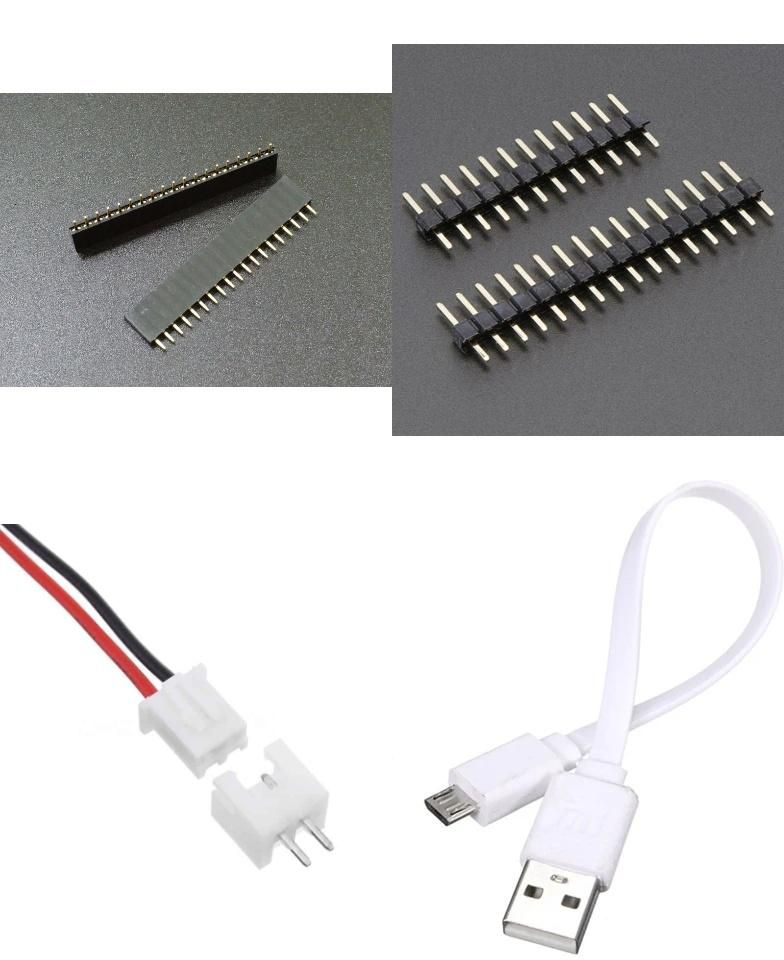
- 60 Female Header Pins - 1
- 60 Male Header Pins - 1
- JST Connector (Male & Female) - 1
- USB Data Cable for programming - 1
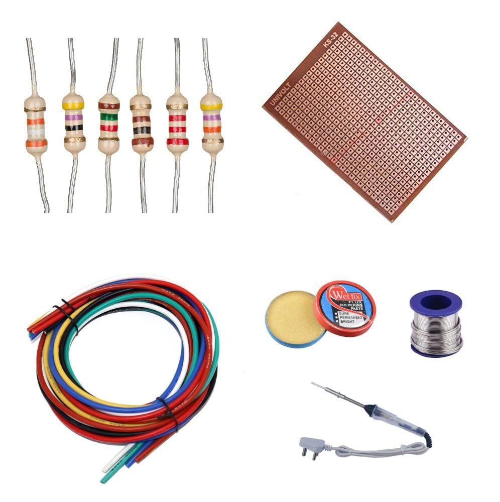
- 33 ohm Resistor - 4
- 1k ohm Resistor - 4
- 470 ohm Resistor - 2
- 22k ohm Resistor - 1
- 15k ohm Resistor - 1
- General Purpose PCB - 1
- Single Strand Wires
- Soldering Iron, Soldering Wire & flux
Remove Cover
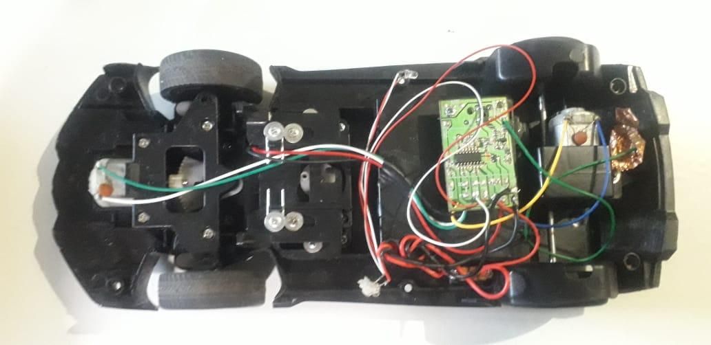
Remove the four screws from the bottom of the RC car keeping the top plastic cover in place, and put the screws aside for later reassembly.
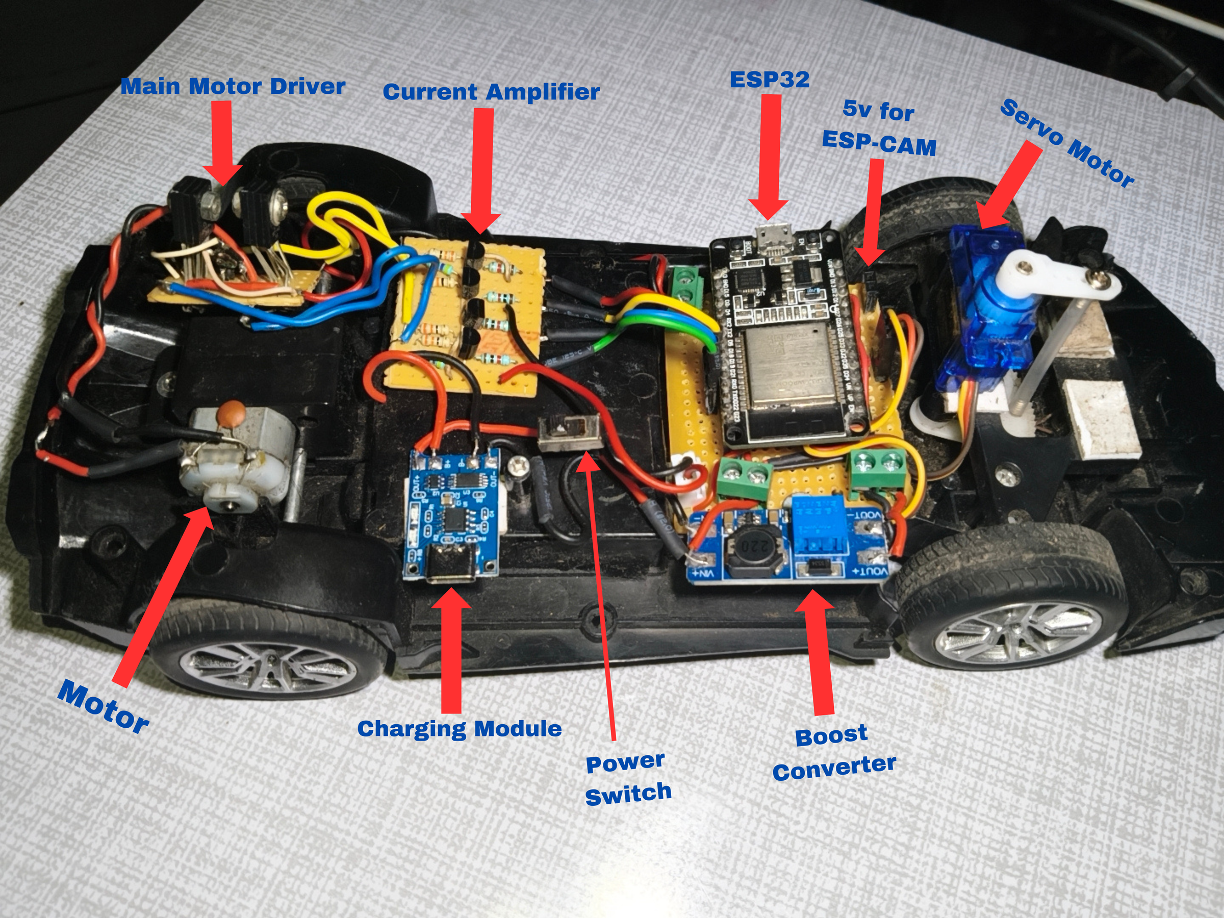
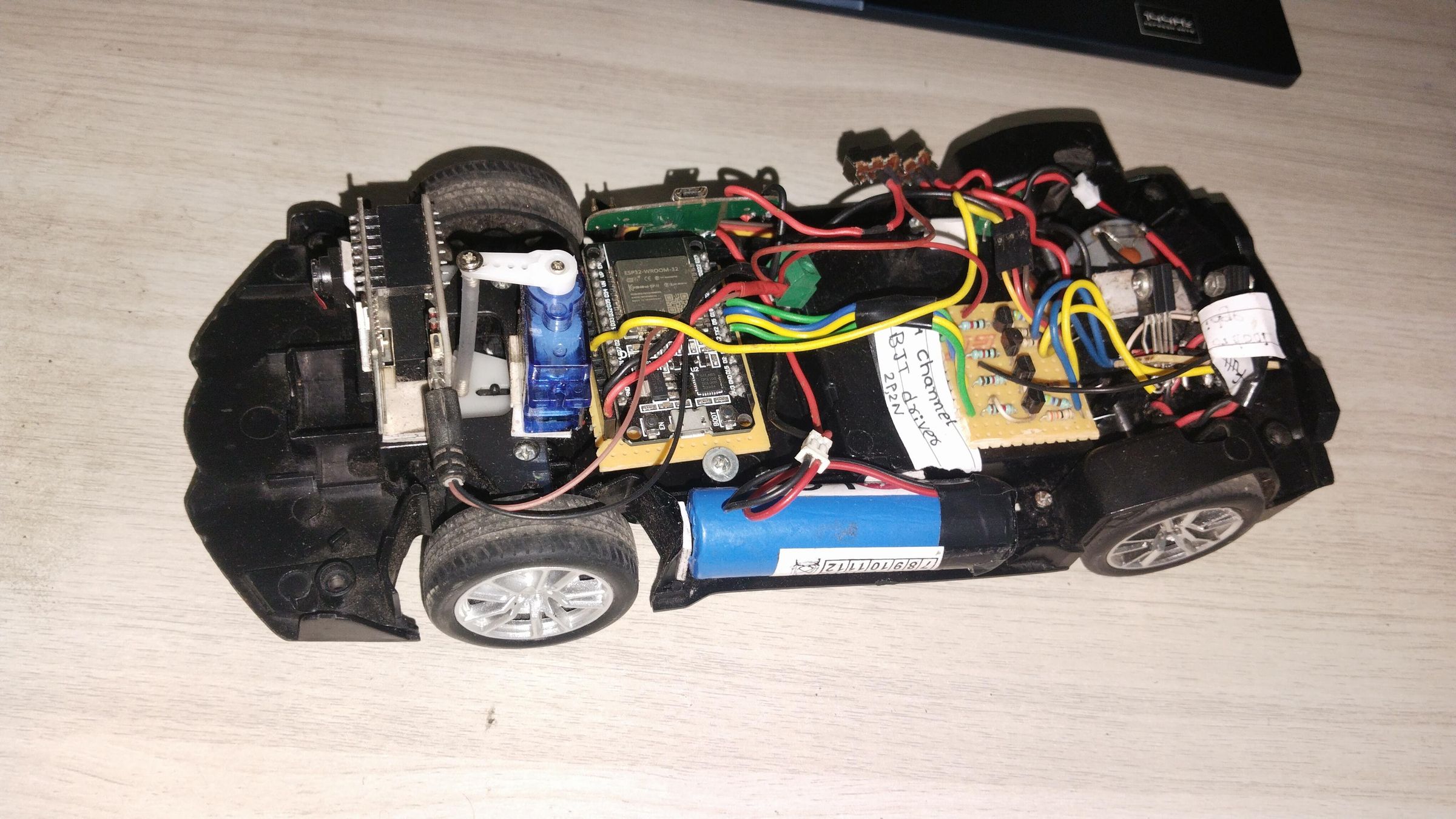
Remove the top cover. You will be exposed to the Inner electronics of the car as shown in the image.
Remove the Electronics
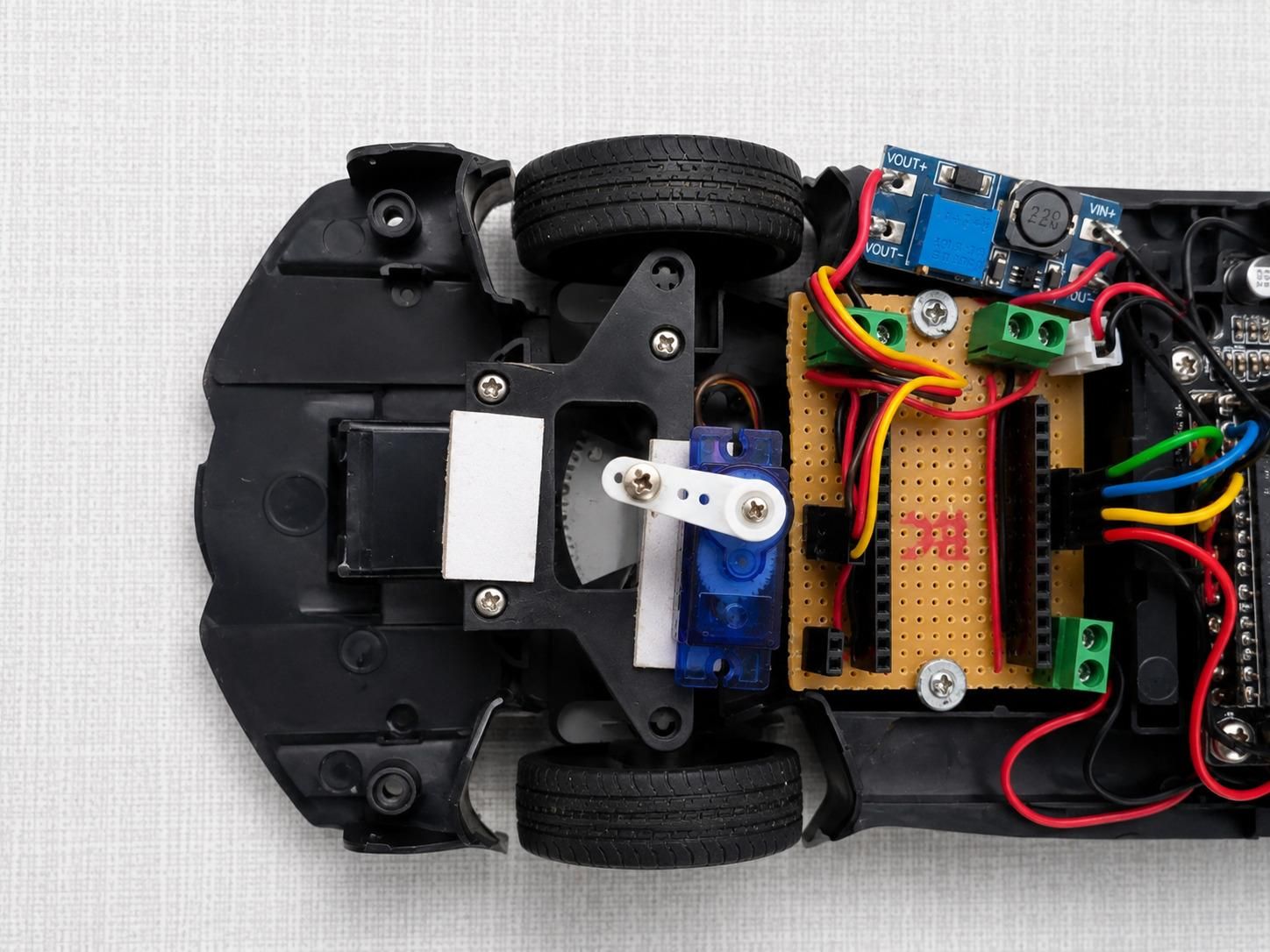
Remove the Steering dc motor if you have them because It consumes a lot of Power for Steering and Drain Battery Fast.
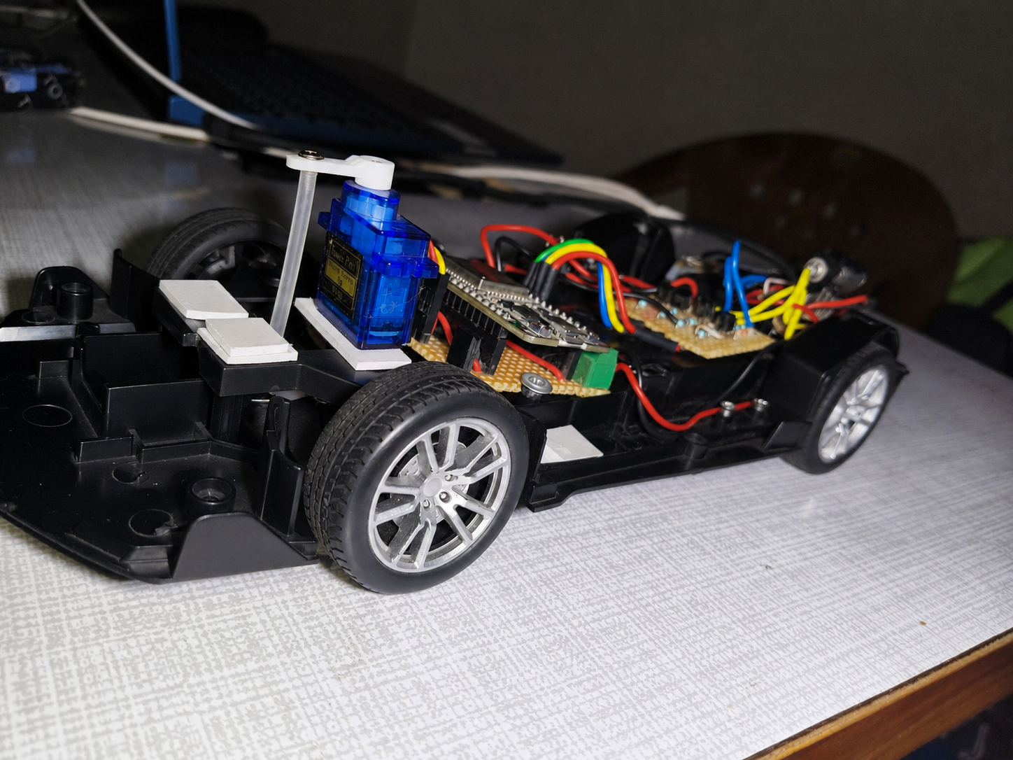
After Removing steering motor Place Servo motor Such that its rotating shaft center matches the wheels rotating gear center.
Fix the servo in place with two side taps and Check by changing its angles using arduino or leave it for now as we are going to check it later using main esp32.
Making Main PCB Board
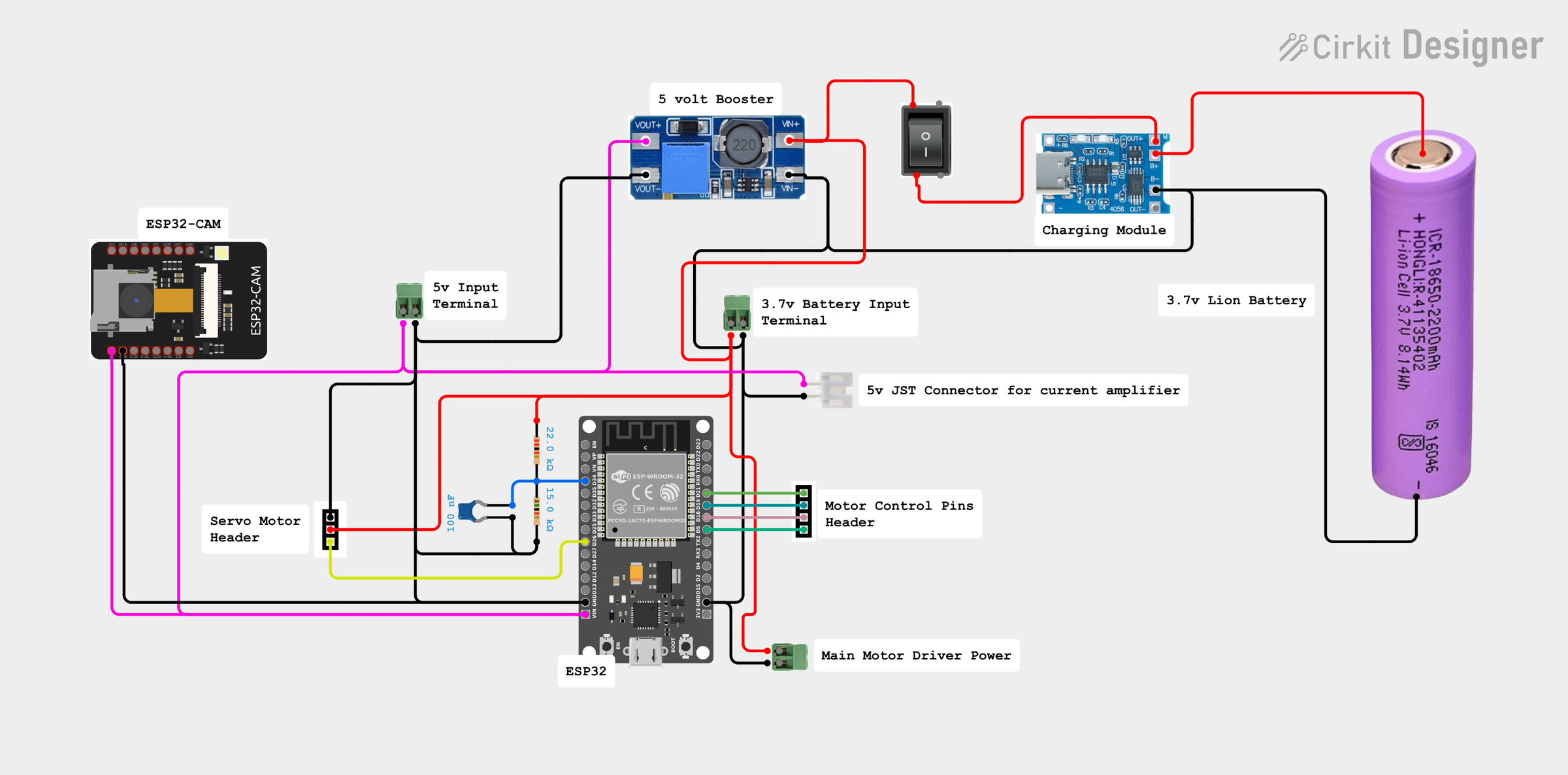
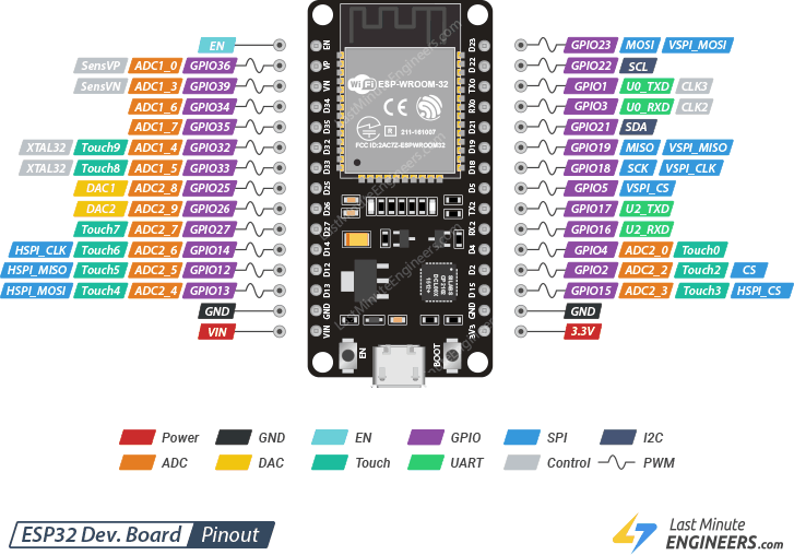
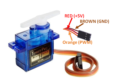
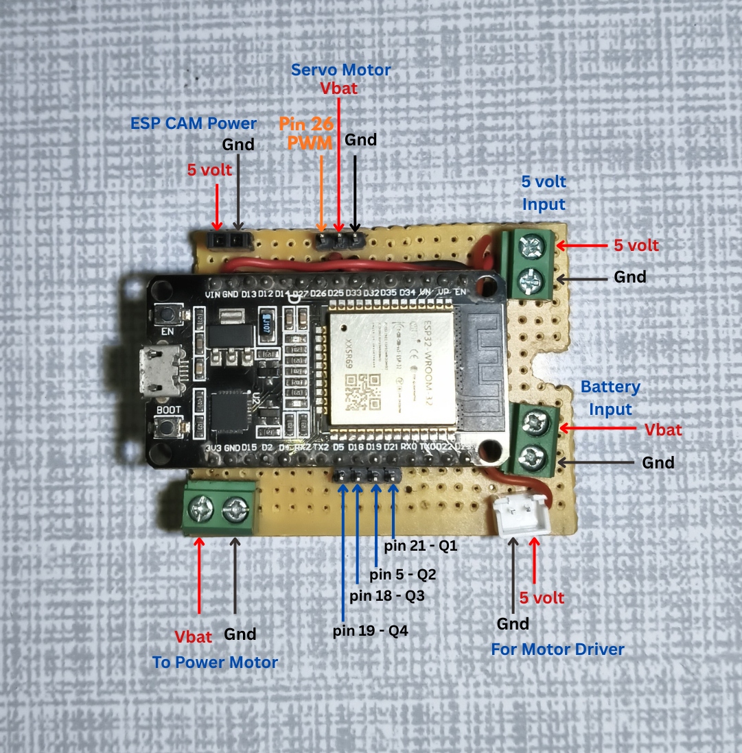
I am making a Modular PCB but you can connect these things directly with esp32 if you want to. Just that the modular PCB is more convenient for later customization and upgradability.
Cut General PCB Board such that it can easily be fitted on the Car body. Once you cut the appropriate part then start placing the components & connectors as per the Block diagram of Main PCB.
Connectors and their purpose :
- 3 Male Header Pins for Servo Motor
- 4 Male Header Pins for Rear Motor
- 1 Screw Terminal for 5v Power input
- 1 Screw Terminal for 3.7v Battery Input
- 1 Screw Terminal for Motor Driver
- 1 JST connector for Current amplifier
- 2 Header Pins for Powering ESP32-CAM
- 1 Power Switch
ESP Pinouts for Reference :
Pin 26 :- Servo Motor PWM Pin
Pin 19 :- Q1 : BD140 (PNP) transistor for backward direction
Pin 18 :- Q2 : BD140 (PNP) transistor for forward direction
Pin 5 :- Q3 : BD139 (NPN) transistor for forward direction
Pin 21 :- Q4 : BD139 (NPN) transistor for backward direction
Pin 34 :- Battery Voltage Monitoring(Optional).
Steps :
- First Solder Two parallel 40 pin Female Header for ESP32 & then Place ESP32 for correct pin referencing of other components.
- Place the 3 Male Header Pins for Servo motor on PCB such that Servo’s PWM pin aligns with ESP32 Steer Out Pin ( GPIO 26 ). Solder Header Pin in place.
- Now take 4 Male Header pins for Rear Motor control and place them parallely to the GPIO 19, 18, 5 & 21. Also solder them in place.
- Now Solder all three Screw Terminals as shown in the Main PCB reference Image for 5v Input, Battery input & Motor Driver Power. you can place them as per your convenience.
- Also Solder one JST Connector with 5v power to power current amplifier and another one for Powering ESP CAM & If you’re not using ESP CAM then you can skip this step.
- Take 22k and 15k ohm resistors, put 15k resistors one terminal to the ground and 22k resistor’s one terminal to the battery input. Place a 104(1uF) capacitor in parallel with a 15k resistor. Connect the center tap to PIn 34 on the ESP-32.
- Connect everything by taking reference from the Main PCM circuit diagram.
- You can Place Switch on the PCB or Extend it through Wire up to your choice. I have used it between the Charging Module Output & Volt booster.
- Now Take Single Strand Wires and connect components with the Help of Circuit Diagram.
- After soldering Connect Battery and Check if the ESP 32 is powering up.
Making Custom Motor Driver
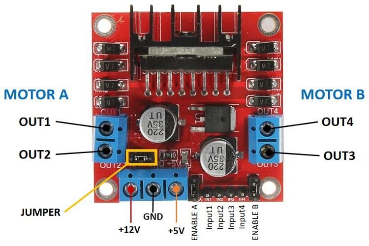
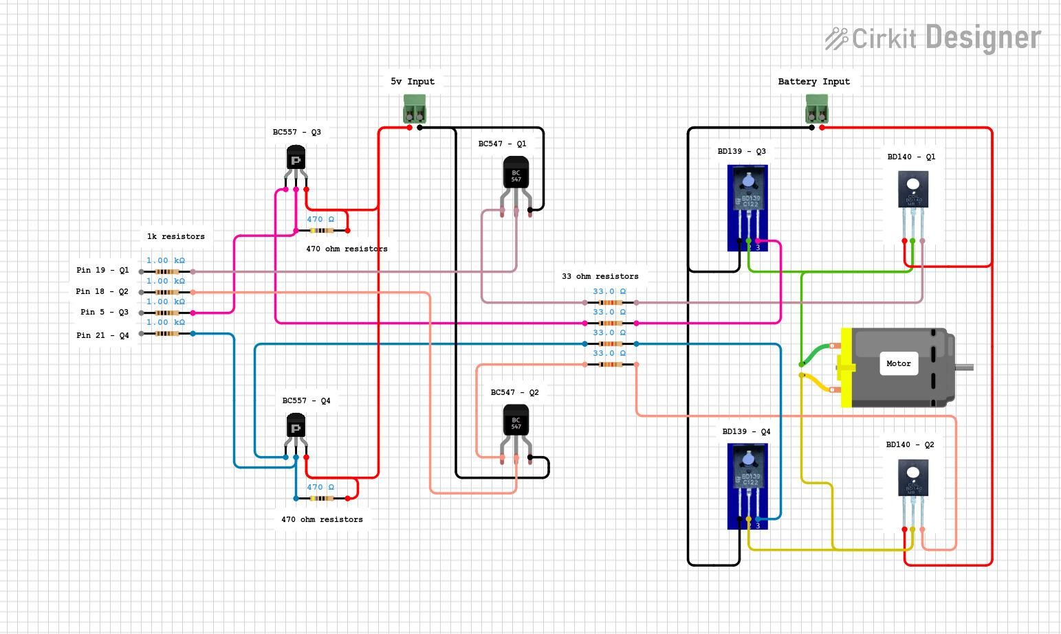


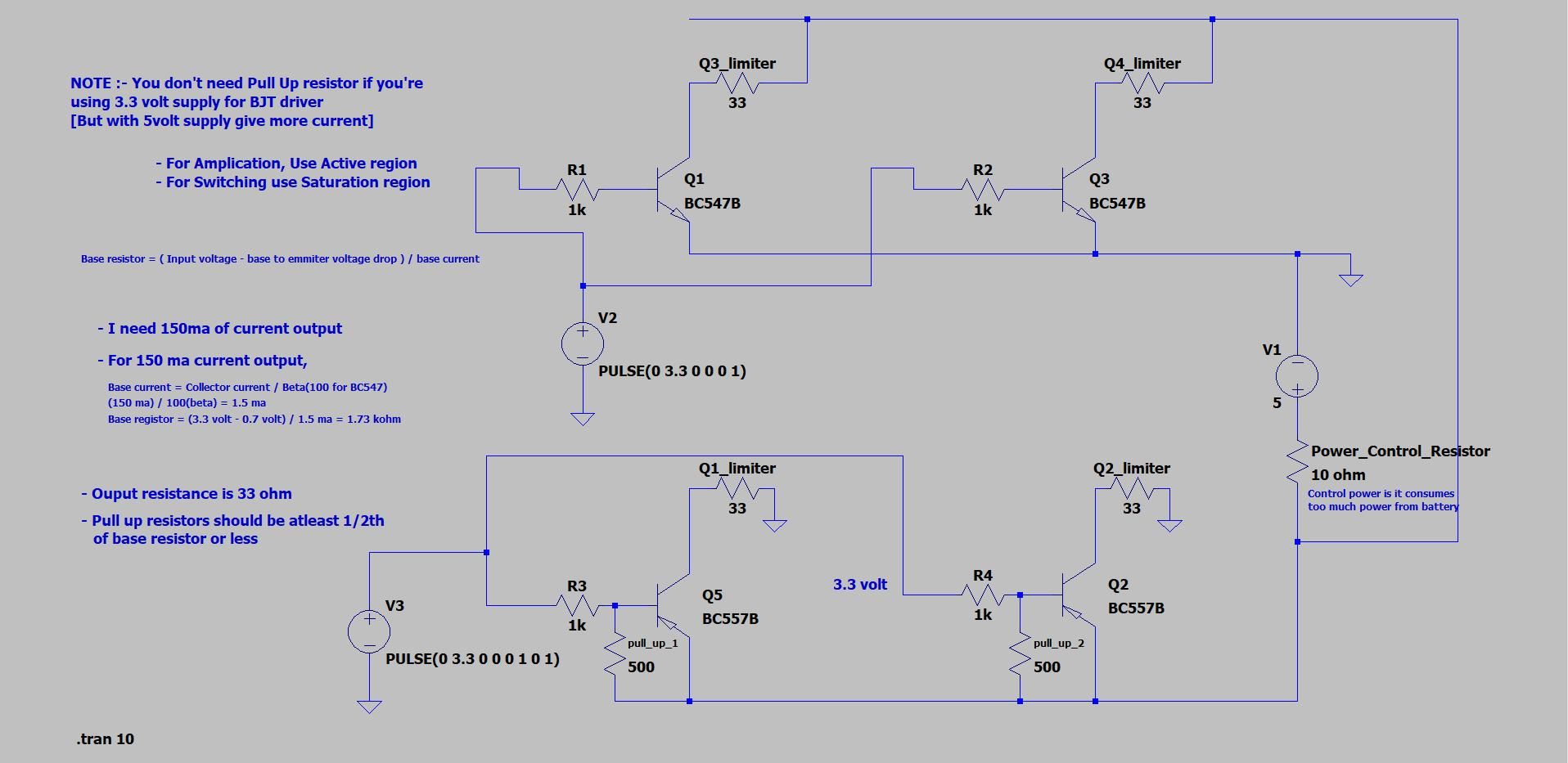
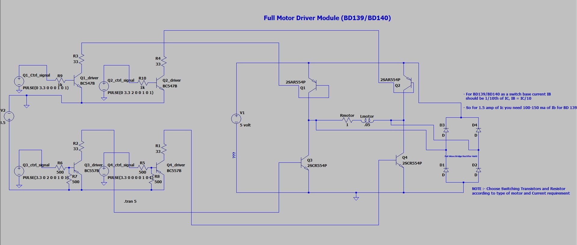
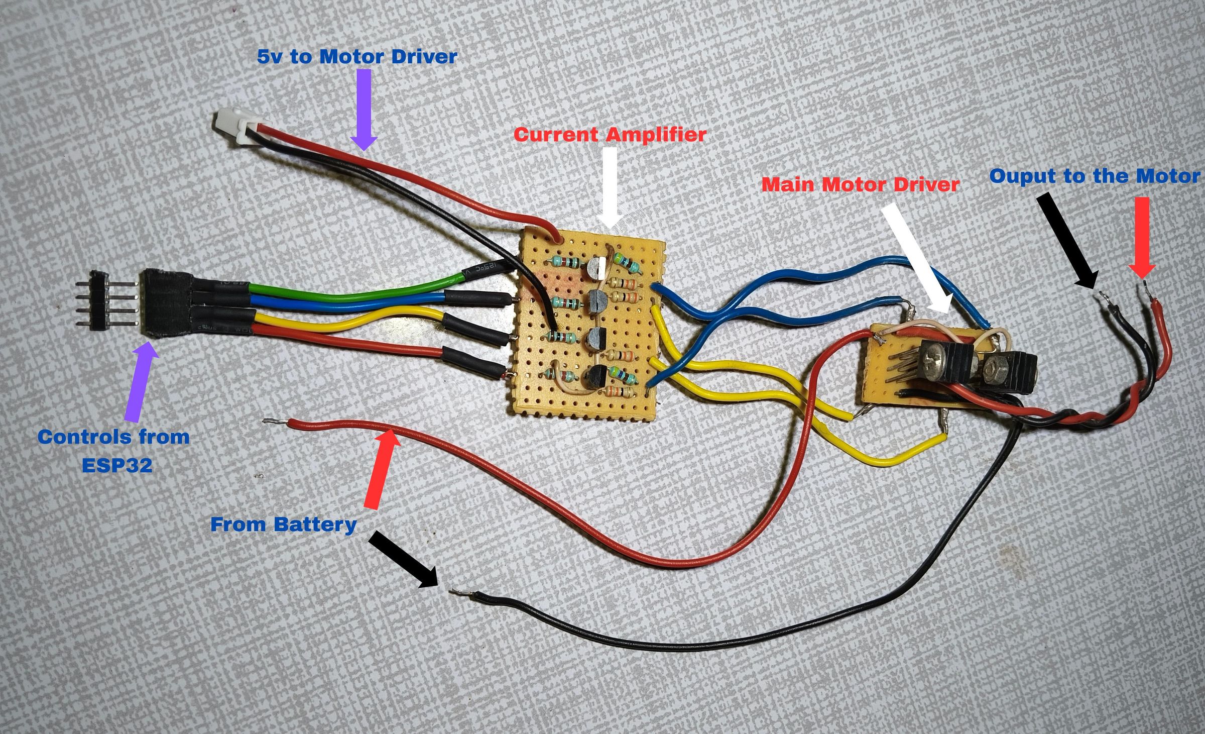
If you are using a ready made Motor Driver module You can Ignore this step and directly connect the motor driver using the pinout diagram shown above.
Take a small PCB & Place two BD139 NPN transistors and two BD140 PNP transistors & Solder Them on PCB as shown in the reference Image. Both BD139 and BD140 have the same Pinouts. Correct Pin Polarity is Important.
Once you are confident about Transistor Placement, Solder them in place and interconnect them according to the Circuit Diagram. You can Use Screw Terminals for Connecting Motor if You want.
Now take another small piece of small PCB & Place the BC547 & BC557 Transistors by following the Circuit Diagram. Also the Pinout for BC547 & BC557 are the same. Once Placing the Transistors Place Its time to Place resistors.
Put the 33 ohm resistor in series with all the pins going from the current Amplifier to the Main Motor Driver and Put 1k ohm resistor in series with all the pins that are coming from esp32 to motor driver.
It's important to place correct value resistors otherwise your esp32 or other components may damage so double check the values and connections.
Connect Everything Together
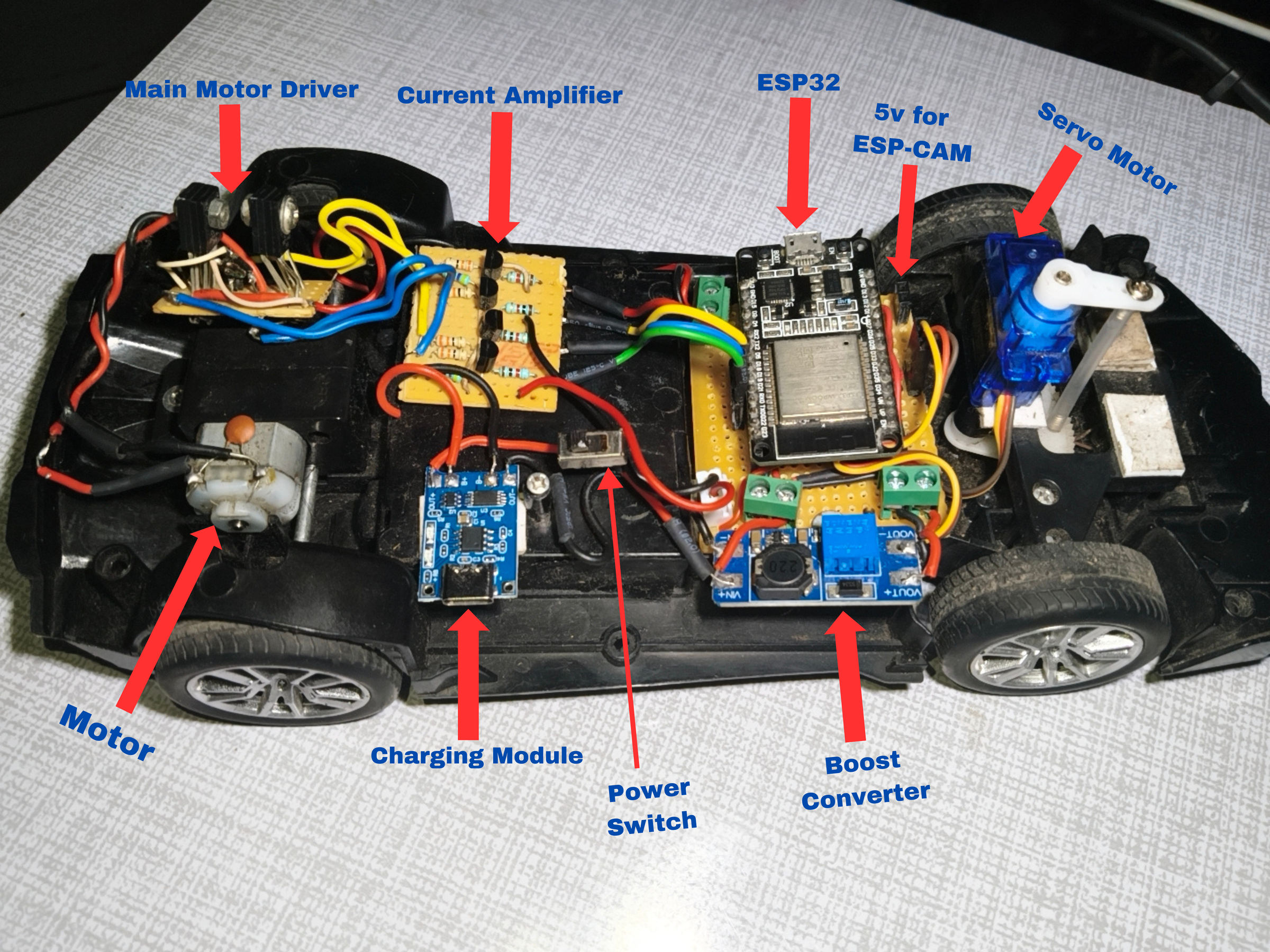
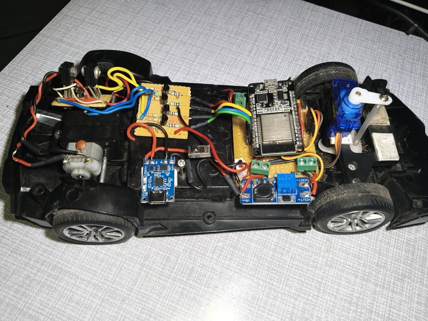
You can use Jumper Wire or directly solder Female Header pins for Motor driver connection. Make sure that the correct pins are connected to the correct Transistors.
Now Connect the Servo Motor Pins. Turn on the Main Switch and check if everything is working as intended.
The first thing to set before connecting everything is to set the voltage booster to 5v. Connect the voltage booster to its screw terminal.
Connect the servo pin to its header pins. Make sure you follow the pinout and color scheme of the servo motor.
Connect ESP-CAM to its header pin or JST connector to make sure that the ground and positive supply is not flipped.
Now for the Main motor driver make sure you connect it to the screw terminal that is directly connected to the battery positive.
After the motor driver you should connect the power JST plug of the current amplifier to its JST connector.
You can use Jumper Wire or directly solder Female Header pins for Motor driver connection as I have done in my case. Make sure that the correct control pins are connected to the correct Transistors.
Double check if everything is connected correctly according to the Images showing the interconnections.
Turn on the Main Switch and check if the main esp32 and the esp-cam is powering up and red light on both turns on.
Setting Up the Software
Install Arduino IDE if you don't have it already.
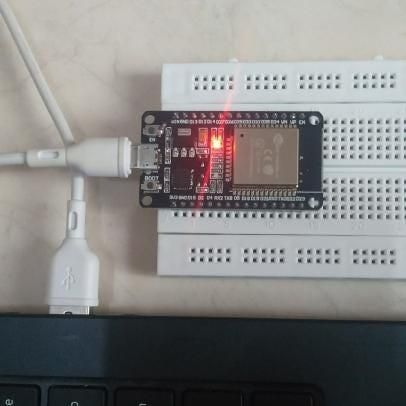
Connect ESP32 Dev Board with the PC using Micro USB cable.
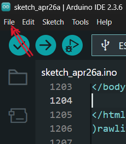
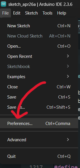
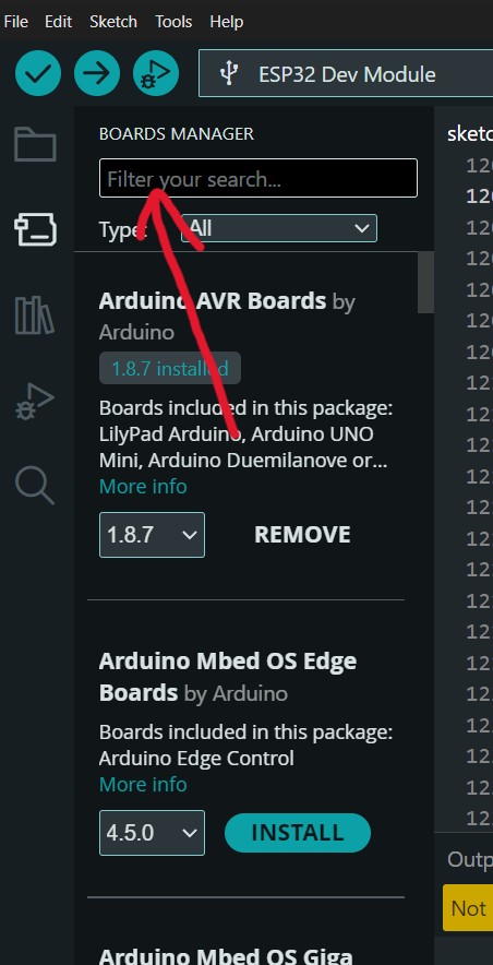
Add ESP32 Board in ESP32 by going into
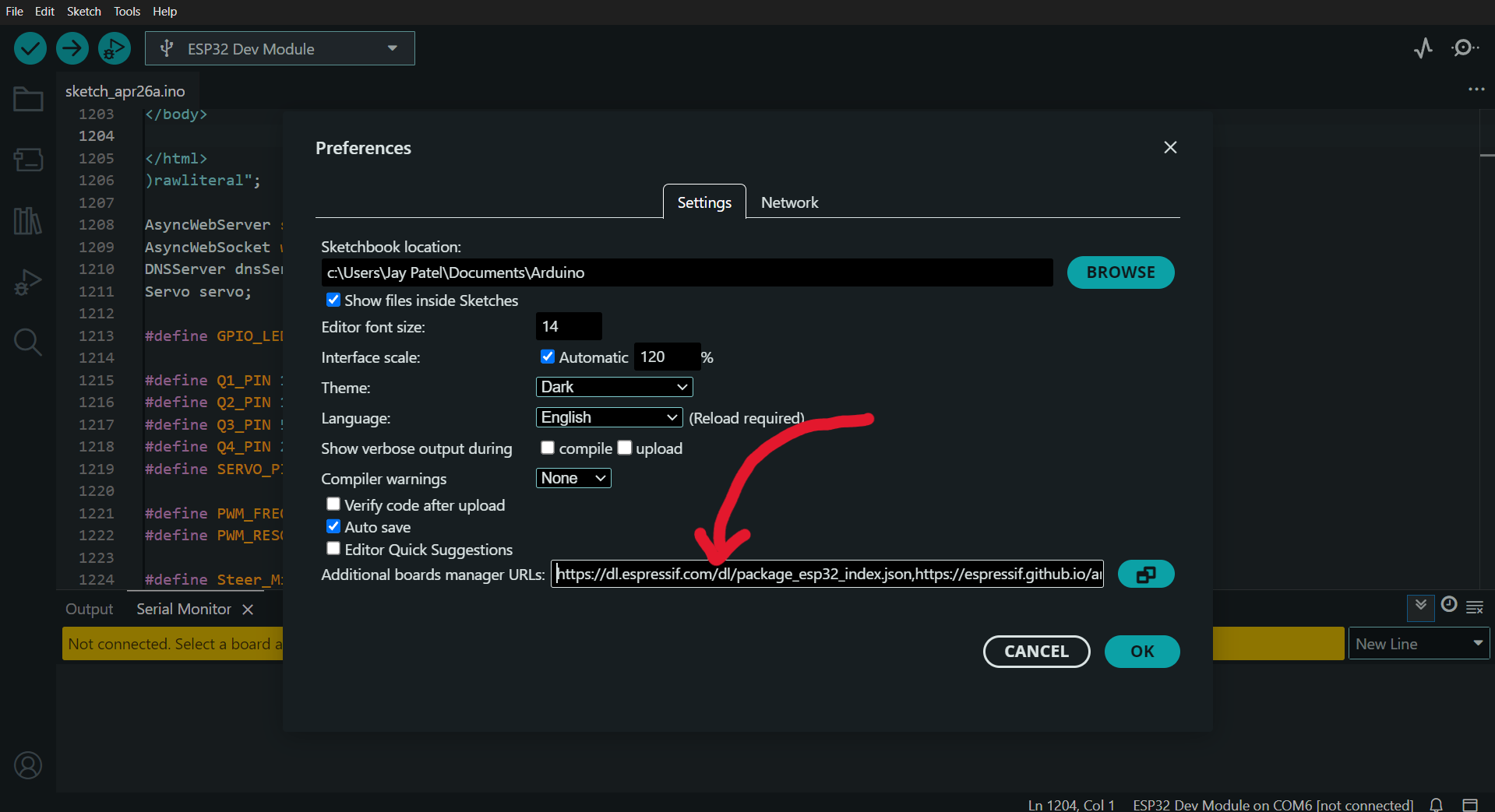
File -> Preferences -> Additional Board Manager URLs Paste following
Add the following URL here : “https://raw.githubusercontent.com/espressif/arduino-esp32/gh-pages/package_esp32_index.json”
Then Click "Ok".
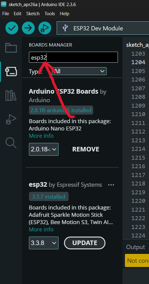
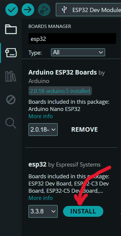
Now Add Board support Tools -> Board -> Boards Manager, Search for esp32 and install esp32 by Espressif Systems & Install It.
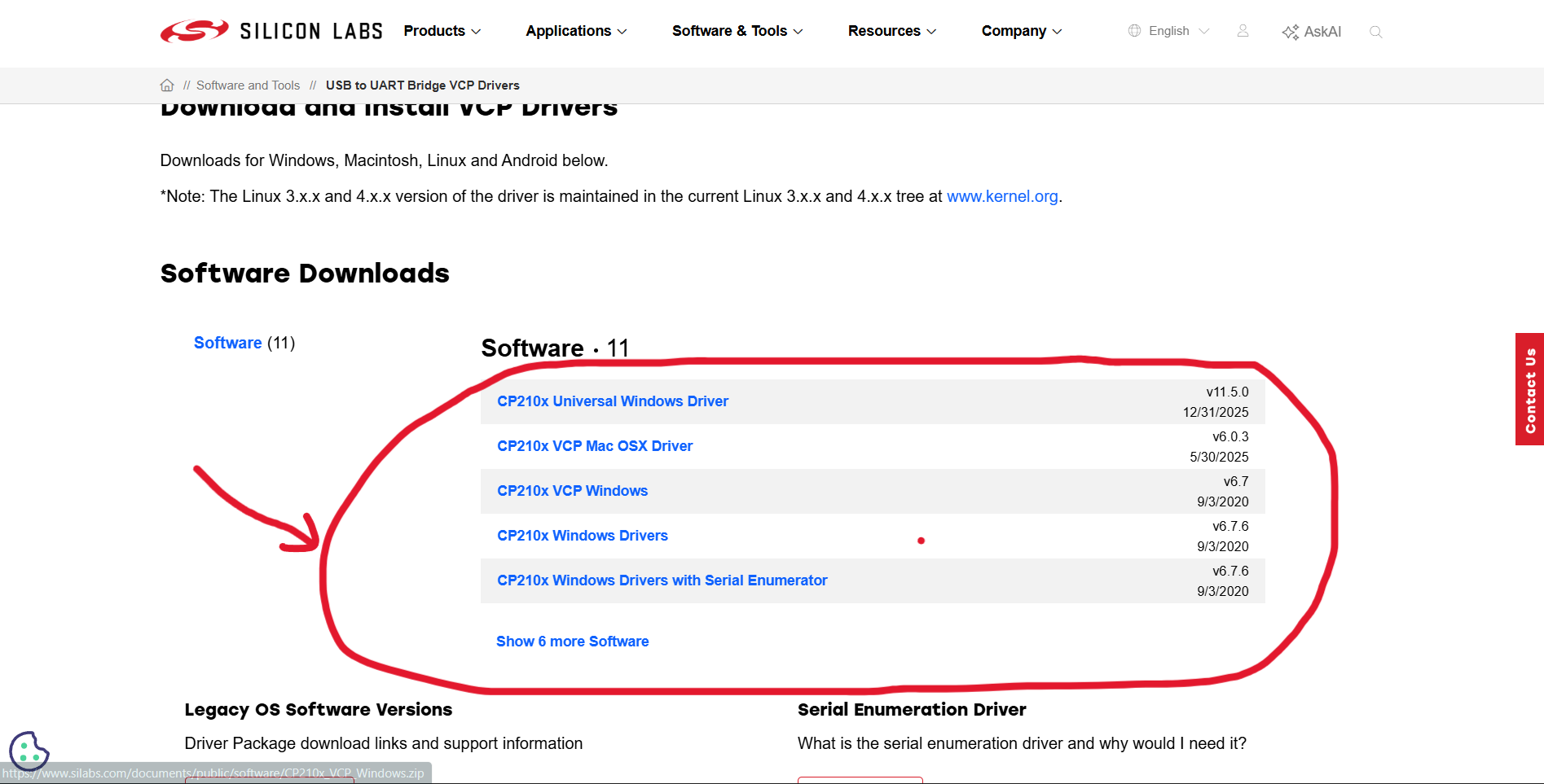
Install CP210x Driver from the Internet.
https://www.silabs.com/software-and-tools/usb-to-uart-bridge-vcp-drivers?tab=downloads
If this Driver doesn't Work Install CP340 Driver.
https://sparks.gogo.co.nz/ch340.html? srsltid=AfmBOoqFrgVHV3i_JpFbHGfBbBkL_CMcwzBjEJOwl8L5Ie6VV0qmCTNt
Download Zip file -> Extract file -> Run Setup -> Install it.
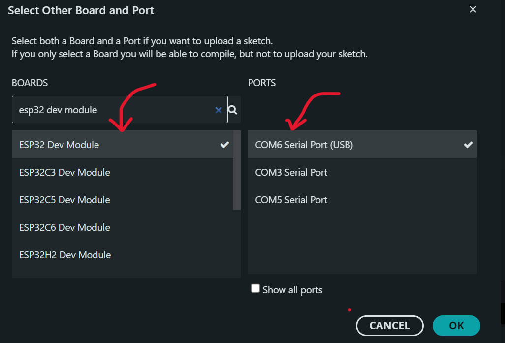
Now Open Arduino IDE and select Board as ESP32 Dev Module. Select available COM ports and check if any ports show connected status.
Upload Code into the ESP32 Board.
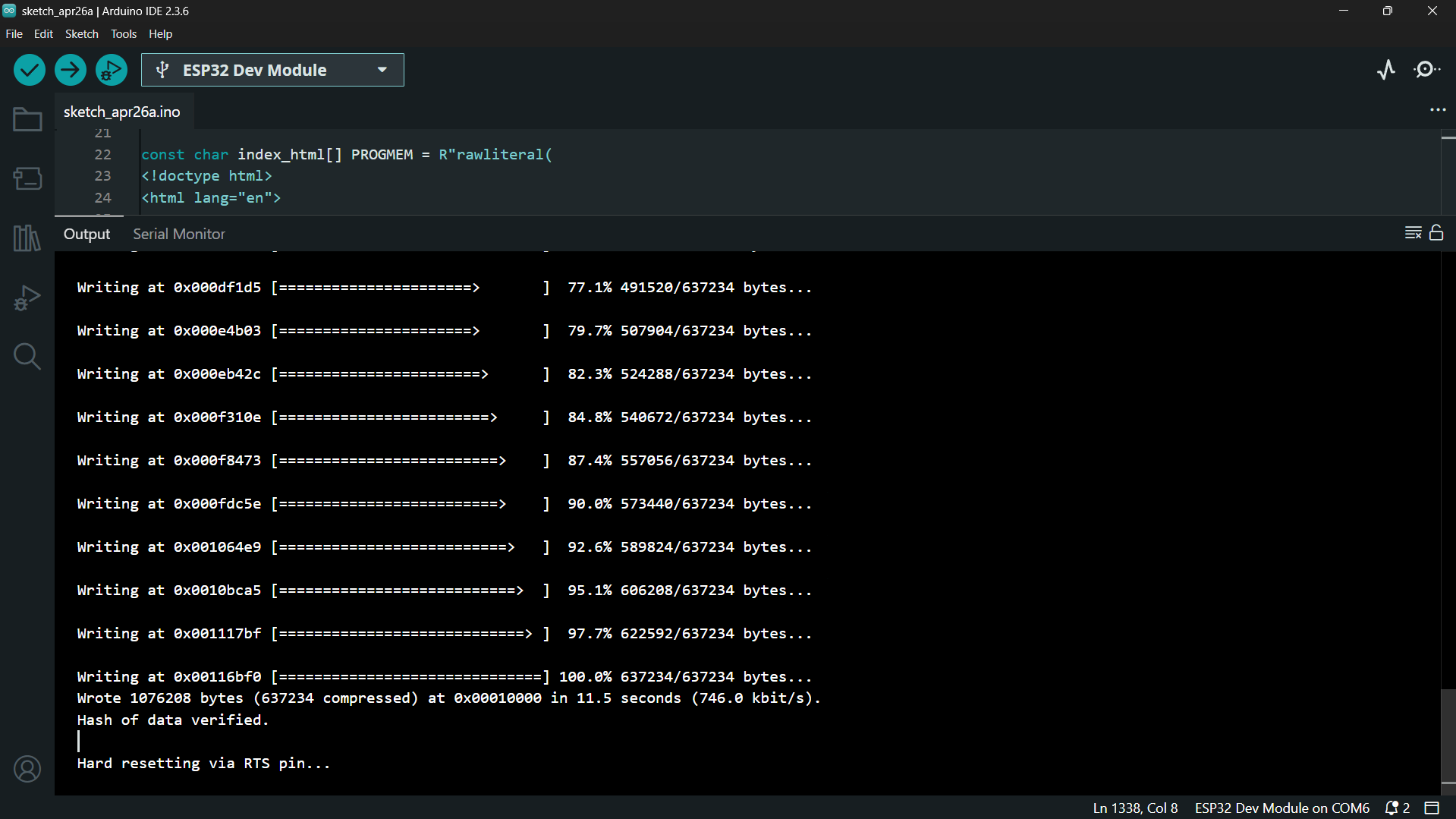
Wait for : Hard resetting via RTS pin...
Once You see it the Code is Uploaded Successfully.
Programming the ESP32
In order to Download Software Search for https://be1jd.github.io/#/project/fpv_car/code webpage.
Here You can also preview what the Web Controller will look like in your Mobile phone by Clicking on the Open Demo button.
Copy the code from the website and paste it in the Arduino IDE.
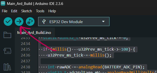
After Pasting the Code Hit Upload Button. This may take 5 to 10 minutes of time to compile and upload the code.
Once the Code is uploaded successfully you should see a message like Hard resetting via RTS pin…
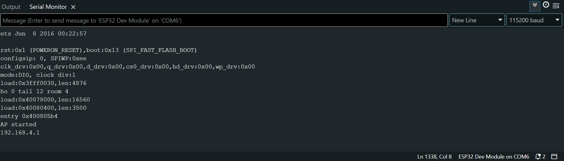
Now press Ctrl+Shift+M ( Serial Monitor shortcut ) to open Serial Monitor and reconnect the esp32 board to the computer. You should see the IP and other Logs as shown in the Image.
Connecting to Car’s Wifi
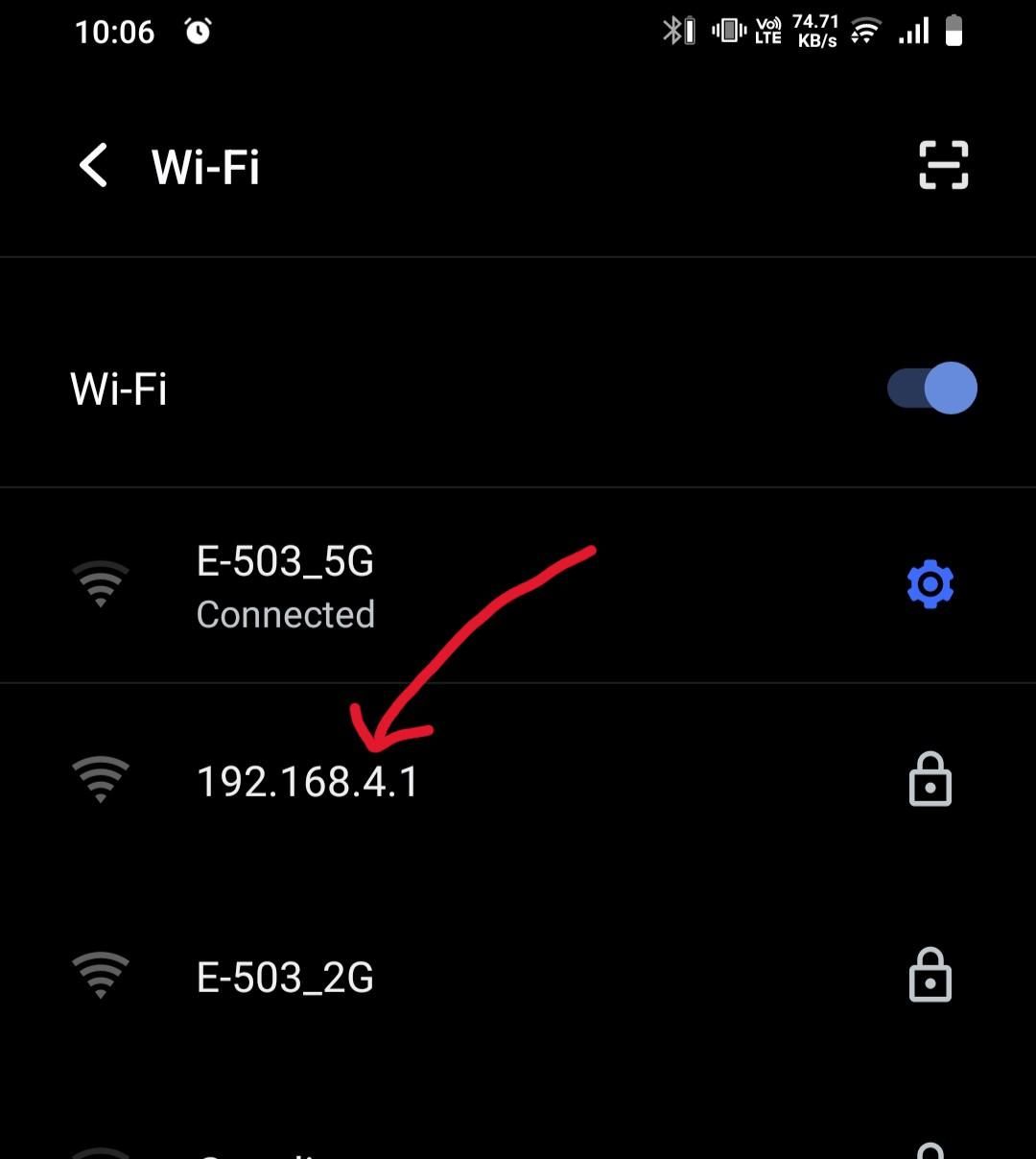
Turn On wifi and Open Wifi Settings. You should see 192.168.4.1 as your Wifi Connect to it with the Password 12345678.
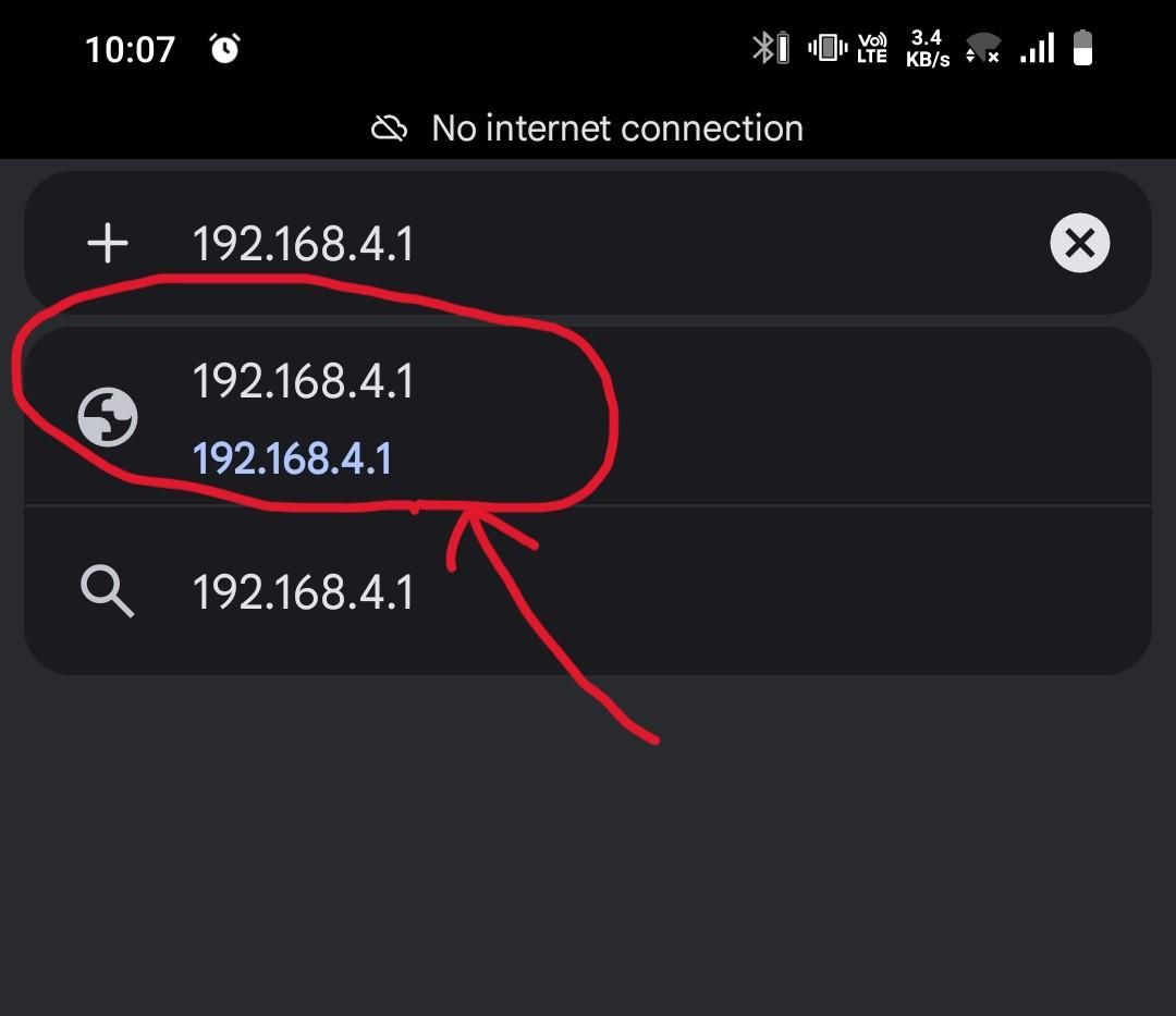
Once the Wifi is connected successfully Open Your Browser and Search for 192.168.4.1.
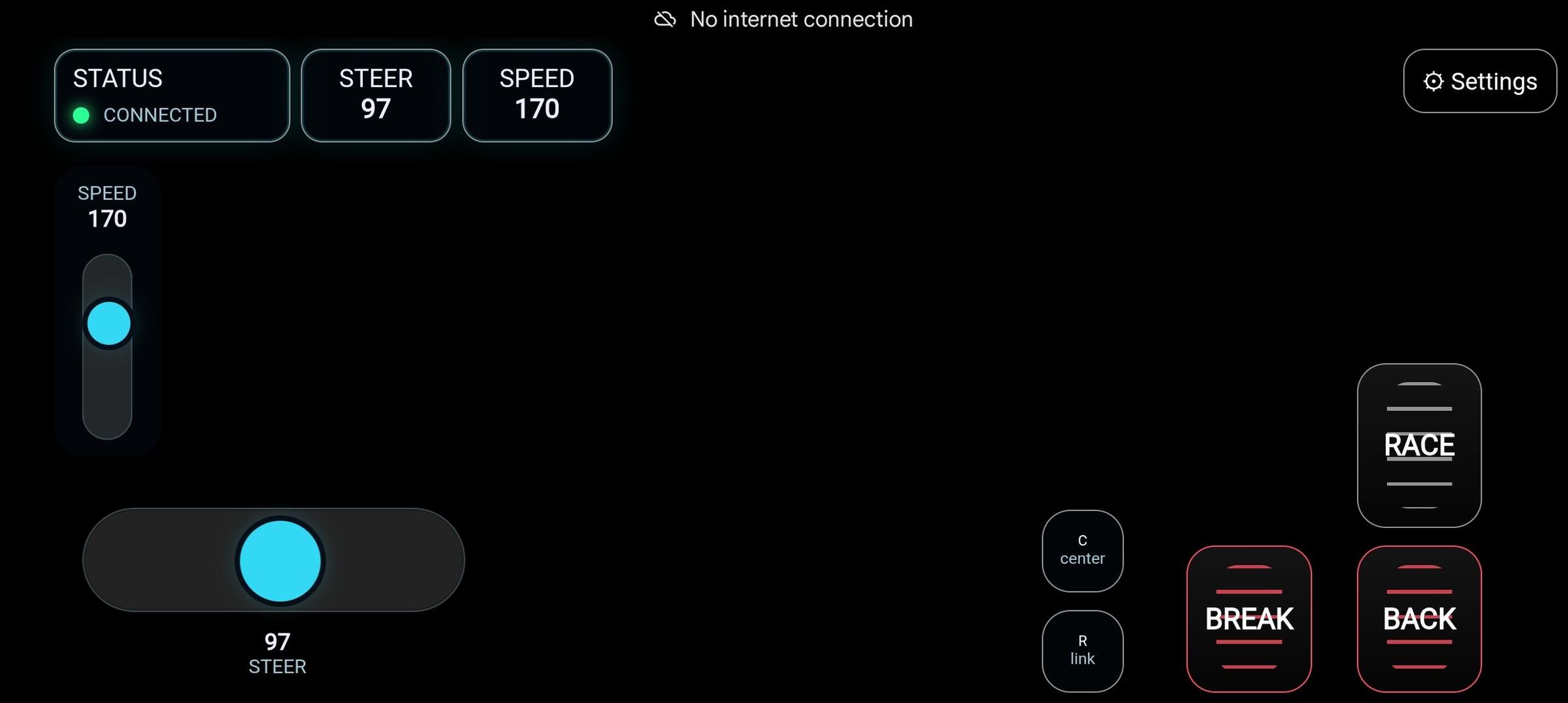
If you see The Status on the Upper Left corner is green and say connected means you are connected to a car. And if you don’t see Connected Try turning off your Internet and only connected to Car’s wifi.
Upper Left Corner -> Status -> Green Light -> Connected.
Status -> Red Light or yellow light -> Turn of mobile Internet.
Hardware Check Mode
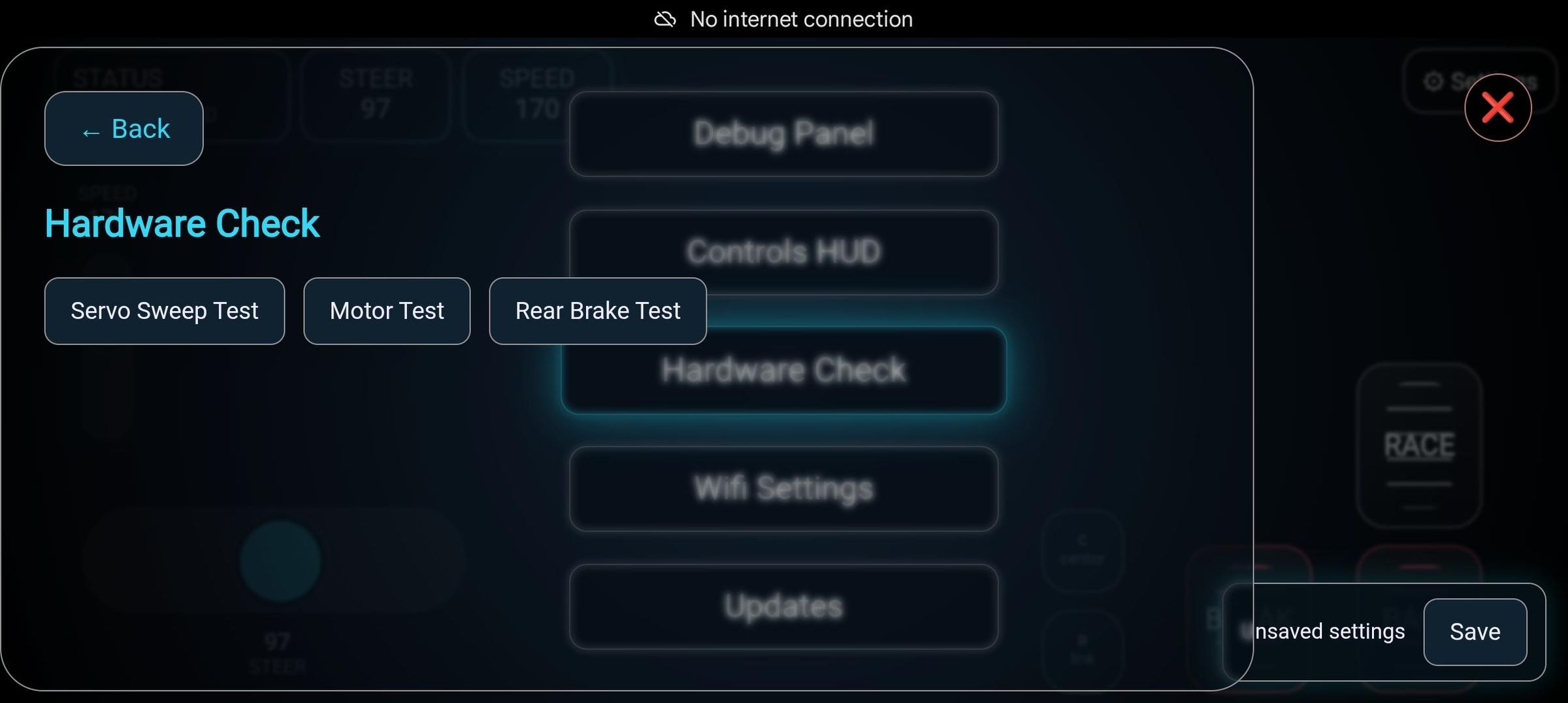
At the Upper Right Corner There a Setting, Go to Settings -> Hardware Test -> All Tests
Run each hardware test and see if the servo and Rear Motor is working as expected.
If Any Tests Fail There's Possible Solutions in the Troubleshoot Section or you can contact me directly.
Troubleshoot
If Everything is Working For You you Can Ignore This Step. You will require any basic multimeter for the troubleshooting purpose.
- Power Supply Debug :
- First thing you should Check if the Battery is Properly charged up to 3.7 volt atleast.
- If the battery seems okay then check if the voltage booster is giving 5 volt at the output or not.
- Check every output power point it should either read battery voltage or the 5 volt.
- Motor Driver Debug :
- First things to check if the motor driver is not working is the Power to both the Main motor driver and the current amplifier.
- If the Power is okay then check if the correct corresponding control pin is going to the current amplifier.
- If the current amplifier connection seems okay then check the four control wires going from current amplifier to main motor driver.
- Servo Motor Debug :
- Check if 3.7 or the battery voltage is coming between the Gnd and VCC header pin for the servo motor.
- If the power is coming then check if the pwm pin is connected to the right place.
- Even after the correct supply and pin connection something is not working then it may be a problem from esp32.
- Main PCB Debug :
- To check the Main pcm remove all the connectors and esp32 only keeping the 5v input from booster and battery input.
- Keep Power on and check each point for correct voltages at the output.
- If the correct power output is coming then place esp32 onto the main pcm and run the code without any hardware connected.
- Now connect to the car's hotspot and open the web controller and go into the Hardware check section. Run servo test and check if the voltage is varying or not on the pin 26 of the esp32, then check at the pwm pin servo headers.
- Same for Motor drivers run the motor driver test and check if the four pins are changing their output accordingly.
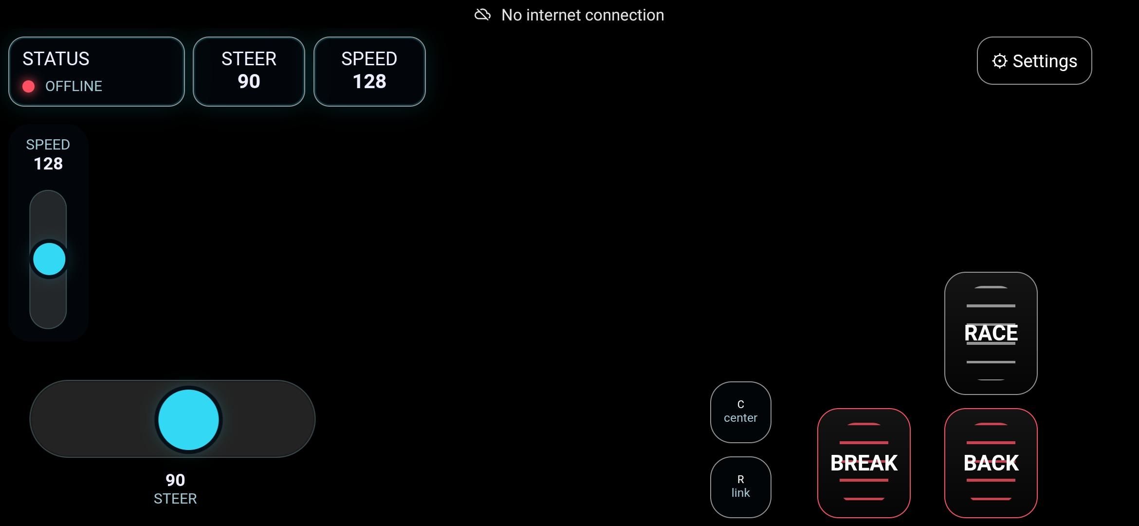
Control Guide
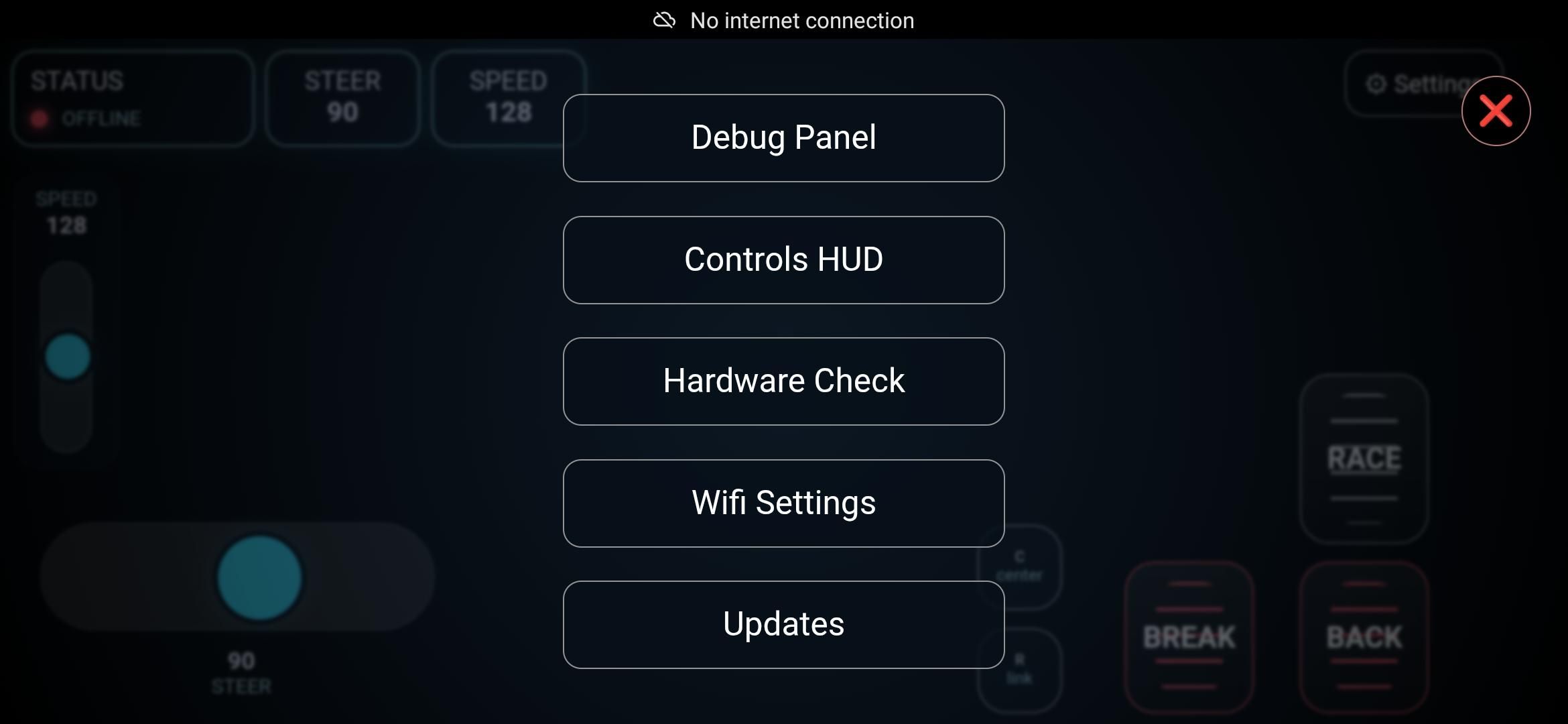
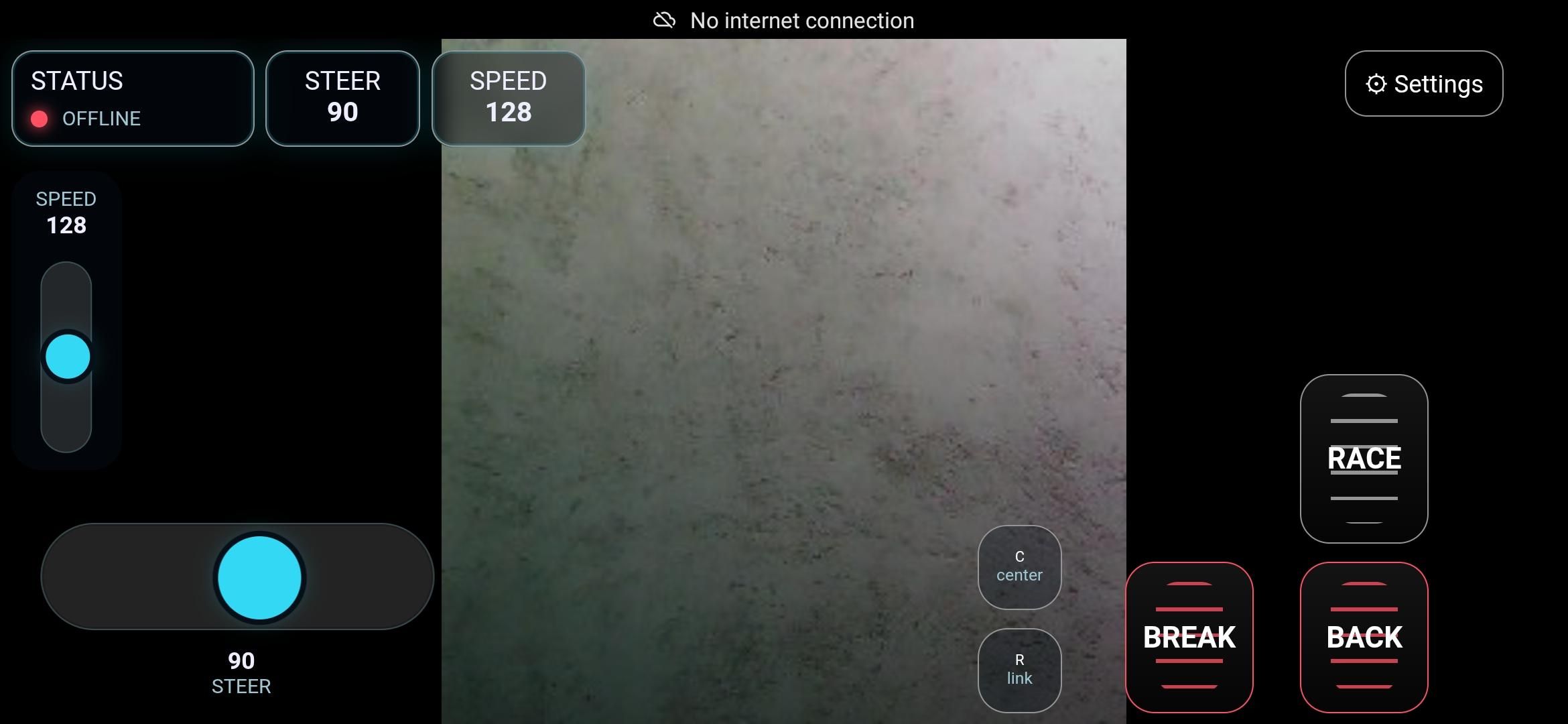
Status Bar :
Status -> Shows Connection Status with Car (Adding manual Connect button)
Speed -> Shows Current Set Speed (Live speed would be cooler)
Steer -> Shows Current Steering angle
Battery -> shows live Voltage and charge of the Battery
Setting Menu :
Debug Log -> Let you see the current command the car is sending or receiving.
Controls Hud -> You can choose the Motor driver options, Default control settings. Advanced settings like servo frequency and Motor Jump start values can be set.
Hardware Check -> Test Hardware Functionalities ( Servo Test, Rear motor test )
Wifi Settings -> You can change Name and Password of the Car’s Wifi
Updates -> You can remotely update the car to the latest software support. Soon may add a customizable update feature.
Left Side Controls :
Speed Bar -> Let you select speed
Steer Bar -> Let you Choose Steering angle (On Finger Up -> Centers the steering)
Right Side Controls :
Race -> Accelerate the Car
Backward -> Reverse Accelerate the Car
Brake -> Apply Brakes ( Dynamic Motor Breaks )
Center -> Centers the Car’s steering
R-link -> Disconnect the websocket and auto reconnect.
Background Live Video Feed :
If ESP CAM is connected then it will show up automatically. I may add its setting in the future updates.
Thank You !
Hope you have made the complete Car & enjoy it as much as I enjoyed it when I first made it.
If you have any suggestions, Doubts or want to talk to me about Electronics or any other topics you can DM me.
Email :- jaypatel3000k@gmail.com
Insta :- @be1jd