Model Rocket Motor Dynamometer (Arduino Uno)
by nightmare.on.scam.street in Circuits > Arduino
3279 Views, 22 Favorites, 0 Comments
Model Rocket Motor Dynamometer (Arduino Uno)
.png)
Hi. My normal YouTube "job" has been chasing and shutting down scammers. I've taken a break from that and have recently been playing around with model rockets, drones and airplanes.
Making model rocket motors is fun but when it gets serious it becomes necessary to measure the motor's performance so that the effect of fine adjustments can be visualised.
This project uses parts available from Amazon (and many other retailers) and there's nothing complicated apart from the code, which of course is downloadable from this instructable later.
There are several modules in the project:
1.Strain Gauge Load Cell
2.Motor Mounting Platform
3.Audio and Visual Warnings
4.Motor Ignition Relay
5.Control System
6.Data Retrieval and Storage
The whole system is designed to be stand-alone - requiring no PCs/Laptops to acquire the motor data. Once stored on SD card, the data can be safely removed from the system and read by a PC etc to generate graphs / charts.
Supplies
Supplies
Note: All the items listed below are from Amazon. The number in parentheses (Amazon B081JNXBSZ) for example, is Amazon's universal item number for that part. There are many other places to buy the components, mostly competitively priced. This list is what I used to make the project myself.
1 x Load Cell With Amplifier - DollaTek 10kg Small Scale Load Cell Weighing Pressure Sensor With A/D HX711AD Adapter (Amazon B081JNXBSZ)
1 x Arduino LCD Shield - KEYESTUDIO LCD Shield Module Display 16x2 Display Module Blue Keypad Shield for Arduino R3 Mega2560 (Amazon B07H3Q3X6C)
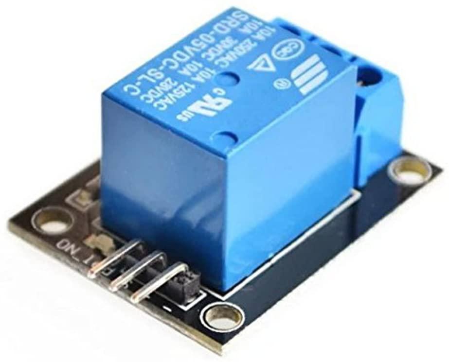
1 x Arduino Relay Module - ICQUANZX 5PCS KY-019 5V One Channel Relay Module Board Shield For PIC AVR DSP ARM for arduino Relay (Amazon B07BVXT1ZK)
1 x Arduino Uno (compatible) - ELEGOO UNO R3 Board ATmega328P ATMEGA16U2 with USB Cable Compatible with Arduino IDE Projects RoHS Compliant (Amazon B01EWOE0UU)
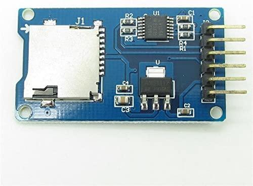
1 x SD Card Module - Pxyelec 1pcs Micro SD Card Micro SDHC Mini TF Card Adapter Reader Module For Arduino (Amazon B07F9LT72N)
1 x PP3 Battery Clip - 5Pack 9V Battery Snap Connector 9 Volt Battery Clips Connector Buckle Plastic Housing, T-type (Amazon B07HD3PBDT)
1 x Pushbutton - SPST Red Momentary Push Button Switch 1 Circuit 1A 250V off-on (Amazon B082VFKJMF)
Various Connection Wires, Heat Shrink, Solder etc.
Case of some sort
Strain Gauge


The strain gauge recommended consists of a bar with some holes drilled in its side. On top and below the holes are some components glued on with epoxy. These components are strain gauge elements. When the bar is pressed at one end, the metal above the hole is stretched. The metal below the hole is squeezed. The elements measure this minute movement by means of a flexible, resistive PCB. As the PCB is stretched the resistance increases. Squeezing the PCB reduces the resistance. Between the Strain Gauge and the Arduino is a processing amplifier which takes the minute resistance changes and converts them into meaningful, readable values.
The Strain Gauge amplifier has 6 connections at one end and only 4 at the other. We are going to use the 4 pin connector - Gnd, Vcc, Data and Clock to join the amplifier to the Arduino. The connection of these pins is shown in the overall wiring diagram. There are 4 wires coming from the Strain Gauge itself, Red, Black, White and Green. They are connected as follows : Red to E+, Black to E-, White to A- and Green to A+
There is a small modification to do to the strain gauge amplifier board. Originally the sampling rate is 8 per second, which is not good enough for our purposes. If you look at the picture of the board you will see a large component calle U7. At the top right of U7 is a power supply pin (pin 16). The pin below it is the sample rate pin (pin 15). What is needed is to carefully apply heat from a soldering iron to pin 15 and lift it up from the PCB a tiny amount. The carefully bend the pin towards pin 16 so they overlap a little. The just quickly solder pin 15 to the top of pin 16.
Don't worry, this sounds much harder than it is. Careful use of a soldering iron and some tweezers will get the job done in no time.
The purpose of the modification is to change to sampling rate from 8 per second to 80 per second. Our system records 800 readings over the course of about 10 seconds, giving a good resolution. If the modification is not done, the results will be disappointingly blocky graphs.
The Arduino LCD Screen Shield

This add-on to the standard Arduino Uno give a few lines of text via a simple LCD screen. The text, in our case, it to give status and warning updates. The add-on is known as a Shield as it plugs into the Arduino Uno and automatically takes the input/output pins it needs. It makes the remainder of the I/O pins available via terminal holes on the board. The Shield also has a number of pushbuttons, which are easily read by the Arduino with some simple code.
There is a down-side to using a shield such as this. Many of the I/O pins become unavailable. If the Shield itself needs them, then they're no available for the user. In the software I had to re-purpose some pins to make more available as Digital rather than Analogue pins as the LCD Shield used up so many.
Frankly, the LCD Shield is not important to the project. It's just useful to see that the SD card is checking out OK or why the system might not be progressing past a particular point. The next version of this Rocket Motor Dynamometer will not use the LCD shield, but will use audio cues to show status.
Relay Module

The idea of the relay module is to improve safety by isolating the Arduino and it's associated circuitry from the rocket motor igniter. This project is designed to automatically ignite the rocket motor by powering an electric igniter / match.
The module is controlled by the Arduino, which energises the relay when the system determines that the motor should be ignited. When the relay is energised, a contact closes, switching power to the igniter. In my case I use simple electric match igniters. They can reliably be triggered by a PP3 battery, switched by the relay.
There are only 3 terminals on the relay module - Gnd, Vcc and Signal. The signal wire is held low by the Arduino until ignition time, only then does the Arduino make the signal wire high. At the end of the firing / measuring cycle, the relay is once again de-energised.
A word of caution - I purchased 5 relay modules from Amazon. It seems I got a bad batch because 3 out of 5 were faulty. Oddly the VCC pin was not connected to the pad beneath it, even though it was soldered on the back. I contacted the manufacturer to let them know they had a faulty batch. Check the module before using it.
The Micro SD Module


This module serves to record the data from the Strain Gauge. The interface to the Arduino is called SPI and it is a bit of a problem as we have a distinct lack of pins spare after installing the LCD Shield. However, I found a way around it in software so don't worry.
The module takes data from the Arduino and writes it into a file that was created onto the Micro SD card. I designed the software to check the card quite early in the sequence to see if various criteria were met.
Firstly the card had to be installed and properly formatted.
The software then reads the directory and looks for files with the first characters "rdyno". The file system is such that there will then be a 2 digit number. The software looks for the highest number already used, then adds one. For example, if the last run produced a file with the name rdyno57, the software will generate a new file called rdyno58. As of now there is no real-time clock to date-stamp the files but you'll know that the highest file number is the most recent.
In the next version I will remove the LCD Shield and add a real-time clock to properly record date/time and exact run time for each motor test.
Arduino Uno


This is the brain of the system. The program (sketch) is stored here and it controls all the peripherals, moves data from one place to another and manages the control sequence so that everything works as we want it to. I've produced a simplified flow-chart which shows the various steps.
Immediately on power-up the average no-load reading from the strain-gauge is being calculated continuously. This is because there is some temperature and probably moisture sensitivity in the strain modules so a fresh zero is needed every time. Also, the weight of the motor needs to be zeroed out (Tare).
On pressing a button (either the Select button on the LCD Shield or the remote button) lots starts to happen at once. Immediately the button is pressed there is a beep to confirm the button was pressed. This may sound petty but how would you know not to hang around unless something told you ?
The program then checks that the SD card is both installed and formatted. It is easy to forget to install the card before starting the test and the last thing you want is for the motor to fire up perfectly and have no data recorded. If there is no properly formatted SD card installed there is a message displayed on the LCD and the system goes back to standby.
If the SD card is properly recognised the software searches for previous data files. So it doesn't over-write something important, the system checks for the highest file number then adds one to it, making a new file one number higher than the last one on the SD card. The software then opens the file on the SD card ready to receive data.
There is an audio and visual countdown from 10 and at the end an extended tone telling you that stuff's about to happen.
The SD card data file starts accepting data from the Strain Gauge. Immediately thereafter the relay module is energised, which should ignite the motor. The SD card records 800 readings from the Strain Gauge before closing down the system.
The SD card file is closed and the relay module is de-energised.
The system returns to standby.
It just took me about 10 times longer to write this explanation than it takes for the events to happen in real life. The bit that feels longest is the countdown but you can tweak that if you are feeling brave and have a good escape route.
Construction Hints and Tips


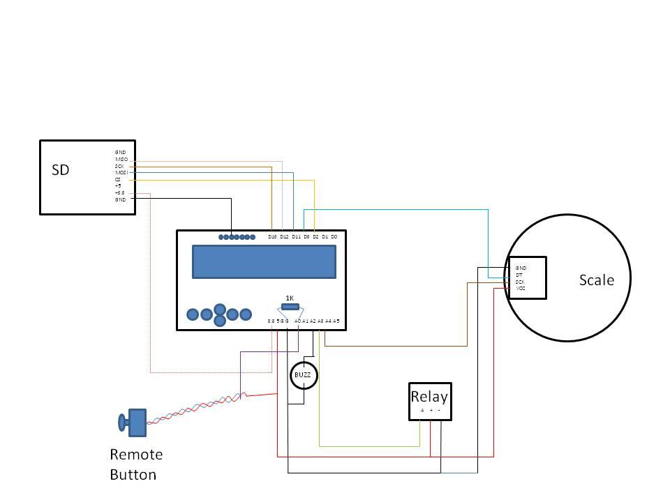
The schematic above shows how to interconnect each module. There are a few things to note.
- THIS WAS MEANT TO BE A PROTOTYPE. IT's MESSY AND COVERED IN ROCKET MOTOR DEBRIS. IT KEEPS WORKING SO I'M NOT GOING TO "FIX" IT YET. Please don't grumble about the messy wiring or the dirty plywood.
- The Strain Gauge Amplifier is not connected to the Sensors on delivery so the 4 wires coming from the load cell will need to be soldered to the amplifier board.
- Keep the wires as short as possible from the Strain Gauge Amplifier to the Arduino
- The Strain Gauge Amplifier requires a small modification to increase the sample rate to 80 samples per second.
- In the whole construction, the Strain Gauge Amplifier proved to be the most troublesome. Initially I soldered pins into the connections at each end of the board. This proved to be a wrong decision. For some reason I had to remove the pins from the Arduino end of the board and with the pins came lengths of PCB track. I'm not saying the PCB was badly made and I'm definitely not saying that my soldering/desoldering technique (honed over 50 years) is bad. Let's just say the tracks and pads of the PCB are very fragile. To fix this I had to solder wires to other parts of the PCB that the now-missing tracks went to. That's not as hard as it sounds but just this word of caution - solder the wires from the Strain Gauge and the Arduino directly into the holes of the connection pads. Don't bother with pins.
- The LCD Shield should be plugged into the Arduino Uno before commencing soldering. Almost all of the Uno pins needed are echoed on the LCD Shield. There are one or two pins that have to be connected to the Shield pins rather than the echoed terminals.
- Consider the layout of the components. The SD card module should be well shielded against debris from the rocket motor, for example.
- The Buzzer is connected to the Arduino with short wires and blobbed onto the board with hot-melt-glue.
- I decided not to connect the external switch but I did put the pull-down resistor to it's pin to prevent accidental initiation.
- Some of my prototype wiring went across the LCD so I used the well known method of putting a bloc of "Blu-Tack" to hold the wires out of the way.
- The pictures in this section are from the prototype, which was thrown together rather quickly. I admit it's not the tidiest job I have ever done but it works, and has kept working. So on the principle of "if it isn't broken; don't try to fix it", I've been very lazy and I haven't rebuilt it - yet.
- The rocket motor itself needs to be mounted on top of the Strain Gauge. To lift the motor above the Arduino I put an empty tape reel (75mm dia x 50mm high) onto the acrylic plate and secured it with hot melt glue. I then glued a piece of thin plywood (A5 size) onto the tape reel. Directly above the centre of the acrylic disk I glued the rocket mount - two pieces of half pipe. I hope I don't need to stress that the motor fits into the mount pointing UPWARDS. The top piece of plywood looks disgusting. The fact is that rocket motors produce lots of debris, most of which will fall down onto the plywood. Once again, a rather bodgy attempt while producing a prototype that has just kept working.
- The output of the relay module requires a separate power supply to energise the electric igniter. I used a 9 volt PP3 battery and a battery clip. The positive from the battery goes to the common of the relay module. The N/O connection of the relay module has a 10 cm piece of wire connected to it. I use the ends of the electric match and just twist the wires together, one to the battery negative and one to the wire coming from the relay N/O terminal. I'm sure there are better ways to do this, but I dislike crocodile clips and screw terminals are too fussy. Let me know your solution.
The construction is simple. Follow the connection diagram and keep the wiring tidy. There is one connections that needs to go to the LCD Shield Ground pin, rather than the echoed Uno pins. I think I've listed all the problems here so if there's anything you're not sure of, drop me a line and I'll try to help.
Software

I had originally intended to give the sketch file and leave it there but I think some explanation is worthwhile. What I've done is added numerous comments in the sketch so it's quite easy to understand. The final version has no external outputs. What I mean is that there is no connection to a PC that might help with troubleshooting. Originally I had dozens of Serial.print commands embedded at strategic points to see what was going on. I removed these in the final version.
The flowchart shows how the software is intended to work. The default "Standby" state is where most of the modules of the software return, say after operation or if a problem is detected.
To prevent mishaps, the software checks the SD card and reads the directory. If it finds any existing data files, it looks for the one with the highest number and then creates a new file with 1 added. For example, if it finds rdyno73 as the highest number file it will create a new data file called rdyno74.
Here are some notes about calibration:
There is a constant called calibration_factor, which in my case was -214.7. This value helps the software correctly work out the weight on the Strain Gauge.
While in standby mode, the software constantly calculates the current TARE value.
I calibrated my system by using a plastic container with 2 liters of water in it. I weighed it on normal kitchen scales until I had a total weight of 2 kg. I then used that weight on the motor mount area and worked out the difference between the recorded weight and the actual weight. After a few iterations I was able to get a reading of exactly 2kg every time.
To make calibration a little easier you can add a line of code to the Sketch within the section that writes to the SD card below. This will allow you to monitor the scale data on a PC/Laptop in real time.
There is a section of code that looks at the buttons on the LCD Shield. The buttons create a numerical value, depending on which button is pressed. For the Select button, the range of values was between 500 and 750. If the number read by the analogue pin is between these numbers, the software recognises that the Select button has been pressed.
The section of code that reads the scale and writes the data to the SD card is remarkably small:
for (int i = 0; i <= 800; i++) {
dataFile.println(scale.get_units(), 1);
}
To monitor in real-time modify the above code to this :
for (int i = 0; i <= 800; i++) {
dataFile.println(scale.get_units(), 1);
Serial.println(scale.get_units(), 1);
}
The code reads the scale 800 times, writing each value to the SD. As soon as the 800 values are recorded the file is closed to protect it. The modified code also sends the measured scale data to the serial monitor. It slows down the data collection quite a lot. With the Serial.println code added the 800 recordings take about 8 seconds longer.
You can name the data file anything you want providing the text part is 6 characters or less. The filename system is limited to the old 8.3 system so the maximum number of characters before the period is 6 alpha followed by 2 numbers. If your SD card has been used for almost 100 tests, you would need to either store the data files somewhere else and wipe the SD card or if you're lazy you could just set the filename to something new and do another 100 test. Seriously though, if you archive your SD card and remove the files from it, change the base file name because you don't want to end up with another bunch of files called rdyno01 etc.
Using the Dyno and Interpreting the Data


The dynamometer should be positioned in a safe place well away from buildings and people on a firm surface. The rocket motor needs to be positioned in the clamp facing UPWARDS. Before connecting the igniter, make sure the 9V battery is disconnected. Twist / connect the wires from the igniter to the relay/battery connector and place the igniter in position in the motor. Visually check that the igniter relay is NOT energised. Clip the connector to the 9v battery.
Make sure the SD card is installed then have a look around. Do you have a clear route to safety ? Is there anyone around that could get too close ? Remember, once the button is pressed there is no safe way to stop the system from firing.
Press the "Select" button on the LCD Shield or press the remote button. You should hear a confirmation beep. At this point MOVE AWAY TO A SAFE SPACE. Rocket motors do fail and if there is a CATO you want to be as far away as possible.If all is well with the SD card you will hear a series of 10 beeps at one second intervals followed by a long beep. At the end of the long beep the igniter relay is energised and the scale measurements are begun.
The igniter should fire and ignite the motor. Normally the igniter is ejected from the motor by the thrust. When the motor stops burning wait for things to cool down. Check the igniter relay is not energised then remove the SD card from the SD module.
I personally use MS Excel but any spreadsheet software will work just as well. Load the rdynoxx.csv file into the spreadsheet and select all the data apart from the first and last numbers. The first number is a time-code saying at which millisecond the recording started and the last number is another time-code saying at what millisecond the recording stopped. You can use these for further analysis. All the 800 numbers in-between are data from the load cell. Once they're selected you can, for example, simply select insert graph and display the rocket data as shown above. There are plenty of other ways to analyse the data but they're outside the scope of this instructable.
If you have any questions, just get in touch and I'll do my best to answer.