Modern Zeer Pot: a 3D-Printed Passive Evaporative Cooler
by smmazulhaque in Workshop > 3D Printing
91 Views, 1 Favorites, 0 Comments
Modern Zeer Pot: a 3D-Printed Passive Evaporative Cooler
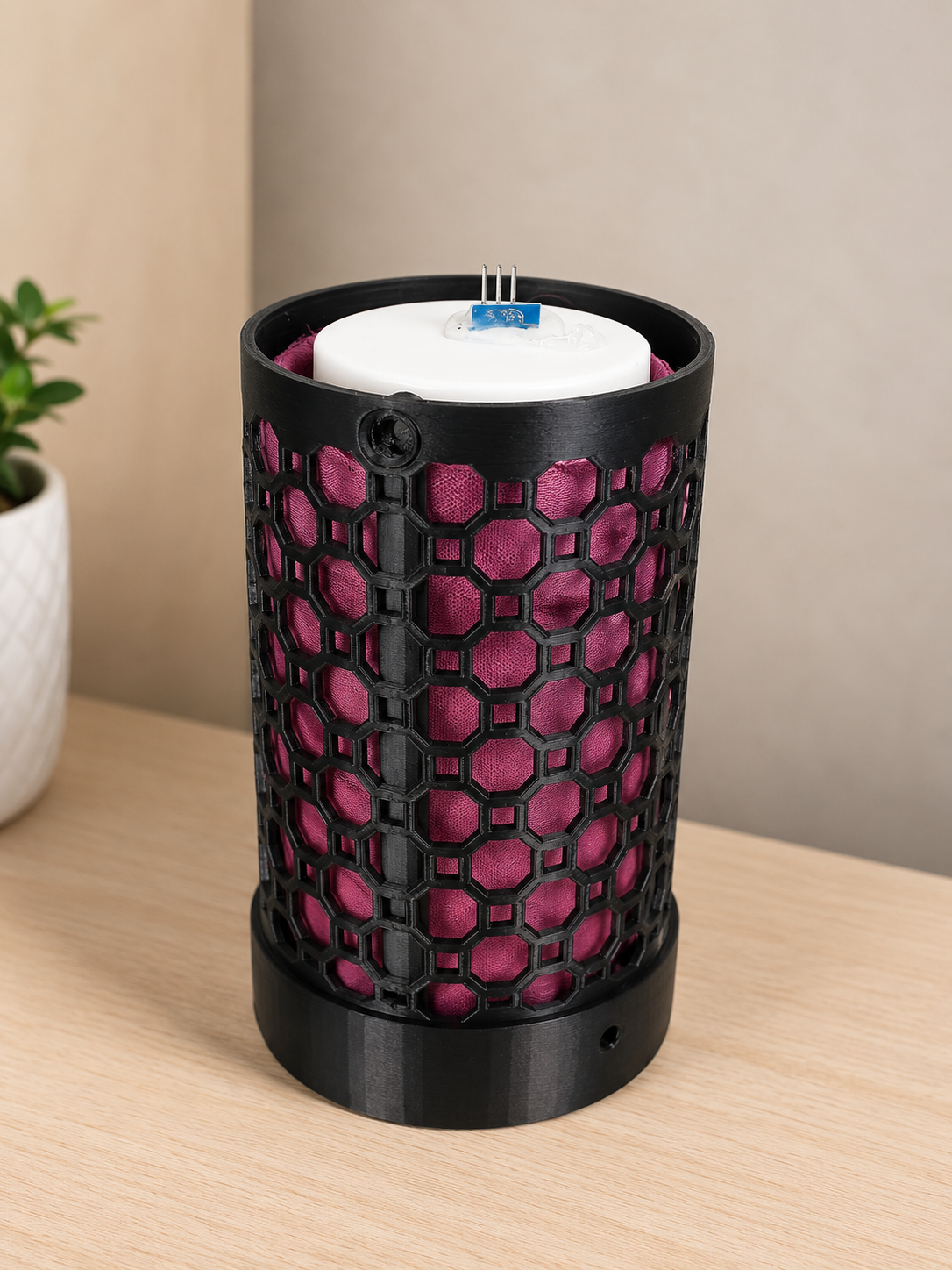
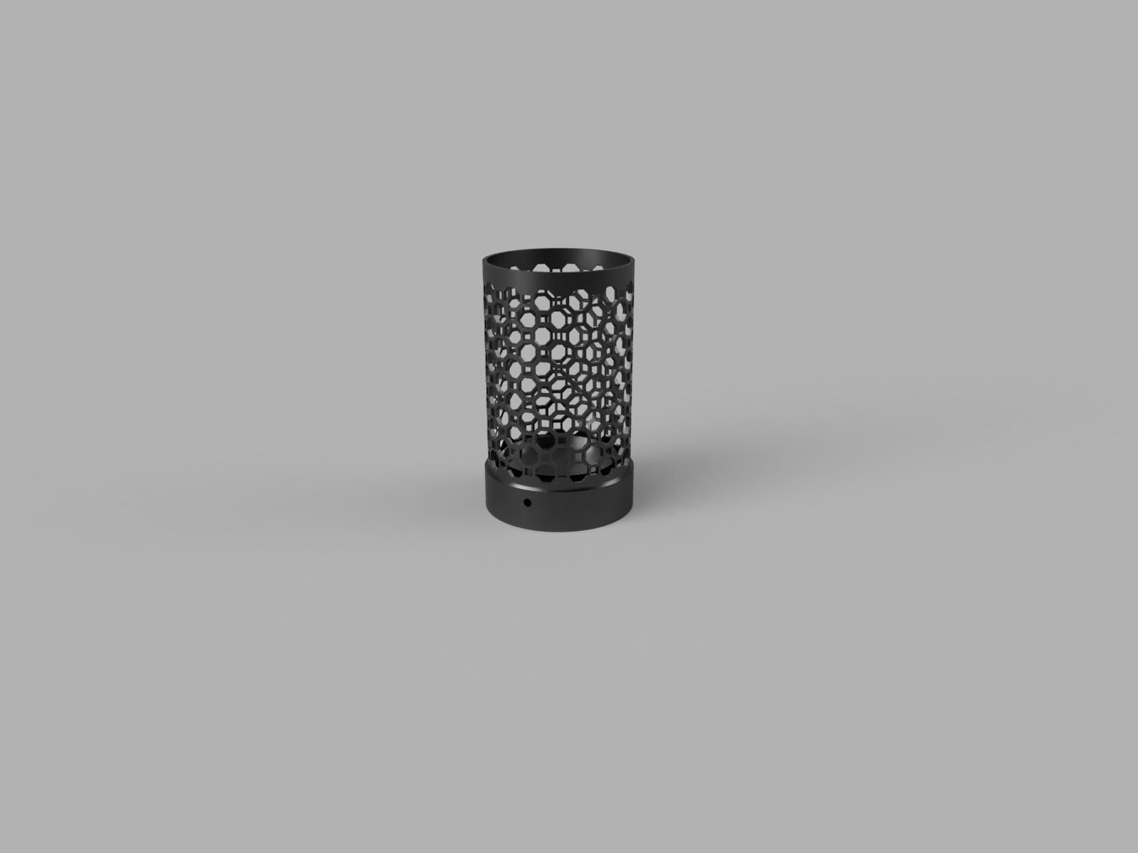
What if you could build a small cooler that works without electricity, batteries, compressors, or moving parts?
This project is a modern take on the traditional Zeer pot, or pot-in-pot cooler. In a traditional Zeer pot, a smaller pot is placed inside a larger pot and the gap between them is filled with wet sand. As the water in the sand evaporates, it removes heat from the inner pot and cools the contents.
I wanted to explore whether this principle could be redesigned using 3D printing and a lattice structure.
The main inspiration came from the paper “Enhanced evaporative cooling using additively manufactured PLA–wood composite lattices”, DOI: 10.1016/j.ijheatmasstransfer.2026.128655. The study investigated several 3D-printed lattice geometries as evaporative cooling pads. Among the tested designs, the octagonal lattice produced the highest temperature drop of 19.7°C and a wet-bulb effectiveness of 0.93, which the authors associated with its large air–water contact surface.
My approach is different from that study. Instead of using the 3D-printed lattice itself as the wetted evaporative material, this project works more like a traditional Zeer pot. I replaced the traditional wet sand with cotton fabric that wick water from a reservoir below, keeping the cooling surface continuously wet. The outer octagonal PLA lattice provides ventilation around the wet cotton.
The result is a compact, portable evaporative cooler with a removable glass storage chamber, refillable water system, replaceable cotton wicking layer, and an optional temperature sensor for measuring its performance.
In this Instructable, I will show how I designed, 3D-printed, assembled, and tested the cooler.
Supplies
Main Components
- Glass jar — approximately Ø70 × 90 mm
- Cotton fabr/wicking material — used to transfer water from the lower reservoir to the cooling surface
- PETG filament — for the outer lattice, base, lid, and water-fill components
- Water
Temperature Monitoring
- Arduino Nano
- DHT11 temperature/humidity sensor — used to measure the temperature inside the glass jar
- 0.96-inch OLED display
- Jumper wires
Tools
- 3D printer/3D printing service
- Scissors/cutting tool for preparing the cotton
- Basic hand tools
From Concept to 3D-Printed Design
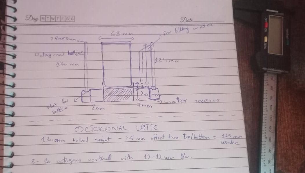
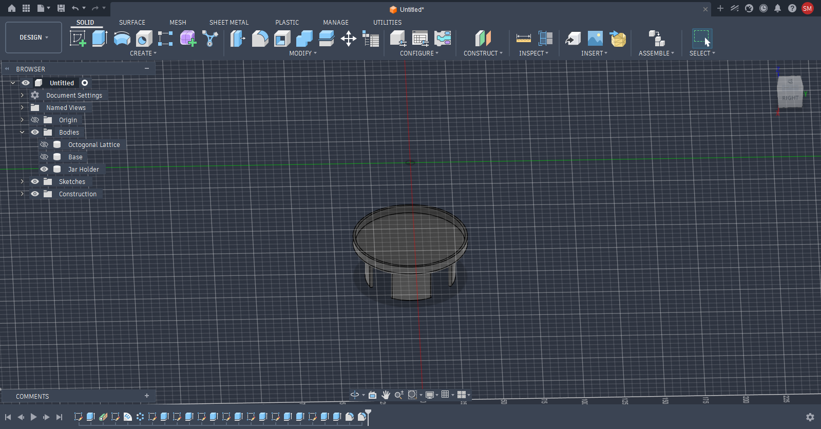
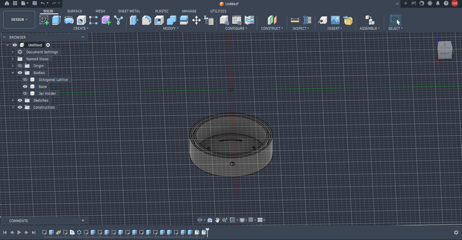
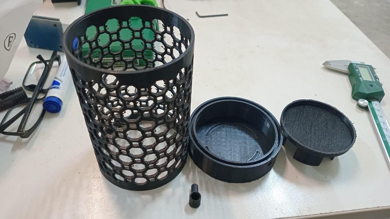
Before starting the CAD, I first needed to find the glass jar, since its dimensions would determine the size of the rest of the cooler. I recycled a glass jar from home with an approximate 67.5 mm diameter and 124 mm height.
I started by sketching the concept on paper to work out the basic arrangement and dimensions.
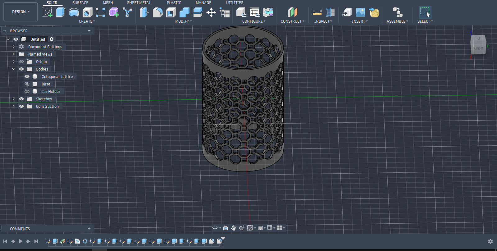
I then moved the design into Autodesk Fusion, using the education version provided through my university. To make the cooler easier to manufacture and assemble, I divided the design into four separate parts:
- Outer wall — contains the octagonal lattice and surrounds the wet wicking layer.
- Jar holder — supports and locates the glass jar.
- Base — acts as the water reservoir and supports both the outer wall and jar holder.
- Funnel — connects to a straw/tube and provides an easy way to refill the reservoir.
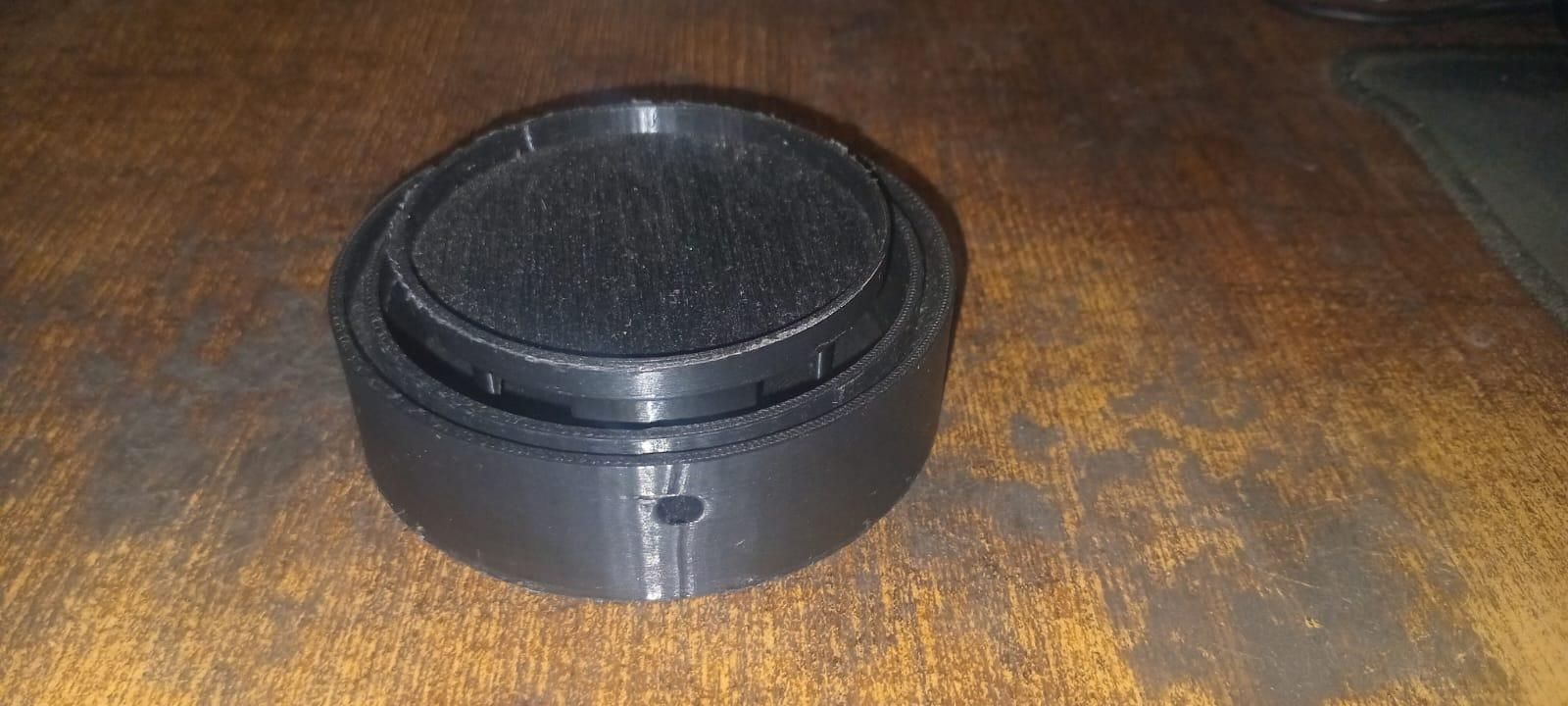
The base also includes a small overflow hole to prevent the reservoir from being overfilled.
Why the Outer Lattice?
At first, the outer lattice might seem unnecessary. With wet cotton wrapped around the jar, air flowing directly over the surface should already provide evaporative cooling.
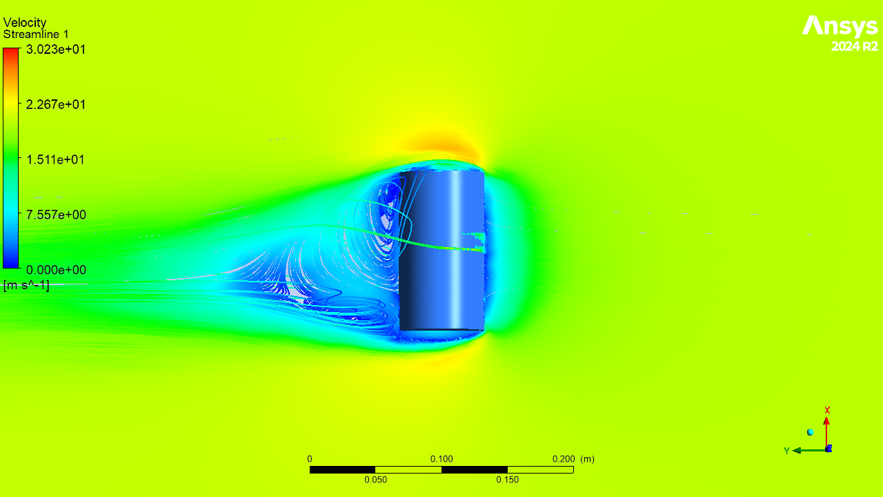
However, I designed this cooler for a specific use case: placing it in front of a window where airflow predominantly comes from one direction. With a plain cylindrical jar, the airflow can separate around the jar and create a relatively stagnant region behind it.
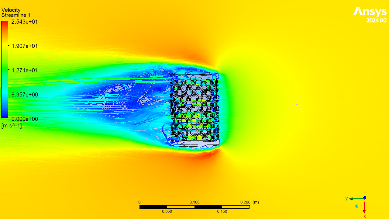
Since greater air–wet-surface interaction should promote evaporation, I explored whether an outer lattice could help distribute the incoming air around more of the wet surface.
I designed the outer wall first, starting with an octagonal lattice. I selected an approximately 11.5 mm octagon size, which allowed the cells to be distributed evenly around the cylindrical wall. The remaining components were then modelled around the outer wall and the dimensions of the glass jar.
I later compared the plain jar and lattice-covered design using ANSYS Fluent to study the airflow streamlines and velocity distribution.
The simulation showed that the lattice changes the airflow around the jar, but also revealed a limitation: a significant portion of the incoming air passes around the lattice rather than reaching the wet surface directly. Since I had already printed the parts by this stage, I decided to continue with the octagonal lattice for the physical prototype and test its actual performance experimentally.
I will continue investigating alternative lattice geometries through CFD to find a design that provides better airflow distribution over the wet surface. This optimization can be covered in Part 2 of this Instructable.
CAD and 3D Printing
All four components were modelled in a single Fusion file as separate solid bodies. The fitting tolerances were adjusted according to the Anycubic Kobra 3 printer used for fabrication.
The parts were 3D printed in PLA and took approximately 4 hours to print as a complete set. The printed parts required some post-processing, mainly cleaning and deburring, before assembly.
The STL files are provided below so the design can be replicated. However, the design is based around the dimensions of the glass jar used in this project, so a jar with the same or very similar dimensions should be used for direct reproduction.
Building the Wicking and Water System and Assembly of the Pot
.jpeg)
The first step was to join the jar holder and base using adhesive to form the main support and water reservoir.
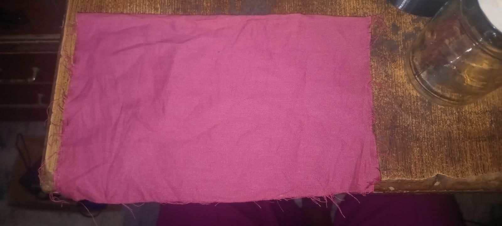
For the wicking layer, I cut the cotton fabric to approximately 138 mm in height, with the width made about 10 mm greater than the jar's circumference. This allowed the fabric to wrap completely around the jar while extending down into the water reservoir.
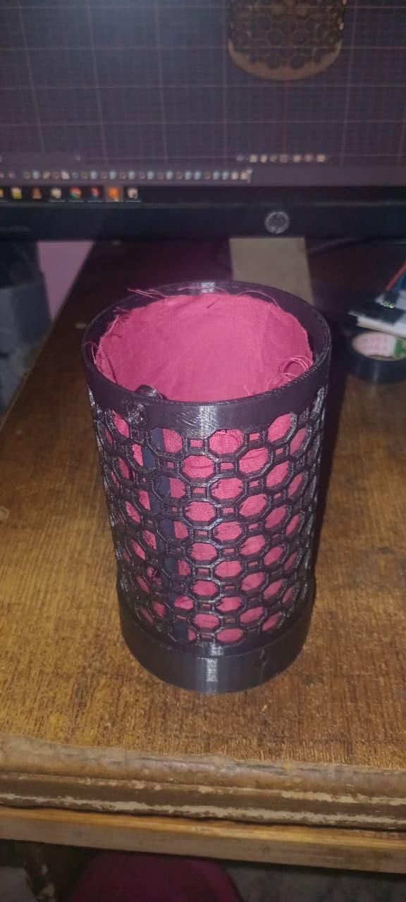
I then placed the jar holder and wicking fabric around the glass jar, ensuring that the lower part of the fabric could reach the water reservoir and continuously wick water upward.
Finally, I assembled the funnel and straw, outer octagonal lattice, jar holder, and base together to complete the cooling assembly.
Temperature Monitoring
I initially planned to use a bimetal thermometer mounted inside the glass jar, but instead decided to make use of electronics I already had available: an Arduino Nano, DHT11 sensor, and 0.96" OLED display.
I kept the electronics simple and used a breadboard with jumper wires. There are already plenty of tutorials covering the basic Arduino–DHT11–OLED connections, so I will not repeat the complete wiring procedure here.
I also modified the cooler lid so that the DHT11 sits inside the glass jar, while only its connection pins extend outside. This allows the lid to close while keeping the sensor inside the storage chamber.
The Arduino code is attached here. One important detail is that my OLED uses the SH1106 driver, so the included code is written for SH1106. If you build the same system, check the driver of your OLED and make the necessary changes to the code before uploading it.
Testing and Results
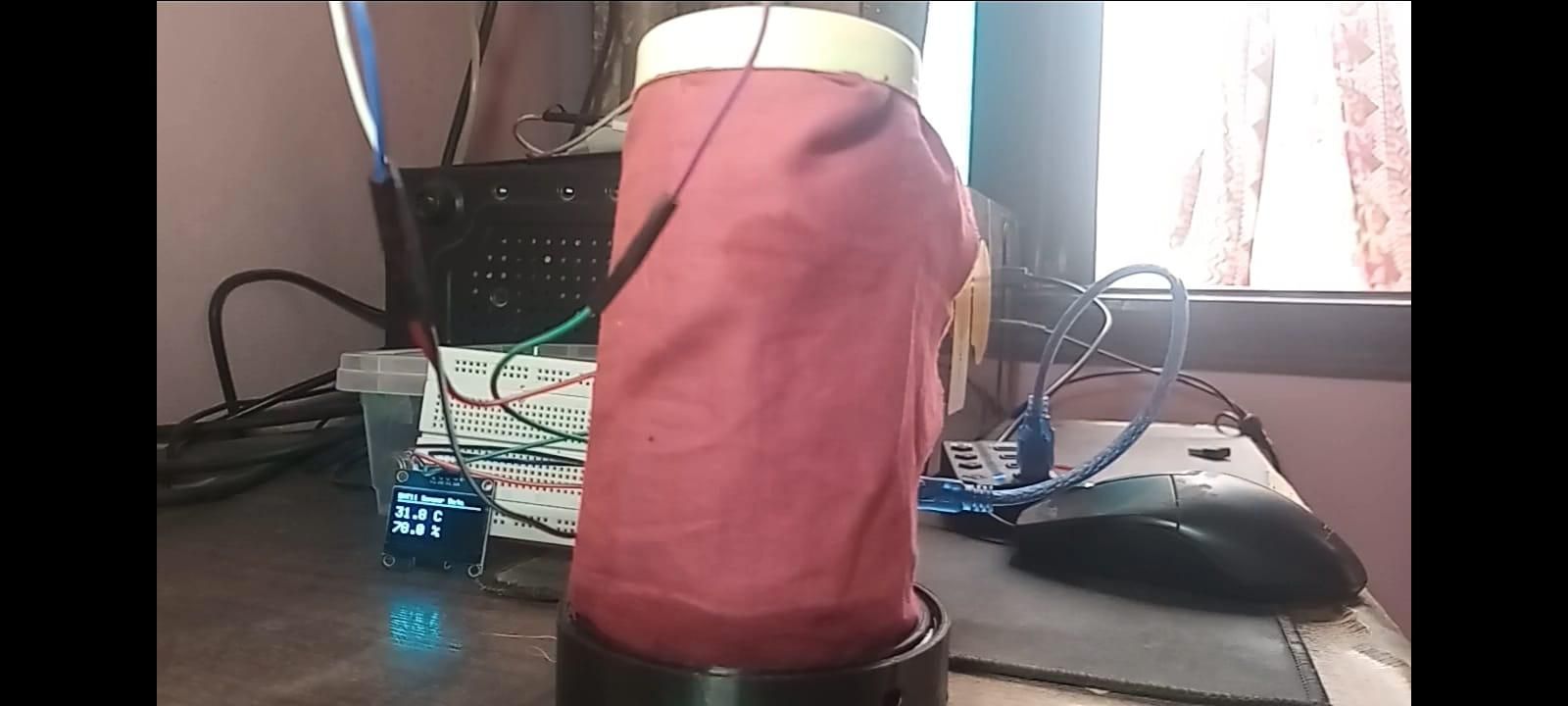
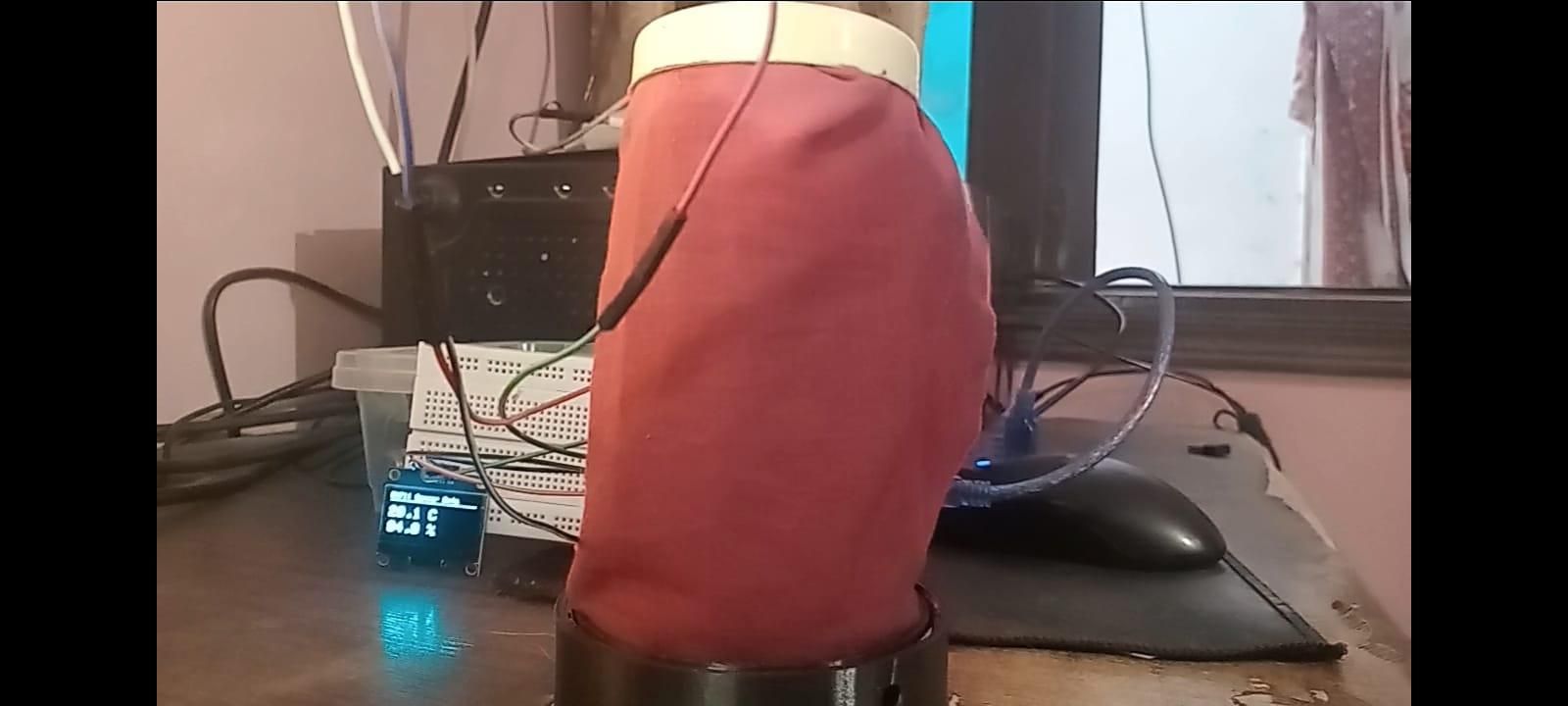
I first tested the cooler without the outer lattice to establish a baseline. The ambient temperature was approximately 32°C, with relative humidity around 70%.
I started recording as soon as the cotton wicking began. After approximately 1 hour, the cotton had almost completely wicked water to the top, while the temperature inside the jar had dropped to approximately 28°C. At the same time, the measured humidity inside the jar increased to around 85%.
I then repeated the test with the octagonal lattice installed and obtained broadly similar results, with the temperature reaching approximately 28°C under similar conditions.
This initial ~4°C temperature reduction is consistent with the expected behavior of an evaporative cooler. In traditional Zeer pots, cooling typically begins after the sand is fully saturated and the wet cover is applied, with the temperature stabilizing over the following few hours. In my test, however, I started recording while the cotton was still wicking, so the cooler had not yet reached its fully wetted condition.
For a more complete test, I would ideally continue recording for at least another 1–2 hours after the cotton becomes fully wet. However, the current testing conditions are far from ideal. Karachi is a coastal city and the test was conducted during the monsoon season, when humidity is relatively high. High ambient humidity reduces the evaporation potential of the cooler.
The cooler is primarily intended for use during April–June, when Karachi experiences much hotter and generally more suitable conditions for evaporative cooling.
Overall, the initial results are consistent with the expected operating principle, but they are not sufficient to establish the performance advantage of the octagonal lattice. Proper comparison would require longer tests under controlled and preferably hotter, lower-humidity conditions.
I plan to continue this work in Part 2, where I will investigate improved lattice geometries using CFD and physical testing. I am also open to collaborating with others who can test the design under different environmental conditions.
Lessons Learned and Future Improvements
Lessons Learned and Future Improvements
This first prototype helped identify several areas that can be improved in the next version.
- Lattice optimization: The current octagonal lattice is only the first iteration. I plan to test different lattice geometries and orientations through CFD to find a design that distributes airflow more effectively over the wet cotton surface.
- Funnel design change: The current design makes it a little difficult to add water the reservoir due to its small size, plan is to either completely redesign the how water is added to the reservoir or make the funnel more big.
- Thermal CFD: The current simulations were limited to airflow/CFD analysis; no thermal or evaporation modelling was performed. Once I develop a better understanding of thermal CFD, I plan to add thermal analysis to evaluate the cooling performance of different lattice designs before physically printing them.
- Easier cotton installation: Installing the cotton fabric around the jar was somewhat awkward and fiddly in the current design. The next version will include a simpler method for installing, removing, and replacing the wicking material.
- Water-reservoir sealing: After approximately five testing cycles, the base began leaking water. The reservoir therefore needs a better sealing strategy in the next version.
- Longer and better-controlled testing: Future tests should run for longer after the cotton becomes fully saturated and should ideally be performed in hotter, lower-humidity conditions, where evaporative cooling is more effective.
- Experimental validation: The next iteration will compare improved lattice designs experimentally rather than relying only on simulation.
- Part 2: I plan to continue the project as a Part 2, documenting the improved lattice designs, CFD analysis, and additional experimental results.
The goal of the next iteration is therefore not simply to make the cooler colder, but to make the entire system more effective, easier to assemble, more reliable, and better validated through simulation and experimentation.
I would also be very happy to collaborate with others working on similar problems. If you would like to test the cooler in a different climate, help evaluate the next lattice design, or provide technical guidance, I would be grateful to hear from you. Such collaboration could help validate the design under conditions that I cannot reproduce locally and make the next iteration more useful.