Modular 3D-Printed Affordable Housing: Designed to Combat Homelessness Through Innovation and Sustainability
by ssk2008345 in Design > 3D Design
191 Views, 9 Favorites, 0 Comments
Modular 3D-Printed Affordable Housing: Designed to Combat Homelessness Through Innovation and Sustainability


Hello, I’m SK, a rising junior at Ballantyne Ridge High School in Charlotte, North Carolina. I have a strong passion for CAD and design, and I currently serve as one of the lead designers for my FTC robotics team, Circuit Breaker 21829. I enjoy competing in CAD competitions because they offer a chance to challenge myself and improve my skills. After hearing about this contest from several friends, I was inspired to participate and showcase my talents by creating something purposeful that can make a real difference in the world. My inspiration for this project came from the recent California wildfires, where I saw how many people were negatively affected and left stranded after losing their homes. This motivated me to design a solution that could provide affordable and sustainable housing for those in need. Thank you for taking the time to read through my project.
Supplies
Materials :
- Gorilla glue
- Locktight super glue
- Clear Acetate Sheets
- CraftSmart paint
Tools;
- Pencil
- Inch tape/ a ruler
- A marker
- Some thing pointy to spread the super glue
- Gloves
- Scissors
- Ruler
- Eraser
- paper
Software:
- Fusion
- Bambu studio
Hardware:
- laptop
- 3D printer
Inspiration:
On January 7th of 2025, California was devastated by a series of massive wildfires. The Hustle Wildfire, originally known as a Sylmar fire, caught my attention for the destruction it caused. I remember sitting with my family in our living room, watching the news broadcasting flames engulfing entire neighborhoods in Los Angeles. Watching entire communities of homes being reduced to ashes and families being forced onto the streets, left homeless because their houses couldn’t withstand the fire was heartbreaking. Los Angeles is known for its destructive wildfires, and Sylmar is a small community in the city that is frequently affected. This is largely due to its location near dry hills filled with dry grass and bushes, which are highly flammable. In addition to being wildfire prone, Sylmar also struggles with high rates of chronic homelessness. These recurring wildfires only make the situation worse, displacing more people and making it even harder for vulnerable communities to find safe, stable housing.
You can see Sylmar’s location in relation to los angeles on the map below:

Source: https://planning.lacity.gov/plans-policies/community-plan-area/sylmar
The Problem
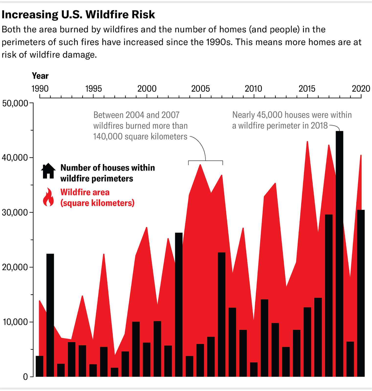
California experiences the most devastating wildfires in the world. Each year, wildfires burn millions of acres, destroy thousands of homes, and displace entire communities. As temperatures keep rising the probability of wildfires also increases, making them much more destructive.
The graph below shows that California wildfires are becoming increasingly destructive, burning more land each year.
In places like Sylmar, a community located near dry hills and brush, the risk is especially high. Wildfires can spread quickly through dry grass and vegetation, often reaching homes before residents can evacuate and get to safety. Many of these houses are built from materials such as wood which are not typically fire-resistant, making them extremely vulnerable to catch on fire.
But the damage goes beyond burnt buildings. Wildfires leave families homeless, especially in these dry areas which already struggle with increasing rates of chronic homelessness and poverty. According to the Los Angeles Area Chamber of Commerce, Los Angeles is home to 34,398 chronically homeless individuals. Many of them lack access to proper education, essential resources, and stable housing, making it difficult to break the cycle of homelessness. Emergency shelters are often overwhelmed, so people are left with nowhere to go. Additionally whitehouse.gov finds, Los Angeles represents 10% of the total population of homeless veterans in the United States. Many of these veterans face unique challenges on top of the challenges of being homeless, for example PTSD, physical disabilities and mental difficulties, which makes it even more difficult for them to reintegrate back into the economy and get proper housing.
Organizations like the LAHSA are constantly trying to tackle the challenges homeless people face and support them in any manner, however the situation is only getting worse. For those already living on the streets, wildfires pose a life-threatening danger, with the smoke, flames, and heat making survival even harder.

Scenes like the one in this image are becoming far too common in California. This ongoing crisis highlights the urgent need for affordable, fire-resistant housing in wildfire-prone communities like Sylmar.
Another major issue in California is the high consumption of fossil fuels, due to which a lot of Co2 is released into the air. Not only does this emission hurt the environment it also severely pollutes the air people breathe, putting their life at risk. According to SolarPower.guide, Carlifronia had the second-highest annual CO2 emissions in the United States in the year 2024. U.S Energy Information Administration (EIA) shows that most of Colifronia’s fossil fuel consumption is mainly on electricity generation and transportation. Rising Co2 emissions due to significant fossil fuel usage, are harmful to both the environment and public health. As emissions continue to grow year by year, more lives will be at risk due to the effects of climate change and air pollution. High Co2 emissions contribute to global warming which is one of the main reasons why California is increasingly prone to wildfires. As global warming temperatures rise, the climate gets hotter in California, causing the forests to dry out increasing the risk for forest fires.
source:https://solarpower.guide/solar-energy-insights/states-ranked-carbon-dioxide-emissions
The Solution
To address the problems discussed in the last step we need to create housing that is affordable for the chronic homeless people, sustainable for the environment, and customizable to preserve creativity and avoid producing indistinguishable units.
90% of all houses in California are built from wood making it extremely flammable. This indicates the major root cause of the problem which is the material the houses are built from. To truly address the problem we need to change the material the houses are built from. After some research I found that houses that are built from concrete never burn down, and this is because its primary components, cement and aggregates like gravel and sand, are chemically inert and have high melting points. This makes it the perfect material for the houses to be built out of to ensure that they never really burn down into ashes. However the problems I ran into was that creating houses from concrete is really expensive due to labour requirements and constructions costs. Still, I kept researching it, and that is when I discovered 3D printing concrete. It uses the same strong, fire resistant material but removes the variable of manual labour out of the equation. The process is completely automated with a single robot in the middle of the structure extruding the concrete in desired shape (you can see this in the image below). This not only lowers the cost significantly, but also speeds up the construction time of the houses, making it a practical solution for this cause. An article written on Dwell.com finds that a small section of houses can be created in only 48 hours!
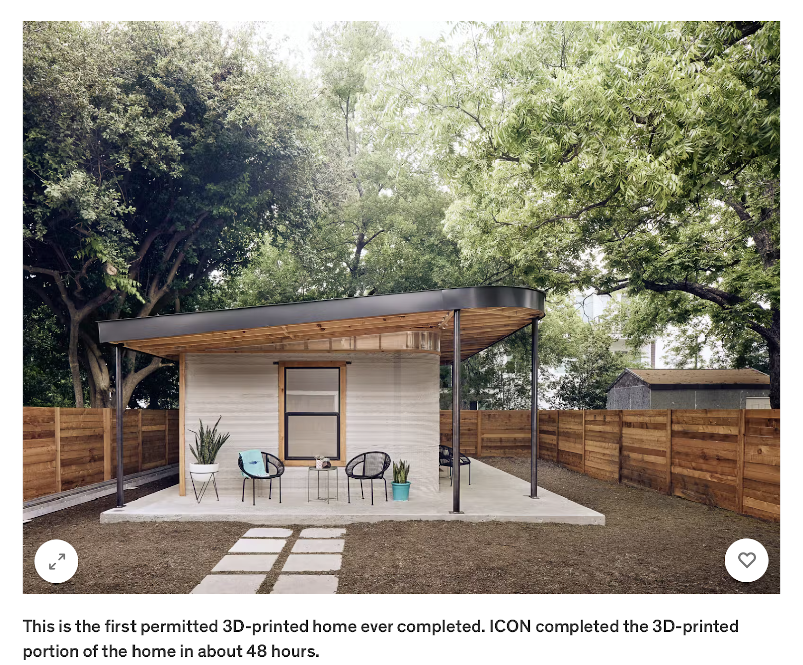
Source:https://www.dwell.com/article/icon-3d-printed-homes-for-4000-dollars-23d715bf

To make this solution even more cost effective, I started looking into ways to make the construction process even less expensive. That is when I found the idea of a modular design. I realized that building everything on-site can be expensive and slow, so instead, I plan to 3D print modular parts of the house off-site in a controlled environment. To further make the process simple yet flexible, I want to offer three modular units that are in different sizes the buyer can choose from. These units can be placed however the buyer wants within the set amount of space. If they want to reduce the overall cost they can take out one of the units. On the other hand, if they have a larger budget, they can add another unit. This system will make the design more flexible and will ensure that creativity and personalization be a prominent aspect of the build process.
Another benefit of using concrete as the main build material is its high thermal mass. Thermal mass refers to a material’s ability, like concrete, to absorb and store heat. When the temperature drops in these materials will release the heat they stored, this is beneficial as it warms up the living space naturally without emitting CO2. Concrete can store a lot of heat during the day wich is why its beneficial material. This property of concrete is especially beneficial for climates like Los Angles’s, which is known for its hot days and cold night.

Source: https://www.novatr.com/blog/modular-home-architecture
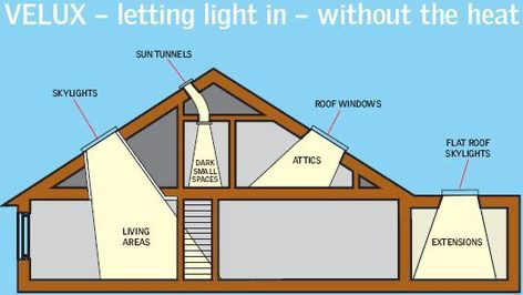
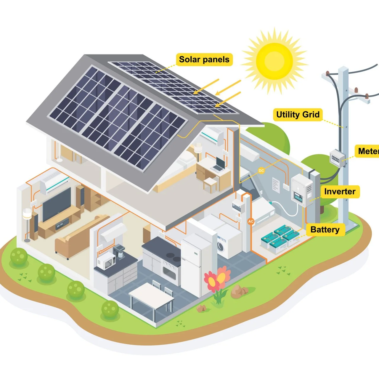
I also want to create a structure that is eco-friendly and reduce the use of fossil fuels for energy generation. To achieve this, I plan to make use of solar panels and skylights and install them in the home. The solar panels will allow the houses to generate their own energy using renewable energy, which will lower their reliance on fossil fuel consumption and decrease the Co2 emissions. The skylights will help reduce the use of energy consumption during the day by making use of natural light to brighten up dark spaces in the house, eliminating the use of artificial lights. Both of these features of the house will not only help the environment, but also make the homes much more affordable as it will reduce the expenses the people living there will spend on the energy bills.
source:https://www.pinterest.com/pin/444237950747782146/
Another important feature I want to include in these houses is wifi. This will play a huge role in empowering the chronically homeless individuals by giving them access to education, job training, and essential online resources. Homeless veterans will also benefit with the access to wifi as they will be able to telehealth services and VA resources and job training. The free wifi systems will be installed without making the homeless people pay extra for the house through government grants. Grants like BEAD ( Broadband Equity, Access, And deployment) will allow us to reach the goal of including free wifi. By integrating wifi systems directly into the house, it will enable lower-income people to become more independent and financially stable.
The Constraints
Constraint 1: House pricing
The first hurdle I needed to address is the issue of affordability. According to the National Alliance to End Homelessness, the average income for a homeless individual in 2022 was $6,934-$8,169, this means that buying a house with the current house prices never even crossed their minds. Additionally, the U.S census bureau stated that an average american spends 31.0% of their income for housing. This means we need to ensure that the amount the affordable house costs must fall in between this range, to be most accessible for them. This will allow for the rates of chronic homelessness in Los Angeles to drop as they are able to afford a house.
Constraint 2: Uneven land
As Sylmar is located in San Fernando Valley, it is known for its uneven land and hilly terrain. This poses a big challenge in placing modular housing units on the ground because the modular parts will be created on an off-site location and are all designed to sit on level foundations. Uneven terrain can lead to misalignment, which may cause the structure to tilt or become unstable over time, and might even become a hazard. A possible solution to this problem is extra excavation, grading, or custom foundation work. However, this would add extra time, complexity, and cost to the project, which goes against the goal of making the housing affordable. If the land isn’t properly prepared it can also cause installation issues and delay the setup of the modular units. The picture below shows the topographic map of San Ferando and it shows hilly terrain of the area. 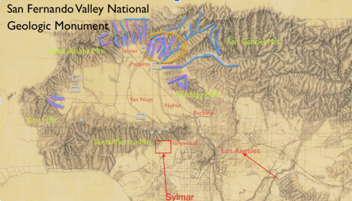
Source: https://valleyvillage.home.blog/tag/sylmar/
Constraint 3: solar panels issues
The one issue with solar panels is that when they are installed on traditional roofs, they are usually facing either east or west. This means that the panels will only get sunlight half a day, lowering their efficiency and causing them to generate less energy. To fix this problem, we would need to invest in more solar panels and install them on both sides of the roof. However, this would increase costs significantly, pulling me away from my goal of keeping our house affordable. The necessity of extra panels will pose a major issue in making the house affordable.
This image visualizes the constraint I explained above. As you can see, when the sun is on the right side, only the panels facing the direction of the sun are converting the rays and generating it into energy, while the panels on the opposite side are not generating any energy. This process is inefficient because not all the solar panels and limits the amount of energy that can be produced.
Source: https://www.linkedin.com/pulse/how-much-solar-power-do-i-need-my-home-aesha-desai/
Solving the Constraints
Solving constraint 1:
To ensure that the homes remain affordable for homeless and low income individuals, each buyer will start off with a medium sized, main unit, which is one of the three available types. Depending on their budget and needs, they can choose to add one or both units to the main unit. Buyers are not obligated to get all three units, allowing flexibility and retaining affordability.
The three types of units include: a large sized unit, a medium sized main unit, and a smaller unit that will include a bedroom and a bathroom. There is no fixed floor plan; instead, the floor plan will depend on the number of units and how the units are arranged.
An average lower-income household will likely only be able to afford the medium sized unit. Therefore, the unit layout will be designed to include all of the living necessities, like bathroom, small kitchen, and sleeping area. The pricing of this unit will have to fall within the affordability range of an homeless individual. According to the data from the U.S census bureau, an individual will at max spend 30% of their yearly income. Additionally, the data given by the National Alliance to End Homelessness indicates that the average amount a homeless individual will spend on a house will be $2,265.45. Unfortunately, the price of the house will exceed the $2,265.45 and this may put it out of reach for the homeless individuals. To ensure the houses are still affordable, I started exploring the internet for other ways to fund and cover some of the construction costs. That’s when I discovered governmental grants that support the construction of houses for the homeless. For example, the Homekey Tribal NOFA grant has a funding of 75 million dollars, with the purpose to help individuals experiencing homelessness or at risk of homelessness. By applying to this grant, the funds received will pay for a portion of that funding which will lower the expenditures on the house. By combining external funding and cost effective construction techniques, the prices of the house will be brought back into the $2,265.45 price range, making it more accessible.
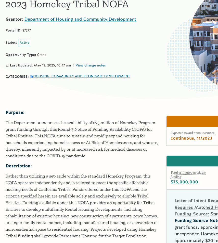
Source:https://www.grants.ca.gov/grants/2023-homekey-tribal-nofa/
Solving constraint 2:
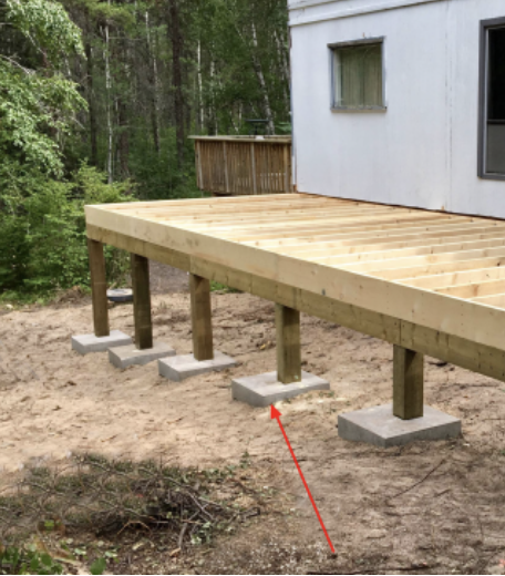
Uneven land in Sylmar is a major issue as explained above, and one way to solve this is through custom ground preparations. However, as explained this can significantly increase costs, and any possible mistakes can lead to misalignment. After some extensive research, that's when I came across the practice of using posts to elevate the structure and level it out. As you can see in the image below blocks are placed under the whole house structure and elevate the house and try to level it instead of trying to dig and increase the labour work. However, the issue with using traditional concrete blocks to level it out a structure is that they can lack precision, have higher labour costs, and they do not have any flexibility post-installation.
The idea of elevating the structure above the ground to level it out was fascinating, and to avoid the issues that there are with the traditional methods like using concrete blocks, I decided to custom build my own posts. These posts will be easy to install, require very little labour, and can easily be adjusted even after installation through remote access. They will also be created out of durable materials, yet low cost, ensuring long term stability and support for the modular units on uneven land for long periods of time.
Solving Constraint 3:
Solar panels on traditional triangle roofs can be inefficient, because they aren't facing the run at all times, which means they can’t generate the maximum amount of energy throughout the day. Yet, solar panels are necessary, as they generate free energy, which can reduce the energy bill, and reduce the reliance on fossil fuels making the house more Eco friendly. To solve the issue with solar panels on traditional roofs, the houses will have a nearly flat roof. The roof isn't made completely flat because the water still needs to flow down. The intention behind flat roofing is, so that we can attach a custom solar tracker which is cheaper and just as efficient. This system will allow the solar panels to adjust based on the sun's location in the sky and always point towards it. This will extinguish the inefficiency of the solar panels as it will now be able to maximize the amount of energy that can be produced in a day.

Source: self drawn
Putting Our Ideas on to Paper
Now that the research and the planning phase is complete, we can start putting our ideas on paper. The supplies you will need will be:
- Ruler
- Pencil
- Eraser
- paper
When having paper references it makes the process of CADing much easier, because then you can visualize the design details and make calculations based on them. Make sure to use a ruler so that the lines are straight and the drawing looks clean and accurate.
A) Steps to draw a rough look of the first unit:
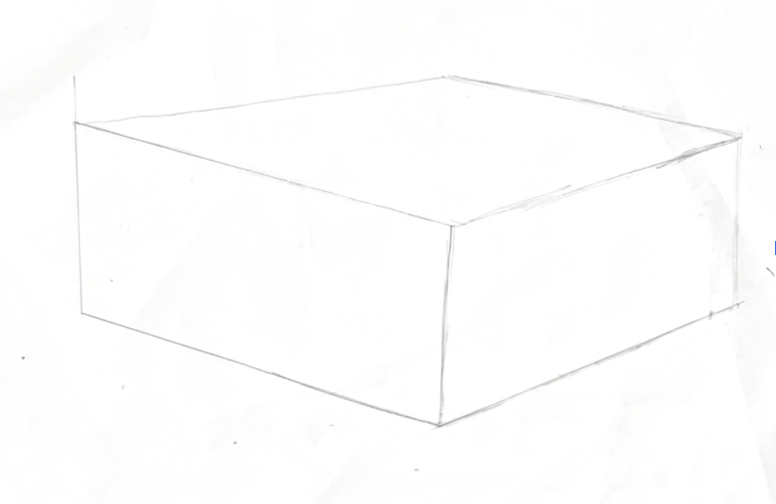
Make a rough sketch

Drawing the details

Add the dimensions
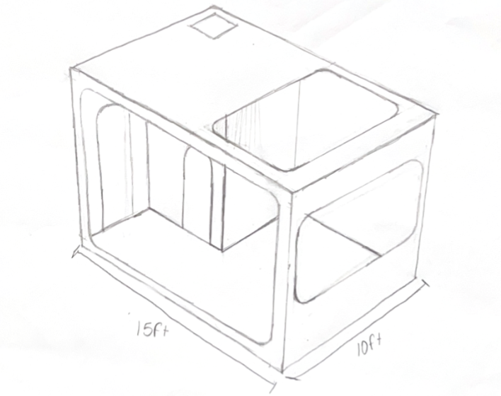
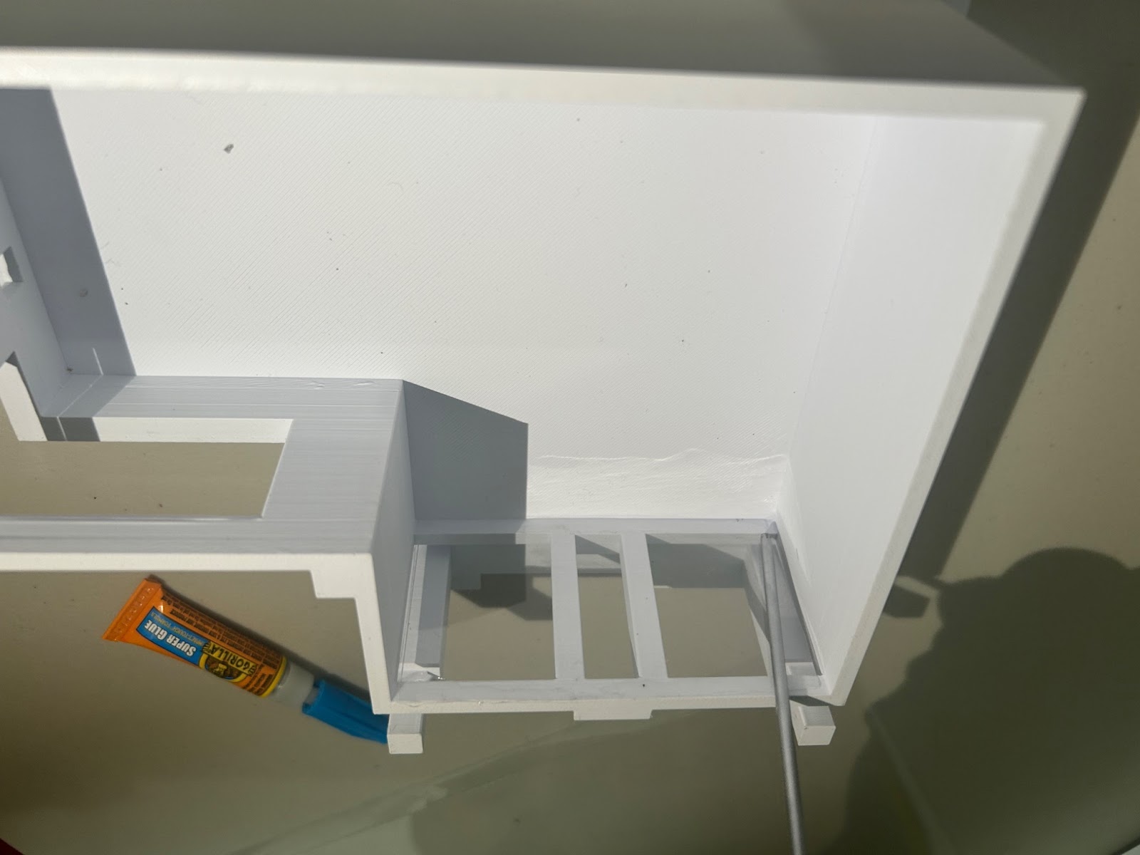
Here is the first modular unit, its floor plan will stay the same, as it will only contain a bedroom and a bathroom. The unit’s size is about 150 square feet, which means it is 10 by 15. The structure has three extrusions on the hidden face. These extrusion are designed to connect two modular units together.
Something like this:

B) Now moving onto the steps to draw the rough look of the second unit:
Create the general shape of the structure
Draw in the details of the structure

Add the details

sdd the dimensions
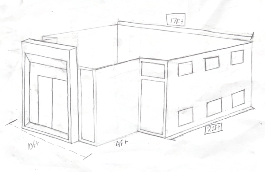
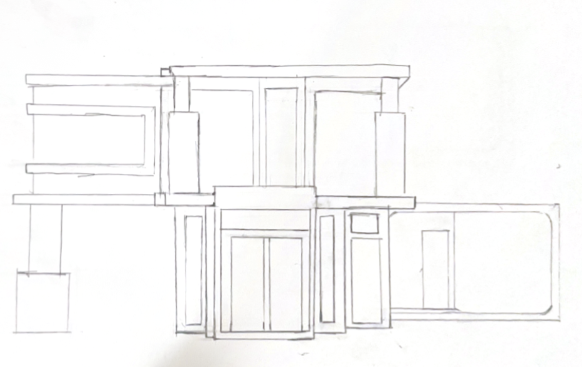
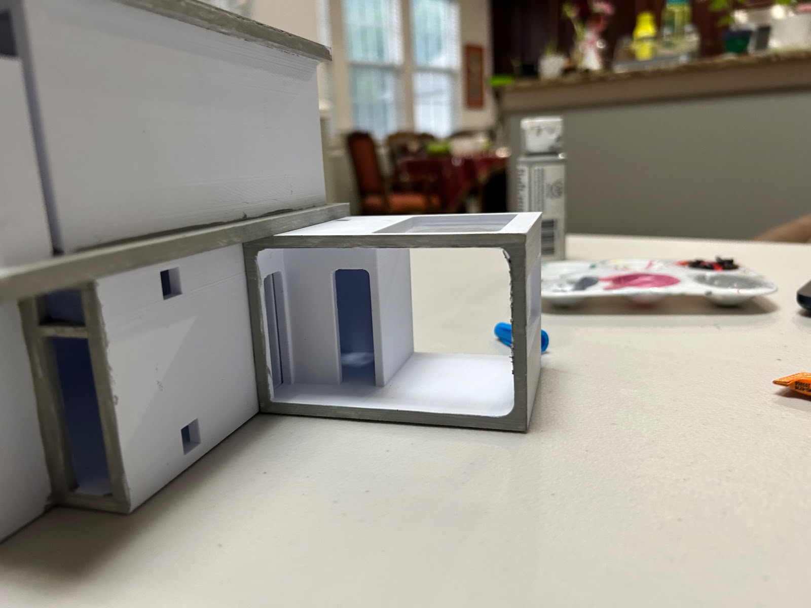
This unit is the main unit, which means the buyer starts off with this unit and can add on the other units to add more space. This unit does not have a fixed floor plan, it will be decided later based on the buyers preference. However, the front of this unit will always stay the same, presenting a fixed front door and front windows as shown in the model. The main unit also serves as the main entrance to the house. The placement of any additional doors or windows on the remaining three walls is entirely up to the user’s preference. The 6 cube cut outs on the side of the unit may look like windows, but they actually serve as connection points between units, which will allow the units to become one unified structure. The insertion points are located on all three sides of the unit, which will allow the structure to expand by connecting other units. While the cutouts are not being used they can serve as mini windows, allowing the sunlight to pass illuminating the place and reducing the use of electricity. They can also be switched out for normal windows and doors when not in use. The size of the main unit is about 400 square feet.
C) Finally, we will move on to the third and final unit.
First create the general structure of the unit.
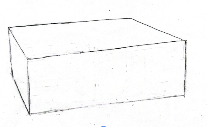
Add the external details

Add the dimensions
This is the last unit out of the three units and it is also the biggest, coming at about 540 square feet. This unit does not have a fixed floor plan, but it does have a fixed front design. It can be placed as the second floor or can be another extension of the first.
All three of the modular units are designed to have multiple windows to maximize the amount of natural light to enter, thereby reducing the total energy consumption. These units are easily customizable and also incorporate a passive climate control design. Additionally, they are intentionally designed for easy expansion and feature a reliable connection mechanism, which will allow seamless connection to another unit if required.
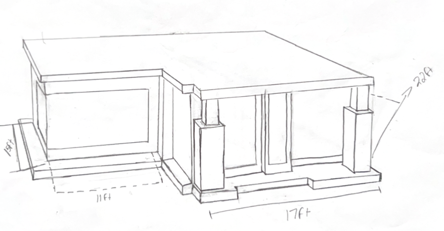
Arrangement of the Modular Units
Now, we need to design the arrangements of the modular units. This step is crucial, as it will serve as a proper reference during the cad process, this will ensure we have a well structured design. The requirements for the arrangement are to place the third modular unit as the second floor, and to connect 1st module to the main module.
The arrangements will look something like this:
This configuration of the house incorporates all three modular units in its designs and gives a clear idea of their potential arrangement. The pillars are added to increase the structural integrity of the second floor.
Bringing Our Ideas to Life Using Fusion
Now that all the ideas are put on the paper, we can start bringing the designs to life using the power of CAD. For this project, the software we will use will be Fusion 360, it’s a software created by Autodesk. Fusion is known for its extremely smooth CADing experience and its user-friendly interface.

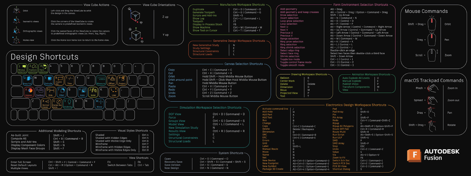
Learning Fusion 360 wasn’t too complicated, especially because my previous experience used another Autodesk software called ThinkerCad, along with other CAD softwares. While I still had to learn some of the new tools and their shortcuts by watching a bunch of youtube tutorials, the process was still enjoyable and helpful. Autodesk also offers a web page with a downloadable desk mat which lists all the Fusion 360 keyboard shortcuts. This resource was especially helpful as I was getting familiar with all the shortcuts.
Autodesk desk mat:
The simulation feature of Fusion 360 was the most interesting and useful part of the software. It allowed me to test and identify problems of my design without actually bundling the structure making the process much more efficient and simple.
These are the youtube videos that used to get familiar with fusion 360:
Fusion 360 Complete Guide - MADE EASY 2024 Simulation for Absolute Beginners — Fusion 360 — And Your Comments & Questions— #LarsLive 61
Design First Modular Unit on Fusion
Lets begin with the first modular unit, as previously stated this modular unit will have a fixed floor plan that cannot be altered by the buyer.
We will begin CAD process from the side view of the structure

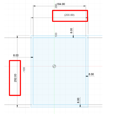
First, create a rectangle with a measurement of 10ft by 15ft, as each of the modular units will have a total area of 150 ft.
This is the tool you will use to create a triangle, and the shortcut for it will be ‘r’:

You can adjust the length and the width of the rectangle or any structure by using the shortcut ‘d’ to activate the dimension tool, then entering the desired measurements. You can click the surfaces you are trying to adjust after clicking ‘d’. If it's difficult to remember all the shortcuts you can find the dimension tool on the taskbar above.

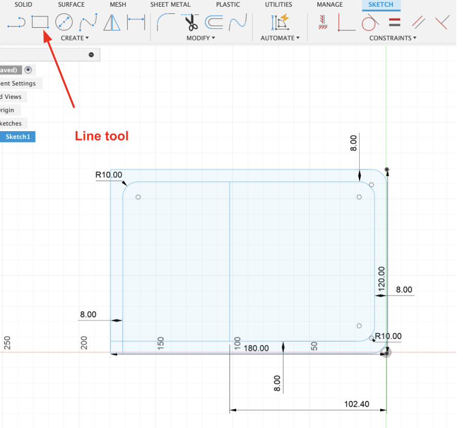
Next, create a second rectangle inside the first one, leaving a gap of 8 inches on all four sides. This will create a consistent wall thickness around the parameter of the structure.

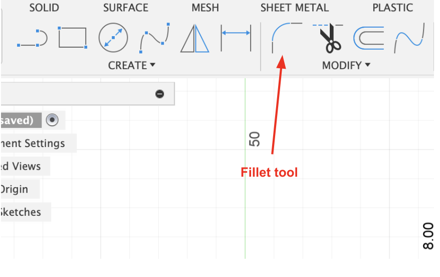
Apply fillets to all four corners on the right side of the structure. Then, fill the top left corner of the interior rectangle.

To use the fillet tool, you can use the shortcut ‘f’ or you can access the filet tool from the taskbar above:
- Next, using the line tool create a line that is 102.40 inches away from the right side of the structure.
- Now you can finish the sketch, using the keyboard shortcut ‘e’ to activate the extrude tool. Select the 8 inch gap between the two rectangles we created while sketching, and extrude it to create the walls.

The extrude distance should be for 10ft (120 inch).

- Now we will create the interior walls of this modular unit.
a) Now, we will extrude the left side of the line we drew through the approximate center of the sketch for 8 inches.

b) Then proceed to create a new sketch at the floor of the structure.

c) Then, draw two rectangles which will represent the interior walls. The thickness of both rectangles will be 7 inches, as the interior walls do not need to be as thick. The first rectangle begins from the edge of the back wall, and has a length 75.5 inches. The second rectangle should begin from the left wall, positioned 38 inches away from the front, and should have a length of 62.6 inches.

d) Once completed, extrude the two rectangles for a distance of 104 inches.

e) Lastly, create a new sketch on the face of the extrusion of the second rectangle. Then, create a rectangle 7 inches away from the edge of the end. The rectangle should have a width of 27 inches, and a length of 74 inches. Finally, fillet the top two corners of the rectangle with a radius of 5 inches.
Continue by extruding the created doorway. Use the “cut” tool and extrude -7 inches.

From here we can work on all the exterior details of the modular unit.
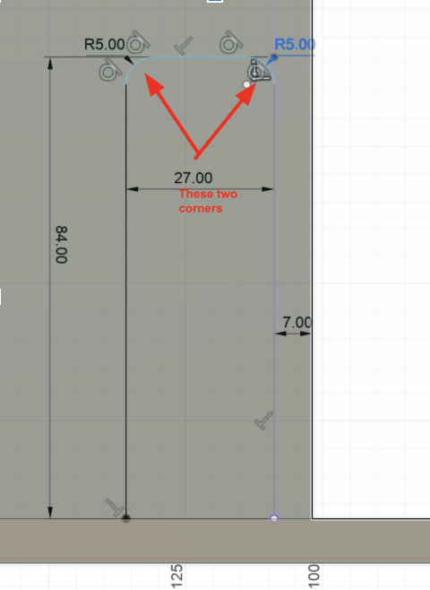
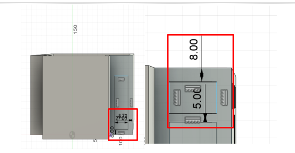
Create a sketch on top of the right face of the structure, and then create a rectangle 8 inches away from the bottom and 8 .5 inches away from the right. The length of the rectangle should be 84 inches and the width should be 27 inches.

Now, fillet the top two corners of the rectangle with a 5 inch radius.

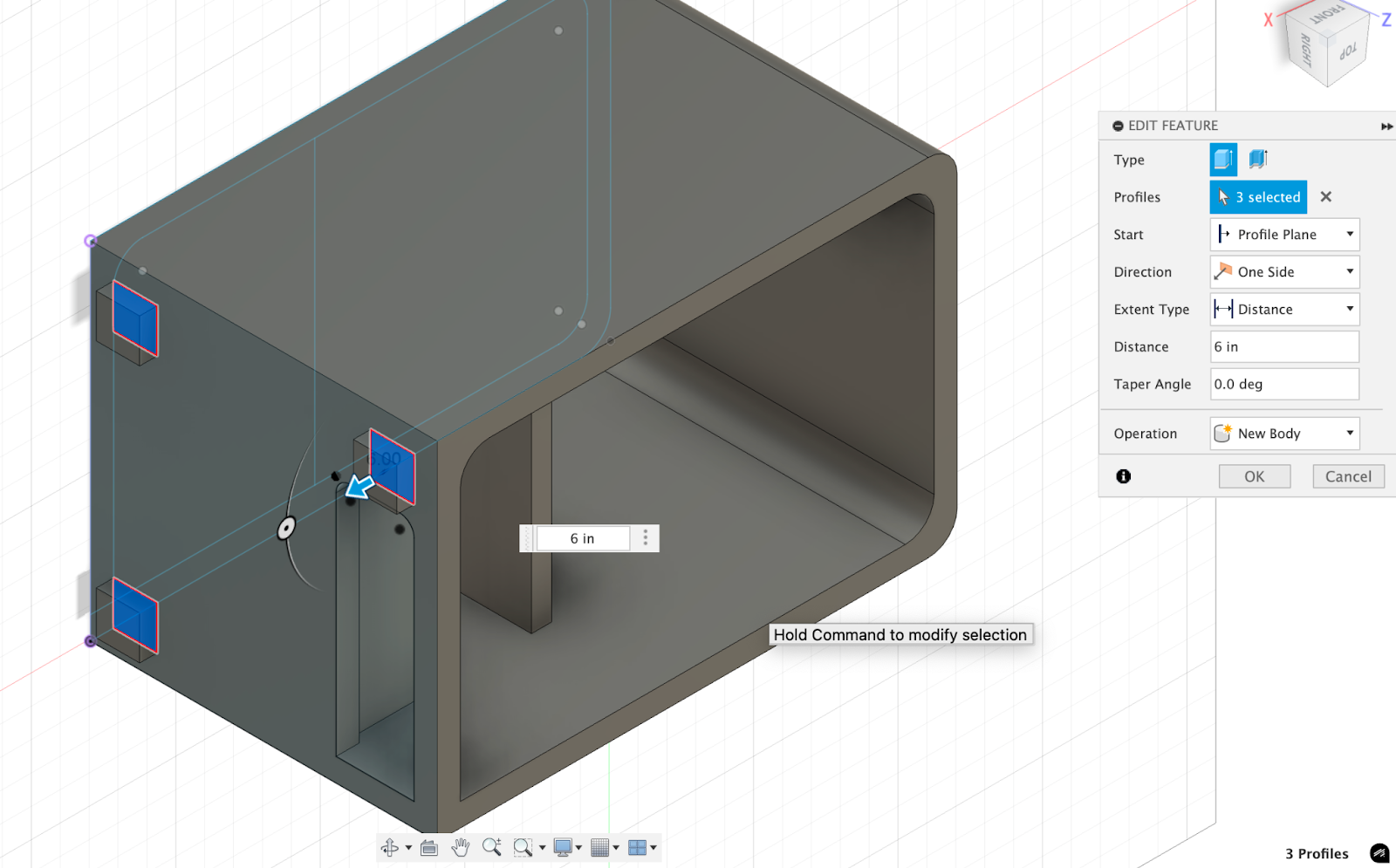
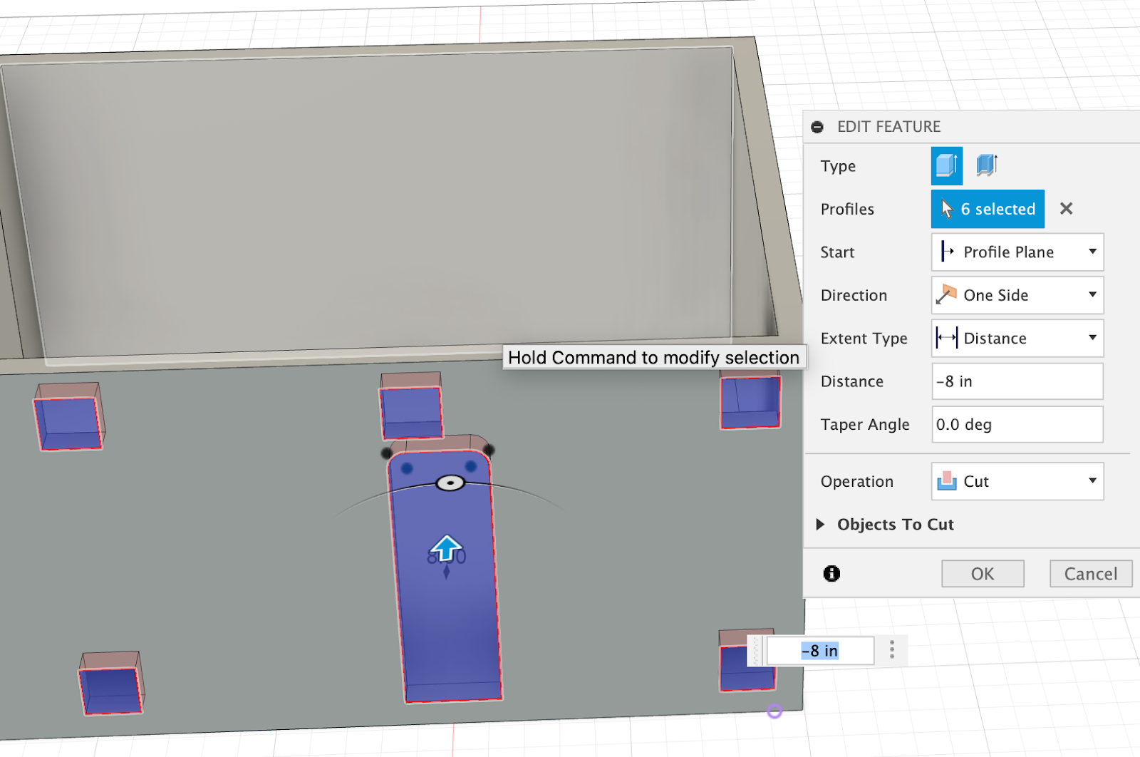
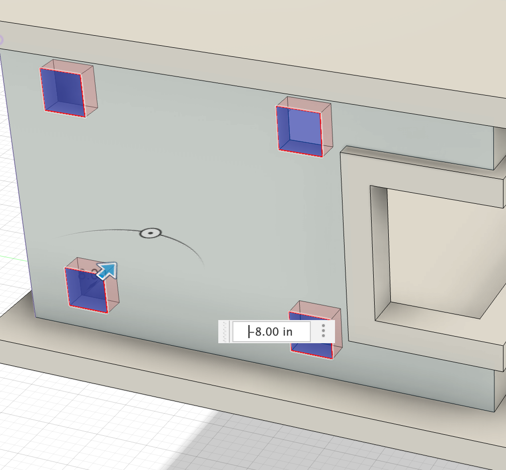
At this point, we will create the connection points on the structure so that it can seamlessly join with the other modular units. On the same sketch from the previous create three 15X15 squares on the three corners of the face. Each square square should be positioned 8 inches away from the edge.
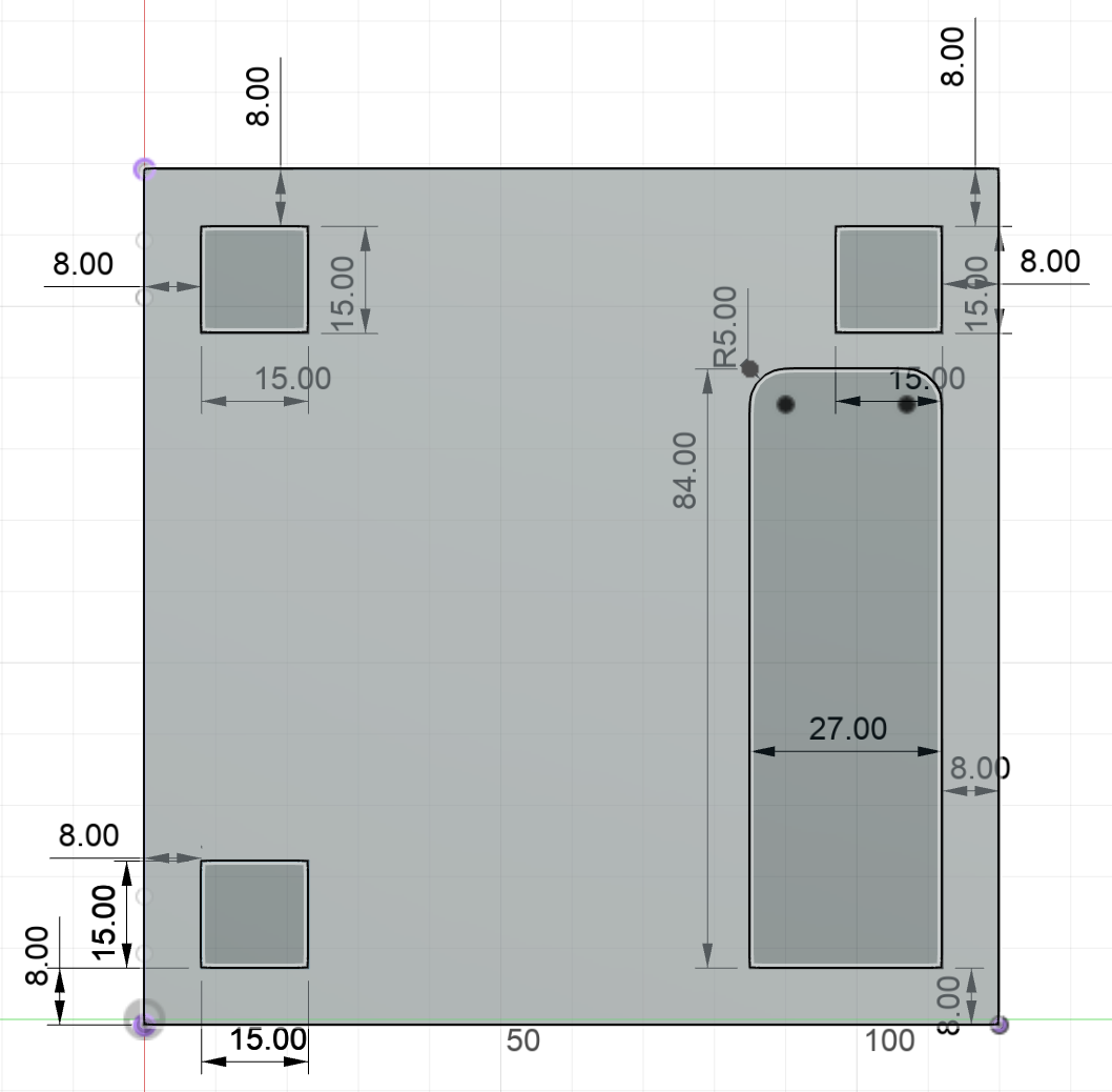
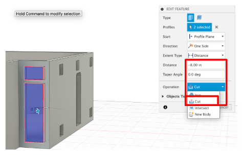
Extrude everything on this face. First extrude the door, by clicking the “cut” option and extrude for a distance of -8 inches. Finally click “ok”.

Activate another extrude, and select “New Body”, and extrude the three squares for 6 inches. We choose “New Body” rather than “Join”so that the new extrusions can later be combined with another structure. These extrusion points serve as the connectors, allowing the two units to have a clean attachment.
Create another sketch on the top face of the structure. Create two rectangles. For the first rectangle, make three of its sides 6.5 inches away from the edge. For the second rectangle, make it a square that is 13X13, and it should be 21 inches from the left edge and 25 inches from the bottom.
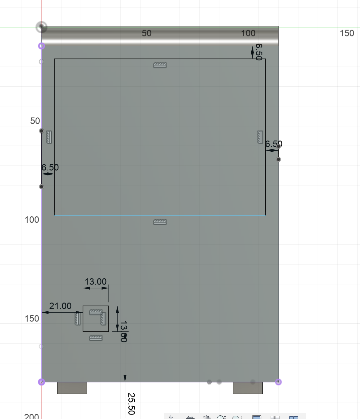
Fillet the four corners of the rectangle and the square with a radius of five inches.

Activate the extrude tool and click the “cut” option, and change the distance to -8 inches. Extrude the rectangle and the square, this will create two skylights. A small one for hte bathroom.

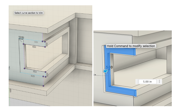
Finally, create a sketch on the right face of the structure. Then, create a rectangle that is 6.25 inches away from the right and left edge, and 17 inches from the top edge.

Click the extrude tool and in the “operations” sections click the “cut” option to extrude the rectangle for -8 inches to create a window.

Lastly, fillet the four corners of the rectangle with a five in radius.

The final structure will look something like this.

Design the Second Modular Unit
Let's begin with the second modular unit. This unit does not have a fixed floor plan, so unlike the previous unit we don't have to create any interior structures.
Start off by creating a sketch on the xy-plane, and adding a rectangle. The length of the rectangle should be 17ft, while the width should be 21ft giving a total square feet of 357.
Create another interior rectangle, and ensure that it is 8 inches away from each side.

Now, create an addition to the structure created above by making another rectangle with 8 inch interior walls. Next, add another small rectangle that is 16X90.

Finish the sketch, and using the extrude tool extrude the 8 inches of space between the edges of the two rectangles for 10 feet.

Now that you have extruded that area, activate the extrude tool again and extrude the interior rectangle for 8 inches.

Lets start designing the house, we will begin with the front of the house.
- Create a sketch on the front face of the structure to draw the entrance. The rectangle should be 8.7 inches away from the right wall and 8 inches above the ground, this much space is necessary, even though the wall is 8 inches. We don't want the door to cut into the wall. The door is 27 inches wide and 72 inches high. Then, create a rectangle that is 50 inches high by 27 inches wide. This is called a “Transom Window”, they are used for ventilation and allow light into the room.
Using the extrude tool, click on the drop down and select “cut” and then click on the face of the door and the Transom window.
Extrude the rectangle at the front of the house, which was created in the first sketch, by 138 inches. In the drop down for “operation” select the “join” option.

Using the sketch tool create a sketch on the front plane of the extruded part. Then, create a rectangle that is 90 inches high and is 4inches away from the edges. Now, extrude the sketch, in the operations drop-down click on the “cut” option. Using the chamfer tool, chamfer the top face of the “cut” by 18 inches. Then, use the fillet tool to round the interior edges of the opening, the fillet should have a radius of 2 inches.
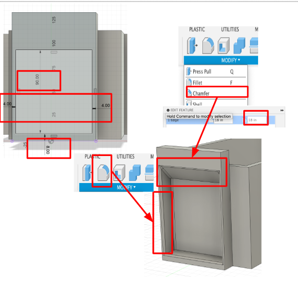
Filleting here is crucial, because it significantly improves the structural integrity by distributing the weight and stress. When there is a sharp change between two surfaces, it creates an abrupt shift in stress, which can lead to cracks and deterioration of the structure over time. We used it here because the ceiling has less supports and that means there is a lot of stress being put, that is why we need to dispute them evenly and have smoother changes in stress areas.
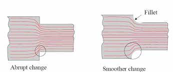
Source:http://catarina.udlap.mx/u_dl_a/tales/documentos/lim/albores_b_mi/capitulo5.pdf
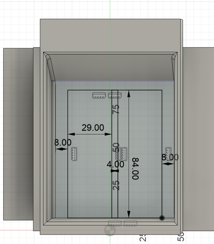
Create a sketch, using the sketch tool create two rectangles that are 84 inches high and 29 inches wide. The two rectangles should be 4 inches apart and 8 inches away from the wall on both sides. Thereafter, using the extrude tool “cut” the rectangles created in the previous sketch.
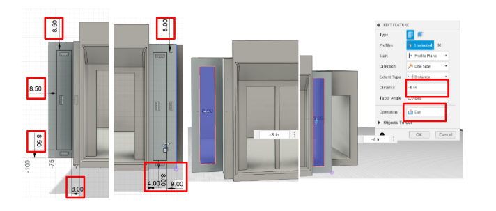
The last thing we have to do in the front of the habitat is to create some side lights. Create two rectangles one on the left and one on the right. The left side window should be 8.5 inches apart from the top and bottom, and from the sides it should be 8 inches away from the right edge and 8.5 front he left. Now for the right window, it should be 8 inches apart from the top and the bottom. And from the side it should be 9 inches away from the right side and 4 inches from the left. Finally using the extrude tool “cut” both of the rectangles created in the sketches.
Now we can move on to the right face of the structure.
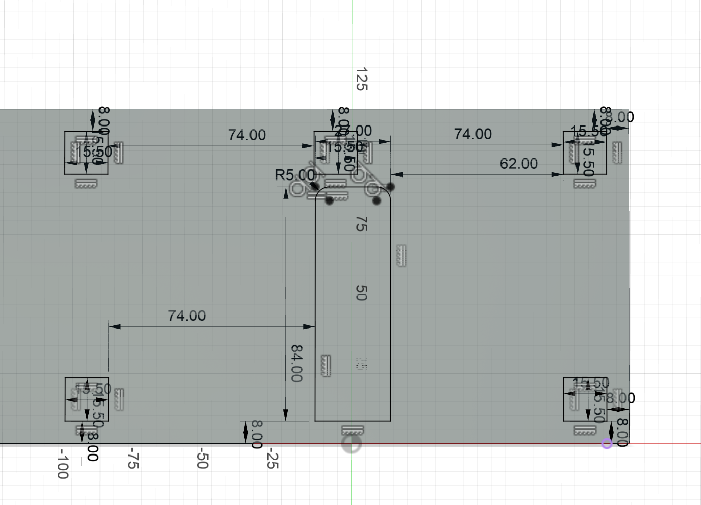
- Here, we will create the connecting mechanism that links the two modular units. Start by creating the sketch. In this sketch, draw five squares that are 15.5 by 15.5 inches, spaced 74 inches apart. Place two of the squares at the bottom of the structure, they should be 8 inches above the ground, and both squares should be aligned with the squares that are above them.
- Next, draw another rectangle which will be the entrance to the connected unit. This doorway follows the design we created earlier. If this house was designed and assembled differently, the door would not be placed here. The door is 84 inches high and 27 inches wide and it should be 8 inches above ground.
Finally, using the extrude tool “cut” all the sketches on the right face of the structure by 8 inches.
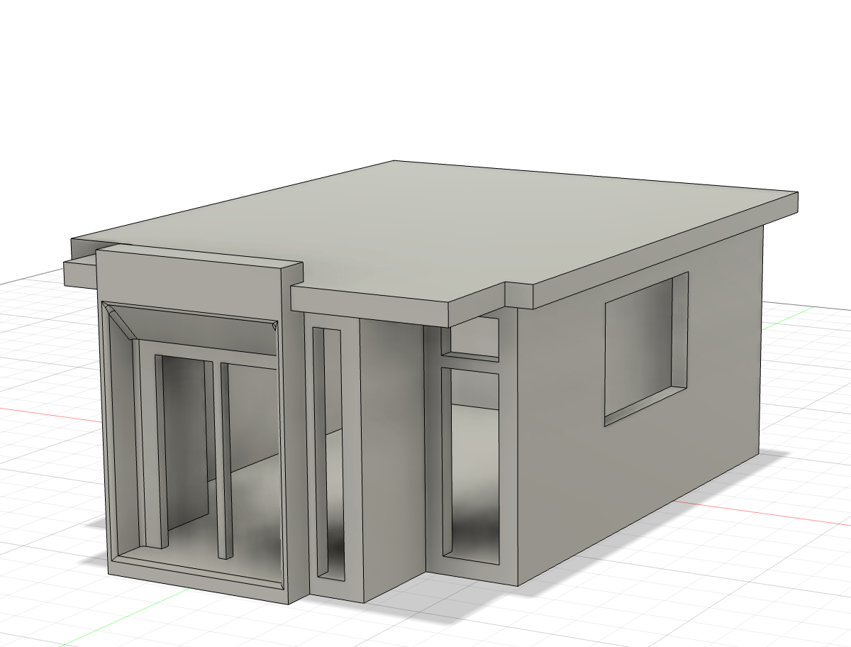
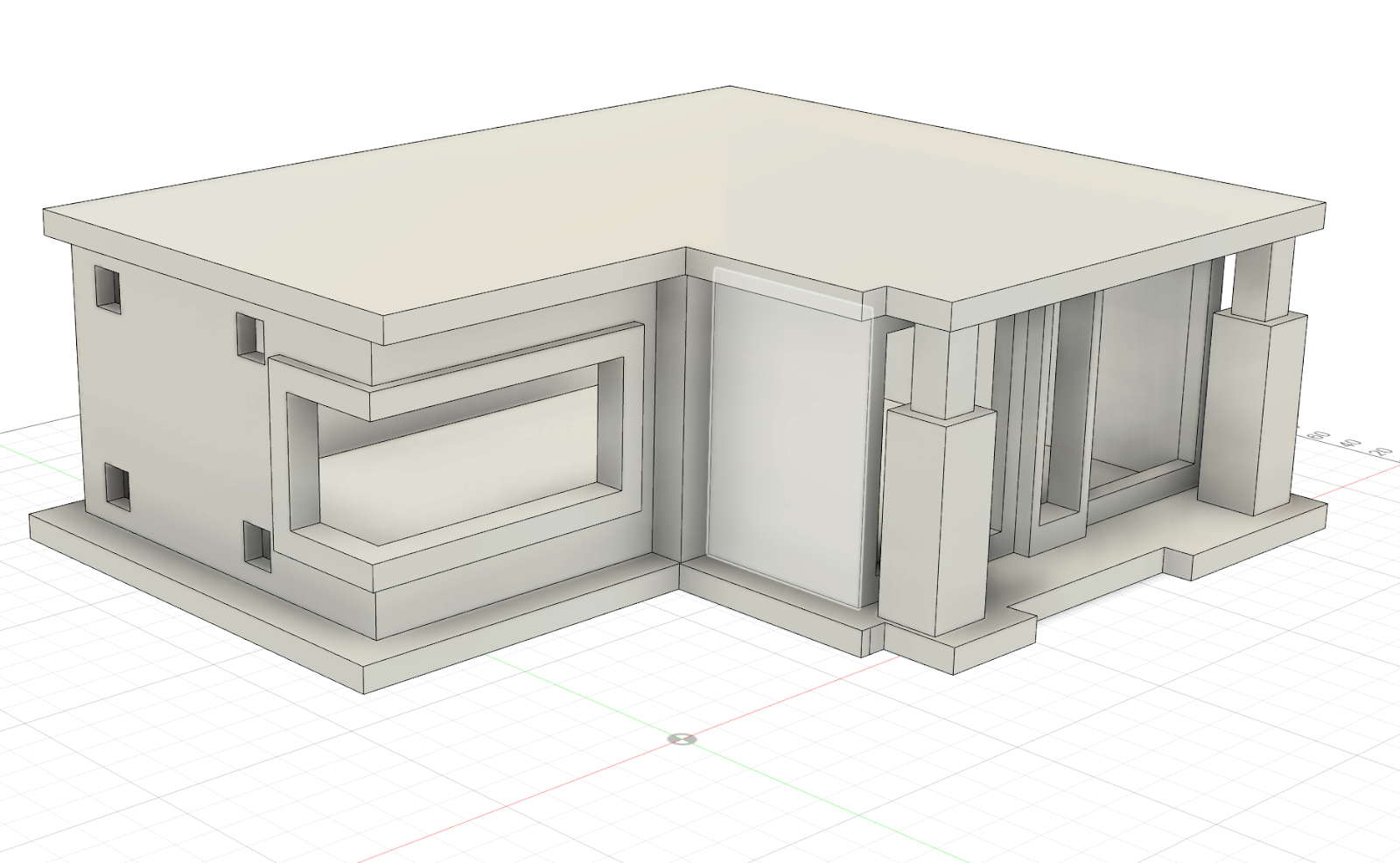
The final structure should look something like this.
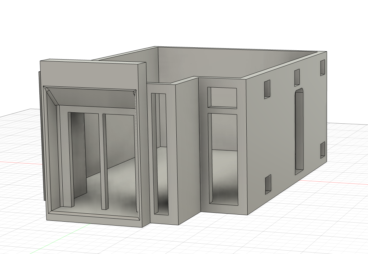
As stated in the beginning, this is the main unit, and it is designed to function independently as a home with roughly 400 square feet of living space. Most homeless individuals and lower income individuals will only be able to afford the main unit, as it will fall in this price range. Individuals that only buy the main unit of their house will look like this.
The Third Modular Unit
Finally, we can move on to the third and final modular unit. Although this unit is a separate structure, we will position it on top of the second unit temporarily to ensure the dimensions are aligned correctly.
- Start by creating a sketch, this sketch calls for two rectangles. In this assembly of the abode, the third unit is used as the second floor so we will have to create the sketch on top of the first body, which is also the main unit.
Extrude the sketch we created by 10 inches, ensuring the extrusion type is “new body”. This creates the third unit separate from the second.

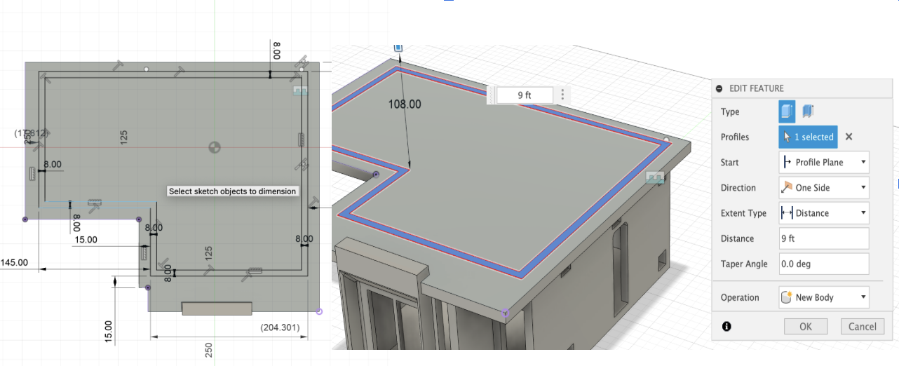
Create a sketch on the extrusion we just created, we will outline the wall of the unit. Set the wall thickness to approximately 8 inches. Position the back wall 12 inches away from the edge, and from the remaining sides, maintain a 15 inch offset from each edge. Next, extrude the sketch to a height of 9 ft.
Begin by creating a sketch on the front plane of the abode. On this sketch we will create the front windows of the third unit.
- First, draw two rectangles that are 69 inches wide, and keep the ends of the rectangle 10 inches away from the top and the bottom. In the middle, create a rectangle, this will be for an extended window. The ends of the middle rectangle should be 8 inches away from two of the other windows. Next using the extrude tool create the windows.
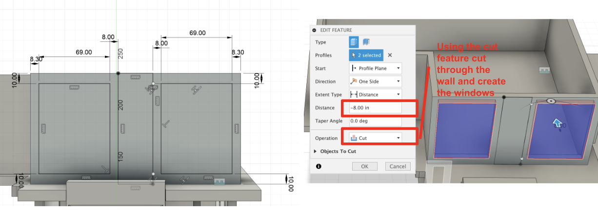
Using the extrude tool again, extrude the rectangle located betweeen the two windows for a distance of 7 inches. Next, start a new sketch on top of the extruded part. Using the rectangle tool, create another window, it should be positiond 5 inches apart from the two side edges and 10 inches from the bottom and top edges. Finish the sketch, cut the rectangle you created, which makes the window.

This design of the third unit calls for pillars int eh front of the house. Pillars are crucial as they provide essential support and stability to structures. Pillars are required here because the roofs are designed to protrude out and create an overhang, to support it and prevent it from getting damaged the pillars are placed there.
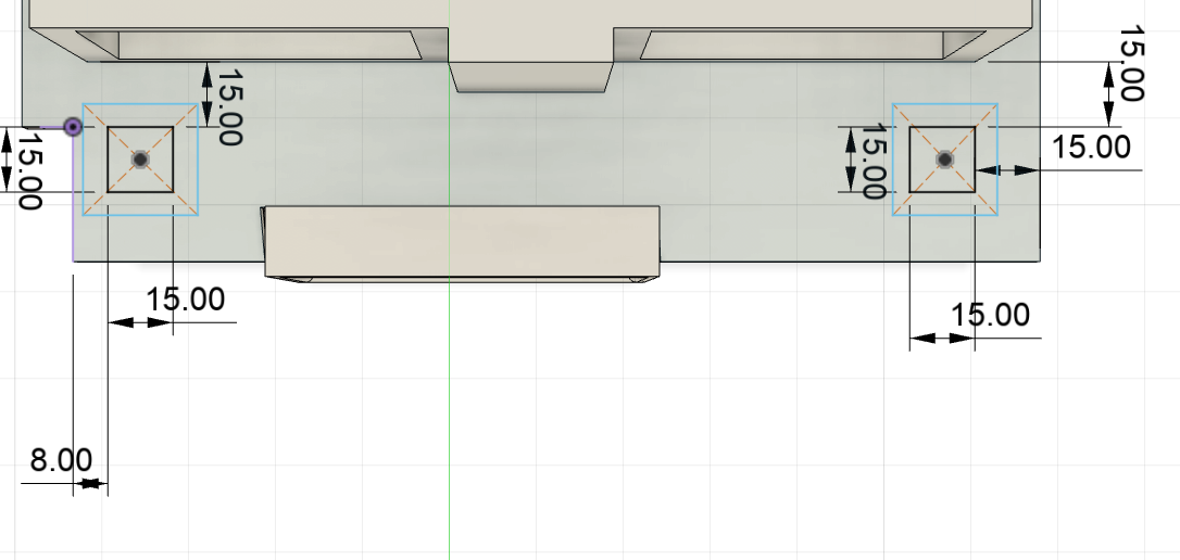
Create a sketch on top of the ledge which is on top of the main unit, here we will create the base of the base of the pillar. Create two small squares with a length of 15 inches, then around that square create another square using the center rectangle tool. We will use this tool as it will allow us to ensure that the square around the small square is precisely in the center. Make sure the square in the middle is 15 inches away from the edges.
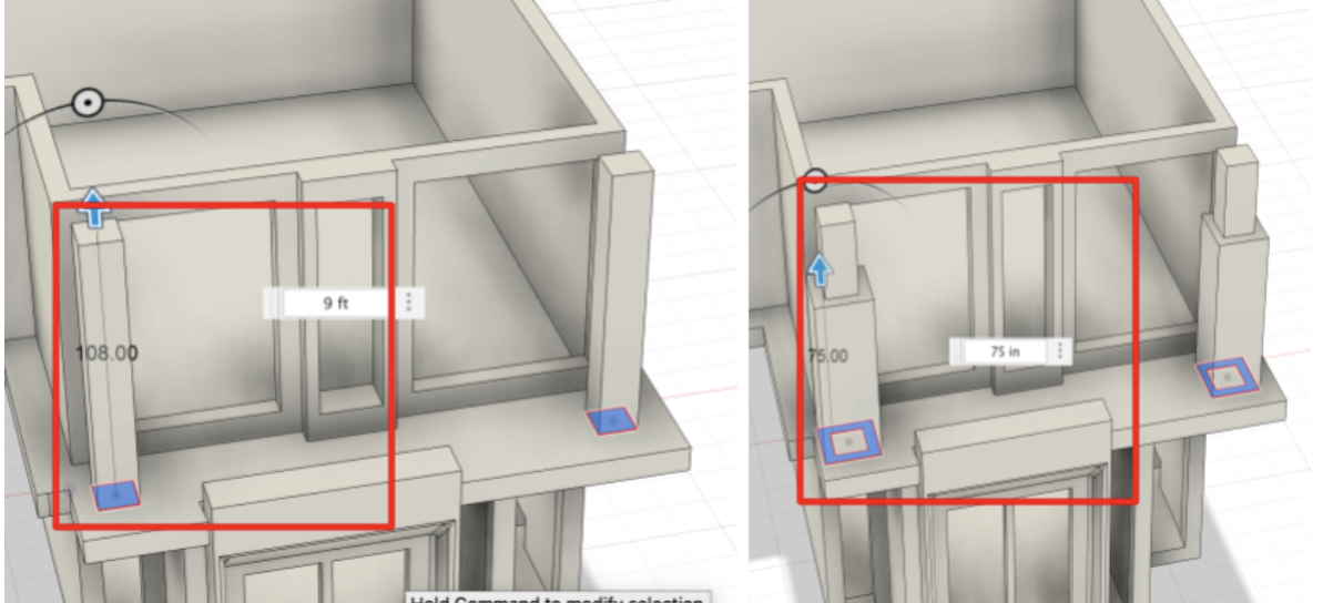
- First extrude the inside the square by 9ft. Then extrude the square that is round the smaller square by 75 inches.
Lets move on to the roof of the residence, the roof will be an outline of the structure of the second unit, however there will be some overhang. Overhang for roofs is crucial as it will provide shade during the summer and optimal sun rays in winter, reduces water damage, and increases it astetic appeal.

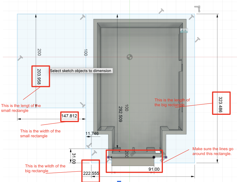
Create a sketch on top of the second unit. Next, using the line tool outline around the structure of the second unit. Use the dimension shown below to measure out the size of the roof. Then using the extrude tool extrude out the roof created for 10 inches.

Now we will move on to the side of the unit, where we will create the windows. The intention behind adding windows is that it allows light to enter the house, decreasing the reliance on energy making the house more efficient.
- On the side of the dwelling, draw a rectangle that is 120 by 70 inches, aligned with the edge of the left wall. Inside that rectangle, create another rectangle measuring 50 by 110 inches, also touching the left edge. Make sure the rectangles are spaced ten inches apart. Next, using the trim tool, present on the tool bar or by pressing “T”, which is its shortcut.

After finishing sketch, extrude the sketch we created by a measure of 5 inches.
Create a sketch on the left plane of the structure. Using the Line tool, outline the window, making sure a 10-inch gap is being maintained. Also make ure all ends of the sketch are closed so it can be extruded properly. Finally extrude the sketch for a distance of 5 inches.
Now, for the final step of this unit, we will create the connection points that will allow the buyer to add additional units later if they need extra space.
We will use the exact same measurements and spacing for the linkage area to ensure it is universal, allowing the modular units to connect seamlessly and without strain. Create four squares. These squares can be used connecting holes or as the connection points based on the need. In this case they will be available as the connection holes.

At last, using the extrude tool we can “cut” all the squares we created for distance of 8 inches.
The final structure of the third modular unit should look something like this:
Self Adjusting Solar Panels
The problem with traditional rooftop solar panels is their inefficiency, as they are unable to capture the rays of the sun throughout the day. To solve this issue, a new design was created that will overcome this inefficiency and maximize the amount of energy being stored through the solar panels.
- The solution involves attaching four linear actuators to a solar panel. This design enables the panel to continuously adjust its orientation towards the sun, ensuring it faces the sun at all times. The model below, gives an example of how the actuators will work and orient the solar panel towards the sun. The attachment on top of the linear actuator allows it to latch on to the solar panel.

Step 13: design the hydraulic press for the Solar panels on CAD
- To design the solar panel unit, we need to first design the actual solar panel.
- To make the solar panels I make use of the rectangular pattern tool that can be found in the tool bar. After using it I was able to create the solar panel.

- I wanted to make the CAD of the solar panel look more realistic, so I made use of Fusions’s appearance tool and was able to add color to the model. I was also able to change the material. This is what it looks like after the appearance was altered:
- The CAD model fro the linear actors for the solar panels.
- The whole unit.


The Code That the Pistons of the Solar Panel With Function On
https://drive.google.com/file/d/1_i-vX68pZ4r206GARUmxomfB8soopArB/view?usp=sharing
This code begins by using the geographical location of the house, which is provided through the input values for its longitude, latitude, and altitude, along with the time of the day. With this information, it calculates the sun's position using its azimuth and elevation angles. The system then aligns the normal vector of the plane formed by the four pistons with the direction of the sun. Using inverse kinematics it determines the respective height for each piston, so that the solar panel is facing the sun at all times. This process repeats itself at regular intervals, which enables the solar panels to track the sun throughout the day.
Draw an Explanation of the Posts
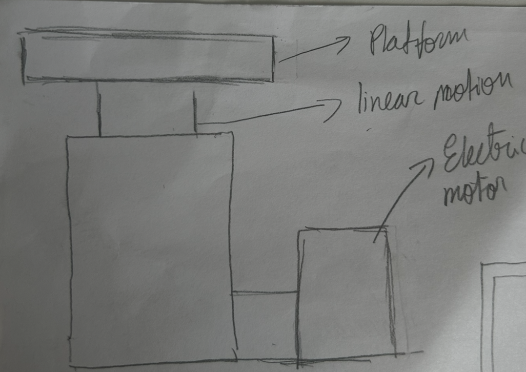
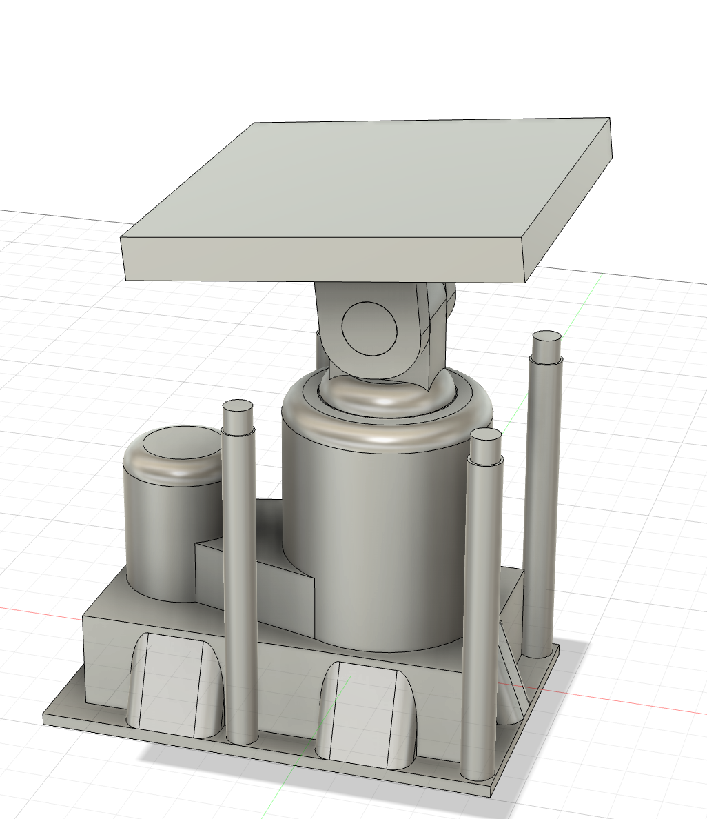
This is the linear actuator that will be installed under the house to elevate and level it out when the ground under is uneven. The actuator and lifting motor are designed to stay under the ground, while the lifting shaft extends upward to raise and stabilize the structure. This linear actuator is designed to be industry grade, meaning it can withstand up to 20 tons of weight. With multiple of them, under the house they will easily be able to hold it up.
Step 16: Designing the linear actuator in CAD
After drawing the reference page for the and figuring out the requirements I was abel to create the CAD model for the linear actuator. It looks like this:
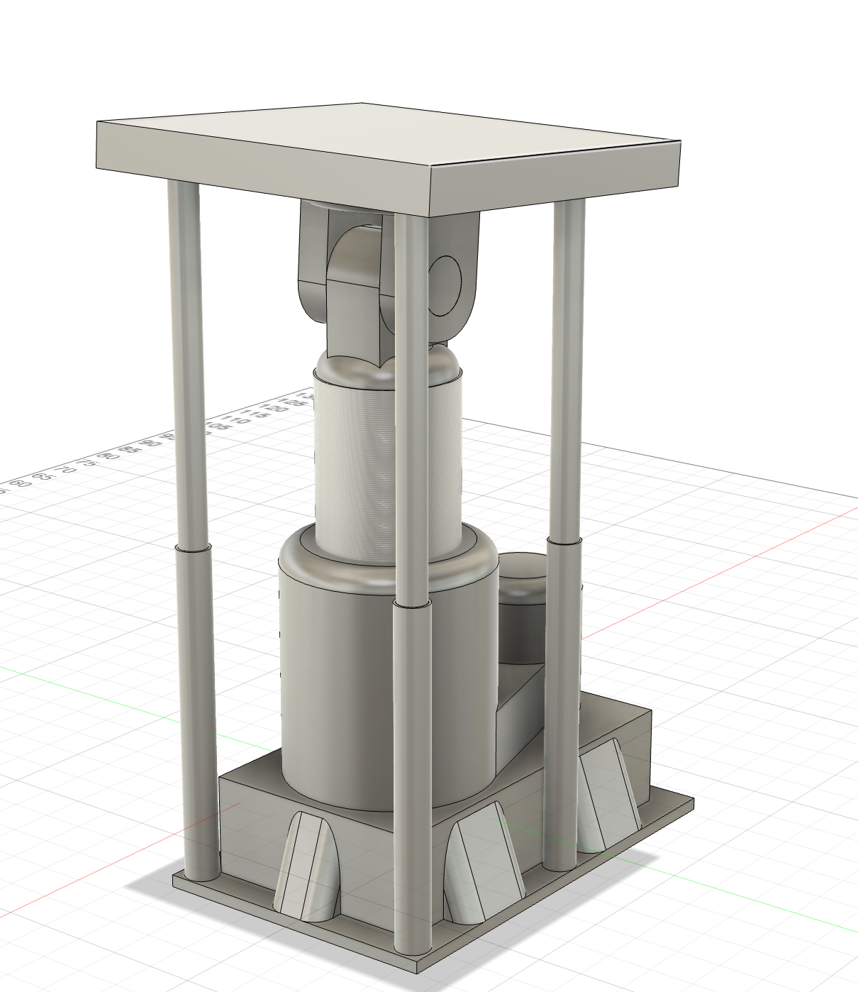
The support poles on all four sides were added after I conducted some further, where I found out that over long periods of time linear actuators will gradually lose height. To address this issue, these poles were designed to be adjustable. Once the actuator reaches its desired height, the poles can be extended and secured in place, preventing downward movement of the actuator ensuring the structure remains leveled.
Assemble All the Part in CAD and Show and Example
Now that we have designed all the parts we can put them all together on cad:
In this model, the house is assembled on an uneven surface, and the linear actuators are positioned and adjusted to level the structure. This setup simulates how the house would function with the actuators in a real-world scenario. Additionally, covers have been added to conceal the actuators and maintain a seamless connection between the house and the ground. The designed solar panel units can also be seen mounted on the roof of the house. Each panel generates approximately 250 watts of power, and with a total of 10 panels, the system can produce enough energy to operate the house with minimal reliance on external power sources.
Rendering the House
To gain a clearer perspective of how the house would appear in real life, the CAD model was rendered.


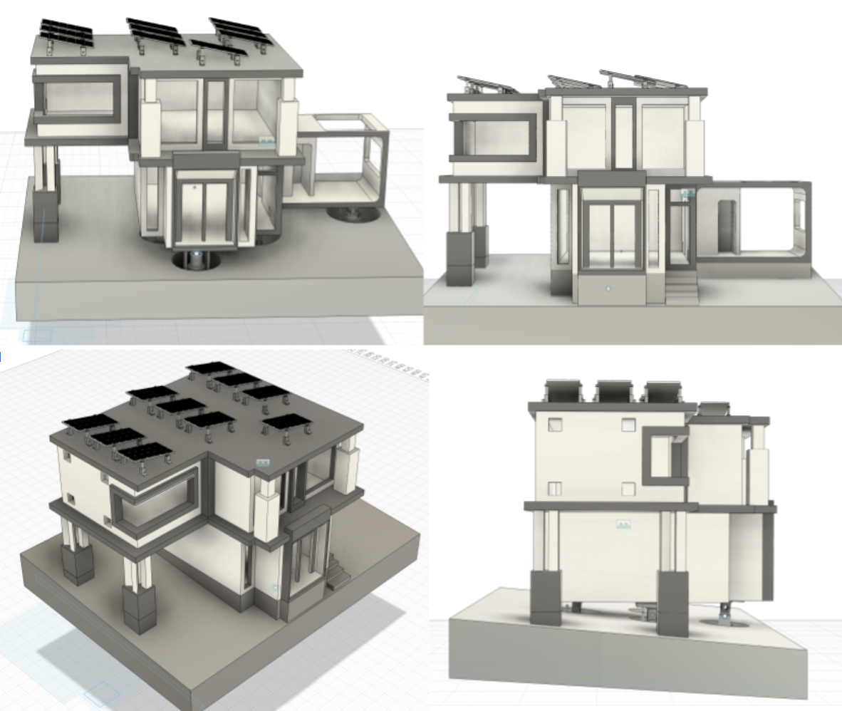
Possible Layouts of the Structure
To provide a clearer understanding on how the different layouts appear, a couple examples are presented to illustrate the possibilities beyond the current design.
- This layout features just the main unit and is considered the homeless friendly model, as it will fall in the price range that is accessible for them. In the area provided in this layout, it will consist of all the essential necessities a person needs to live in a home (kitchen,bathroom, and sleeping area).
Another possible layout includes the combination of the main unit and the first modular unit. This layout increases the total square footage of the house by 150 by incorporating the second modular unit. However, this addition of the second modular unit raises the price of the abode, placing it outside of the price range of homeless and lower income individuals.

One last example includes the main unit and the second modular unit being used as the second floor. The pillars are attached to increase stability and structural integrity. This model is another way we can attach the modular units together. Like the previous model, this model’s cost will exceed the price range of homeless and lower income individuals.

Bringing the Designs to Life
- Rendering the habitat offered a glimpse of how the house would appear in real life. However, to gain the full perspective, creating a physical model will fulfill this purpose. Instead of using other ways to construct a physical model, I believe 3D printing the model is the most viable option to give the best perspective. I wanted the model to be a 1:50 scale model of the CAD model. This size will be the best fit to give the best understanding. I was able to borrow my robotics team’s Bambu Lab P1S to print all of the modules of the house. I exported each of the parts from fusion in a .stl or .step file type. I imported each of the parts into the Bambu lab slicer, where I was able to scale it down using the scale tool.
- Importing the 3rd modular into the slicer.
- Importing the 1st module and the main module. With supports.
- Importing the roof and the enlarged solar panel.


Printing the Parts
Each plate’s print time ranged from 3-7 hours, making the total print time for the house 18hours.
Printing the third modular unit.

Printing the 1st module and the main module
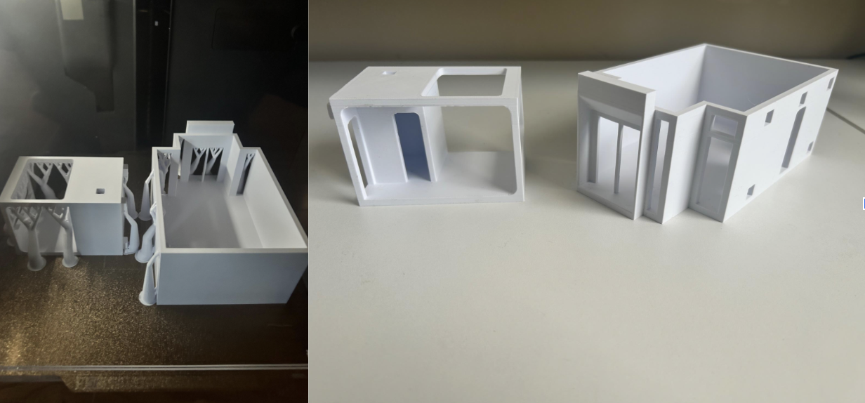
Printing the roof and the solar panel.

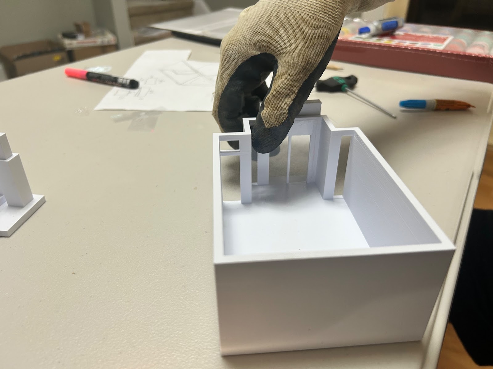
Step 25: Gather All the Parts Together

Now that all the parts have been printed, begin the assembly process. The parts required are the roof, the first module, the third module, the main module, and the two pillars.
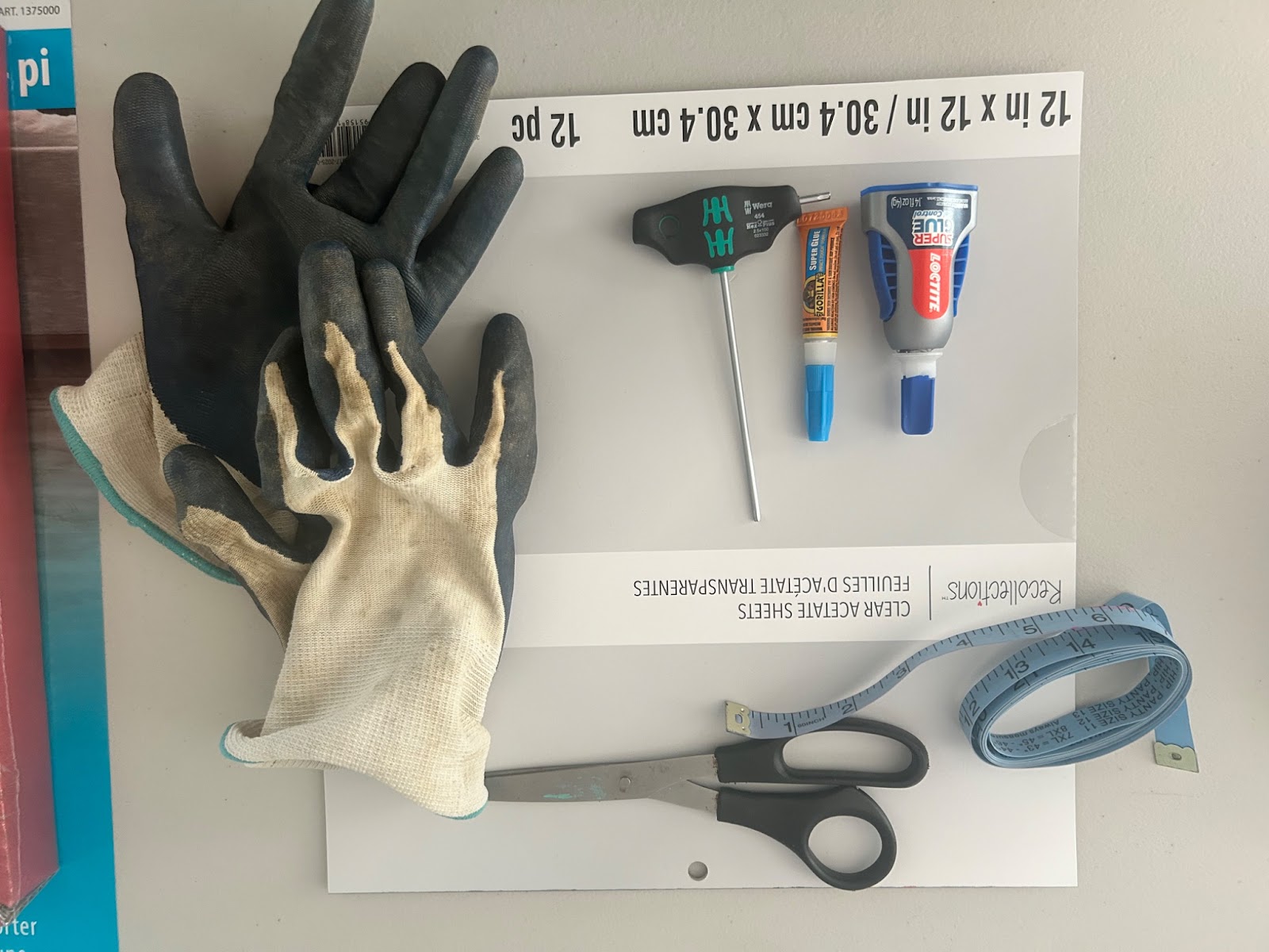
Supplies Needed to Put Everything Together
The supplies that you will need to benign the assembly process are:
Materials :
- Gorilla glue
- Locktight super glue
- Clear Acetate Sheets
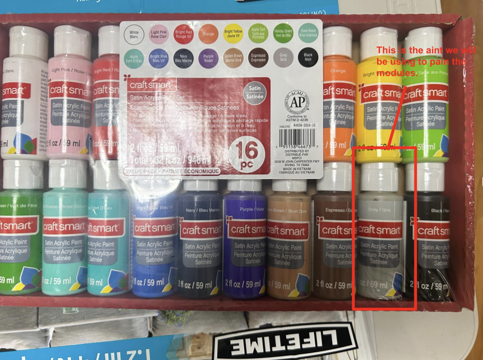
- CraftSmart paint
Tools;
- Pencil
- Inch tape/ a ruler
- A marker
- Some thing pointy to spread the super glue
- Gloves
- Scissors
Attaching the Windows
To give the abode a realistic appearance, incorporating proper windows in the assembly was essential. To achieve realistic looking windows, I used a material called Clear Acetate Sheets, a transparent material that accurately mimics the appearance of glass.
- The acetate sheets are available in 12 by 12 inch dimensions, and we will need to cut them into our desired sizes.
- The materials we will need to attach the windows are:
- Gloves
- Scissors
- Inch tape
- Gorilla glue
- Lock tight super glue
- Pointy part to spread the glue
- Clear Acetate sheets
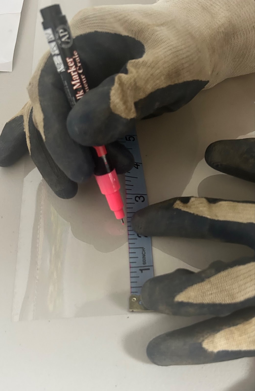
- After measuring all the areas designated for windows, use a marker to outline the windows on the Clear Acetate sheet using the dimension derived.
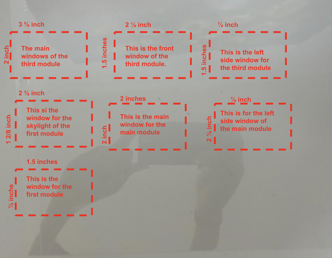
- Here are the exact dimensions of the different sized squares we need to cut out of the sheet for all of the modules.
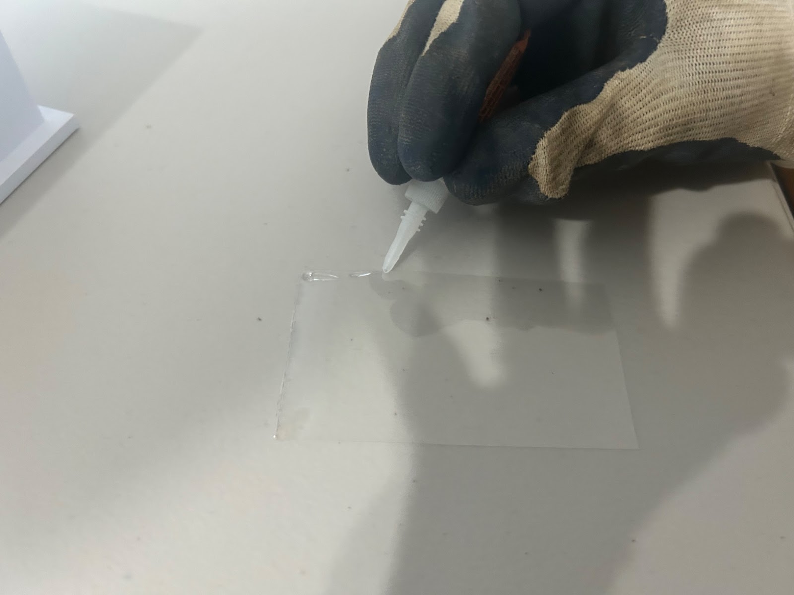
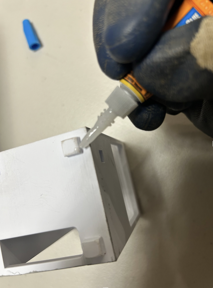
- After all the measuring is over we can start gluing on the windows from the insides. Be sure to wear the gloves when using the super glue, as contacts with skin can lead to serious irritation or injury.
- Attaching the main windows for the third module
- Attaching the two side windows of the third module:


Should look smth like this:

- Attaching the main window for the main module:
- Attaching the right side window for the main module:

- Attaching the small left window for the main module:

- Attaching the window of the first module:

- Attaching the skylight of the first module:

- The final look of all the modules with windows:

All the areas designated for windows should now be fitted with Acetate panes, significantly enhancing the realism of the model.
Add Colors to the Components
Adding collors to model will bring it to life and highlight its key features, such as the windows and structural details
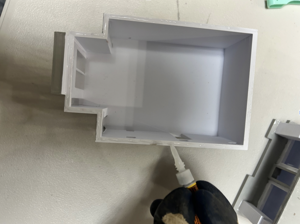
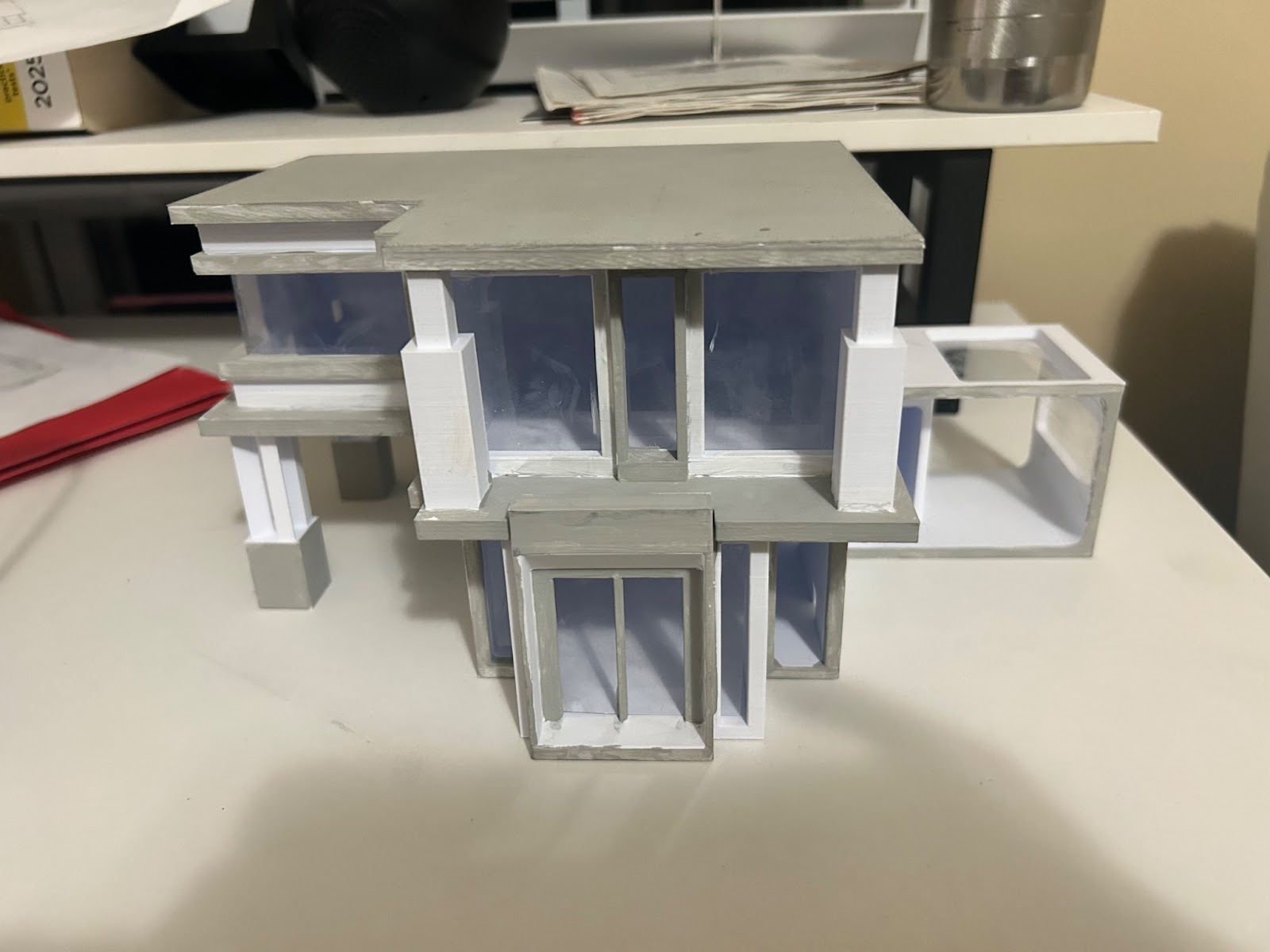
- We will use the color gray to highlight all the main strucutresd of the house, ths will addmsome dept and life to the models.
- The finished product:

Assembling All the Parts Together.
Finally, we can now move on to putting all the parts together.
- The materials we wil need:
- The 3d printed modular parts
- Gorilla glue
- Gluing and putting all the parts together.
- First, apply glue to teh top of the third modular unit.

- Attach the roof to the second floor now, and hold it in place till it dries.

- Next, apply glue to the top of the main module.
- Attach the third module with the roof onto the main module, make sure to hole it down.


- Apply glue to the conection points of the first module.
- Attach the first module to the assembly, by putting the conectoin points into the connections holes.
- Apply glue to the top part of the first pillar and the second pillar.

- Attach the two pillars to the whole assembly.

- Once all the parts are assembled, the finall structure should like this.
\
Capturing the Model in a Natural Setting
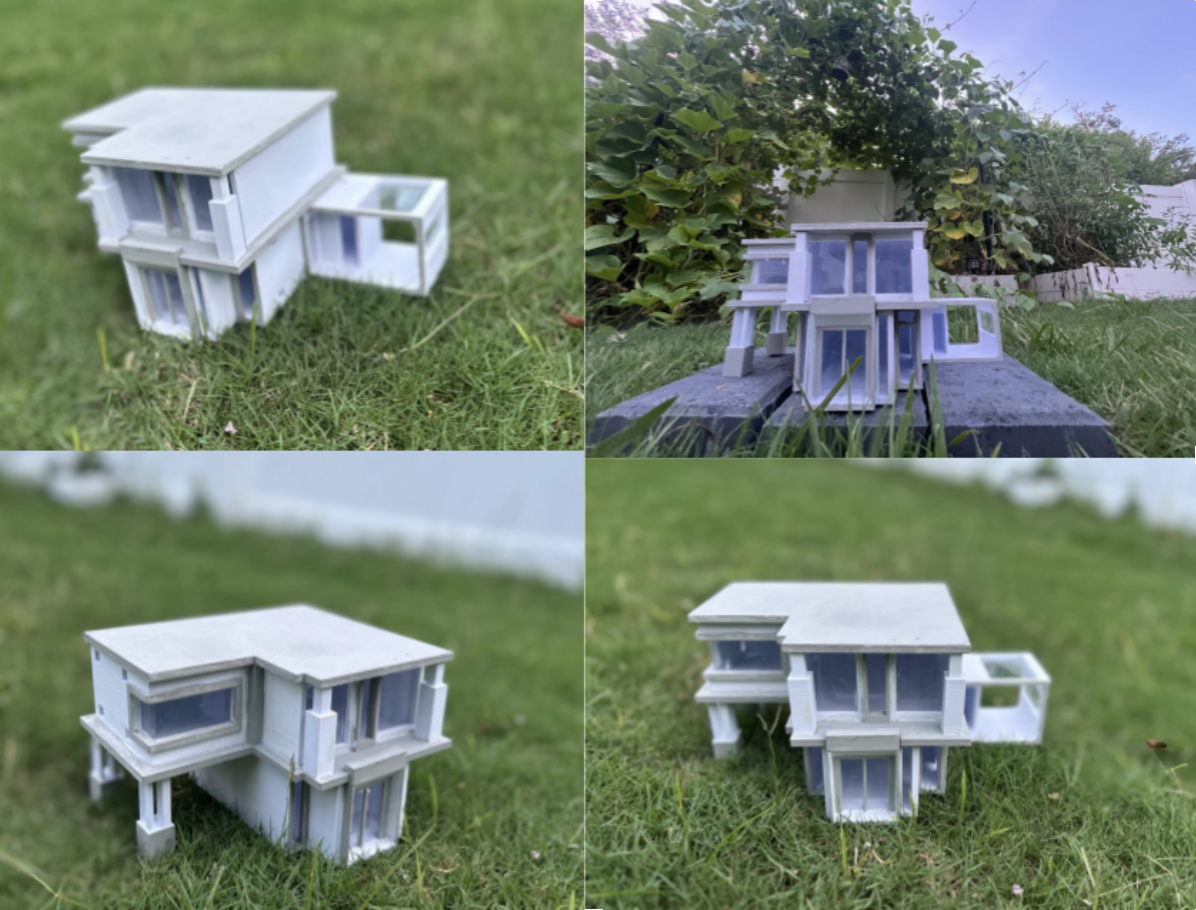
I wanted to get some good pictures of the house in the outdoors, which will not only provide a more realistic view but it also highlight how it blends into a natural setting.
Here are some of the pictures I got:
Acknowledgements:
While this project was quite a ride, I couldn't have done it without the help of my community.
First I would like to thank my parents for always being there. Whether it’s a late night trip to Michaels or a simple coffee to help me stay up, they always supported me through it all.
Next, my friends for always helping me. I really want to thank them for staying up on calls with me, or even just offering me some of their leftover PLA filament. They are the ones who made this project possible.
Last but not least, my Robotics team. The main reason I even finished this project is because my robotics team allowed me to take home the team's 3d printer in order to use it for myself, and for that I am extremely grateful. Especially with all the shenanigans that kept happening like when the print failed 2x before It finally worked. Thank you team 21829 Circuit Breakers for everything that you have given me!
Big thanks to the teams behind Fusion 360 and Instructables for offering students access to powerful design tools and a space to bring ideas to life. Taking part in this challenge pushed me to transform a rough concept into a wonderful creation, and the experience ended up being more rewarding and informative than I could have imagined.