Modular Backyard Solar Wedge Light
by technocraftStudio in Outside > Backyard
8819 Views, 59 Favorites, 0 Comments
Modular Backyard Solar Wedge Light
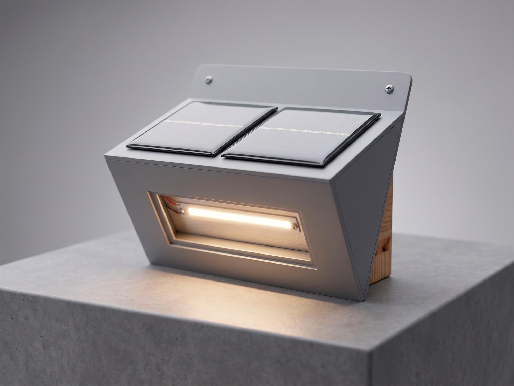
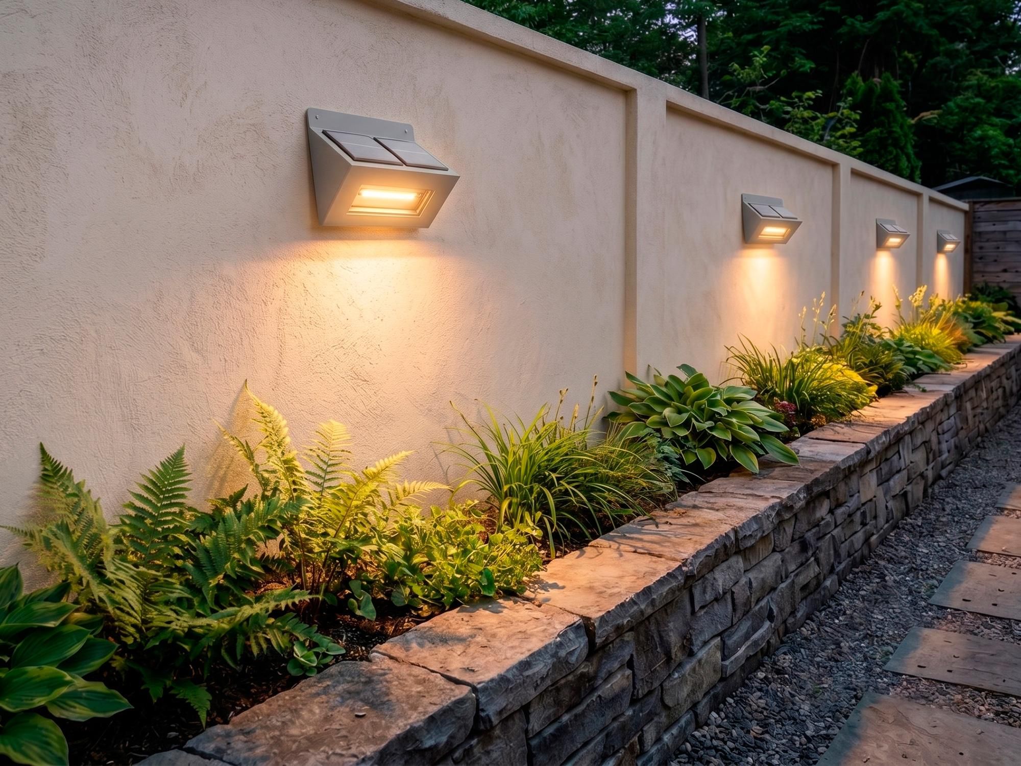
Outdoor lighting can transform a backyard garden, pathway, or boundary wall, but commercial solar lights often lack durability, brightness, and custom repairability.
This project demonstrates how to build a compact, weatherproof Solar Wedge Wall Light completely from scratch using upcycled PVC pipe. Designed as a clean wedge unit, it features top-mounted solar panels to maximize daytime energy harvesting and a downward-facing COB LED window that casts a warm, glare-free accent beam along fences, garden beds, or house walls.
- Key Features & Innovation:
- Upcycled PVC Construction: Made by heat-flattening low-cost PVC pipe into a rigid, 100% waterproof housing that withstands outdoor elements better than cheap plastic.
- Hidden Touch Control: Utilizes a concealed TTP223 Capacitive Touch Sensor mounted inside the sealed PVC wall—allowing you to toggle power simply by tapping the outside of the casing without drilling holes for mechanical switches.
- Efficient COB LED Engine: Powered by a high-brightness 4V COB LED strip mounted on a custom aluminum heatsink plate with thermal compound to maintain low operational temperatures and long LED life.
- Modular & Serviceable Design: Internal components are mounted using wooden anchor blocks, JST quick-connect plugs, and removable rear panels—making battery replacement or circuit maintenance simple in the future.
- Why Build This?
- Whether you need accent lighting for a backyard fence, path guidance along a dark wall, or simply want to create a polished off-grid solar project from repurposed materials, this build combines clean craftsmanship with practical circuit design!
Future Upgradibility:
- Automatic Dusk-to-Dawn Operation: Integrated solar charge controller and auto-switch circuit harvest sunlight during the day into an internal 18650 Li-ion cell and automatically illuminate the light at nightfall.
Supplies
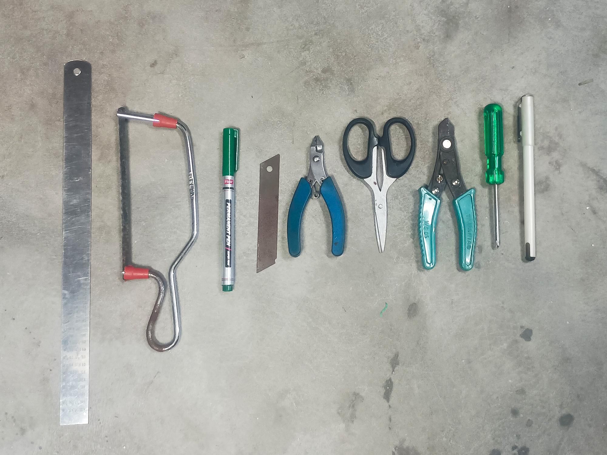
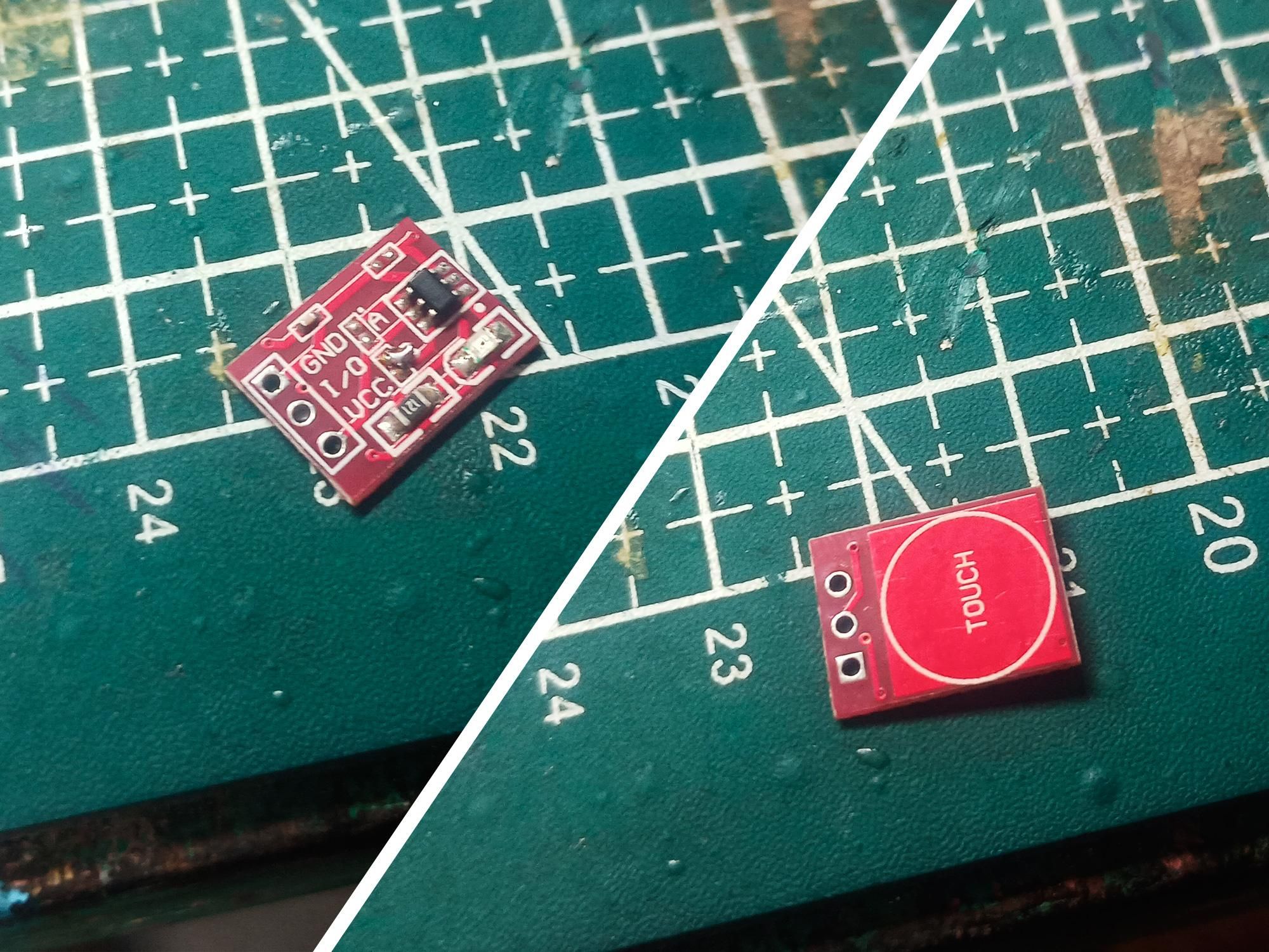
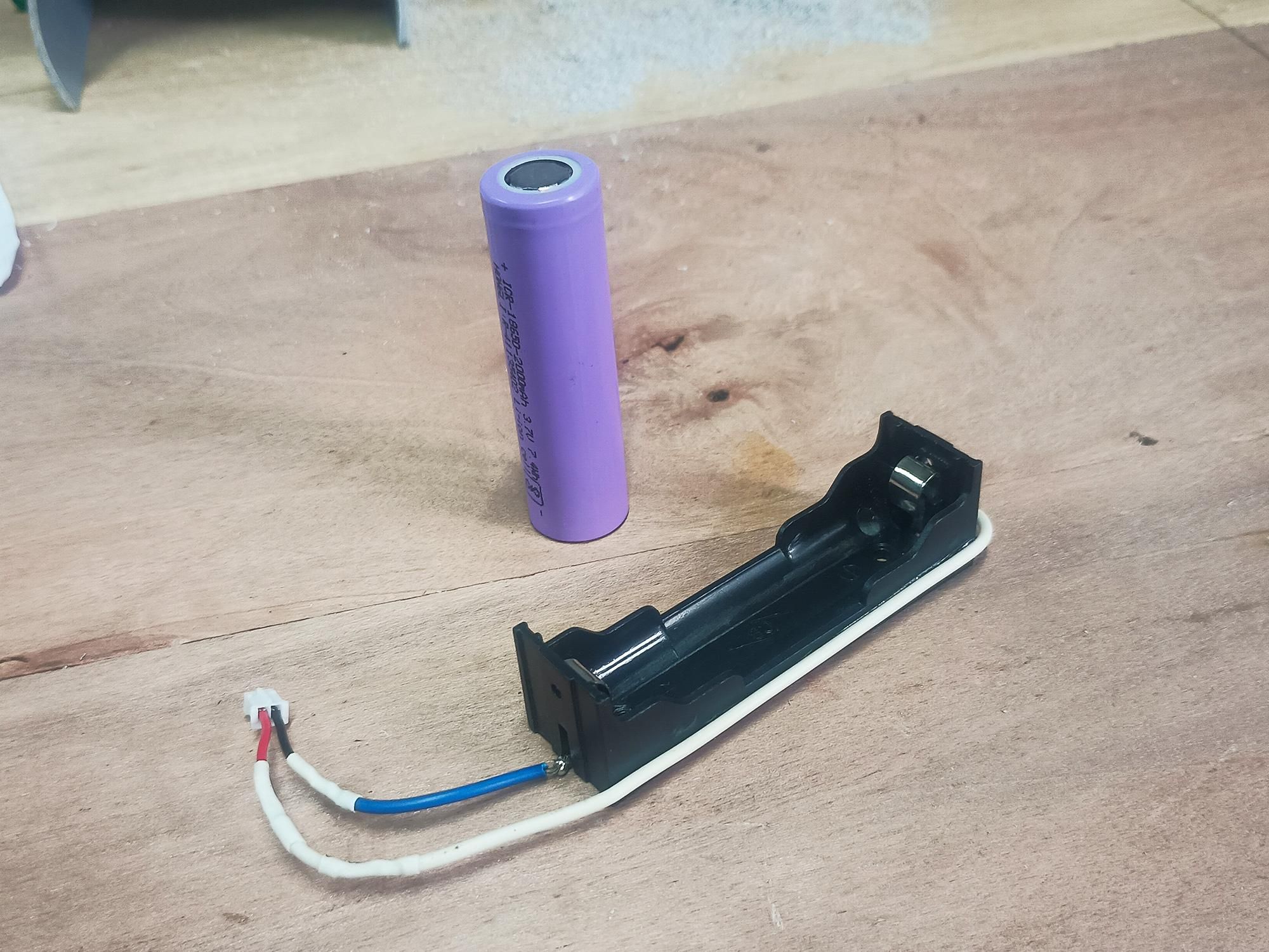
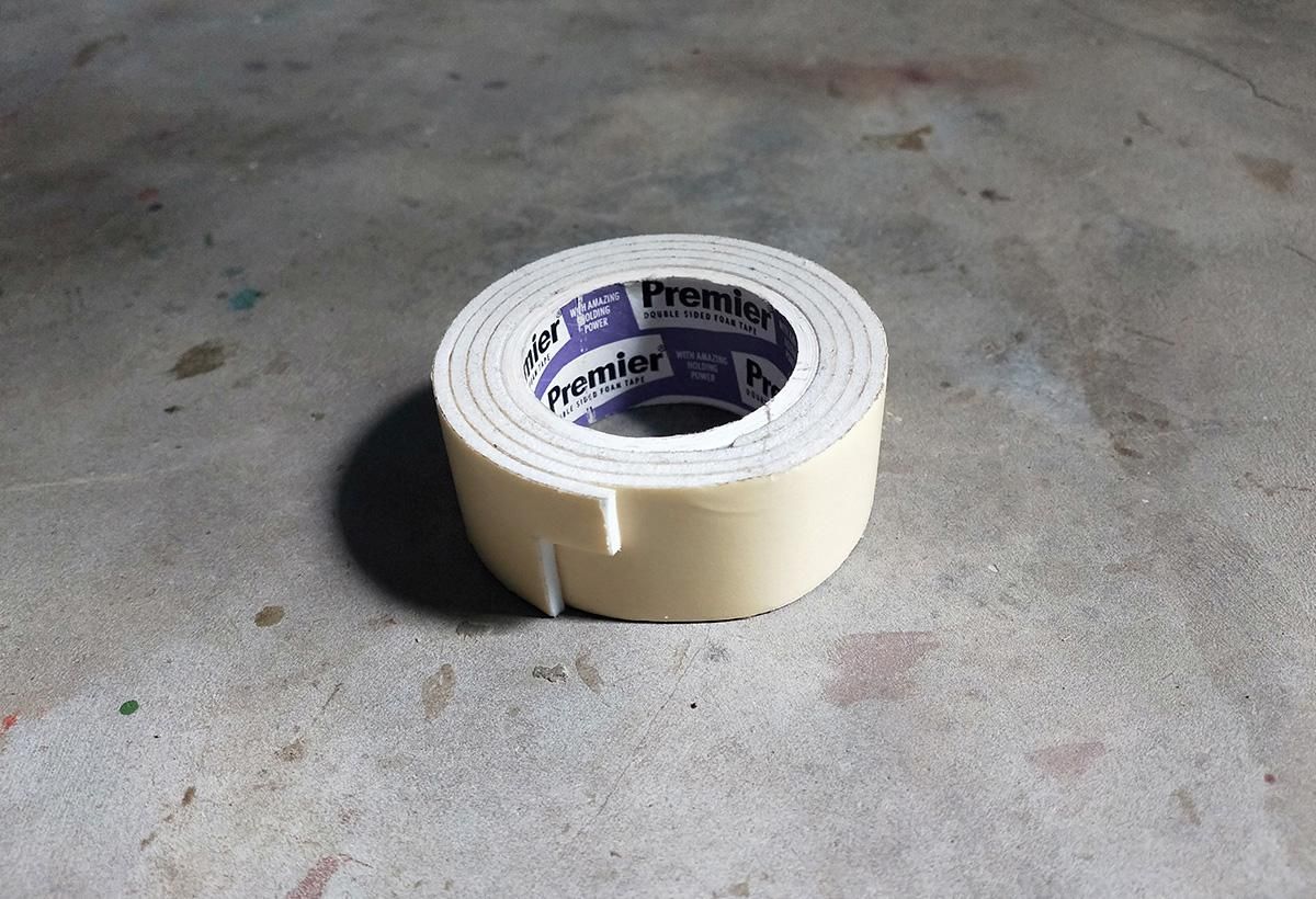
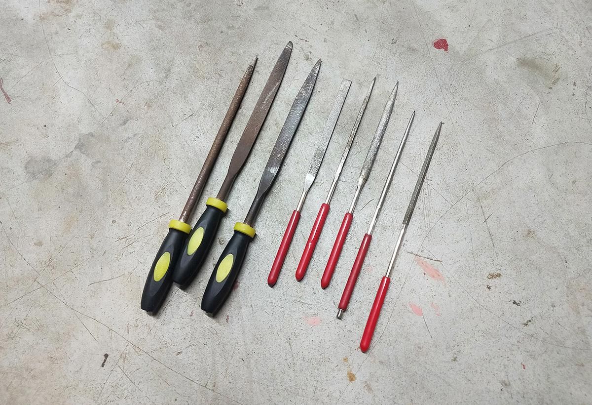
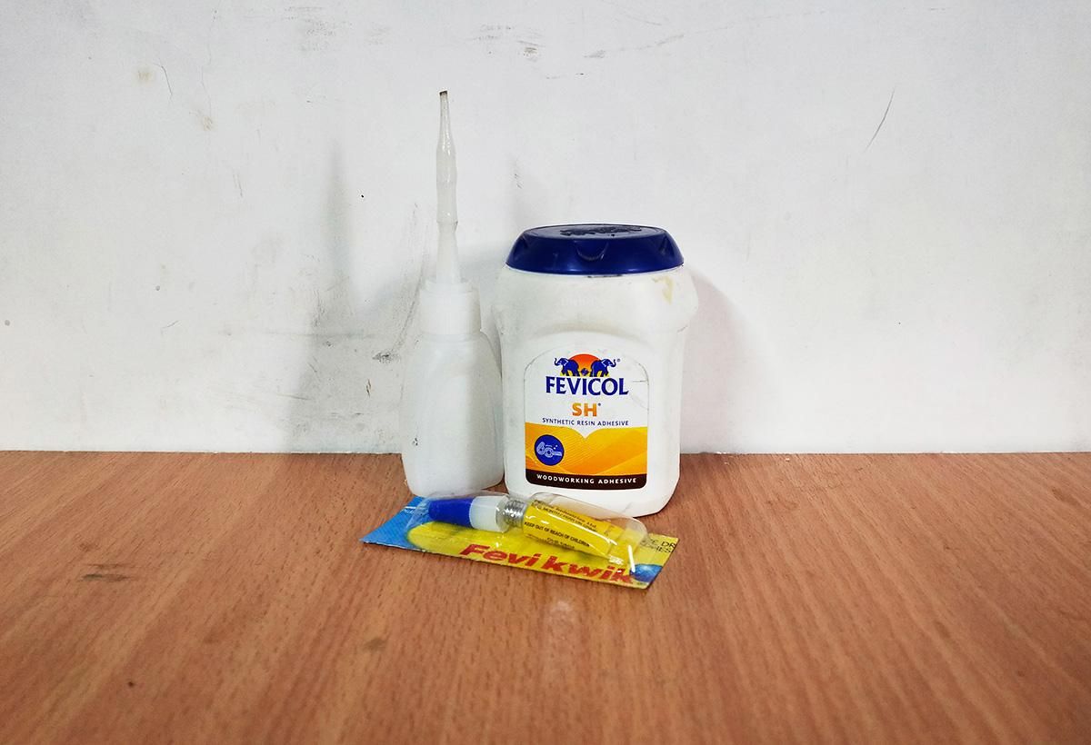
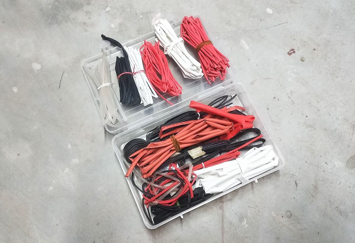
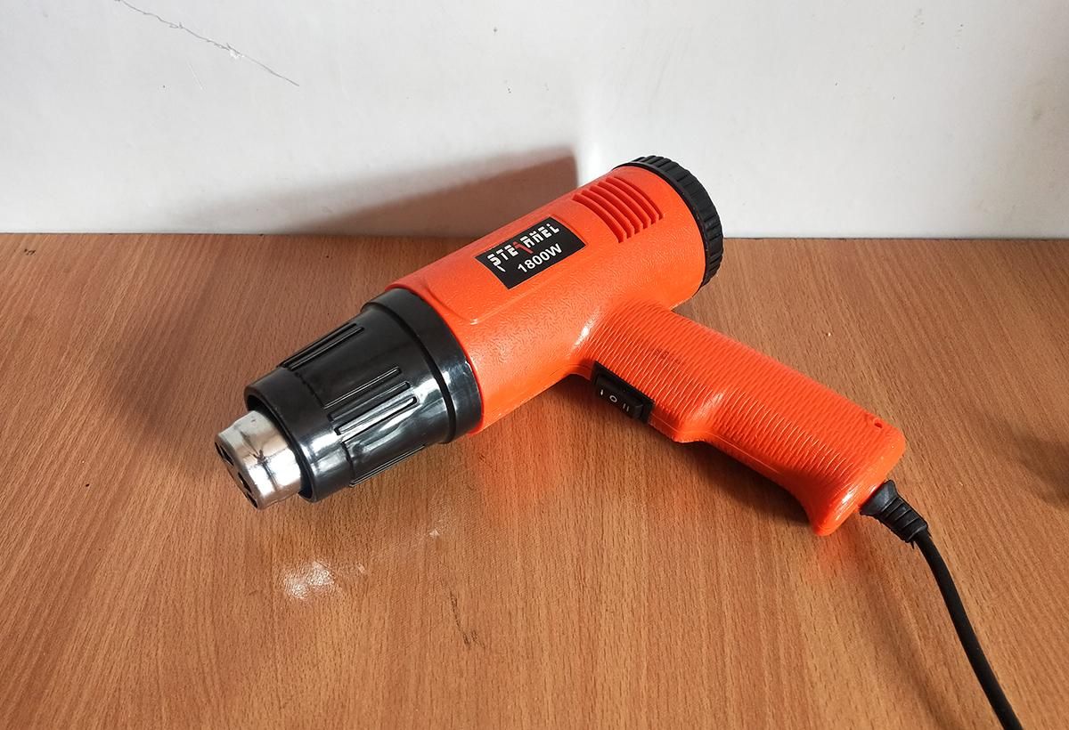
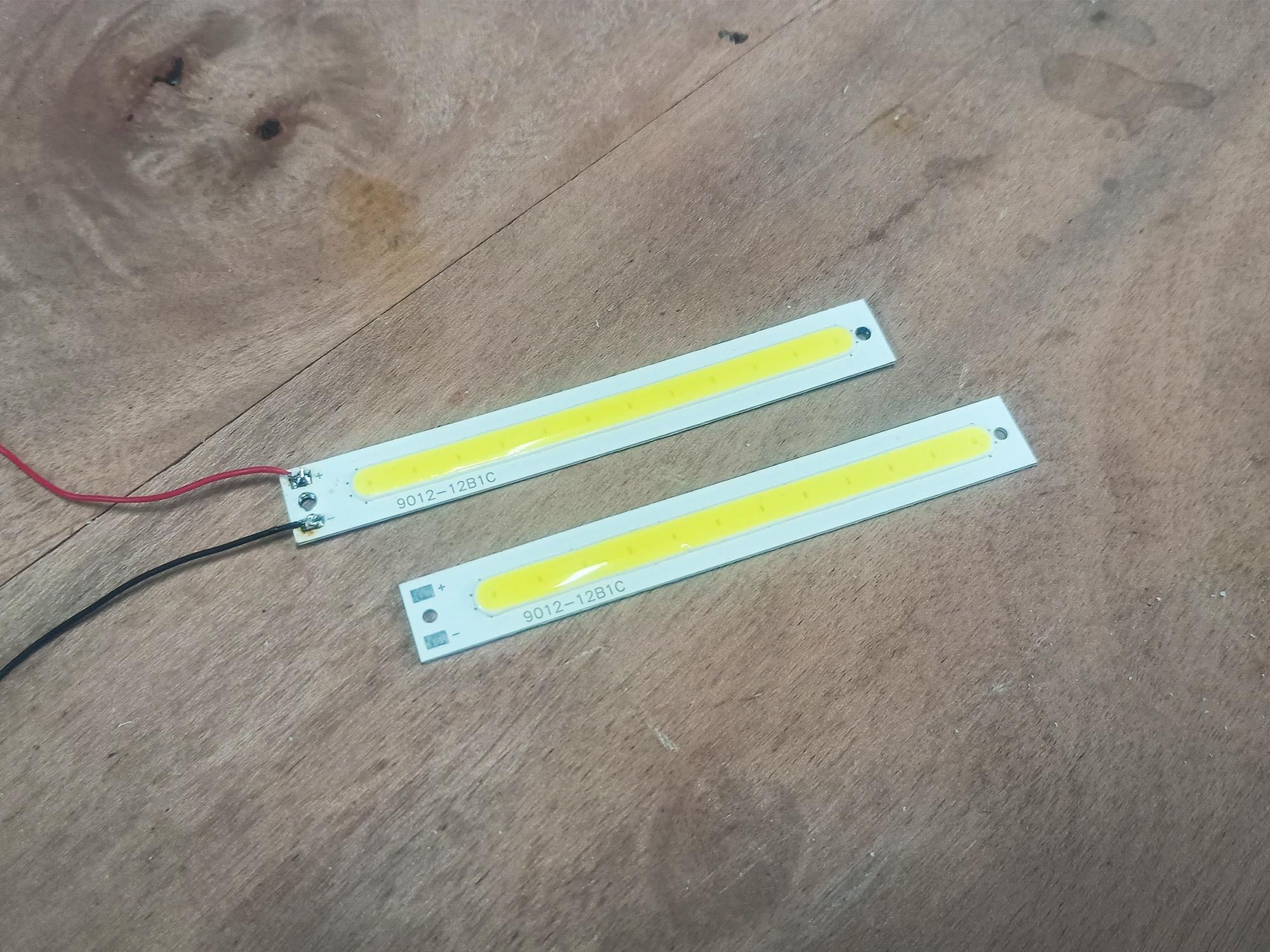
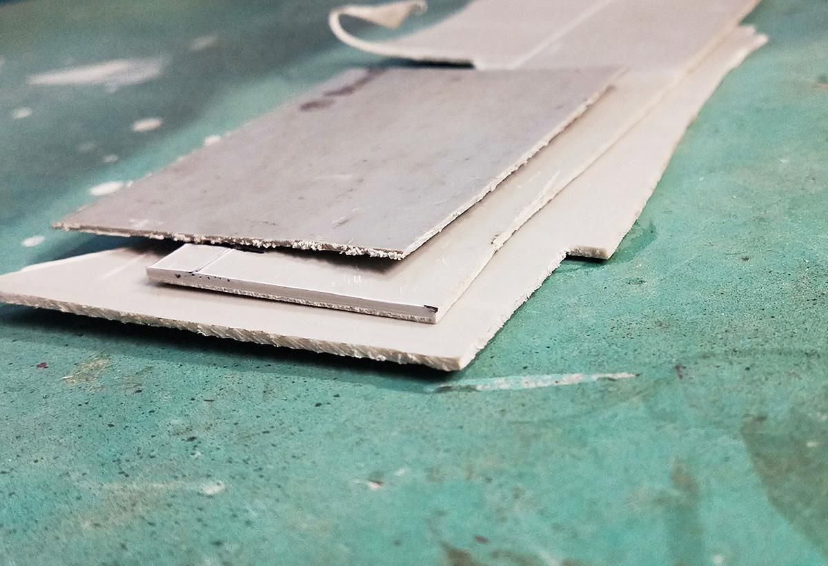
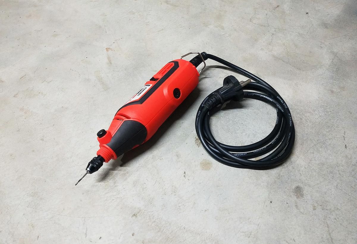
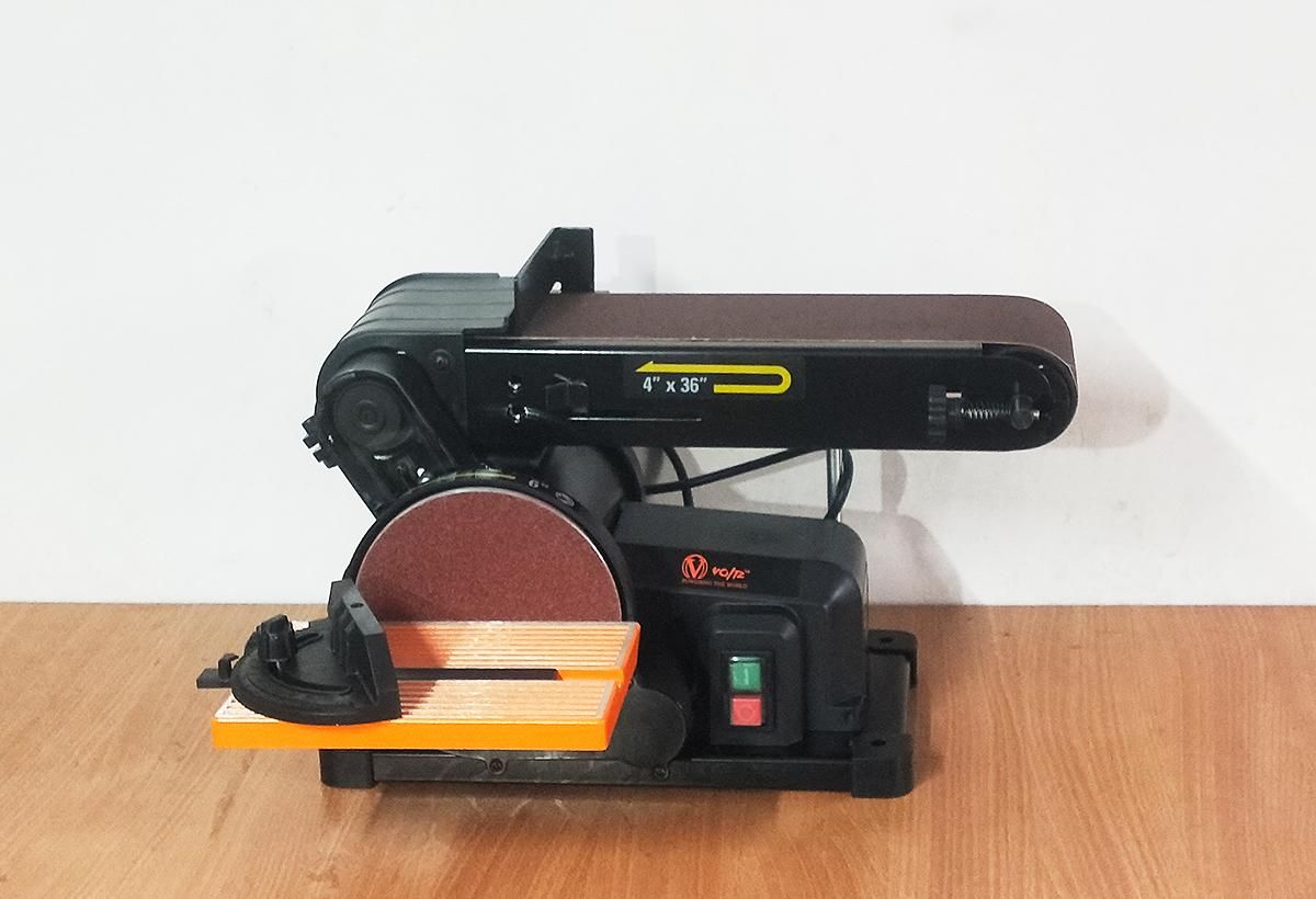
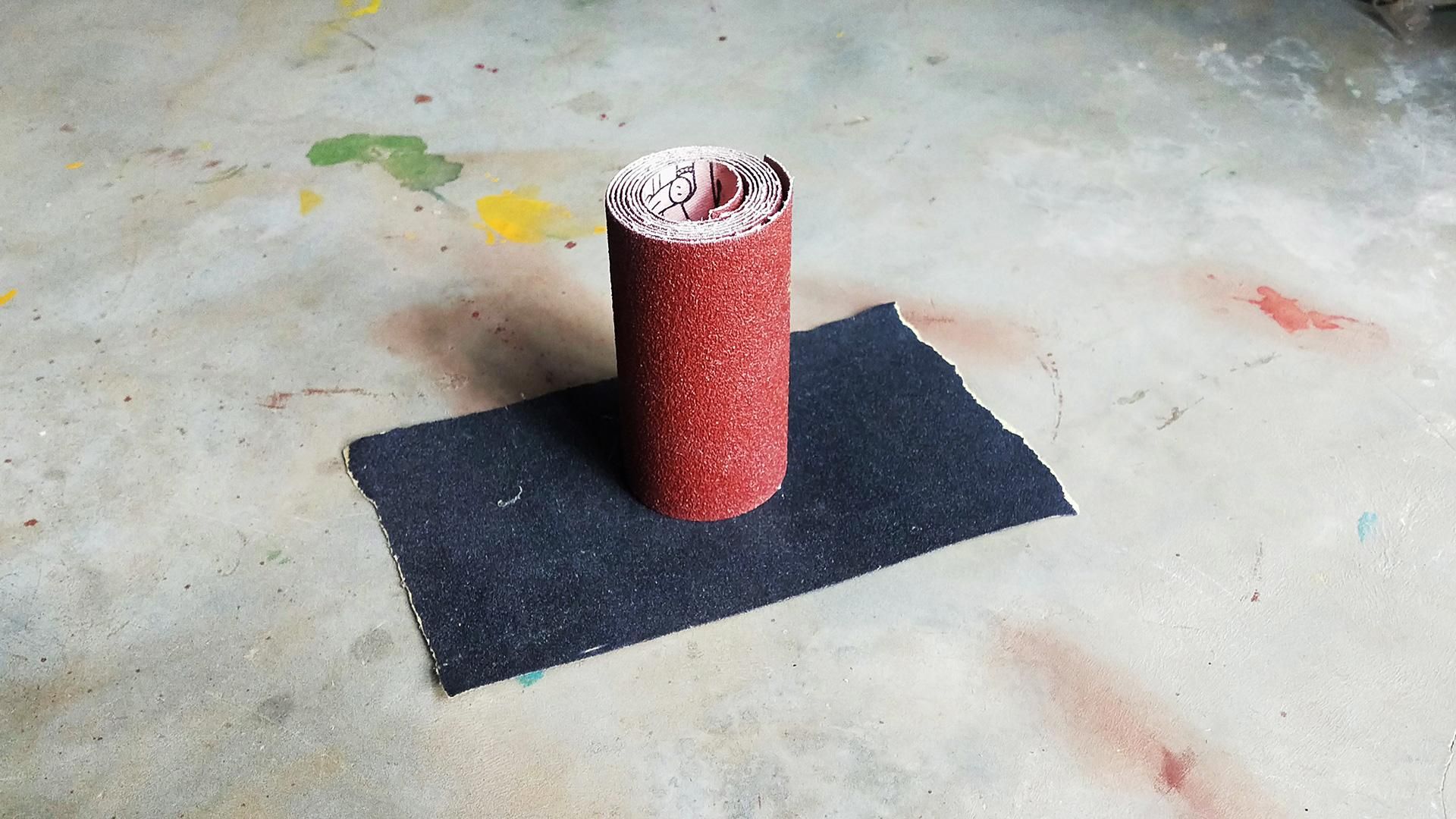
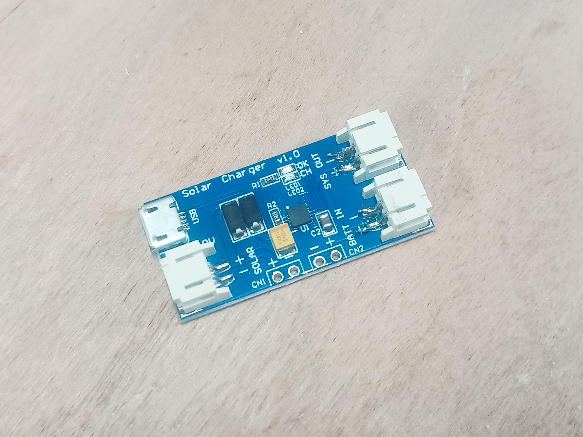
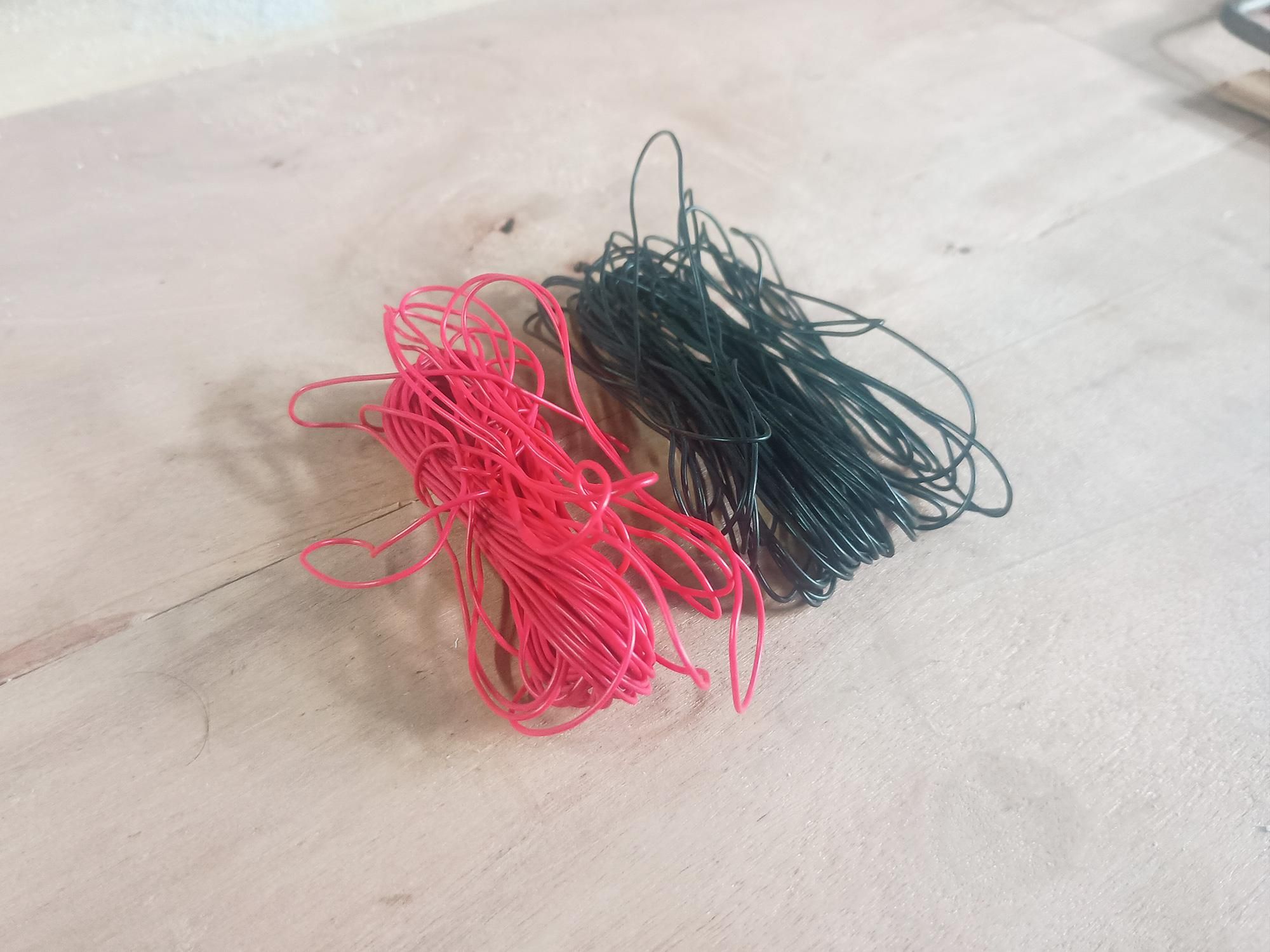
Everything you need for this build is inexpensive, easy to find, and can be customized to fit components you already have on hand.
Gather the following electronics, hardware, and raw materials before starting your assembly.
Materials:
- PVC Pipe Sheet: Flat sheet (cut/flattened from a PVC pipe)
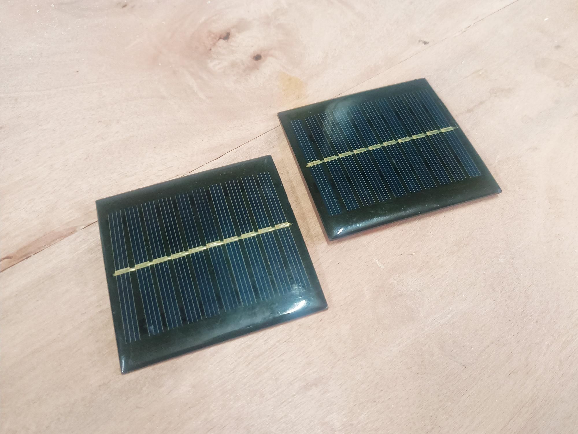
- Solar Panels: 2 pcs (6V, 100mA)
- Battery: 3.7V, 1200mAh Li-ion battery (18650)
- LED Light: 4V COB LED panel
- Charging Module: MPPT Solar lithium battery charge controller
- TP223 Touch Module: Sensitive touch switch module
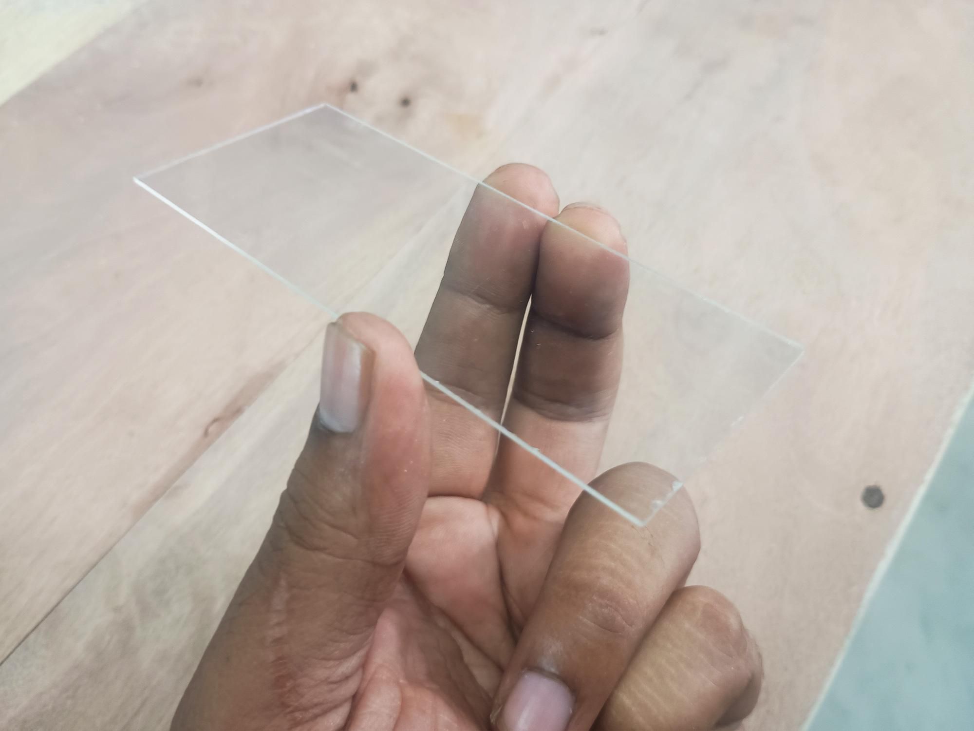
- Diffuser: Clear or frosted acrylic sheet (1-2mm thickness)
- Adhesive & Hardware: Clear outdoor silicone, PVC sealant, superglue, connecting wires, and mounting screws
- Wires: Red & Black Wires
- Heat Shrink Tube: 1mm, 2mm red & black or white tubes.
- Scrap Wood pieces.
Tools
- Heat gun (or heat source for flattening/bending PVC)
- Hot glue gun
- Utility knife or fine-tooth handsaw
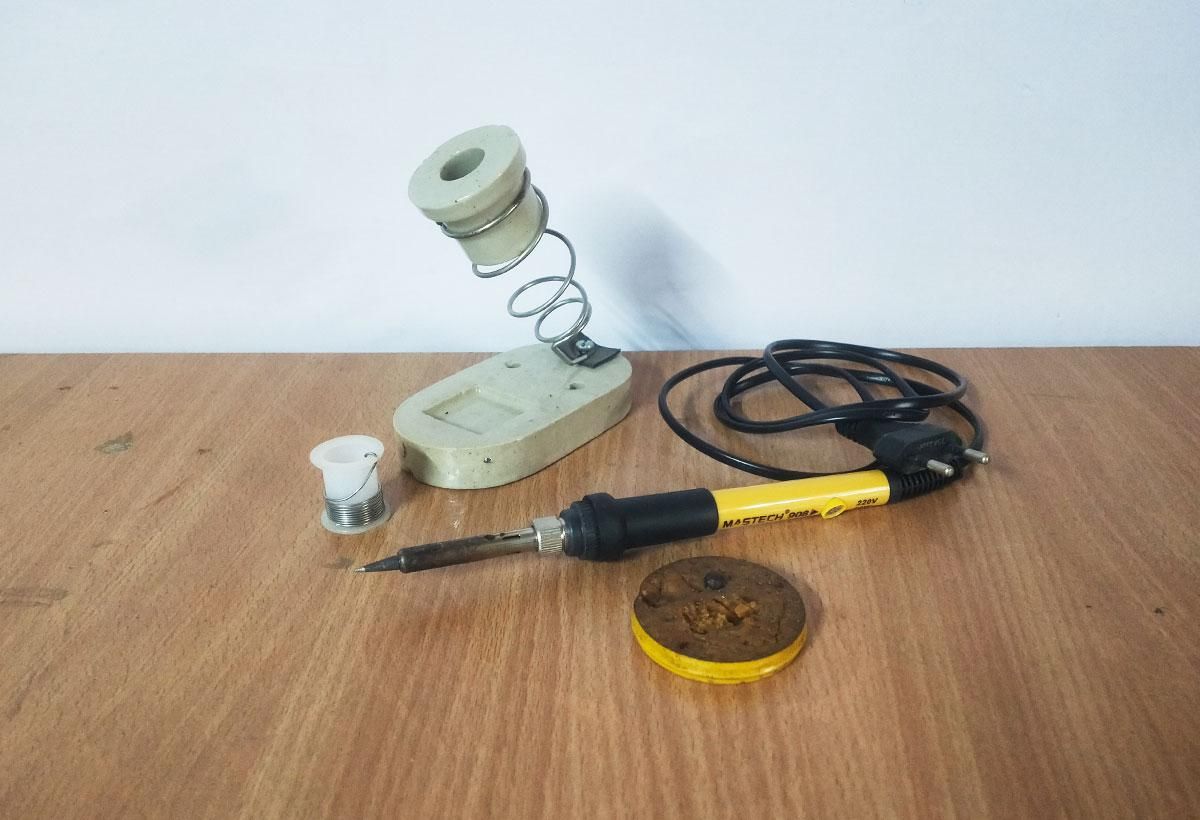
- Soldering iron & solder
- Drill with small bits (3-5mm)
- Sandpaper (120 and 240 grit) & Files
- Plier or Nipper
- Double Sided Tape
- Screws
- Ruler, Marker, Screwdriver
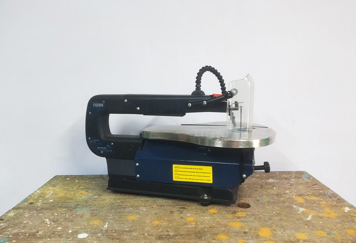
- Hacksaw or Scroll saw
Design, Planning & Measurements


Before cutting into materials, laying out dimensions and planning component placement ensures a compact, weatherproof design. The objective is to build a sleek wedge enclosure that maximizes solar panel exposure on top, casts light downwards, and keeps all sensitive electronics hidden and protected inside.
1. Dimension Breakdown :
- Top Solar Deck: 165m x 90mm
- Accommodates two 70mm x 70mm solar panels placed side-by-side with a 10mm border and 5mm spacing between panels.
- Roof Tilt Angle: 15 degree forward slope
- Prevents rainwater and debris from pooling on top of the panels while ensuring optimal sunlight exposure.
- Bottom Light Window: 165mm x 90mm
- Pointed directly downwards to cast a wide beam along fence posts, walls, or garden pathways.
2. Panel & Wiring Layout :
- Parallel Solar Panel Wiring:
- Wires from all three 6V, 100mA panels run into a central channel directly under the top deck.
- Wiring them in parallel (+ to +, - to -) yields 6V, 200mA max output, ideal for the charging controller.
3. Cutting Template Guide :
Prepare your flat PVC sheet and mark the following key panels using a ruler and fine marker:
- 1x Top Roof Plate: 165mm x 90mm (drill three 2mm wire routing holes inside the panel footprints)
- 1x Rear Mounting Backplate: 165mm x 145mm
- 2x Triangle Side Walls: Base 90mm, Side 90mm, Top 130mm
- 1x Lower Light Deck Partition: 165mm x 90mm
- 1x Bottom Acrylic Lens Cover: 110mm x 45mm, (1-2mm clear or frosted acrylic)
Pro Tip: Keep offcuts! Small PVC scraps can be used to make interior mounting brackets for the circuit module and battery holder.
Preparing & Flattening the PVC Sheeting
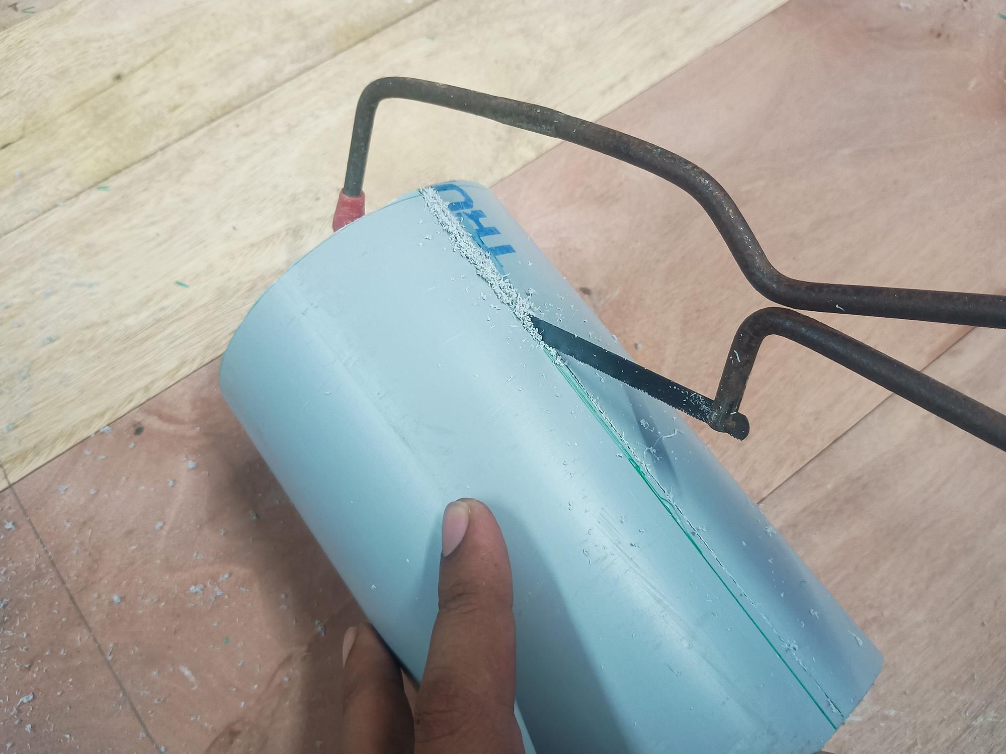
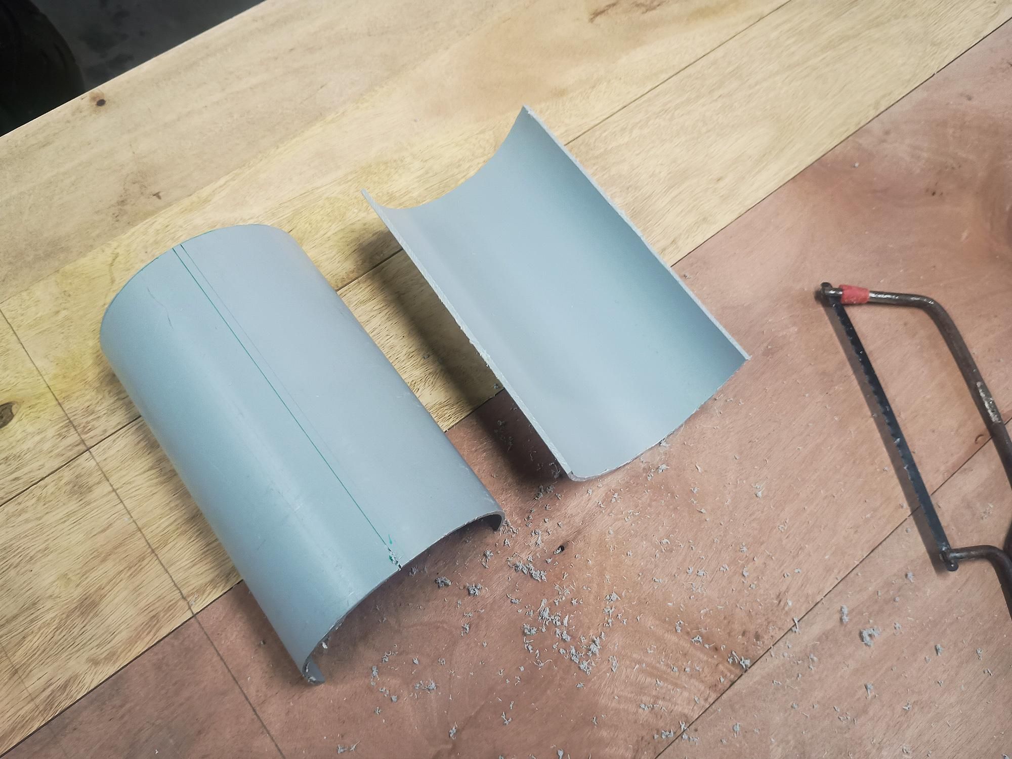
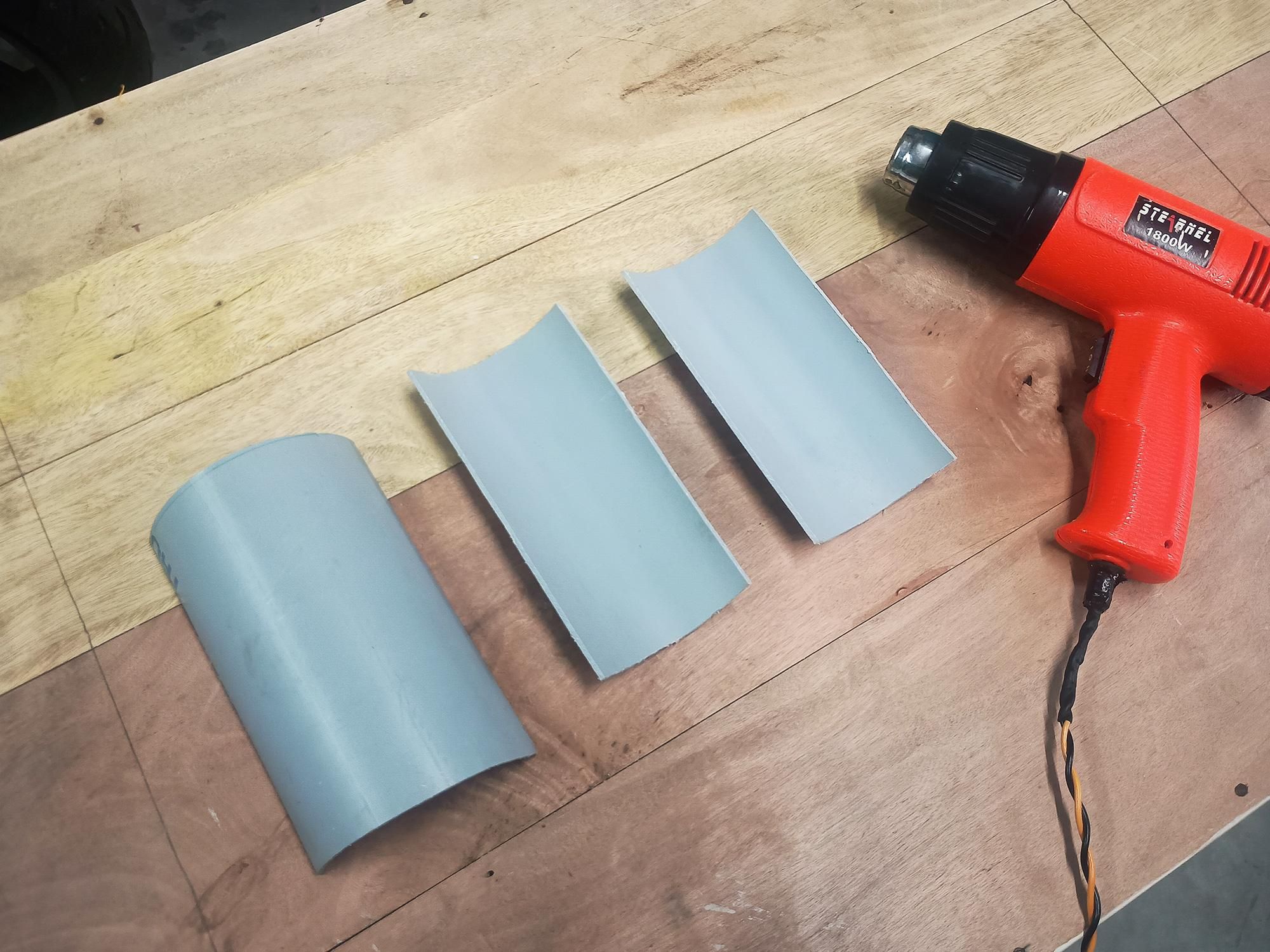
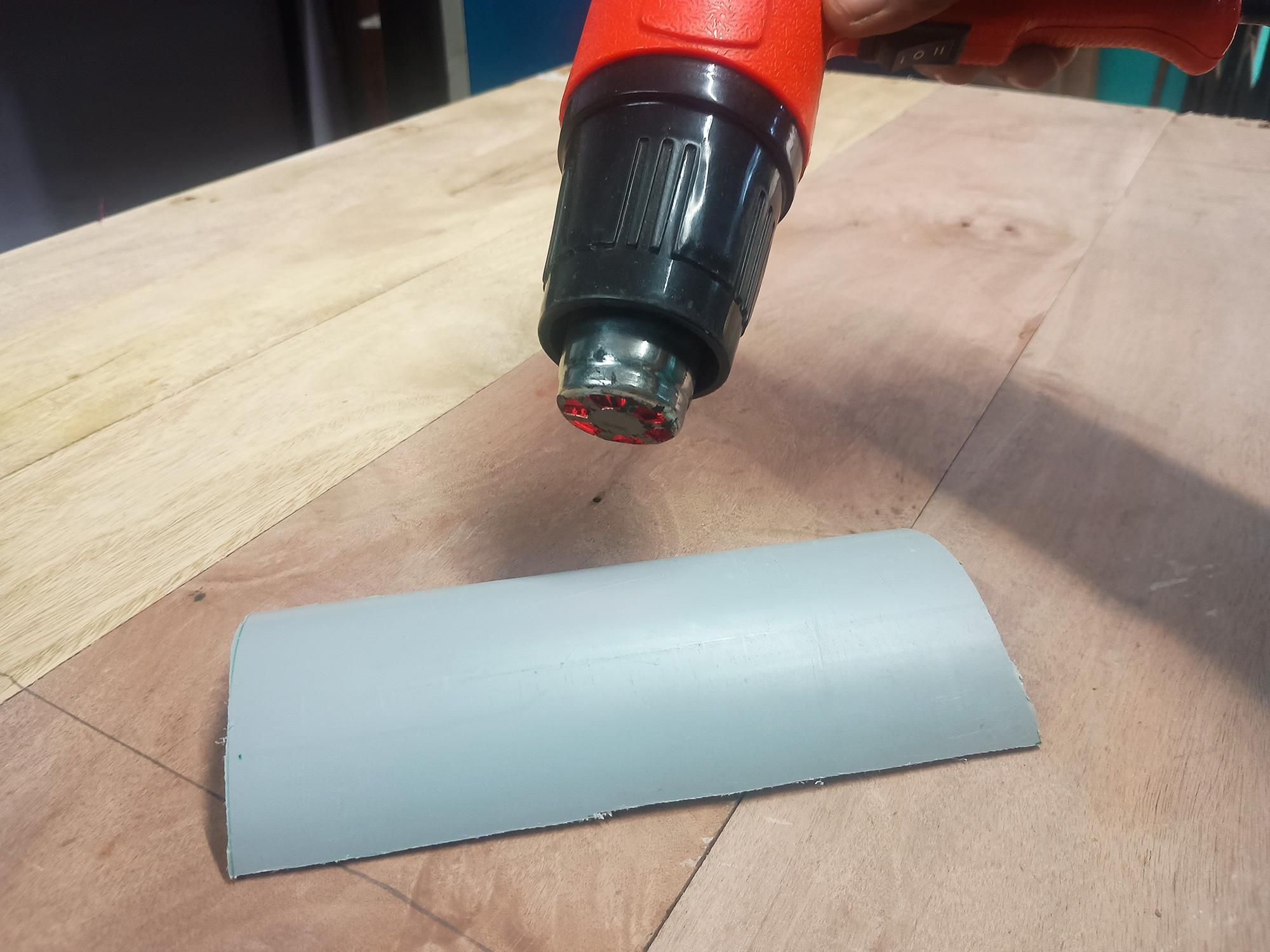
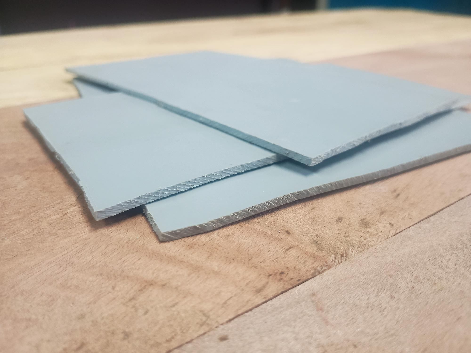
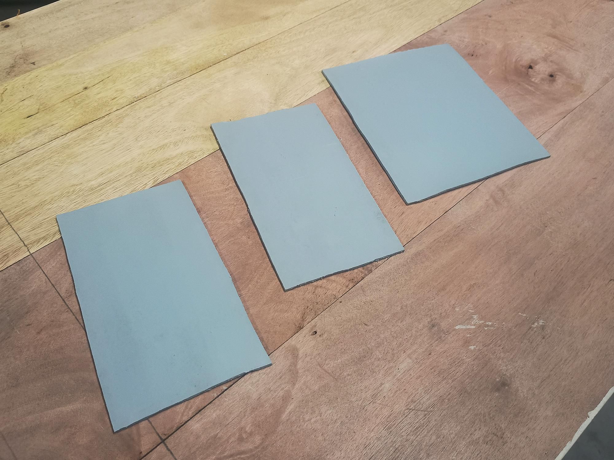
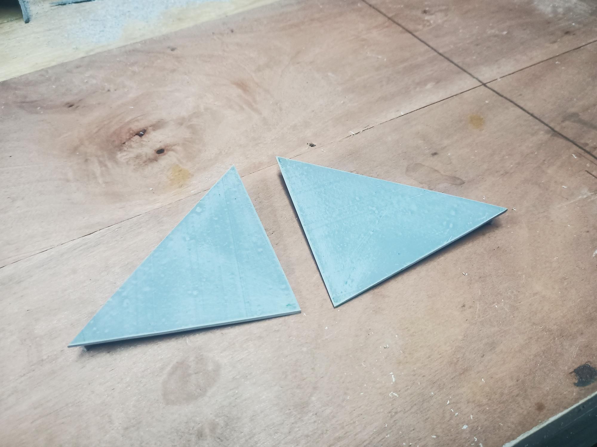
Using flattened PVC pipe is an eco-friendly, cost-effective way to create custom enclosures. PVC sheet is waterproof, tough, easy to drill, and takes paint extremely well.
- Mark and cut the following pieces from your PVC sheet :
- Top Roof Plate (1x): 165×90 mm
- Drill two 2 mm holes inside the panel footprint to route solar wires inside.
- Back Mounting Plate (1x): 165×145 mm
- Side Walls (2x): 130 mm high, 90 mm base and width.
- Flattening Process (Heat Gun Method) :
- Place a smooth wooden board or marble tile on a sturdy, heat-safe surface. Have a second flat board and heavy weights (or C-clamps) ready nearby.
- Set your heat gun to medium/high.
- Keep the gun 10-15cm away from the pipe and move it continuously in sweeping motions back and forth along both the inside and outside surfaces.
- After 3-5 minutes of uniform heating, the pipe will become flexible and soft like rubber.
- Unroll the softened pipe onto your baseboard, cover it immediately with the second flat board, and press down firmly.
- Apply heavy weights or place C-clamps on the board corners.
- Let it cool undisturbed for 1 minute until the plastic hardens into a perfectly flat, rigid sheet.
- Surface Surface Prep & Sanding :
- Once cooled, sand both sides of the sheet using 120-grit sandpaper.
- Why? This removes gloss, cleans off heat marks, and creates a microscopic texture that helps PVC cement and paint adhere securely.
- Give it a light pass with 240-grit sandpaper for a smooth surface finish.
Cutting & Shaping the Bottom Panel
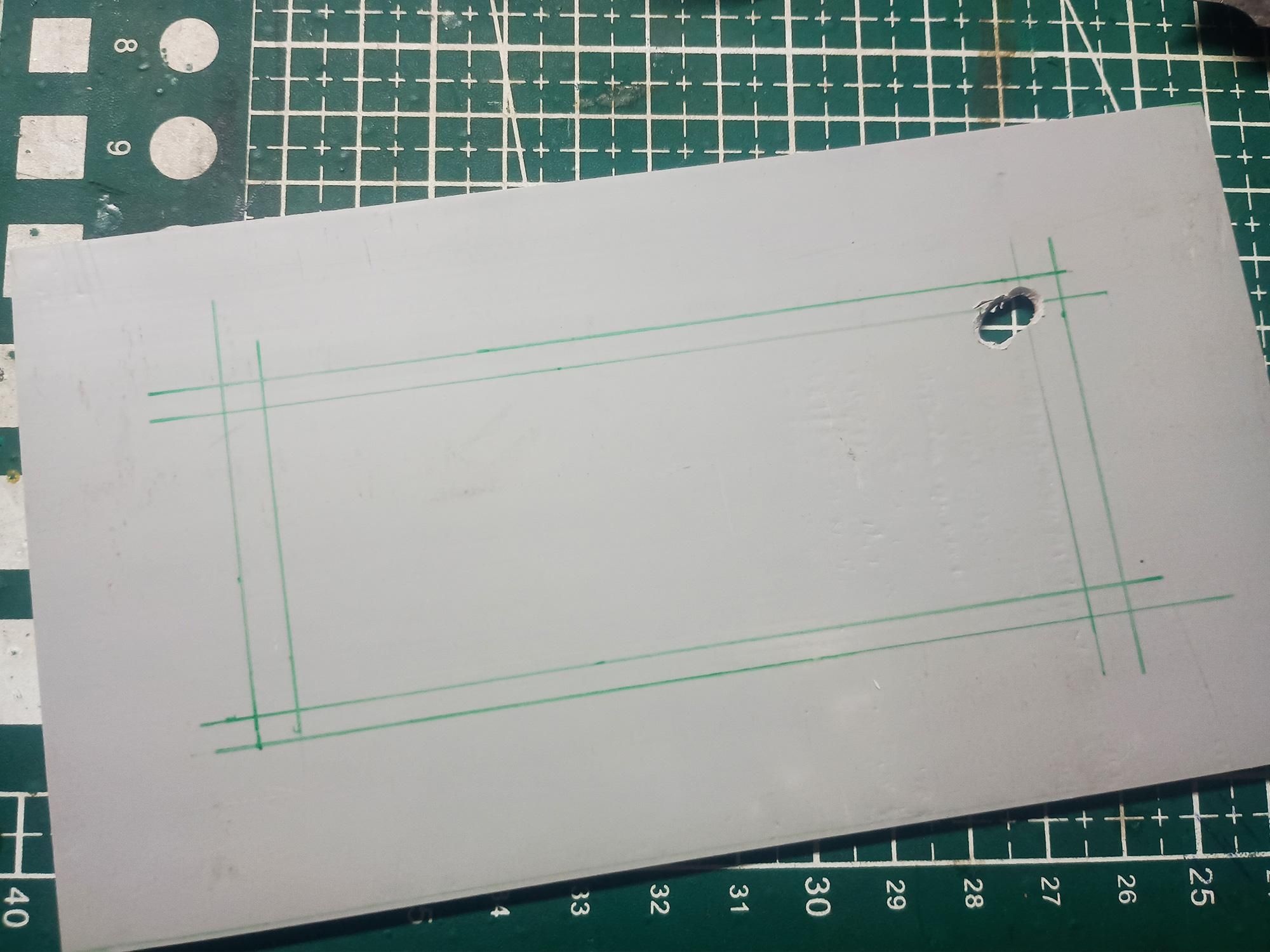
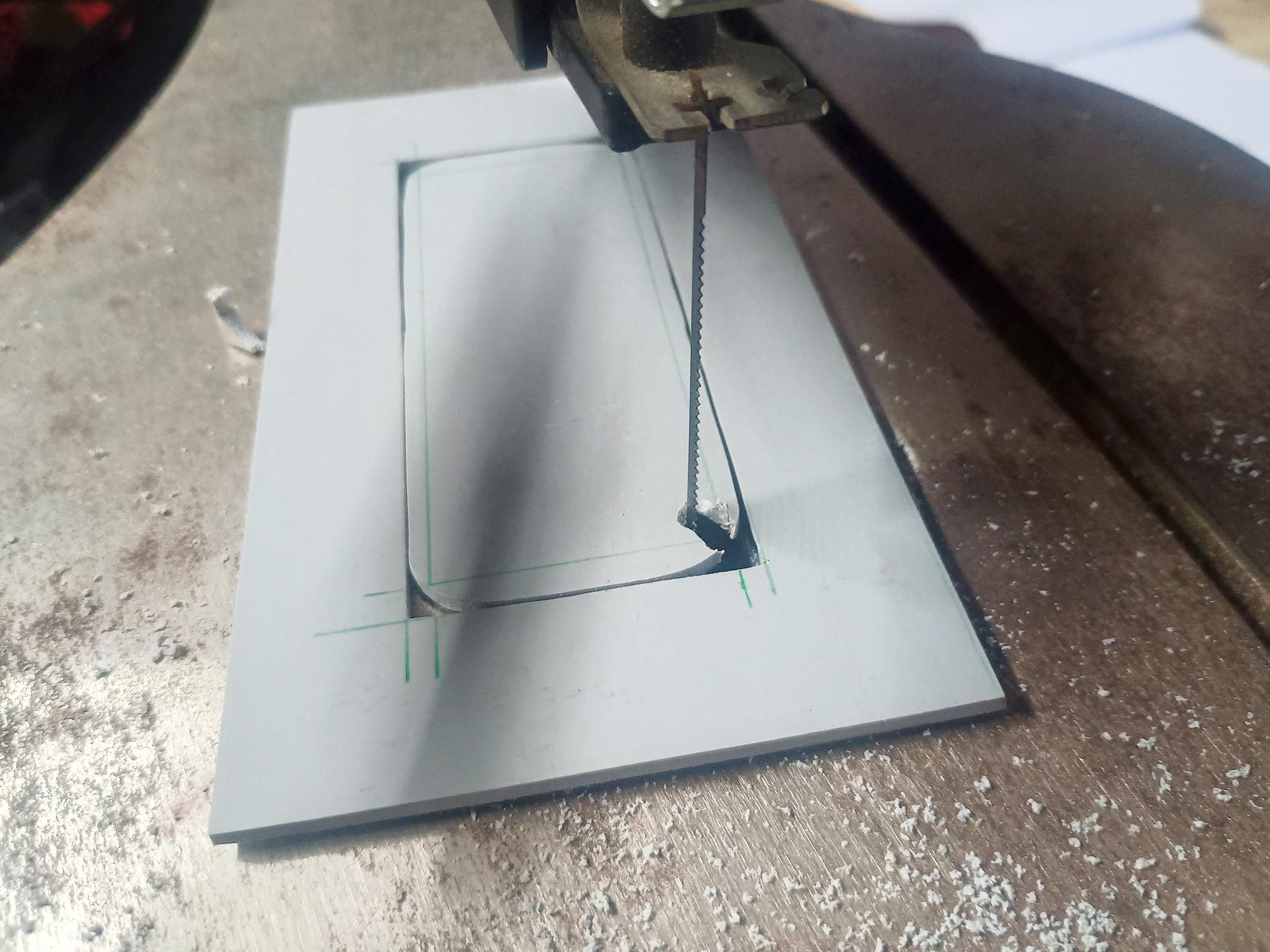
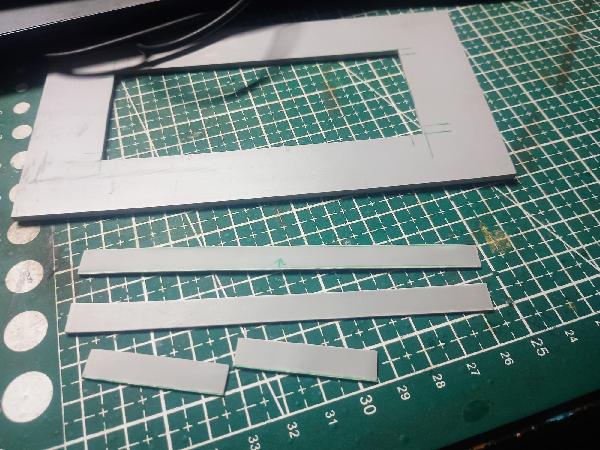
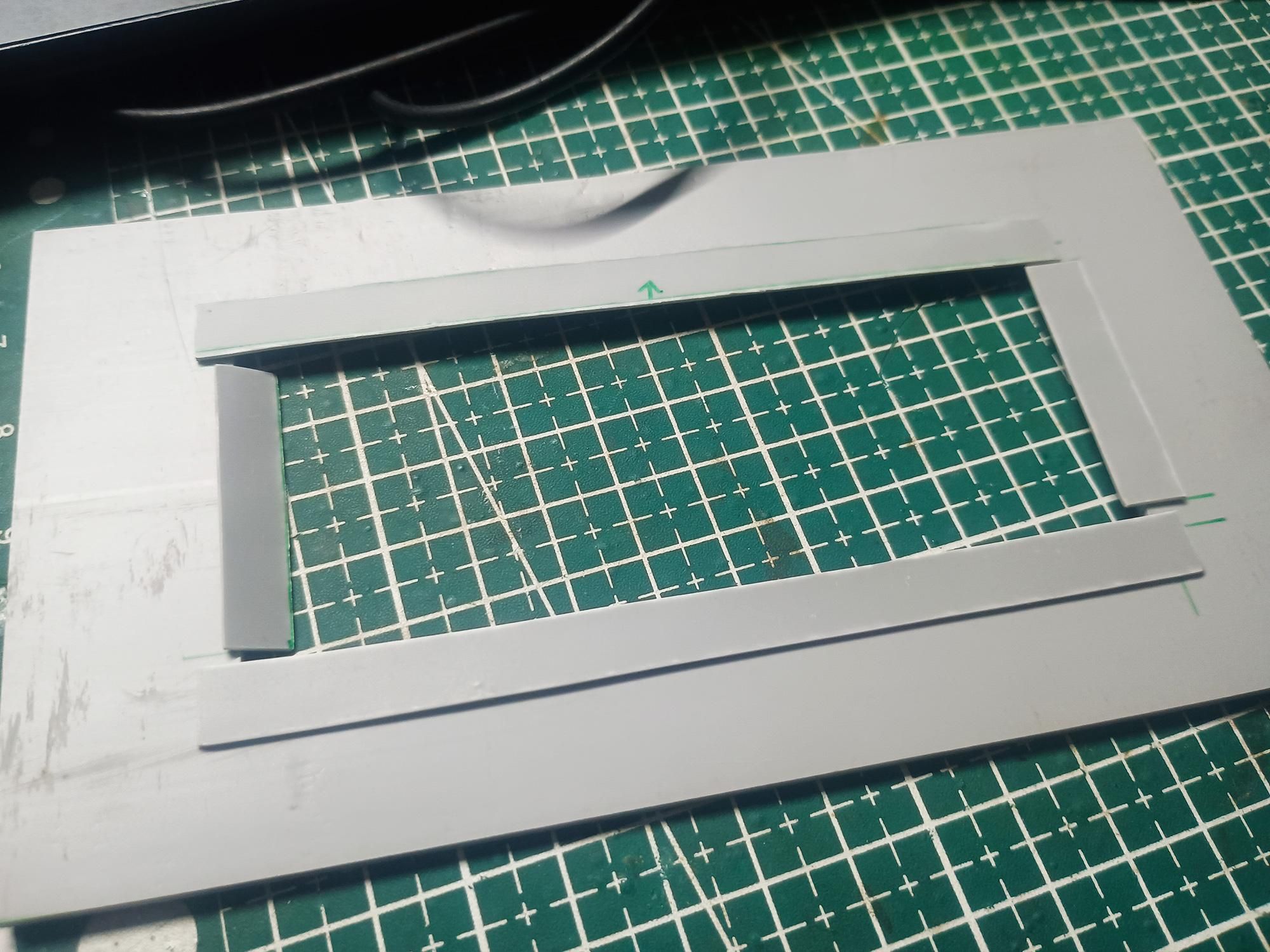
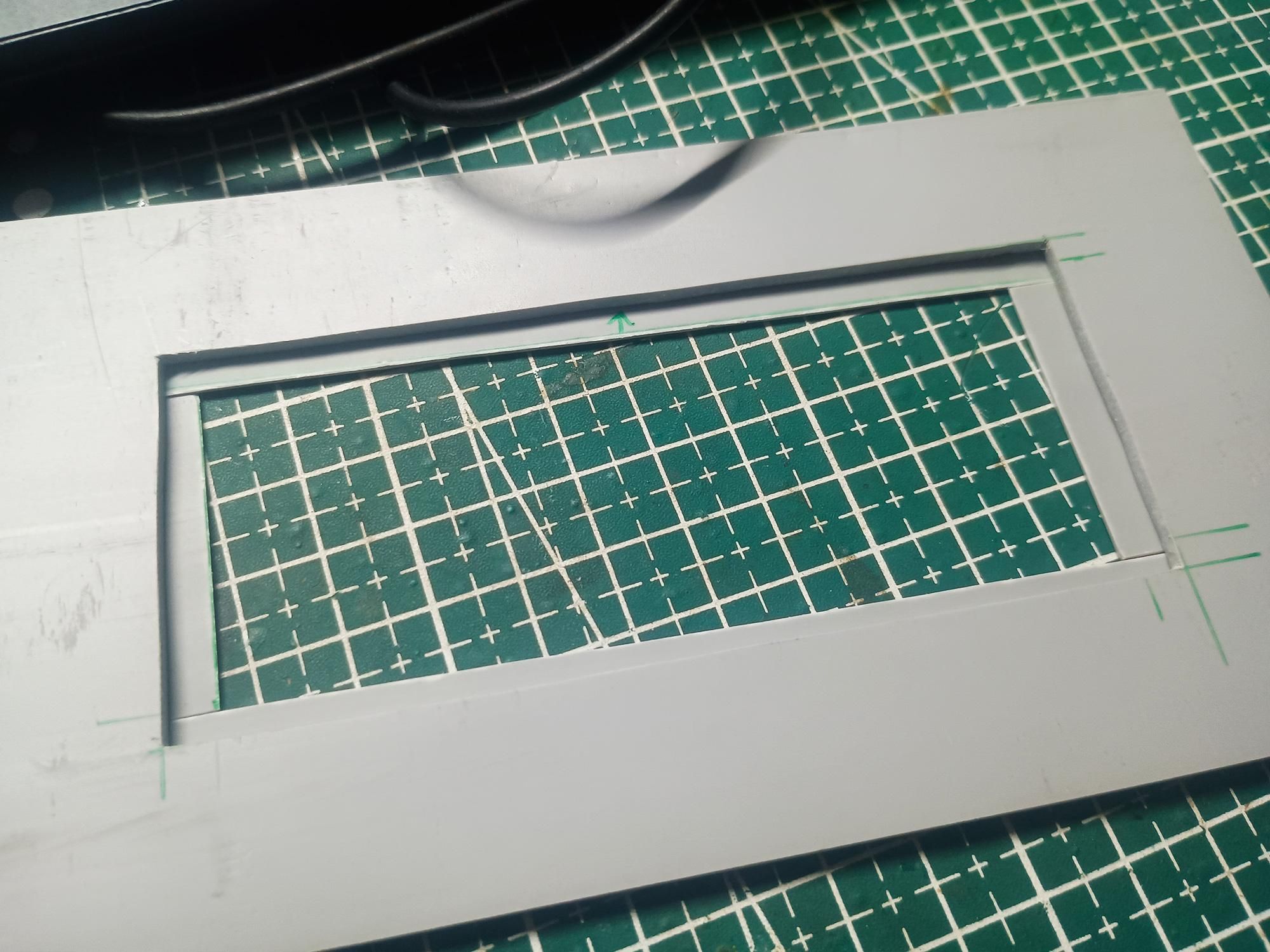
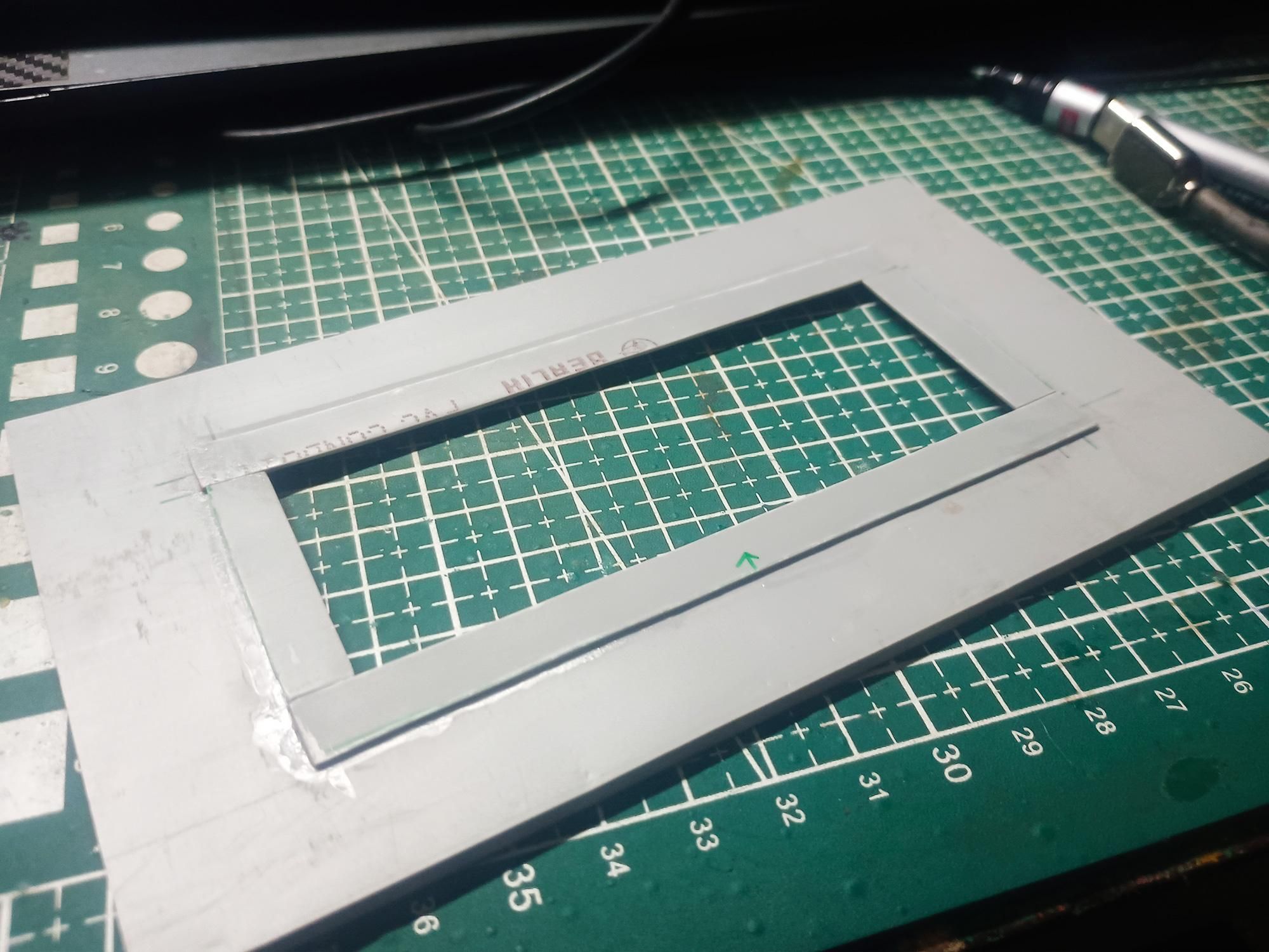
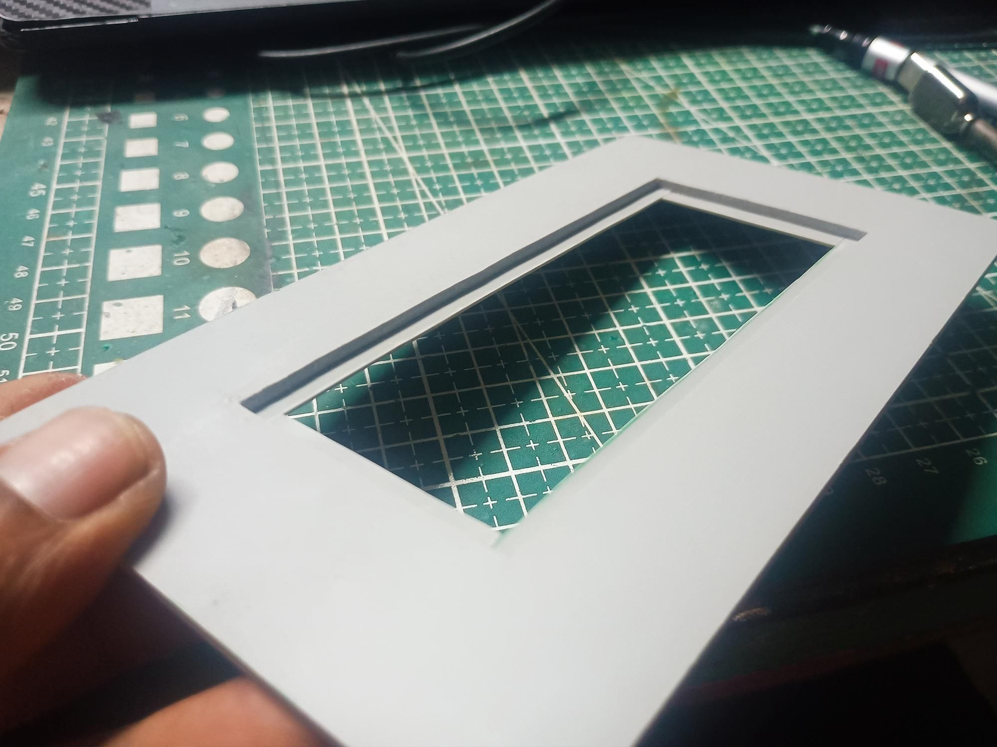
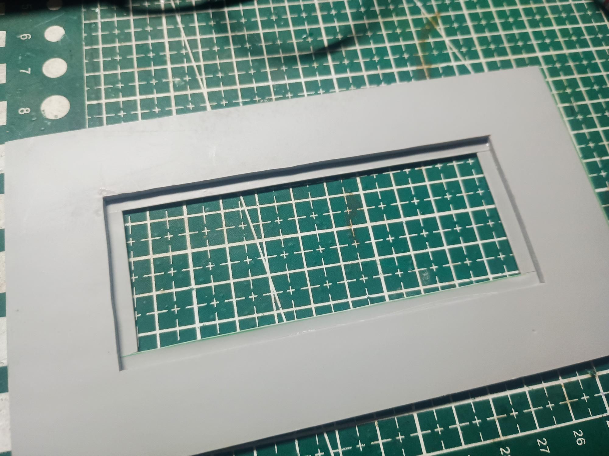
The bottom deck serves as the light engine window. To ensure the clear acrylic cover sits flush, strong, and weather-sealed, we cut out a light aperture and build an internal lip (rabbet frame) using thin PVC strips.
- Marking & Cutting the Main Window:
- Layout: On a piece of flattened PVC sheet mark out a central light aperture (110mm x 45mm) leaving an even border around the edges.
- Scroll Saw Cutout: Drill a small starter hole inside the waste area, feed your scroll saw blade (or fret saw) through, and cleanly cut out the central rectangle.
- Clean the Edges: Use a flat needle file or 240-grit sandpaper to smooth out the interior cut edges until straight and square.
- Fabricating the Internal Acrylic Lip:
- Structure: Instead of routing a groove, build a clean structural ledge (recess rim) on the inside face using thin PVC strips:
- Cut Support Strips: Cut 4 thin strips of PVC sheet (2 long sides, 2 short sides) approximately 6-8mm wide.
- Dry Fit: Position the strips along the back perimeter of the window cutout, allowing them to overhang the inner edge by 2-3mm. This overhang creates the ledge that the clear acrylic sheet will rest on.
- Glue in Place: Apply Superglue along the border strips and press them firmly against the main frame.
Fabricating the LED Mounting Panel
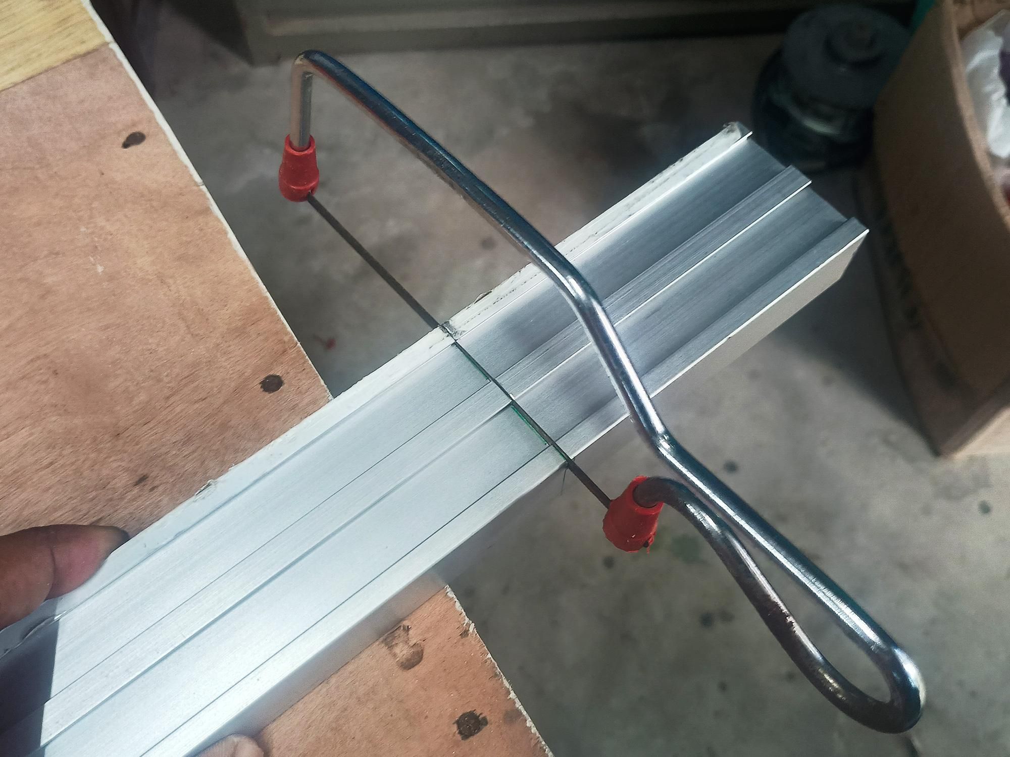
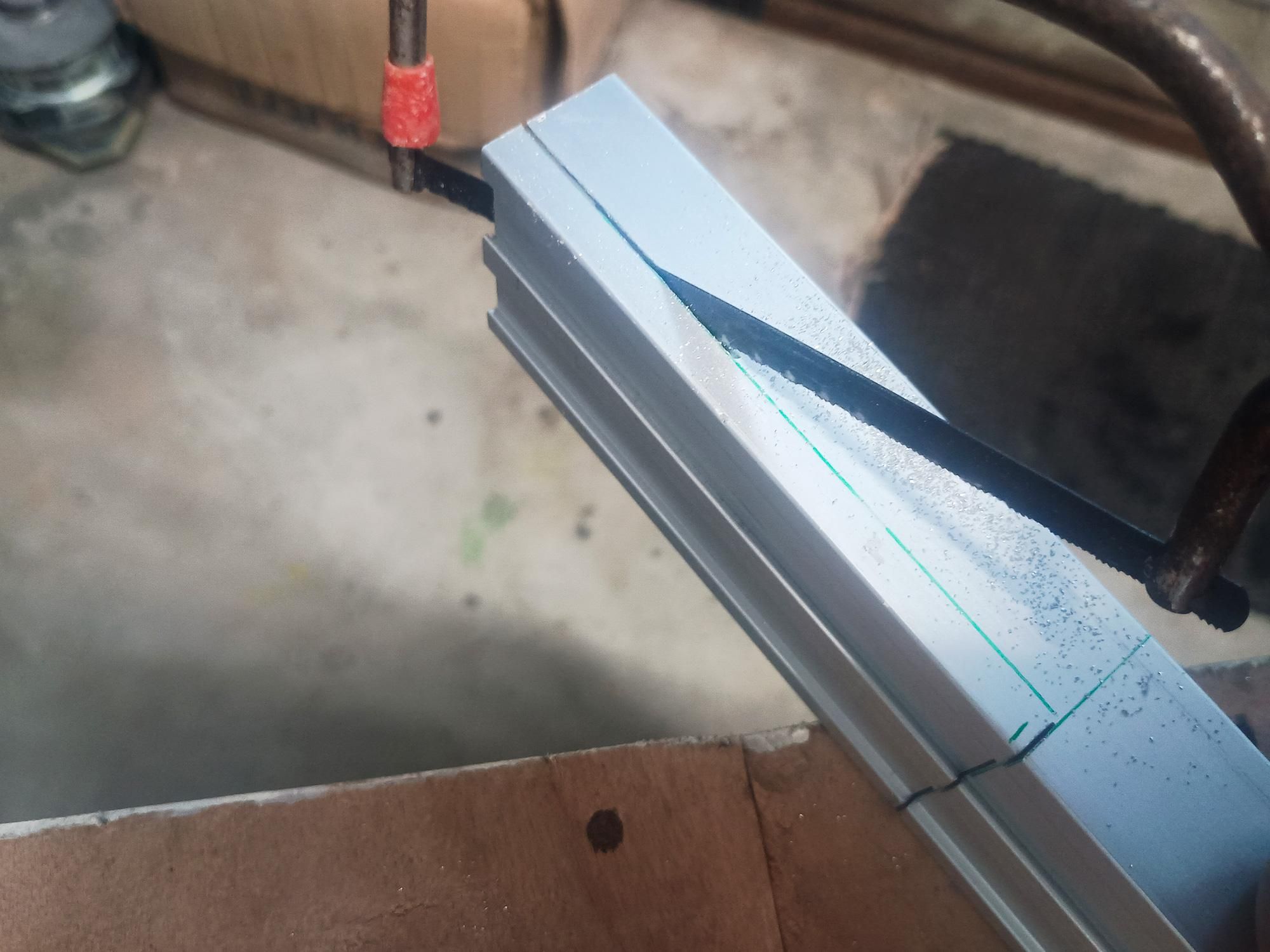
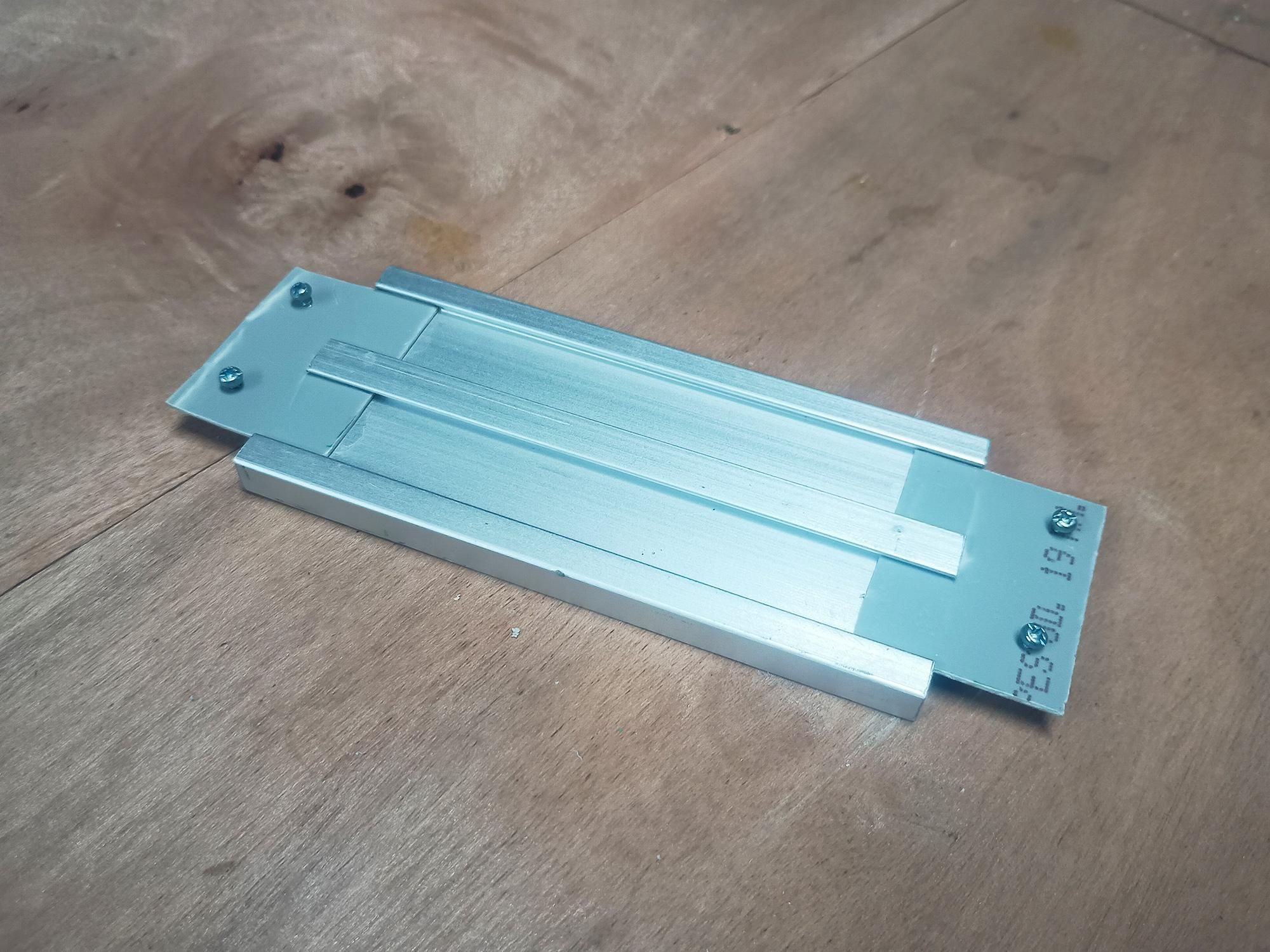
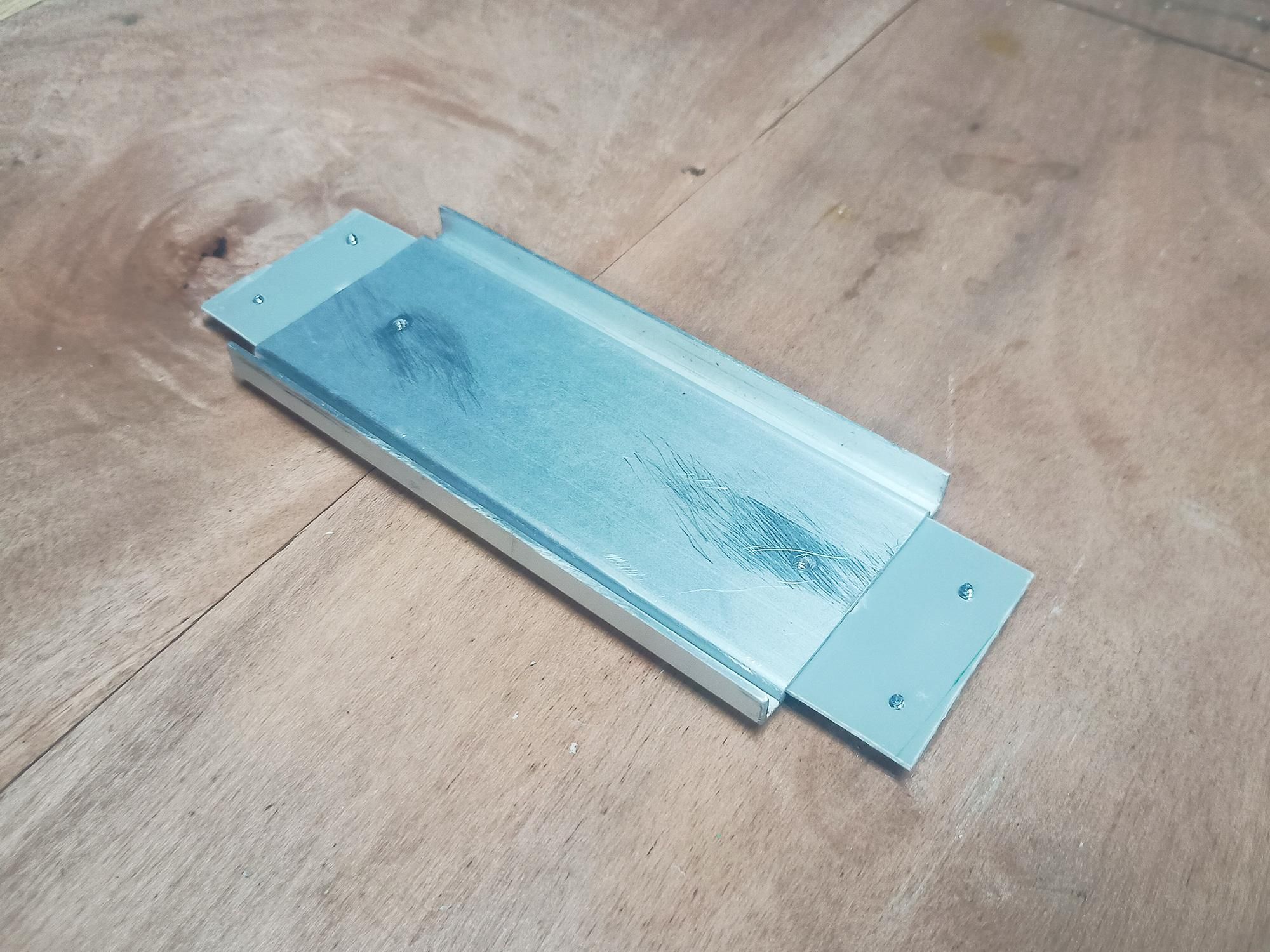
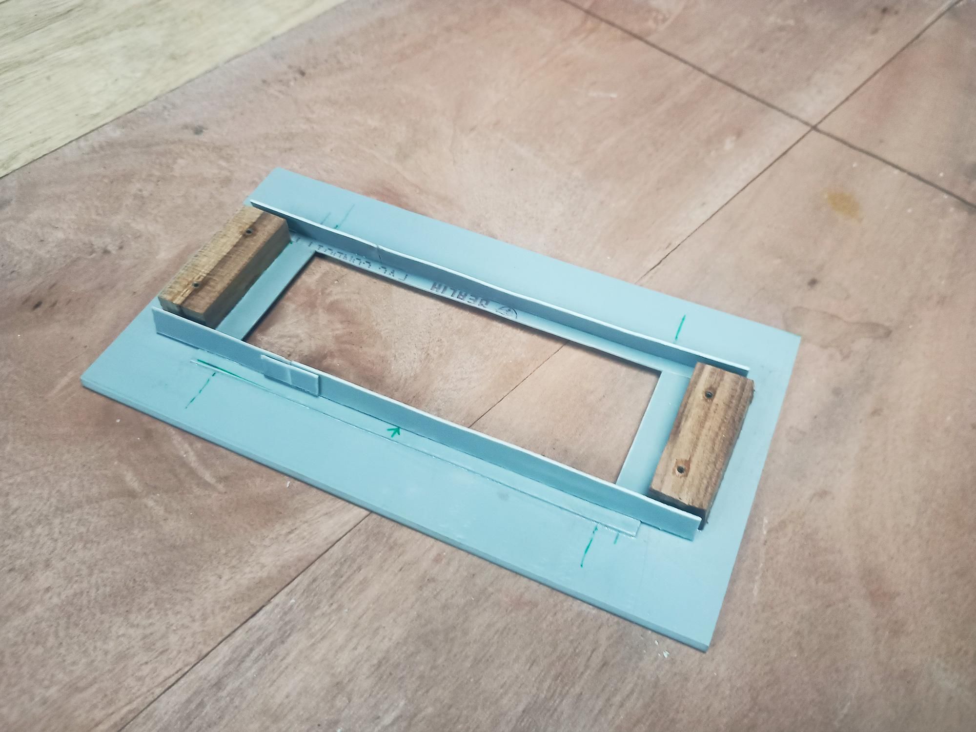
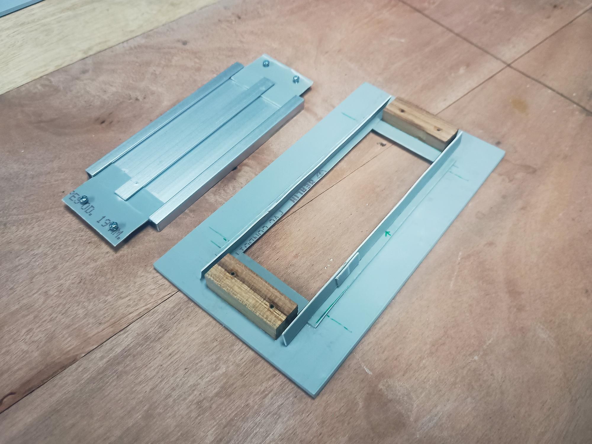
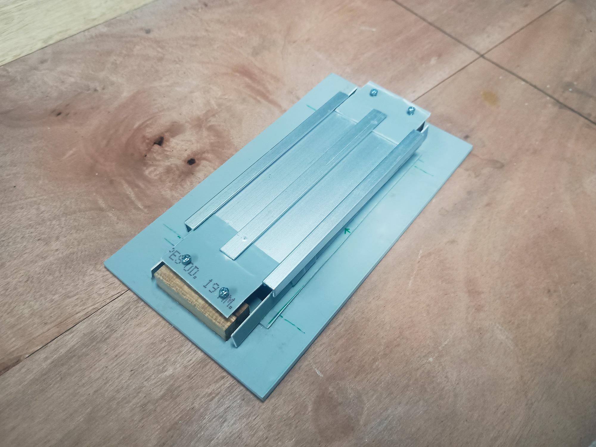
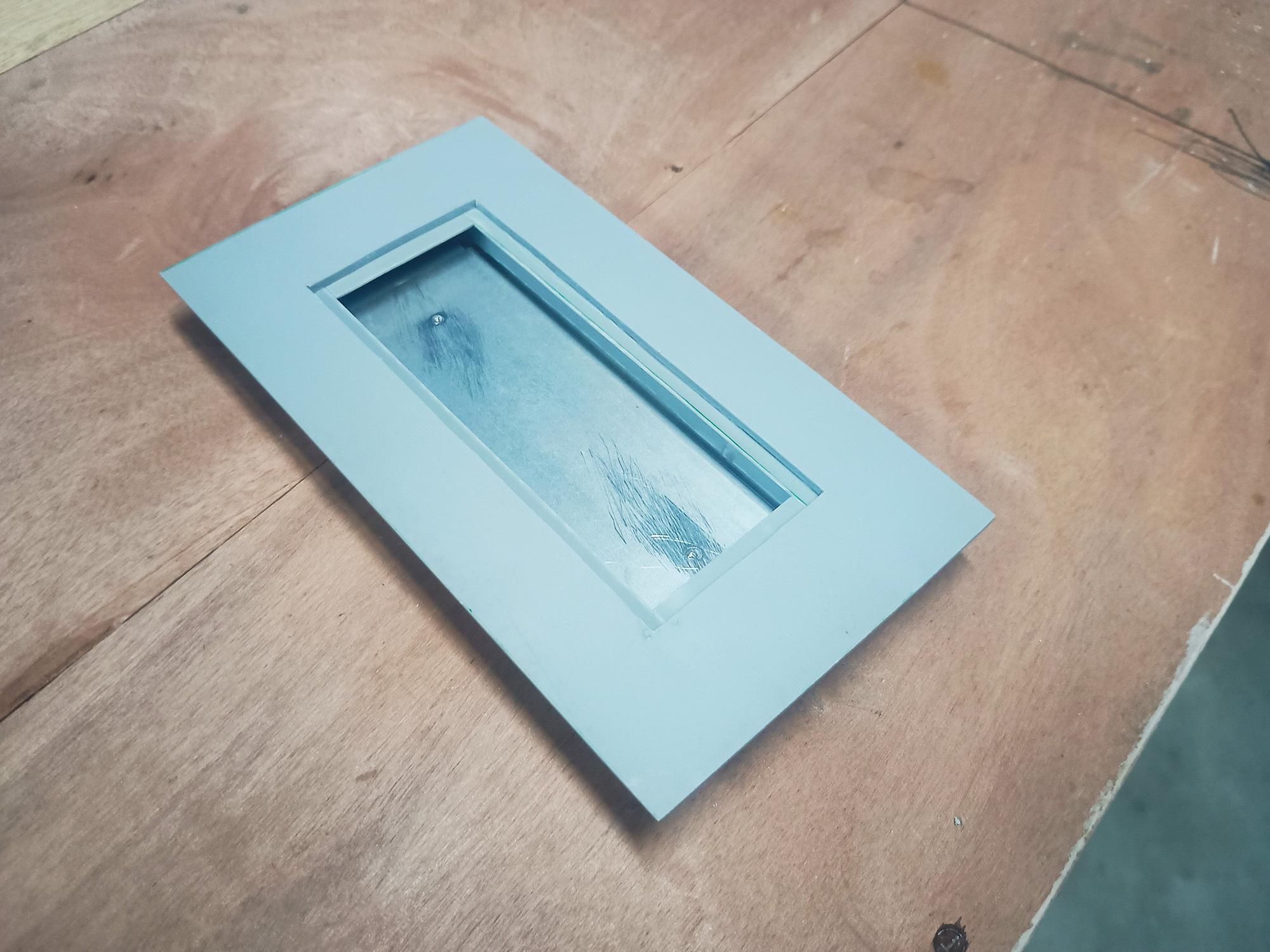
High-brightness LEDs generate heat during operation. To ensure long LED lifespan and optimal efficiency inside a closed PVC enclosure, we construct a dedicated aluminum heatsink plate mounted onto a raised structural PVC tray with wooden anchor blocks.
- Cutting the Aluminum Heatsink Profile:
- Cutting Aluminum: Using a hand hacksaw or coping saw, cut an aluminum section/channel to fit cleanly inside your bottom window recess.
- Trimming Edges: Notch the ends of the aluminum profile so it bridges across the internal window cutout opening smoothly.
- Sanding the Thermal Surface: Lightly sand the flat face of the aluminum plate with 240-grit sandpaper to remove oxidation and ensure maximum thermal contact when gluing or screwing down your 4V LED PCB.
- Preparing the Base Frame & Wooden Spacers:
- Adding Wooden Anchor Blocks: Glue two hardwood mounting blocks on opposite ends of the internal bottom window frame.
- Function of Blocks: These wooden blocks elevate the heatsink plate slightly off the acrylic lens and provide solid material for small wood screws to bite into without breaking through the outer PVC shell.
- Assembling the Removable LED Heatsink Tray:
- PVC Plate Base: Cut a rectangular strip of flattened PVC slightly longer than the aluminum heatsink profile to act as the carrier base plate.
- Securing Aluminum to PVC: Fasten the aluminum channel onto the PVC carrier plate using small counter-sunk screws or thermal epoxy.
- Mounting the Assembly: Prepare the aluminum heatsink tray over the wooden anchor blocks on the bottom window frame and secure it using 4 small wood screws (2 on each side).
Pro Tip: Using small screws to mount the heatsink tray to the wooden blocks makes the entire LED assembly removable, allowing for easy maintenance, repairs, or future LED upgrades without destroying your PVC enclosure!
Assembling Main Enclosure Frame & the Battery Holder Mount
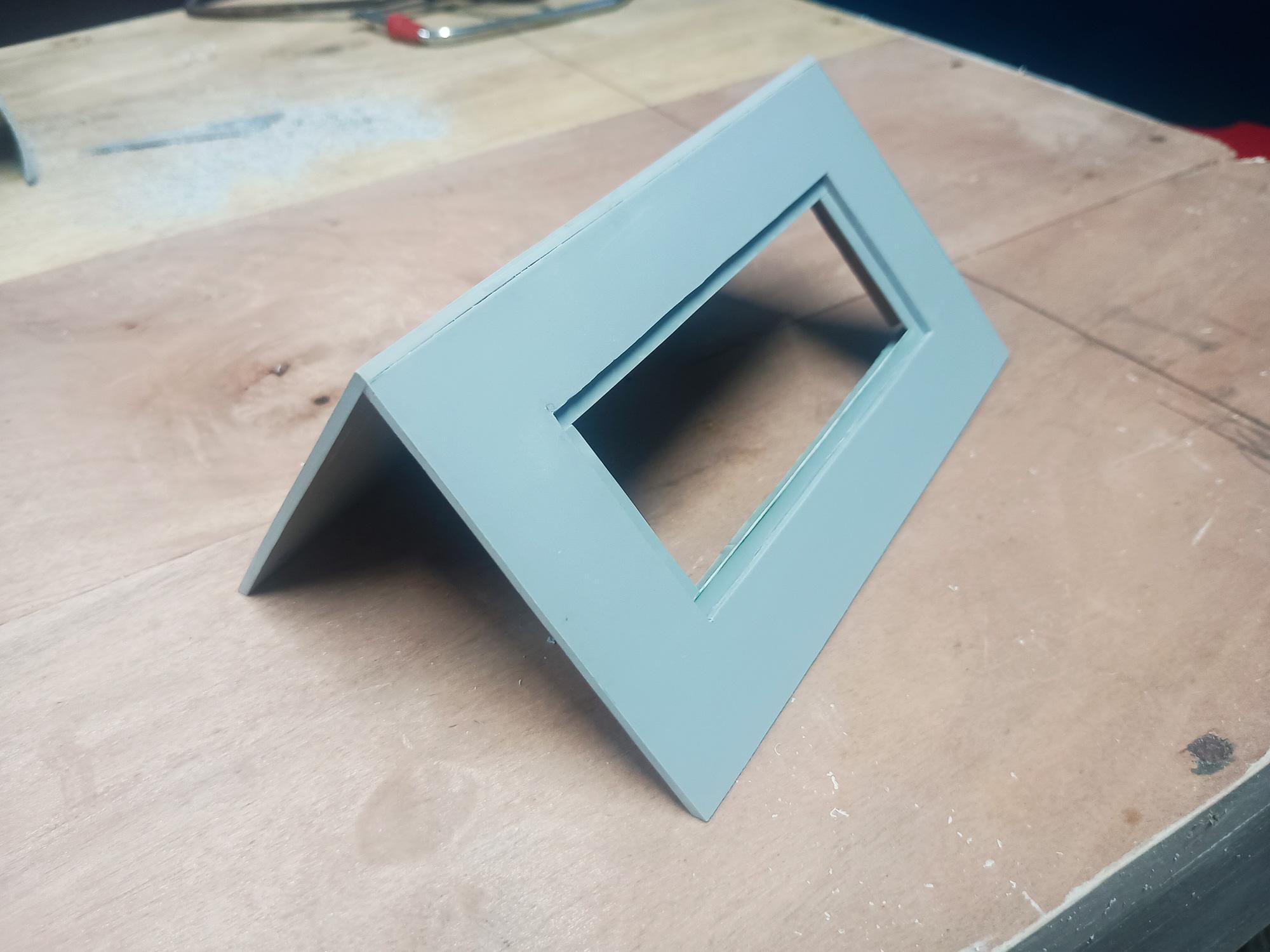
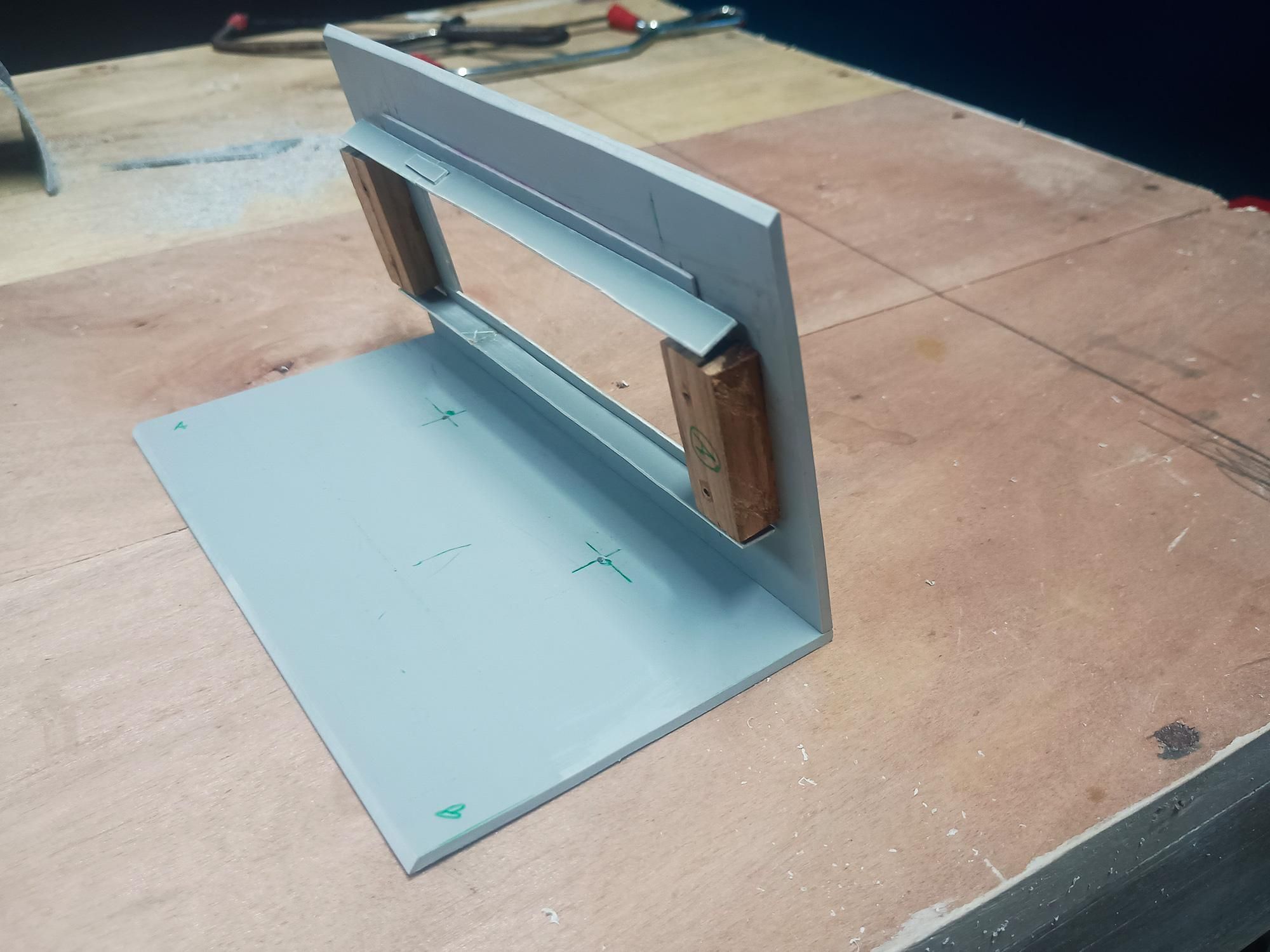
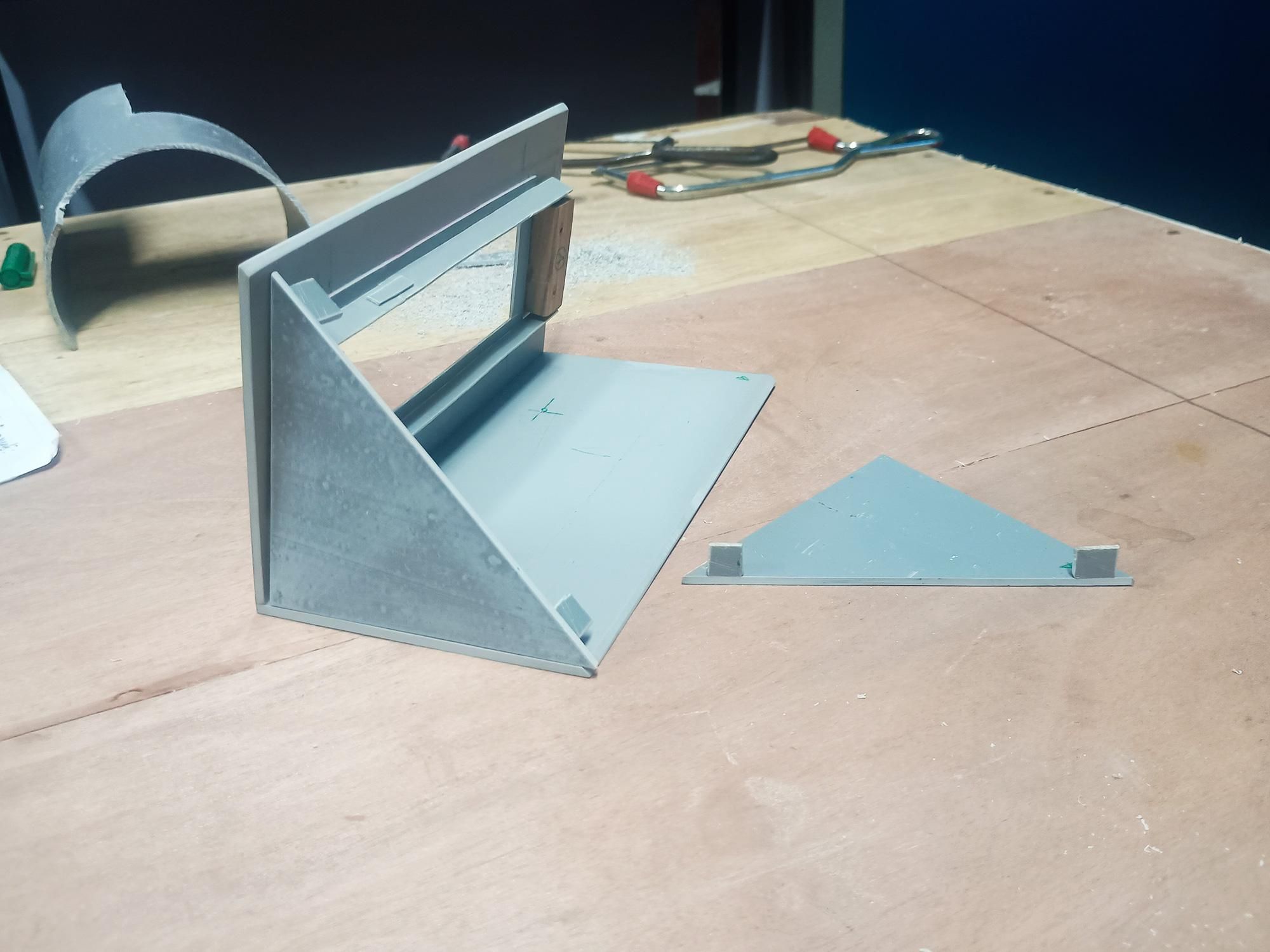
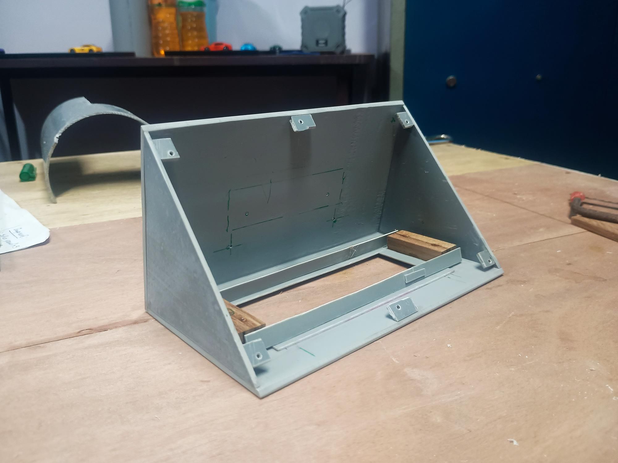
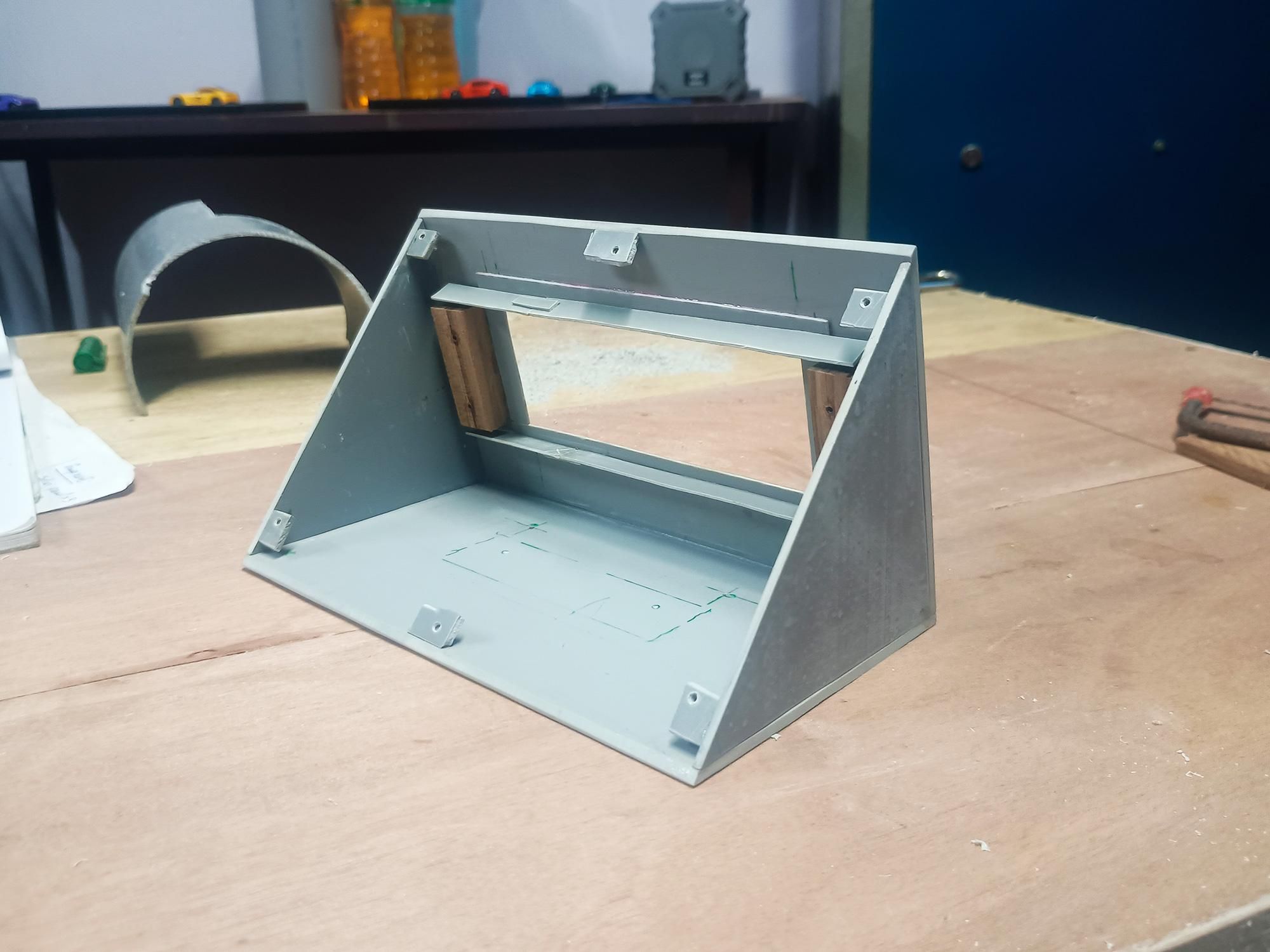
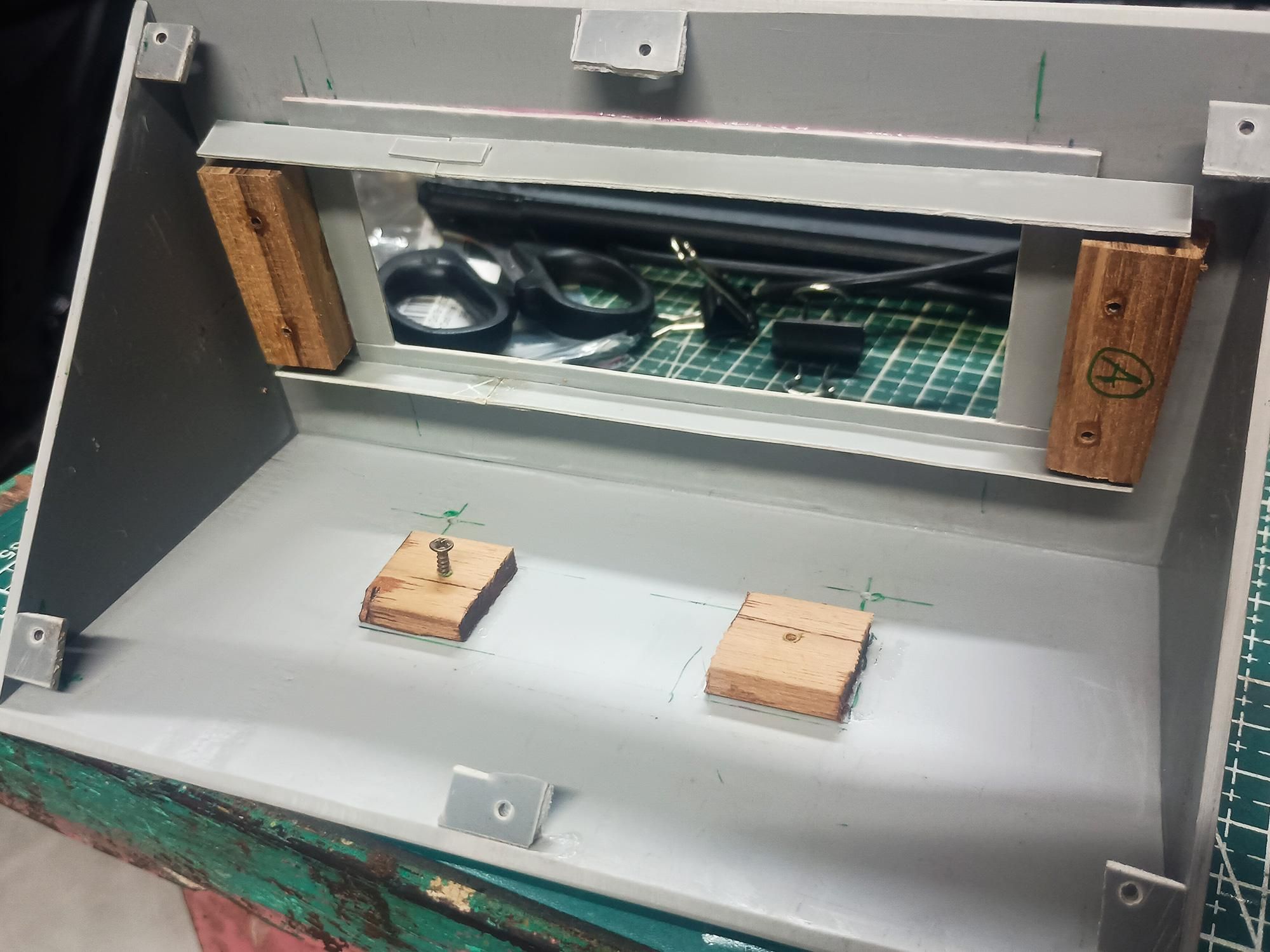
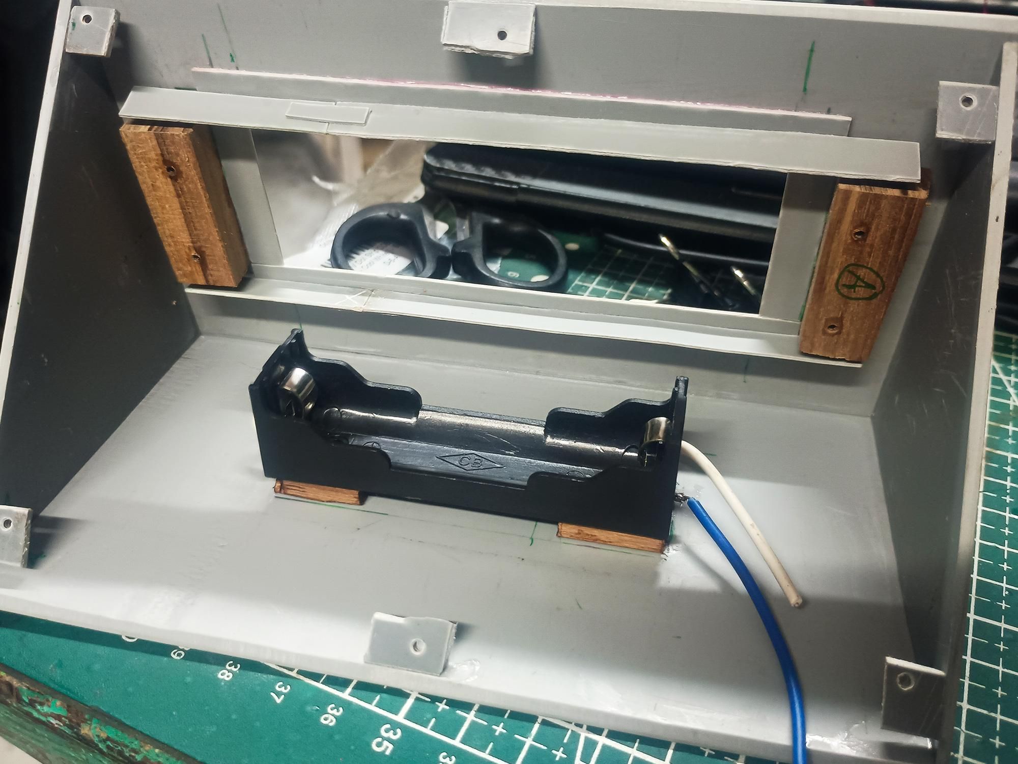
With the individual PVC plates cut and trimmed, we assemble the main structural shell, add interior mounting tabs for a removable back plate, and secure the battery holder to the internal base plate.
- Joining the Front Light Window & Sloped Top Deck:
- Right-Angle Join: Glue the front window plate (housing the acrylic cutout and wooden LED blocks) perpendicularly onto the top sloped PVC deck using strong superglue.
- Checking Squareness: Ensure a tight, seamless 90degree joint between the window face and top deck before the adhesive fully sets.
- Installing the Triangular Side Walls:
- Side Alignment: Fit the two triangular PVC side panels along the side profiles of the assembly.
- Structural Bonding: Glue the side walls along both interior seams (joining the front window plate and the top sloped deck) to form a rigid, hollow wedge enclosure.
- Adding Internal Corner Mounting Tabs:
- To make the rear backplate removable for easy wiring and battery replacement, glue small PVC tabs with pre-drilled screw pilot holes around the interior perimeter:
- Fabricating Tabs: Cut small rectangular tabs (7mm x 10mm) from leftover PVC sheet and drill a 2mm pilot hole through each center.
- Placement: Glue 6 tabs around the interior rear edges—two on the top edge, two along the bottom plate, and one on each side wall—recessed just enough so the rear cover plate sits flush against the back frame.
- Installing the Wooden Battery Mounts & Holder:
- Wooden Spacer Blocks: Glue two thin wooden spacer blocks onto the center of the inner base plate.
- Why? Elevating the battery holder slightly off the base prevents water accumulation underneath and provides solid wood for the mounting screws to bite into.
- Securing the Battery Holder: Align your 18650 Li-ion battery holder over the wooden blocks and lock it in place using small wood screws.
- Routing Wires: Direct the positive (white/red) and negative (blue/black) battery leads toward the upper electronics area where the charging controller will be mounted.
Pro Tip: Using wood blocks and small screws for the battery holder allows you to replace or upgrade the battery housing in the future without tearing apart the glued PVC shell!
Mounting Solar Panels & Internal Wire Management
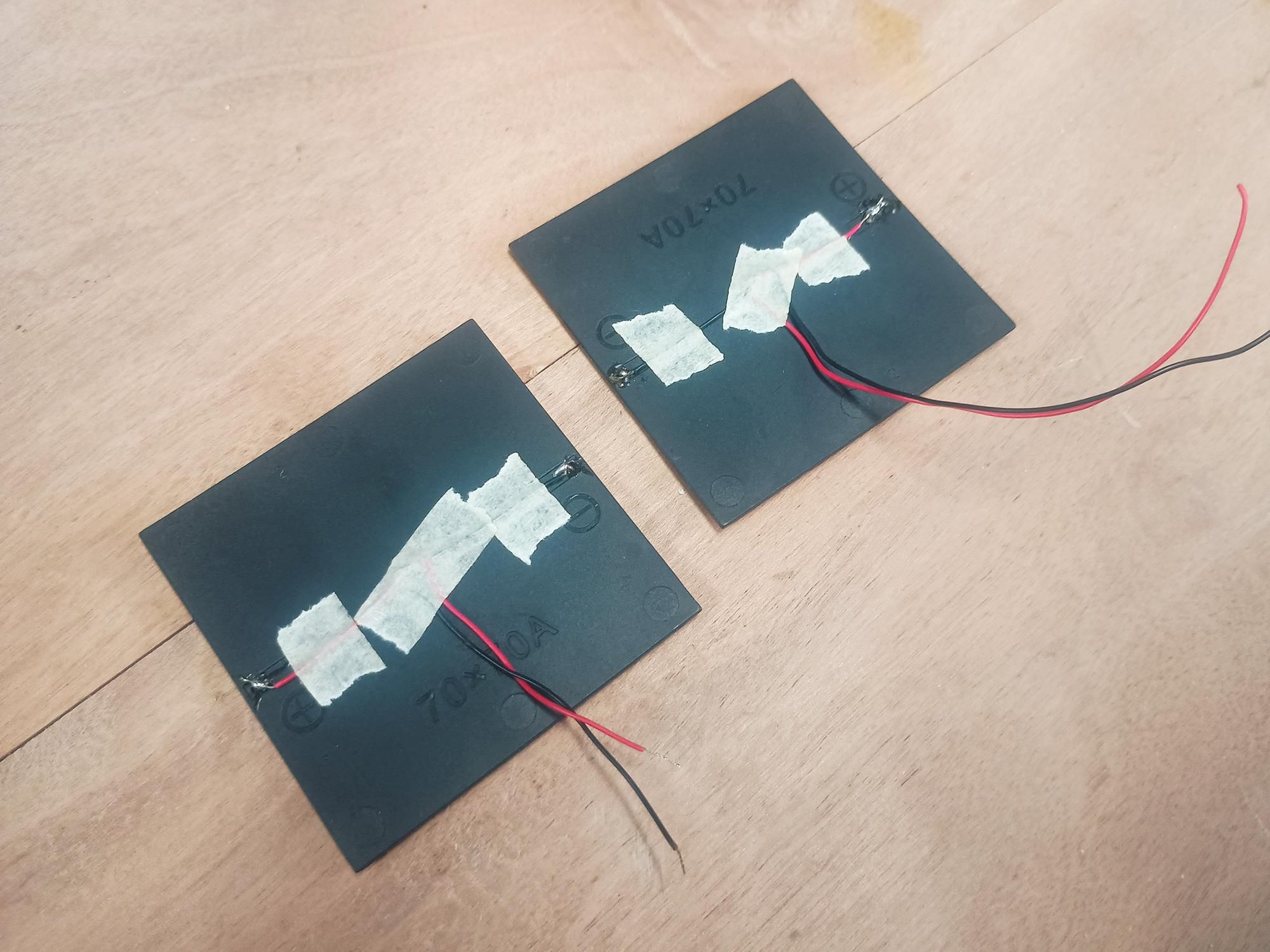
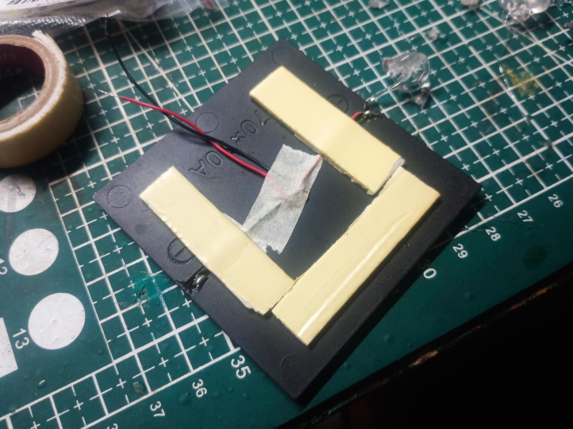
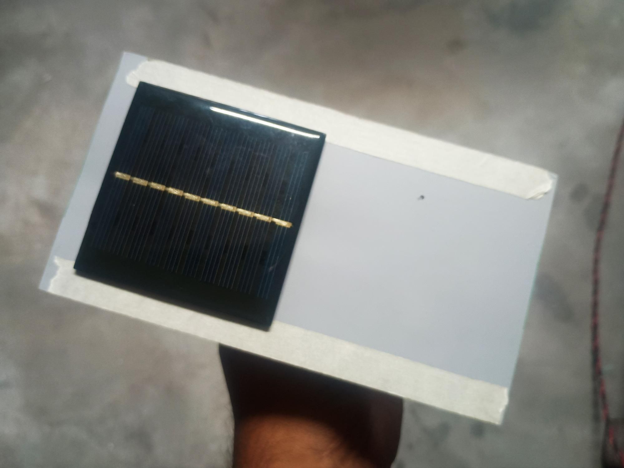
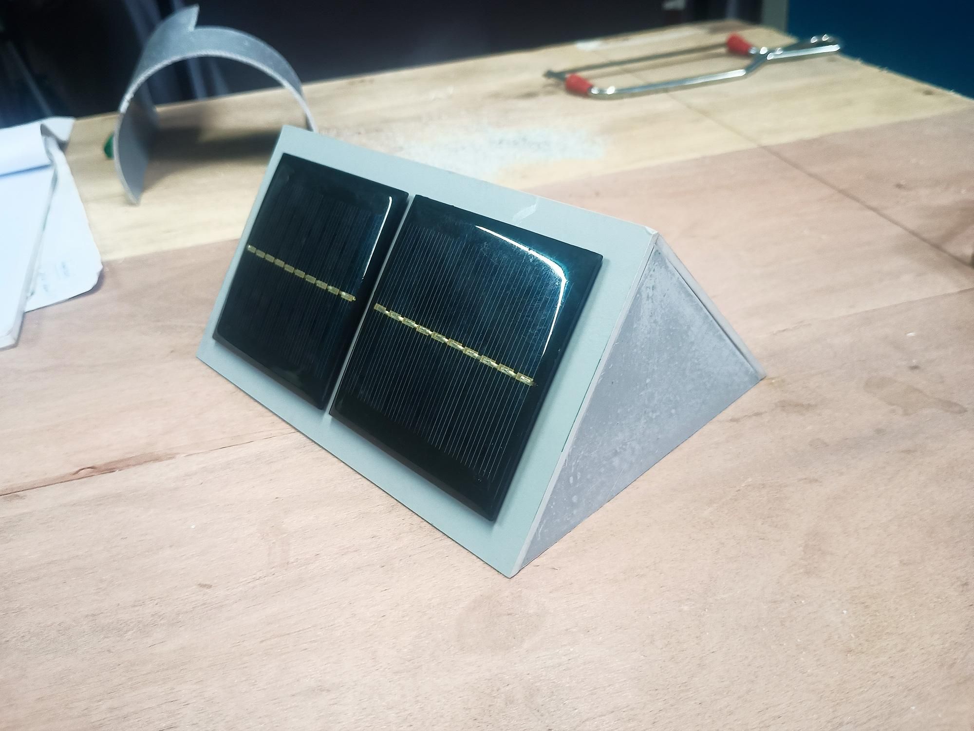
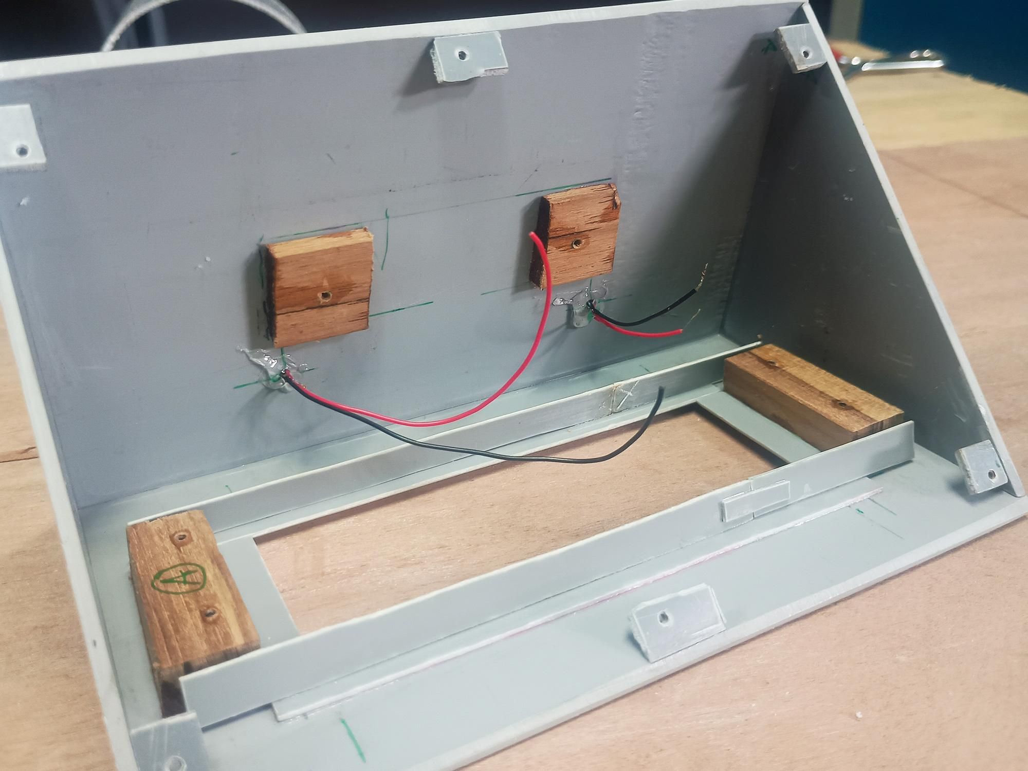
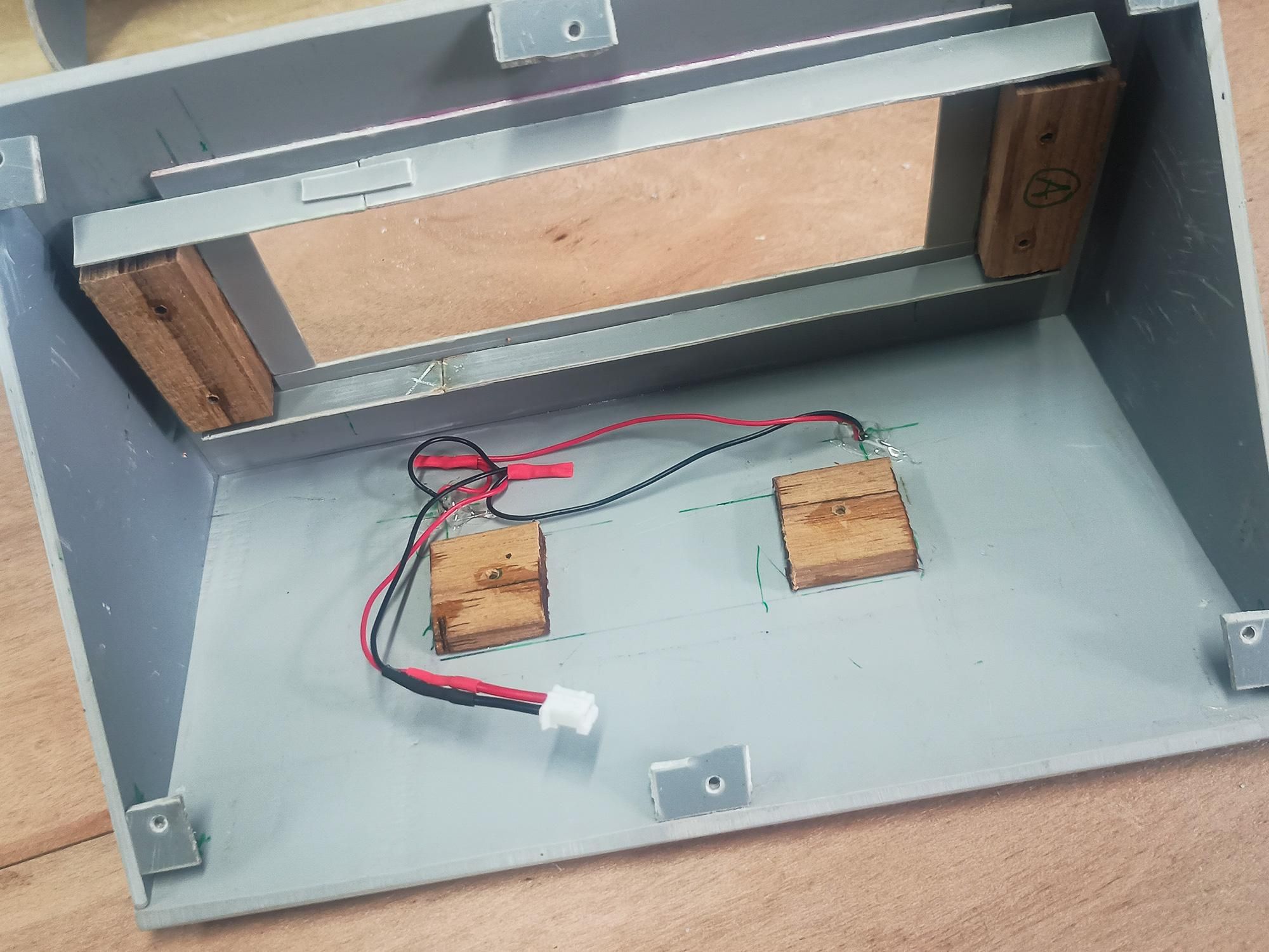
Now that the core body and internal mounting tabs are built, it is time to affix the solar panels onto the top sloped roof and harness their wiring inside the upper hidden chamber.
- Preparing & Mounting the Solar Panels:
- Applying Double-Sided Foam Tape: Apply strips of heavy-duty outdoor double-sided foam tape along the rear perimeter of each solar panel. This creates a strong initial bond while dampening vibrations.
- Pre-wiring Panels: Ensure red (+) and black (−) wires are securely soldered to the rear contact pads of each panel.
- Placing Panels: Pass the wire leads through the pre-drilled feed holes in the top PVC roof deck, then press each solar panel firmly onto the sloped face.
- Masking & Edge Sealing: Apply masking tape along the PVC roof borders and around panel edges, then seal all outer seams with a thin bead of clear silicone to prevent rainwater from creeping under the panels.
- Sealing Wire Feed Holes:
- Strain Relief & Waterproofing: Inside the rear chamber, secure the incoming panel wires against the inner PVC wall using a drop of hot melt glue or clear silicone right over the feed holes.
- Benefit: This seals the wire holes from water ingress and prevents accidental wire tugs from breaking the solder joints on the solar panels.
- Parallel Bus Wiring & Connector Termination:
- Parallel Connection: Combine the positive (+) wires from all solar panels together, and repeat for all negative (−) wires to wire the solar array in parallel.
- Insulation: Slide heat-shrink tubing over each soldered joint and apply heat to prevent short circuits against internal components.
- Quick-Disconnect Plug: Terminate the combined solar bus into a 2-pin JST (or similar) quick-connect plug.
- Why? Adding a quick-connect plug makes it effortless to plug/unplug the solar array from the main charging controller board during maintenance or testing.
Pro Tip: Keep all internal wire lengths neat and tidy by bundling them along the side walls. Clean wire management prevents loose wires from pressing against the battery or obscuring the LED light path!
Installing LED Assembly & Other Components
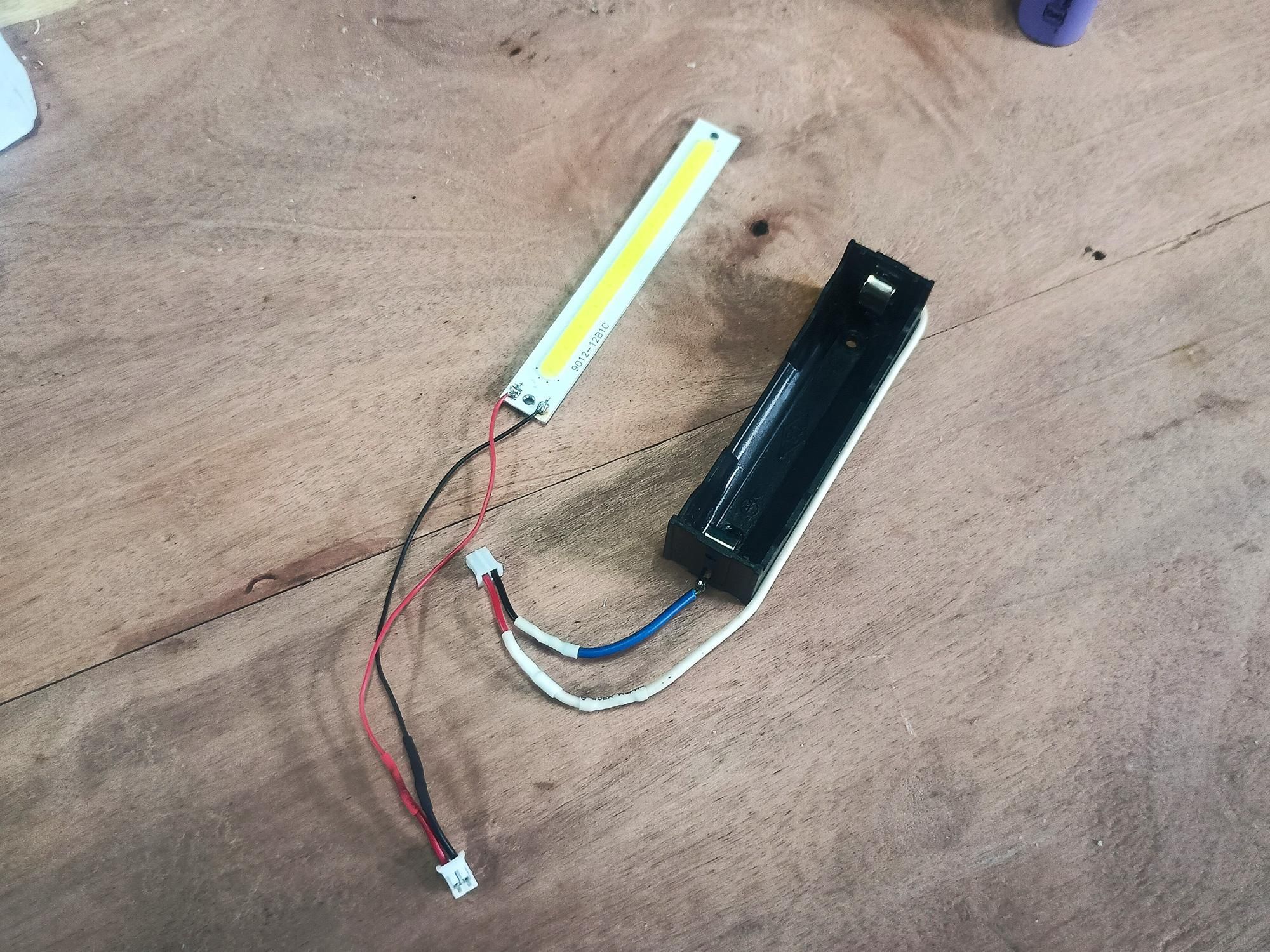
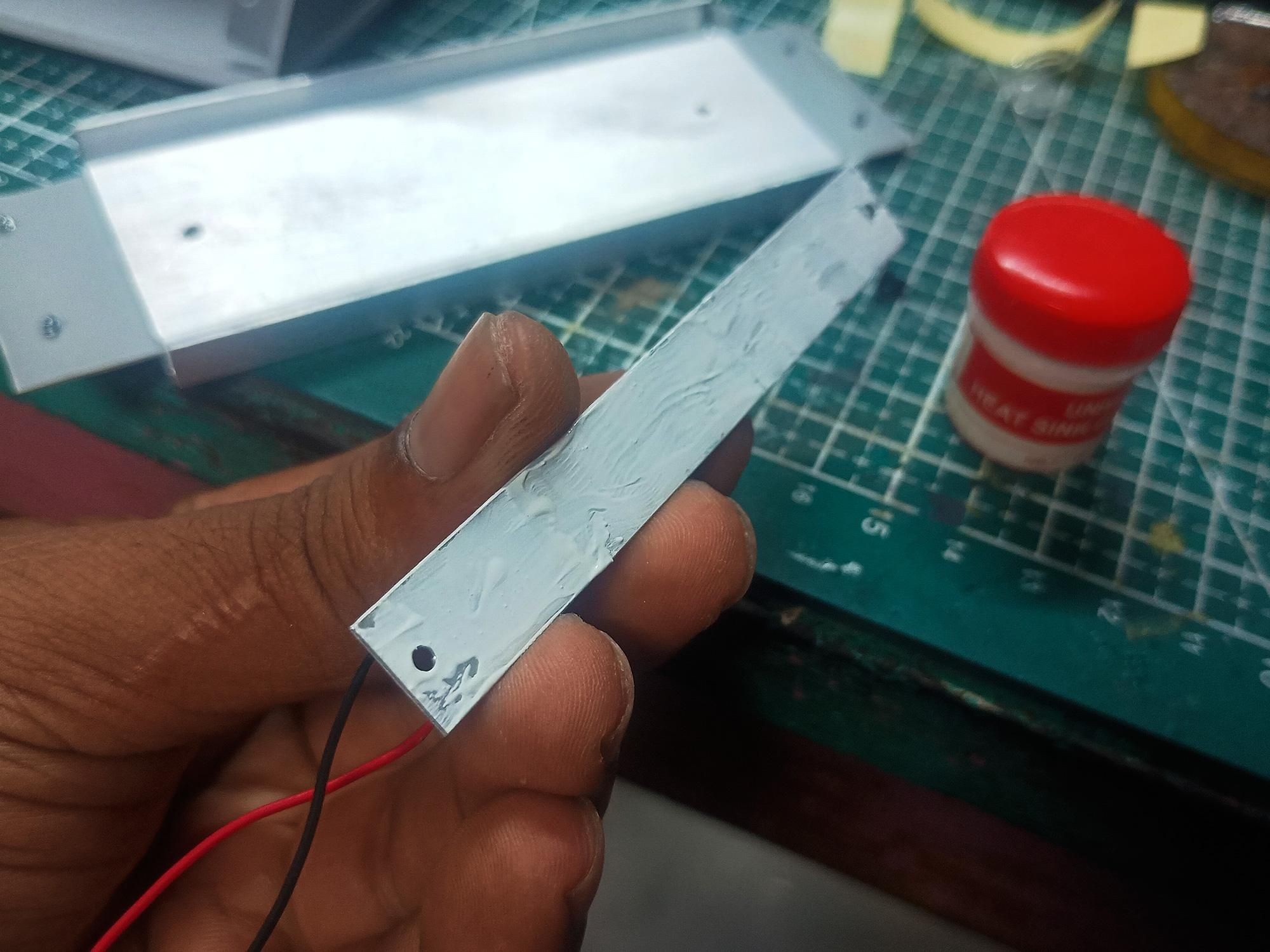
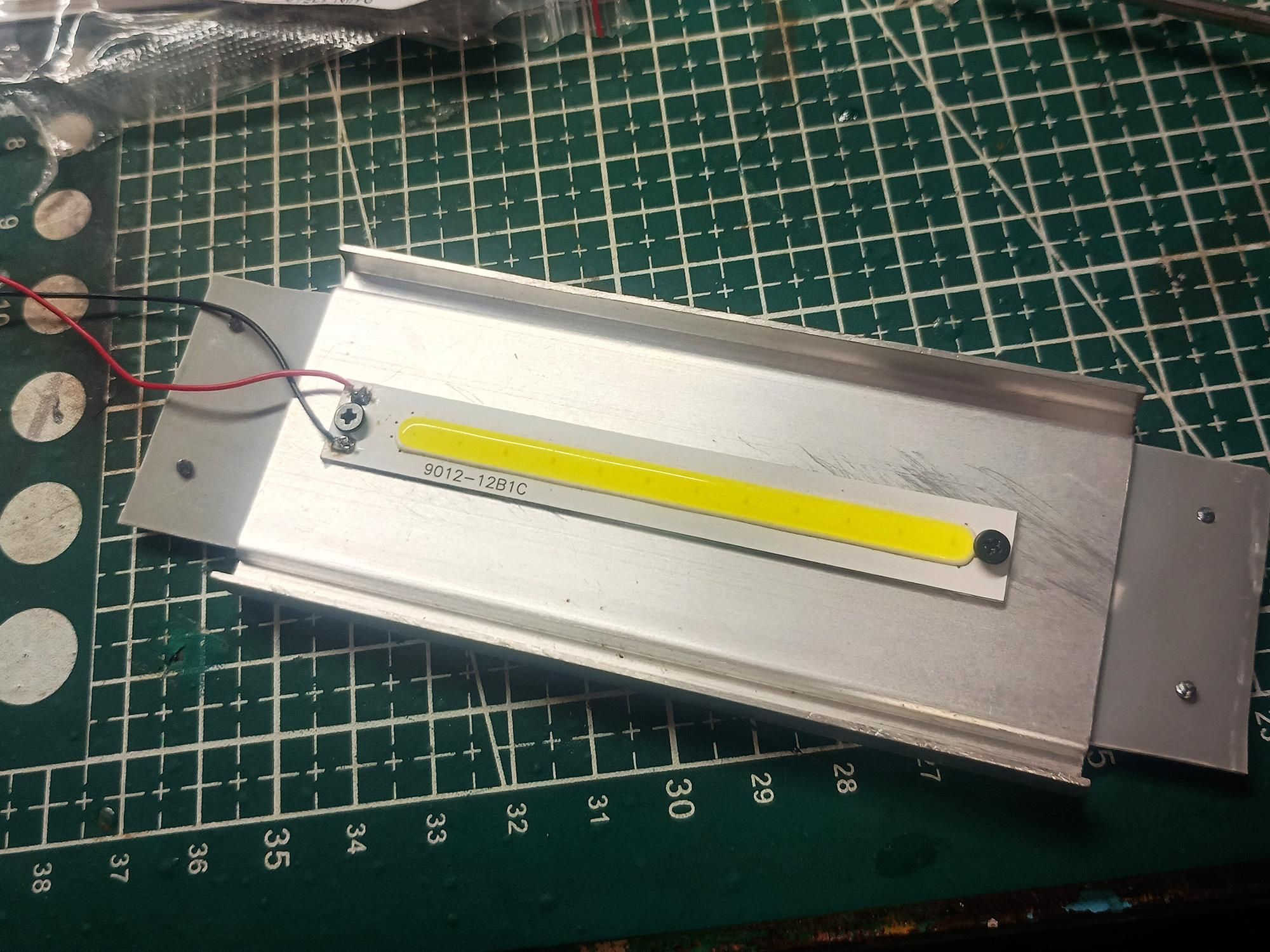
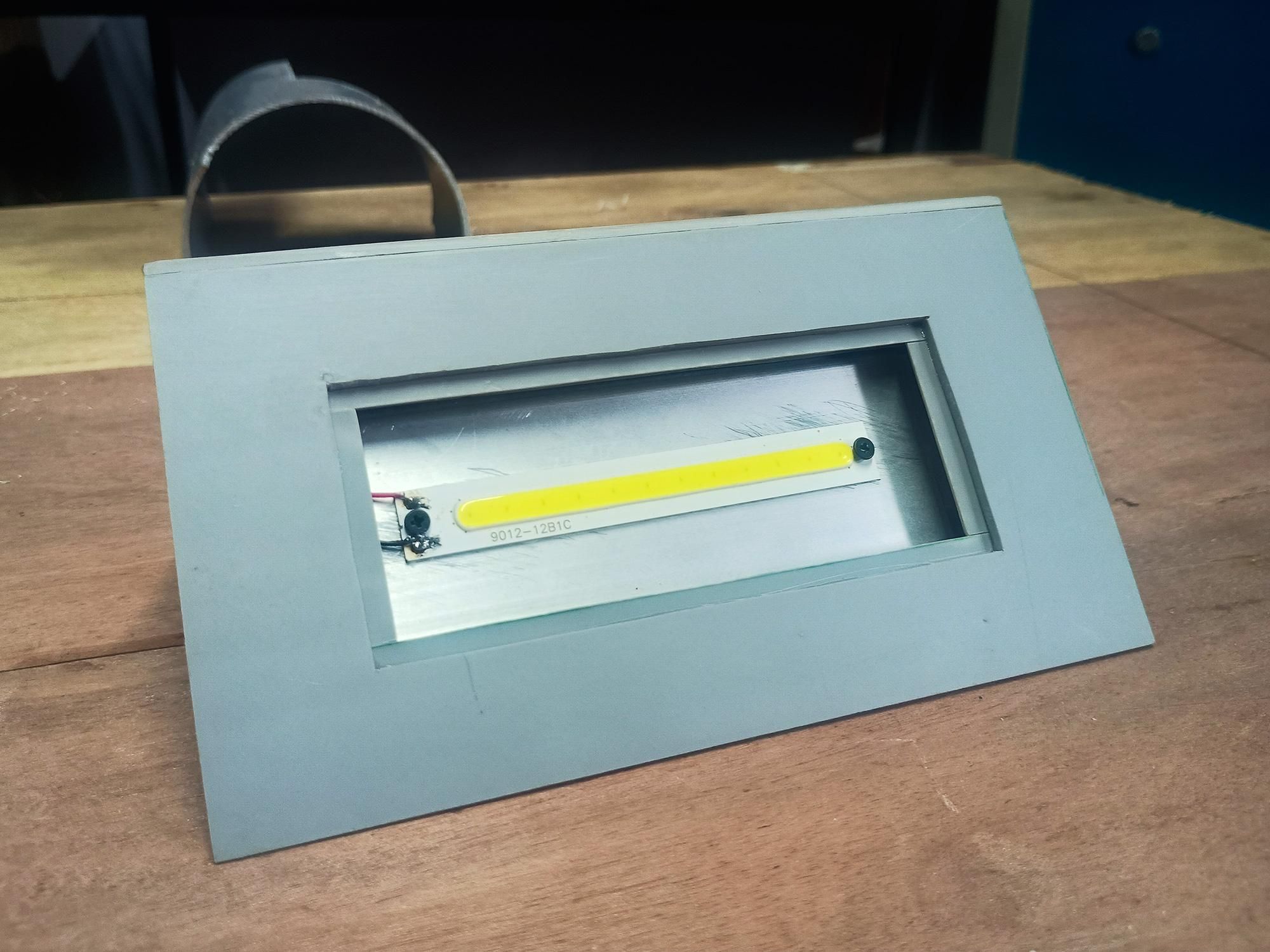
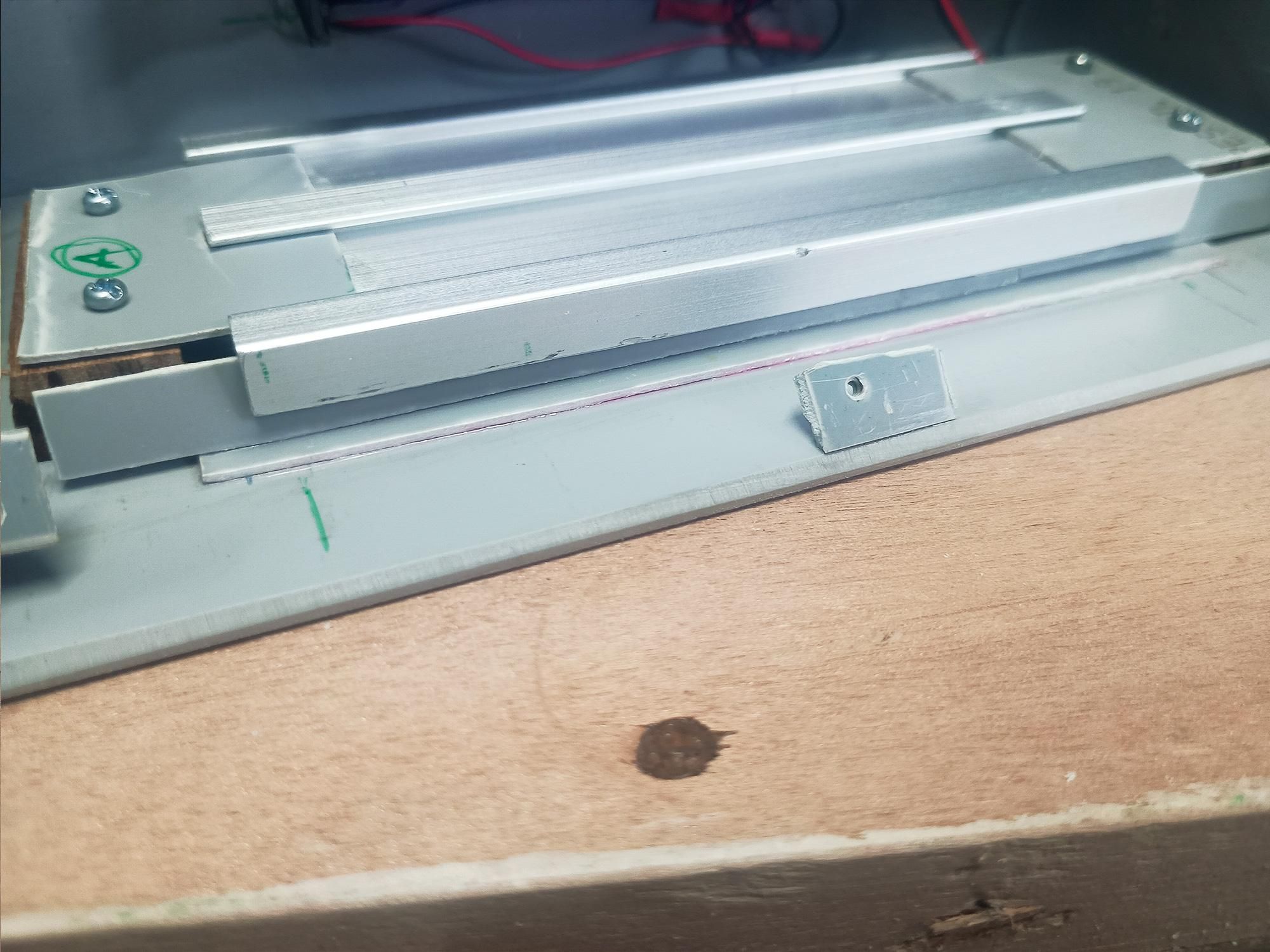
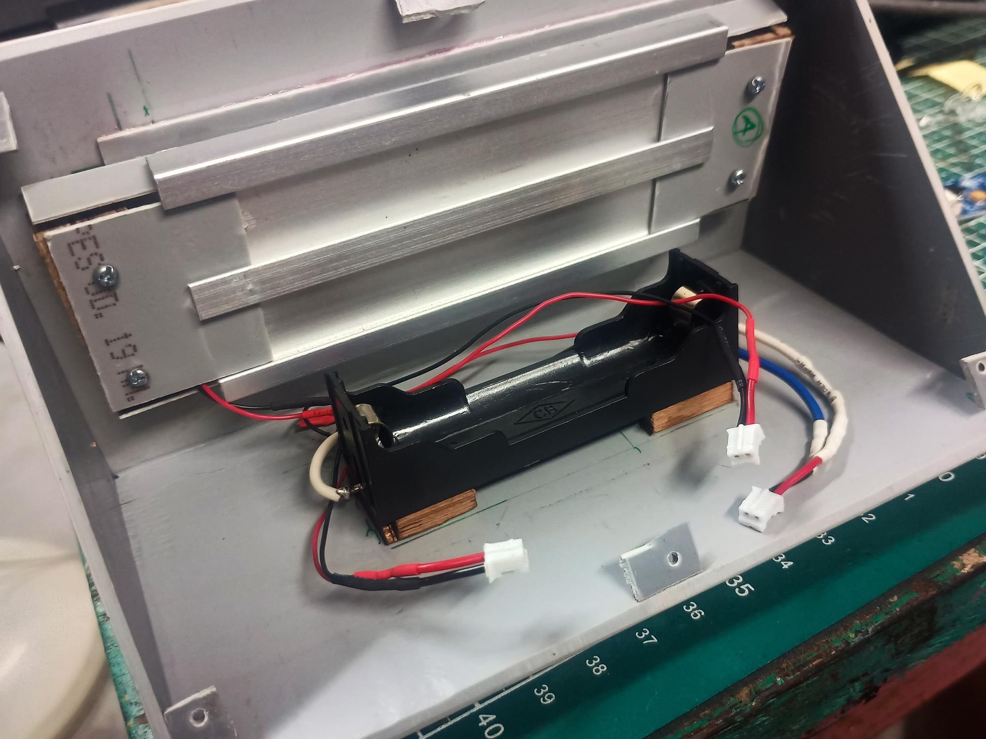
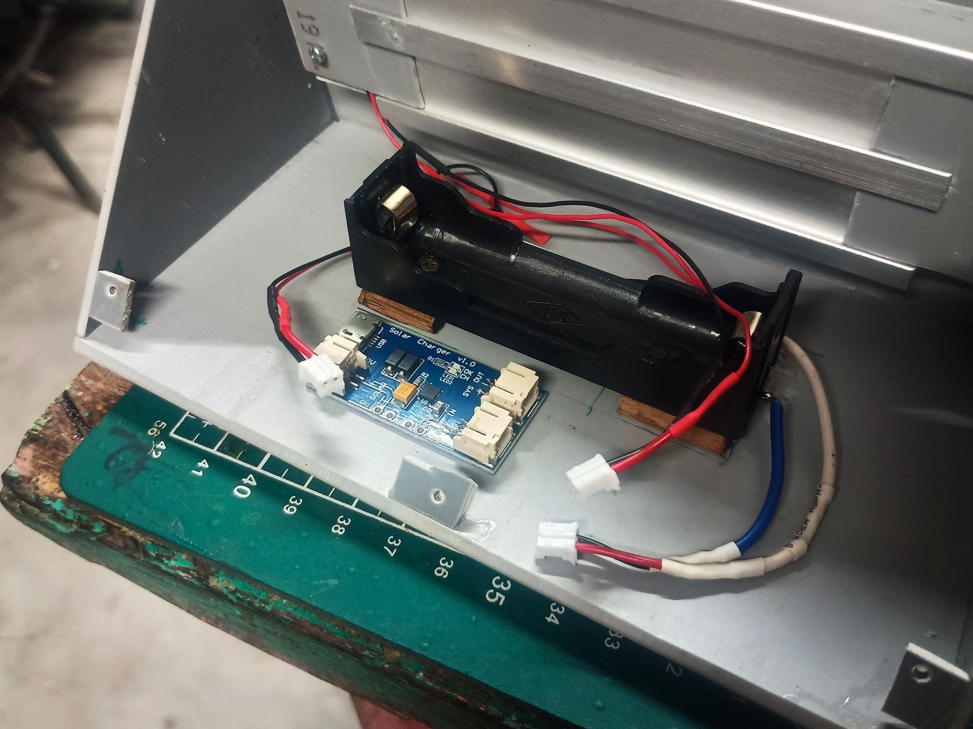
With the main frame constructed, we mount the high-efficiency COB LED strip onto its heatsink using thermal paste, secure the 18650 battery holder, and position the solar charge controller module inside the hidden electronics bay.
- Thermal Paste Application & COB LED Mounting:
- Apply Thermal Compound: Spread an even layer of white thermal heat-sink paste onto the backside of the COB LED strip.
- Why? Thermal paste fills microscopic air gaps between the LED board and the aluminum plate, ensuring maximum heat transfer during long operating hours.
- Screw Down LED: Center the COB LED strip on the aluminum heatsink tray and secure it using small screws at both ends.
- Mount Heatsink Tray: Fasten the entire aluminum heatsink tray onto the wooden anchor blocks behind the light aperture using wood screws.
- Mounting the Battery Holder & Controller Board:
- Install 18650 Battery Holder: Secure the battery holder onto the wooden base blocks inside the lower chamber using small wood screws.
- Mount Solar Charge Controller: Place the Solar Charger v1.0 module alongside the battery holder on the bottom inner plate using double-sided foam tape or small nylon standoffs.
- Modular Cable Terminations (JST Plugs):
- To keep the build clean and easy to service, terminate all component wiring with 2-pin JST quick-connect plugs:
- Front Lens & Lighting Check:
- Clear Lens Fitting: Position the clear acrylic protective cover over the recessed front window frame to verify that the COB LED strip sits perfectly centered and visible behind the glass.
Installing the TTP223 Capacitive Touch Switch Module
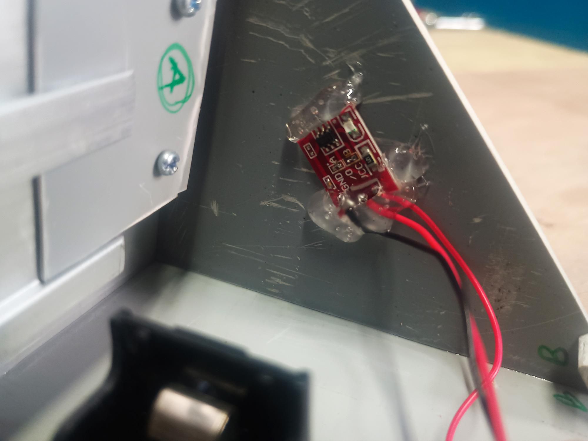
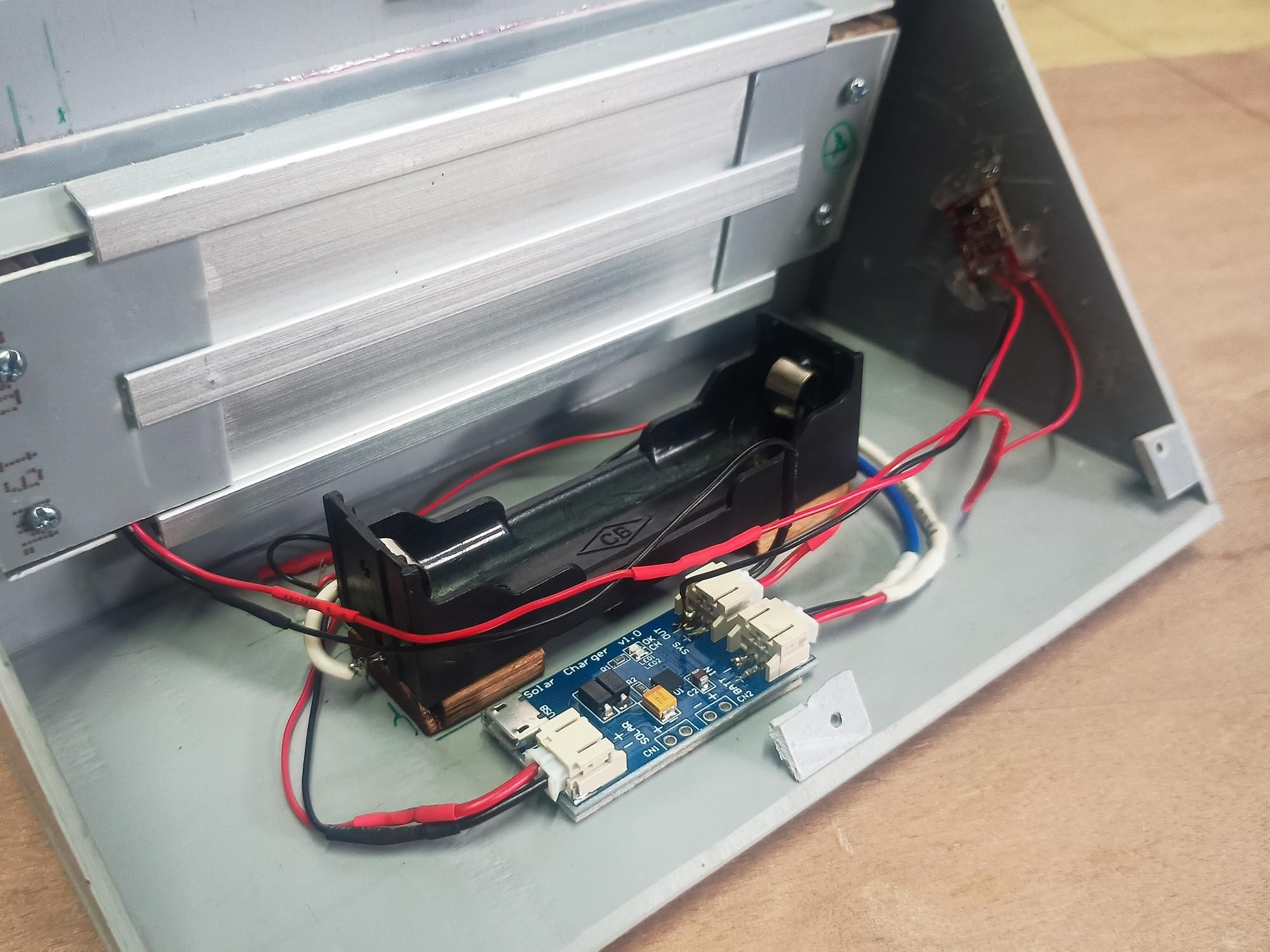
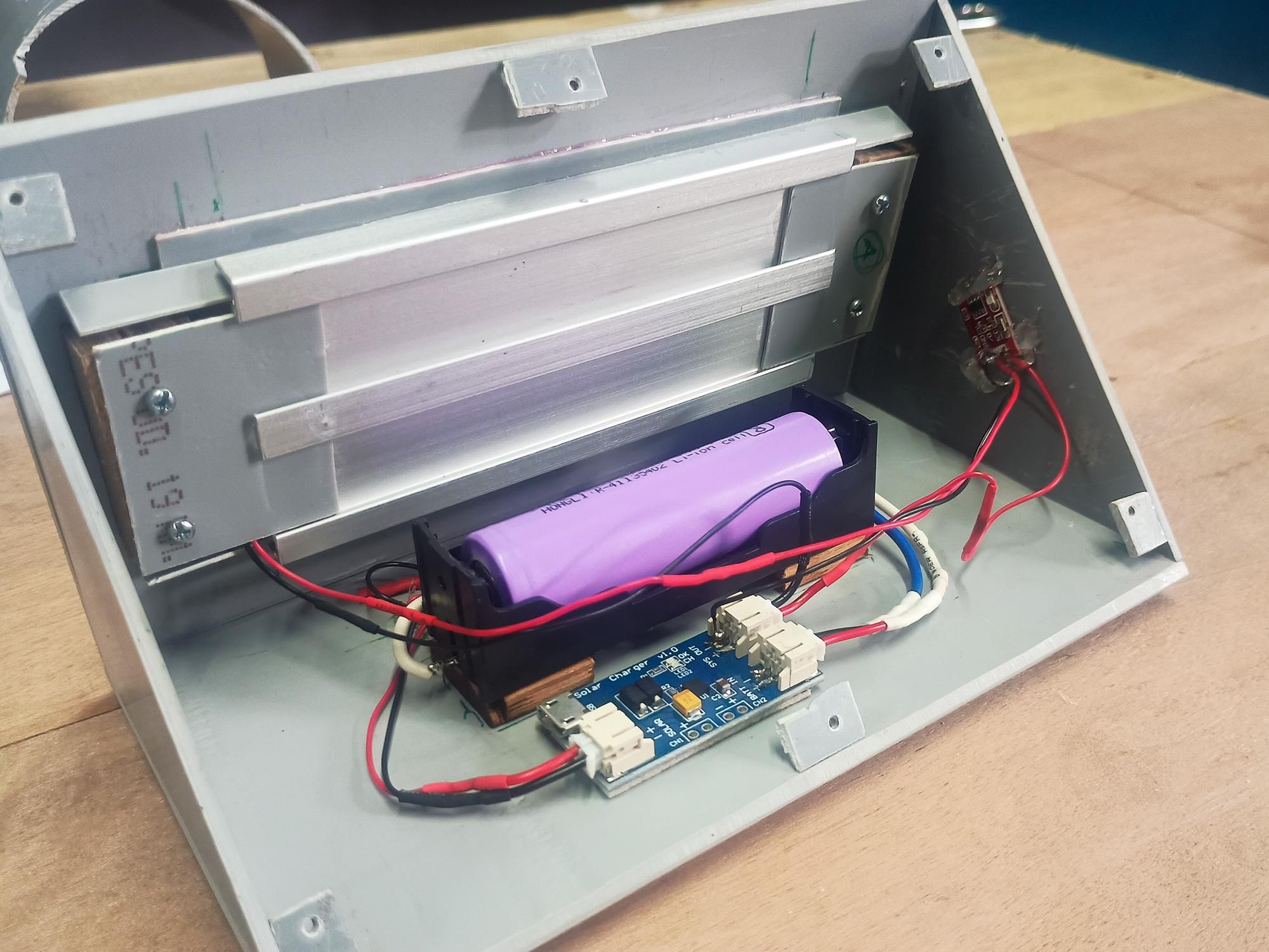
To keep the enclosure completely waterproof and eliminate mechanical switches, we use a TTP223 capacitive touch sensor module. Because capacitive sensors detect touch through non-metallic barriers, the sensor can sit completely concealed on the inside of the PVC wall—allowing you to turn the light on/off simply by tapping the outside of the casing!
- Positioning & Securing the Touch Sensor:
- Choose a Touch Spot: Select a flat, easily accessible spot on the inner side wall of the PVC enclosure.
- Mounting flush against PVC: Place the active sensing face of the red TTP223 module flush against the inside surface of the PVC wall.
- Hot-Glue Fixation: Apply a liberal amount of hot melt glue (or clear silicone) around the edges and back of the module to lock it securely against the PVC panel.
TIP: Making sure there is no air gap between the sensor face and the plastic wall ensures maximum touch sensitivity from the outside.
Final Connections, System Testing & Sealing
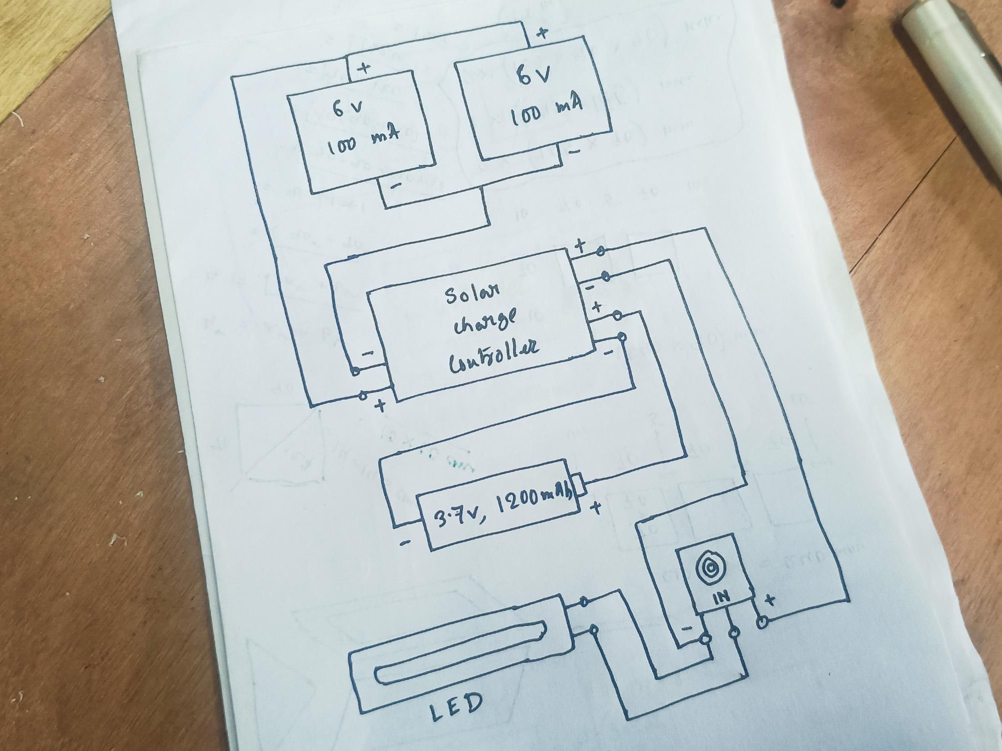
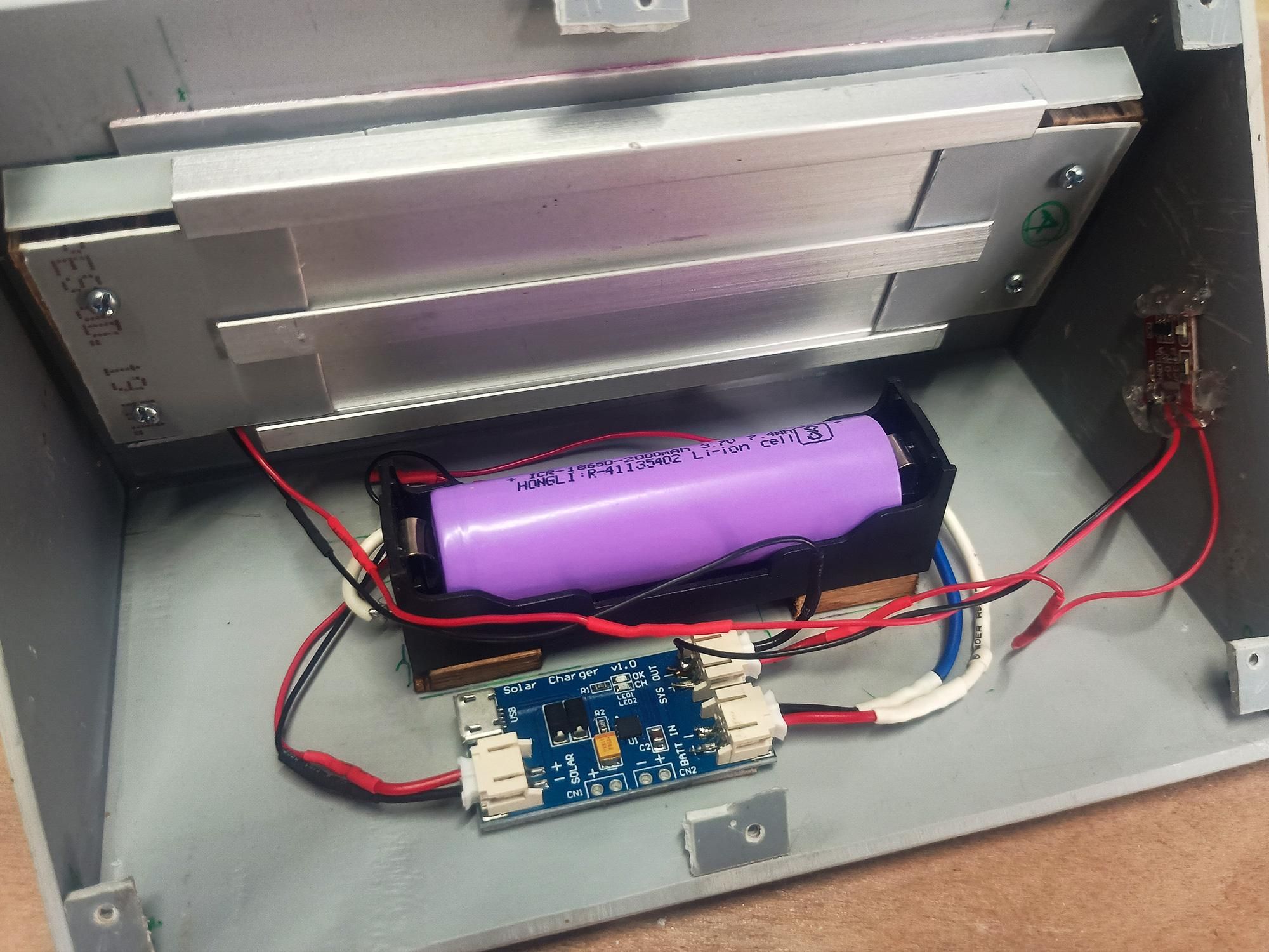
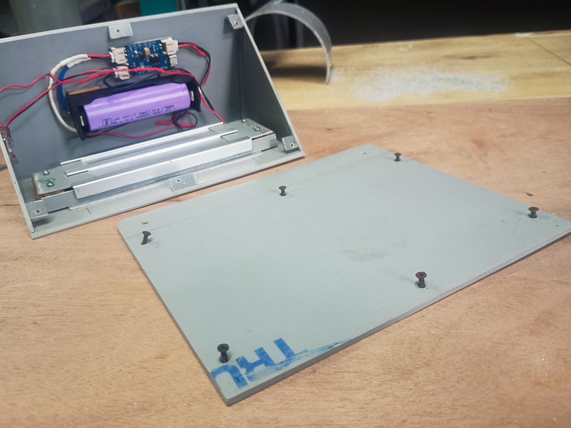
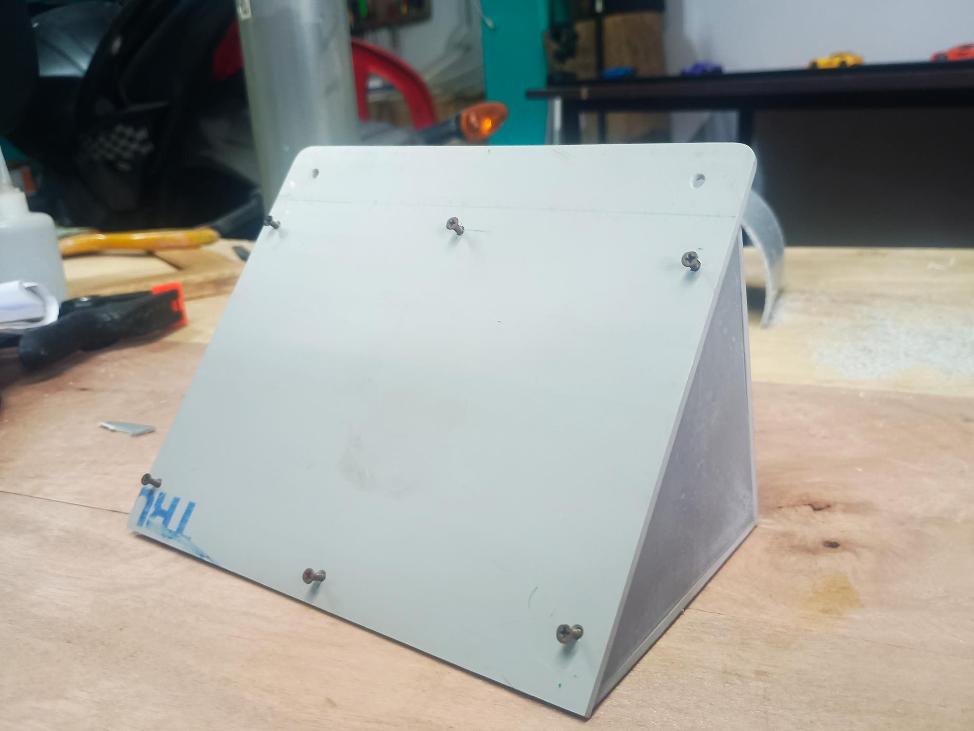
With all individual modules mounted—the parallel solar array, COB LED heatsink assembly, 18650 Li-ion battery, solar charge controller, and TTP223 touch switch—it is time to complete the final system interconnects, run diagnostic tests, and seal up the rear cover.
- Charge Controller Connections:
- Solar Input: Connect the main solar bus line to the SOLAR port on the controller board.
- Battery Connection: Wire the 18650 battery holder leads into the BAT port.
- LED Output: Connect the COB LED wires through your dusk-to-dawn auto switch into the SYS OUT / LOAD port.
- TTP223 touch switch Connections:
- Power Input (VCC & GND): Solder power supply wires to the module's VCC (2.5V−5.5V) and GND pads, sourcing power from the solar charger system output.
- Signal / Output (I/O): Run the output wire from the sensor's I/O pin to trigger your LED driver/auto switch circuit.
- TTP223 Jumper Configuration: Configure the solder jumpers on the TTP223 board if needed (e.g., bridging jumper B to set the module to "Toggle/Latching" mode so one tap turns the light ON and the next tap turns it OFF).
- Final Integration & Testing:
- Insert 18650 Battery: Snap your 3.7V 2000mAh Li-ion battery into the holder.
- Insulation: Cover all solder joints and fine wire leads with heat-shrink tubing and glue to prevent short circuits against internal components.
- Capacitive Test: Tap the outside of the PVC side wall directly over where the sensor is glued inside. The LED should instantly toggle on and off right through the plastic casing!
Final Backyard Solar Wedge Light
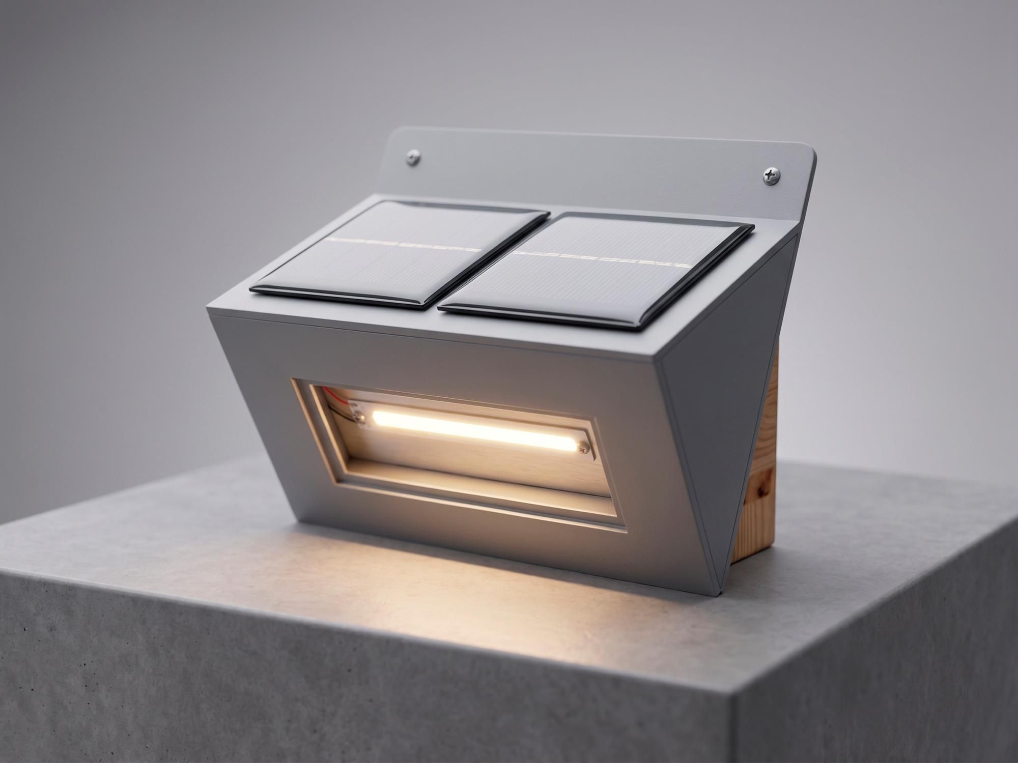
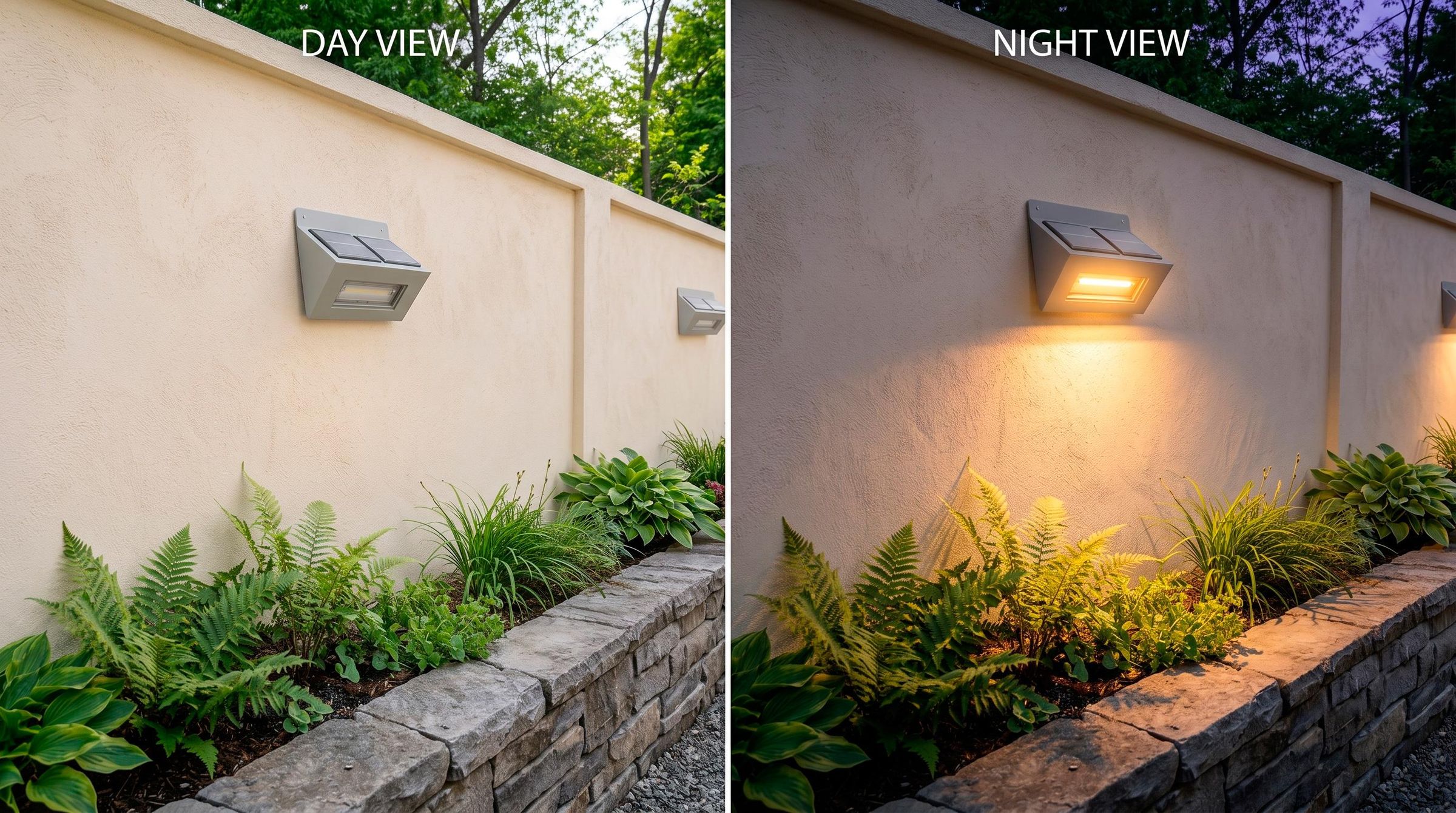
This DIY Solar Wedge Light is a compact, off-grid outdoor lighting solution built from heat-flattened PVC. It features a top-mounted parallel solar array, an internal 18650 Li-ion battery with charge control, a high-efficiency COB LED on an aluminum heatsink, and a completely concealed TTP223 capacitive touch switch for seamless, weatherproof control.
Here you transform a basic utility material into a sleek, weather-resistant enclosure that looks right at home along any backyard wall or garden fence. Whether you build just one to light up a dark doorway or assemble a series to illuminate an entire perimeter, this project proves that handcrafted, off-grid lighting can easily rival commercial fixtures in both aesthetics and performance.
__
Thank you so much for following along with this step-by-step guide! If you have any questions about the wiring, PVC shaping, or component selection, feel free to drop a comment down below—I’d love to hear your thoughts or see your own version of this project.
If you found this Instructable helpful, please hit the Favorite button and Follow my page for more DIY woodworking, electronics, and upcycling projects! Happy making!