Modular Climate-Resilient Housing for Drought-Prone Regions
by tejasthetj in Design > Architecture
1511 Views, 19 Favorites, 0 Comments
Modular Climate-Resilient Housing for Drought-Prone Regions


Hey there! My name is Tejas and I am a rising freshman at Cox Mill in Concord, North Carolina. I have a strong passion for engineering and 3D printing, and I love participating in competitions like this to showcase my talents. The idea for this project started taking shape during new years, when I began thinking more seriously about the growing housing and climate challenges in Arizona. I had been reading about the ongoing droughts and rising temperatures, and I wanted to create something that could actually respond to those problems. That’s when I came up with the concept for a modular home system, affordable, expandable, and designed to survive harsh, dry conditions. Over the past few months, I’ve worked on designing structures that collect their own water, power themselves off-grid, and stay cool without relying on traditional air conditioning. Overall this project has taken me around 5 months and I am proud to share it with you!
Table of Contents:
Information stage:
Step 1: The Inspiration
Step 2: The Problem
Step 3: The Solution
Step 4: Design Requirements
Step 5: Proposed Solutions
Brainstorming:
Step 6: Drawing
Step 7: Dimensions
Step 8: Rainwater Harvesting
Instructions for CAD:
Step 9: Right Module
Step 10: Right Module Roof
Step 11: Left Module
Step 12: Left Module Roof
Step 13: Middle Module
Step 14: Middle Module Roof
Step 15: Attachable Module Right
Step 16: Attachable Module Left
Step 17: Modifications To Roof For Attachable Modules
Step 18: Assembling The House
Analysis:
Step 19: Overall Design
Step 20: Greywater Recycling System
Step 21: Expansion
Step 22: Potential Problems
Step 23: Floorplan
Step 24: Costs
Bringing the house to Life:
Step 25: Printing it
Step 26: Getting ready
Step 27: Putting On Windows
Step 28: Left Module Assembly
Step 29: Right Module Assembly
Step 30: Center Module Assembly
Step 31: Assembling The Whole House
Step 32: Testing The Model
Conclusion:
Step 33: Acknowledgements
Step 34: Reflection
Supplies
Software:
- Autodesk Fusion for Design(Student license available)
- Bambu Studio for 3D printing - Completely free to download
- Homestyler (interior floorplan and room renderings)
- Video Editor (for walkthroughs)
Materials:
- Paper and pens for sketching
- Colored pencils
- 1/2 kg of black and white PLA filament for 3D printing
- Acetate Sheets (for realistic window glazing)
- Krazy All-Purpose Glue
Tools:
- 3D Printer
- Safety Gloves
- Eye Protection
- Ruler or Straight Edge
- Sandpaper (for smoothing connection points)
- Scissors (for cutting acetate sheets)
- Small Pliers (for removing supports)
- Ziploc Bags (for simulated rainwater testing)
- Bowls (to collect and measure rainwater)
The Inspiration
A few months ago while scanning the news, I kept reading stories about the extreme heat in Arizona. At first, I gave little thought to it till I came across footage of dry lakes, water trucks in communities, and people spending a fortune just to maintain their homes habitable. It started to hit me how bad things were becoming.
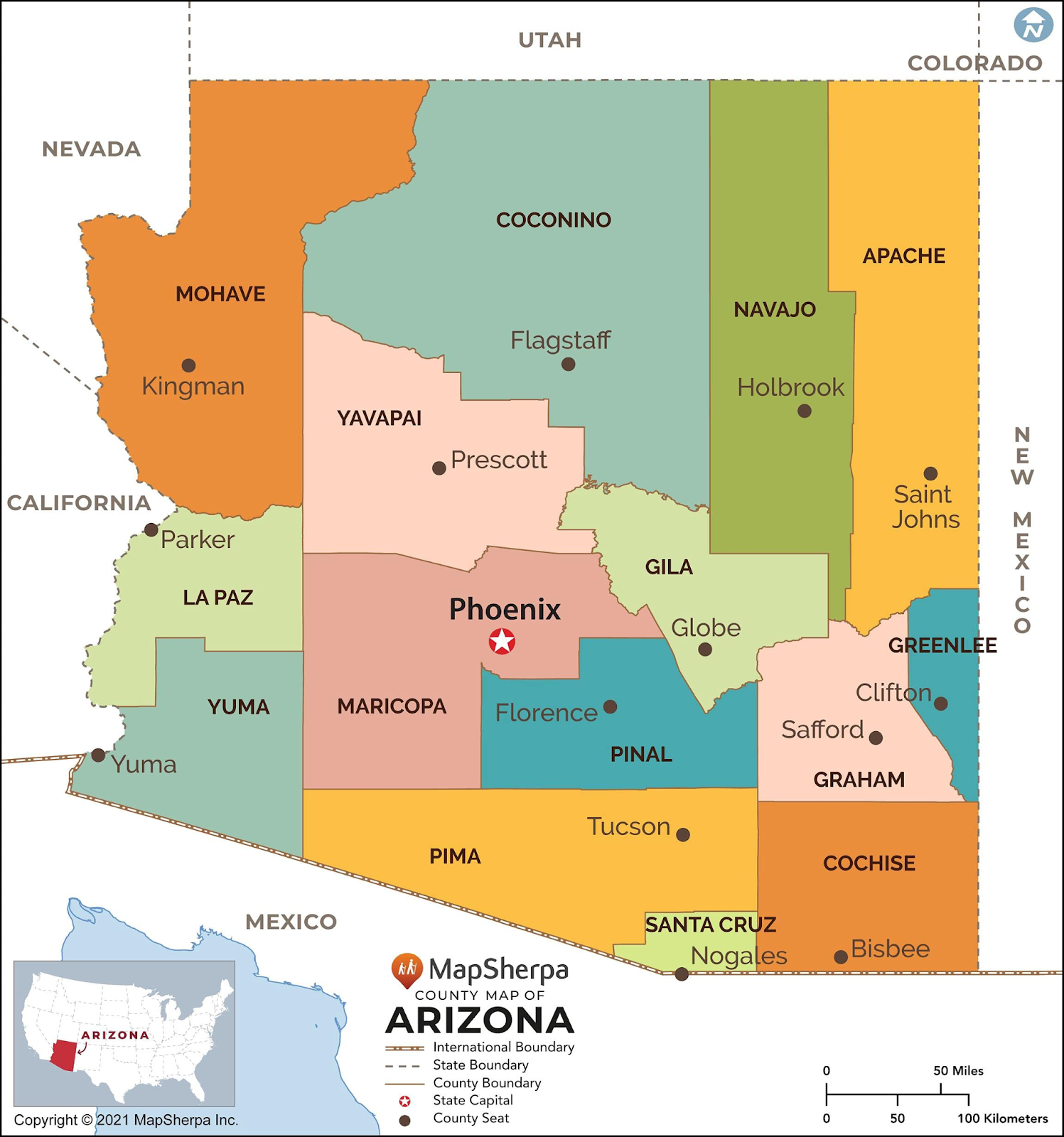
I began investigating it more and discovered it was a full-on housing and water catastrophe rather than only a heat issue. People are having trouble finding homes to buy at the same time that cities like Phoenix and Tucson are running low on water. Water restrictions are making new houses more difficult to construct, and a lot of families simply lack viable alternatives.
That's when I began to wonder: what if I could create a home that really co-operates with the surroundings rather than battles against it? Something that doesn't cost a lot to construct, stays cool, and conserves water. That concept stayed with me and sparked this entire journey.
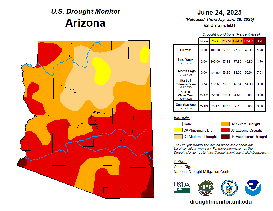
The Problem
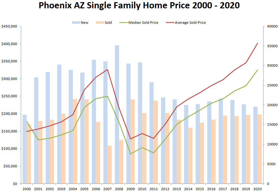
Phoenix, Arizona is now experiencing one of its worst and longest droughts in recent times. Almost the whole state suffered drought conditions between 2022 and 2023, with some areas getting less than half of their usual rainfall. Strict water conservation techniques have had to be put in place in places such Phoenix and Tucson for the long-term depletion of essential water supplies including underground aquifers and the Colorado River.
Drought changes everything, including our building approaches; it is not only about water. Traditional construction methods depend on water-intensive concrete curing, parched landscaping, and energy-hungry cooling systems that fail under high desert heat. Phoenix's population is meanwhile increasing fast, which raises property values and adds more stress to an already tight housing supply.
Low income families are hit hardest. Many are being priced out of even basic housing as rents, water bills, and power expenses soar. Along with being inexpensive and simple to construct, they need to be sustainable in drought situations, employing less water, energy, and can change along with the climate. Therefore, we must build a cost, energy, and resource efficient home for everyone to use.
The Solution
After some research on building techniques, modular building techniques and 3D printed housing stood out.
Using 3d printing technology, 3D printed homes are created from layered concrete to print walls and structures straight off site. With less labor and waste, these houses can be made in under 24 hours.
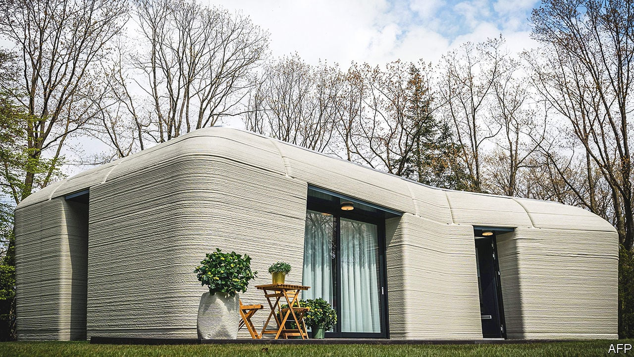
The organic shapes made available by this method are seen clearly in this photo.
More significantly, these residences depend on wood framing, therefore saving trees as well as lowering fire risk. Another rising risk in drought-hit zones.
Though concrete is a very good material for 3d printing homes, it has some drawbacks. First off, concrete is not a strong insulator and would have to be mixed with something else to be effective enough for the phoenix weather. Second, a major contributor to carbon emissions, which is at an all-time high, is Concrete.
Following some investigation, geopolymer paste seems to be an excellent substitute. Though about 50% more expensive, this paste is just as strong, if not more so, as concrete and serves as a much better insulator than some of the conventional methods of insulation. It nearly entirely natural, thus it removes all the drawbacks related to global warming on top of everything else. It is a perfect material for 3d printing since it has no necessity for additional insulation and is also less expensive than concrete since it offers more defense against natural disasters (can withstand winds form a category 4+ hurricane)
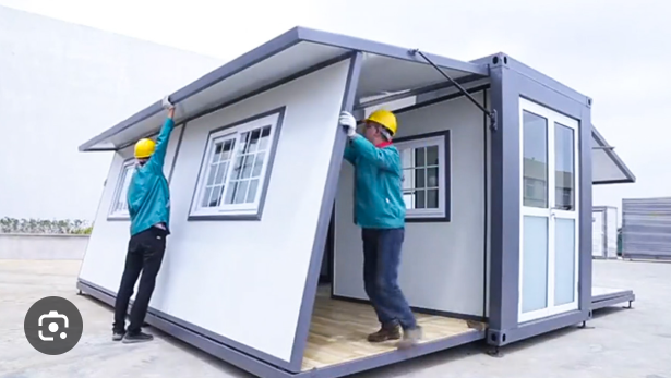
To match this, I turned to modular construction. This method lets homes be prebuilt in segments at a plant before being delivered and constructed onsite. Particularly in places with insufficient access to construction supplies and water, it is ideal for quickly constructing cheap housing.
Designing a new form of housing for a new kind of reality in Phoenix rather than simply surviving drought is the aim of this solution. Smart technology, sturdy construction, and a water efficient strategy enable us to create future-ready homes that are also inexpensive.
Design Requirements
Requirement #1: The region faces a long term drought emergency and extreme heat.
I found that Phoenix, Arizona has been under long-term drought stress for over a decade. Many areas live under permanent or near-permanent water restrictions. So any home built here needs to use as little water as possible and deal with extreme heat. That means using materials that reflect heat, and relying on passive cooling rather than energy draining AC units.
Requirement #2: Independent housing

During my research, I noticed power grids are becoming more unstable, especially during summer surges. Water systems are also failing more often. Homes need to be self-reliant , using solar panels, battery storage, and off-grid water systems, to stay functional even when utilities fail.
Requirement #3: Adaptable to climate migration patterns.
As climate conditions worsen in some areas of Arizona, populations are shifting, often from rural drought stricken regions to urban centers or more water secure zones. To remain relevant and cost effective, affordable housing must be easily relocatable. This means units should be easy to transport and reassemble in different locations, according to demand.
Proposed Solutions
Requirement #1: Long-Term Drought Emergency and Extreme Heat

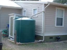
Solution 1: Butterfly Roof + Rainwater Harvesting System
Why: In drought-prone areas, capturing even small amounts of rain is crucial. A butterfly roof is designed to make the most of rare rain events.
How: Instead of sloping outward like a traditional roof, the butterfly roof slopes inward, directing all rainwater into a central gutter. From there, water is funneled into storage tanks, filtered, and used for irrigation or non-potable indoor needs like toilet flushing. This reduces reliance on city water, conserves a limited resource, and helps manage stormwater more effectively.
Solution 2: Graywater Recycling System
Why: In homes, a lot of water is wasted after single use, especially from showers, sinks, and laundry. Graywater systems give this water a second usage.
How: Used water from household sources is diverted into a separate filtration system, cleaned through multiple stages, and stored for reuse. It can be used to flush toilets or irrigate landscaping, reducing the need for clean water and lowering monthly water bills.
Solution 3: Cooling techniques
Why: The Phoenix heat can get really bad and having your AC do all the work is extremely inefficient. This is why we need to implement cooling techniques
How: using reflective paint, materials with high R value, as well as the thermal mass properties of geopolymer paste, we can reduce the strain on cooling processes like the AC etc.
Requirement #2: Independent Housing
Design Solution: Solar PV + Battery Backup
Why: Phoenix faces frequent grid failures during heatwaves. Homes need reliable, off-grid power to remain livable.
How: Solar panels installed on the roof generate electricity during the day. Any extra energy is stored in a battery system, which powers the home at night or during outages. This setup reduces reliance on unstable grid infrastructure, lowers electric bills, and ensures that key systems like cooling, refrigeration, and internet stay on during emergencies.
Requirement #3: Adaptable to Climate Migration Patterns
Modular + Prefabricated Construction
Why: As people relocate due to drought and heat, housing must move too. Traditional homes can’t adapt, modular ones can.
How: Homes are built in standardized sections off-site and assembled quickly on location. If needed, they can be disassembled and transported to a new region. This flexibility makes it possible to respond quickly to shifting populations and changing environmental conditions.
Lightweight + Durable Materials (Geopolymer Paste)
Why: To relocate homes easily, materials must be strong but not heavy. They also need to stand up to heat, wind, and time.
How: Geopolymer paste is a sustainable, natural alternative to concrete. It insulates better, is fire- and water-resistant, and can be used for 3D printing. It’s strong enough to withstand hurricanes but light enough to make transportation practical, ideal for climate-adaptive housing.
Drawing
When first starting this project I felt stumped. I had no idea where to even start. That was when I just sat down, got my pencil and paper and started drawing. Once I found something that I sort of liked, I stuck with it.
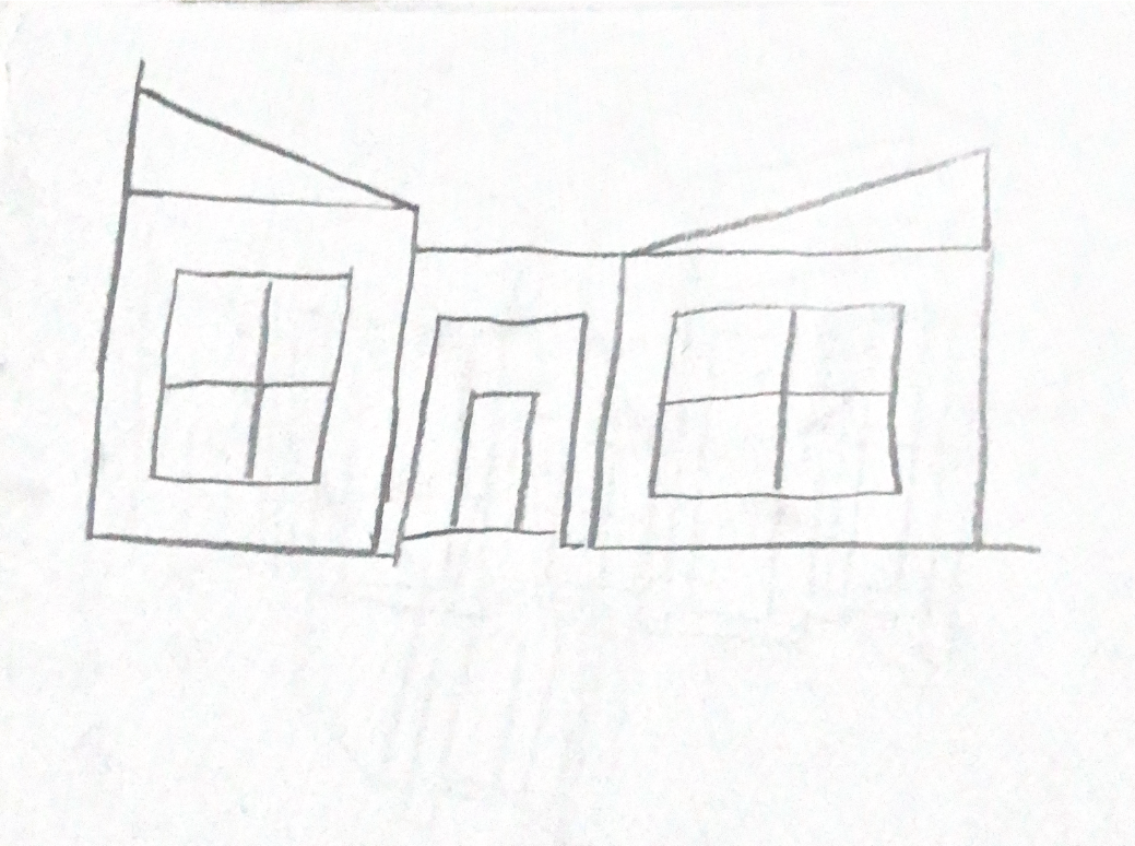
The first thing that went through my mind was a funnel for the roof. However that obviously wouldn't be too practical for a house. So I went with the next best thing, ramps. I liked this design, but felt it was way too simple and didn't have that much flair. So I went researching online for some inspiration and one thing that I saw in common with all the modern houses was the difference in depth. That was when I realized that this design was just way too flat.

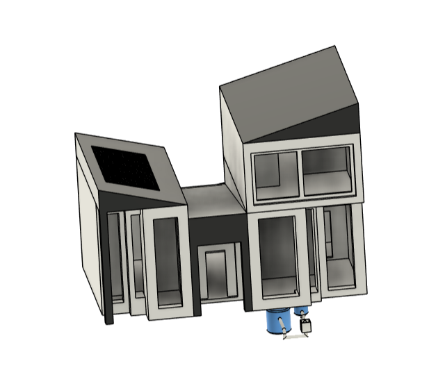
That was when I came to this design. This has a good blend of depth on the front and in the height, while also acting like a funnel toward the middle module roof. It also has 3 easily distinguishable modules for ease of construction and fabrication.

These are the 3 modules for the whole house. I named them the middle module, the left module and the right module as shown in the picture
Dimensions:
The most important part of a house, the amount of space. Taking into consideration the main goal of this competition is affordability, I made a house perfect for new families, partly because of the expandability. The family can order a house with 2 extra modules. Or if looking for a small home for a couple they can order it with 3 modules. So that was my plan, 2 people = 3 modules (including middle module) and 3+ people = 4+ modules (including middle module)
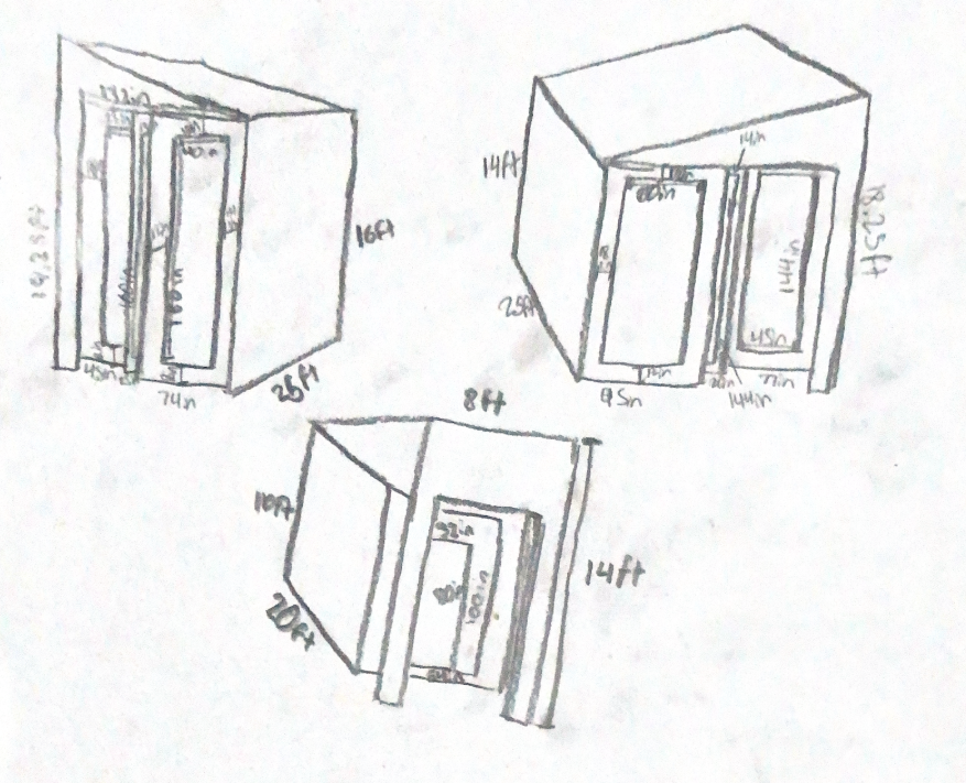
Unfortunately the picture got a little bit blurry but you can see the overall dimensions for every part of each module.
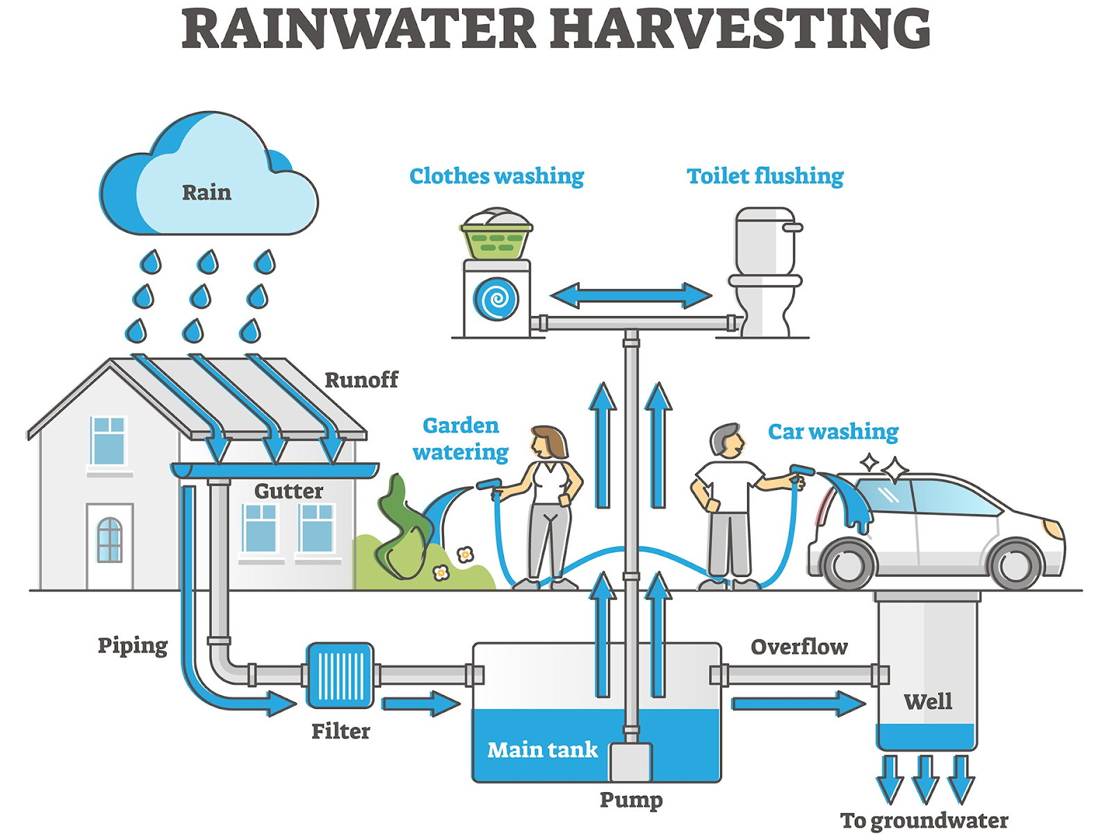
Rainwater Harvesting
Problem : One thing that kept coming up when talking to my peers about this design was the rainwater harvesting system. They were concerned that the system I had in place for storage of the rainwater would be very hazardous to the residents of the home because the water would remain unsterile and prone to bacterial infestations.

Solution: To address this concern, I integrated a carbon-based filtration system into the rainwater harvesting setup combined with a UV filtering system in the main tank. This system filters out bacteria, sediment, and chemical contaminants, making the collected water significantly safer for all uses. Additionally, because I placed the storage barrels underground, mosquito breeding band algae growth will not happen. This solution ensures that the rainwater remains clean, safe, and usable.
Right Module

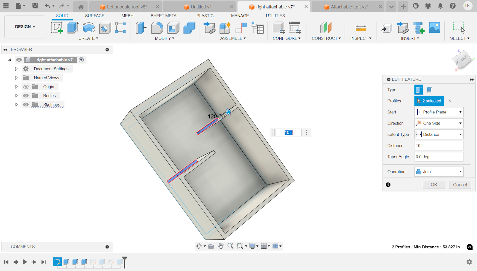
First make a sketch (2nd tool from the left), and select anywhere on the screen. This is called selecting a plane, and it shows where the sketch will be. For the right module we use the rectangle tool, highlighted in the top left, to make a big rectangle and then draw another one inside. Next use the dimension tool (shortcut d) to make the outer rectangle 300 in x 192 in. Then space out the inner rectangle 8 inches out from the outer rectangle and on one side, as seen in the left of the picture, make it 16 in wide. Next use the trim tool (T) and cut away the 16 in side and replace it with this shape. It extends 64 in and then goes to the right 16 and then extends another 20 in and goes right 16 in and then finally extends 77 in. Create lines parallel to this shape and space it out 16 from the original lines. You are now done with the walls.

In total, there is one wall that is 6 in wide and 52 in away from the bottom wall, spaced out 120 in from the leftmost wall. Next make a compartment as shown at the bottom right with 6 in walls and a 90 in long wall for the top and for the left side an 88 in wall.
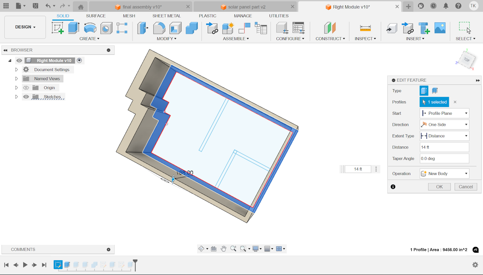
Using the extrude tool (6th tool from the left), select the outer edge of the rectangle and in the distance box type 14 ft. Make sure the operation is set to new body.

Using the extrude tool (6th tool from the left), select the floor of the module and in the distance box type 6 in. For the Operation, click join.
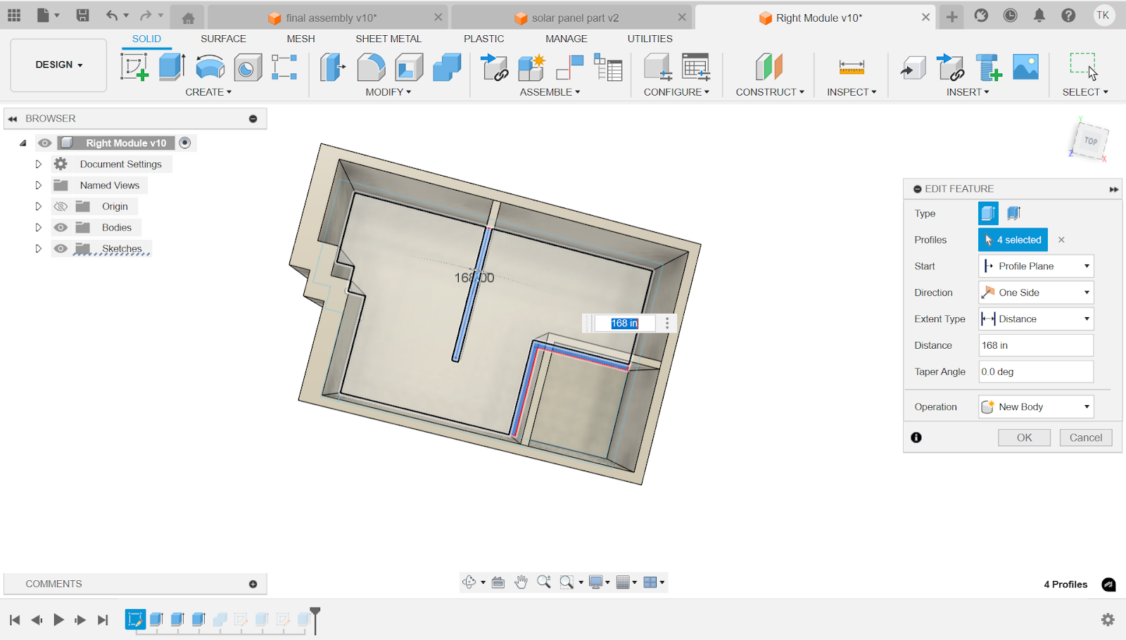
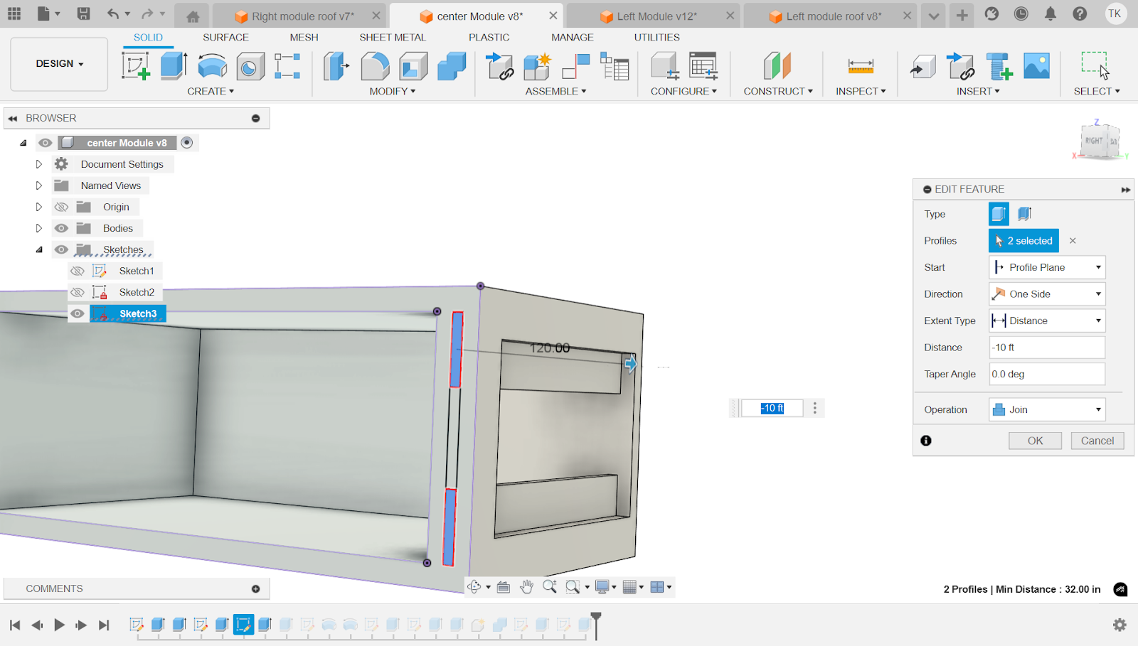
Now select the inner walls that we made in the floor plan and extend them to a distance of 168 in.

First make 3 Rectangles on the 3 corresponding faces. The first rectangle shown is 60 in x 144 in. Next on the 2nd face, the rectangle is 14 in x 144 in. Finally, the third rectangle is 45 in x 144 in. For now don't worry about the spacing.
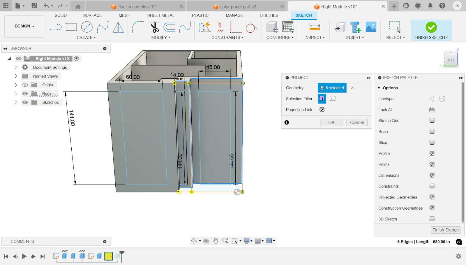
Now use the project tool (shortcut p) to click on the edges of the right most face as well as the 2nd face. This is to eventually space out the rectangles because the current sketch is not on the same plane as the faces. This feature allows you to have reference lines that are in your sketch for easy spacing.

Next copy this spacing in order to have your windows correctly placed on the faces.
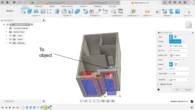
Now select the extrude tool and select the operation as cut. Now as extent type, put to object, and select the face on the inside of the module that’s farthest away from the sketch plane.
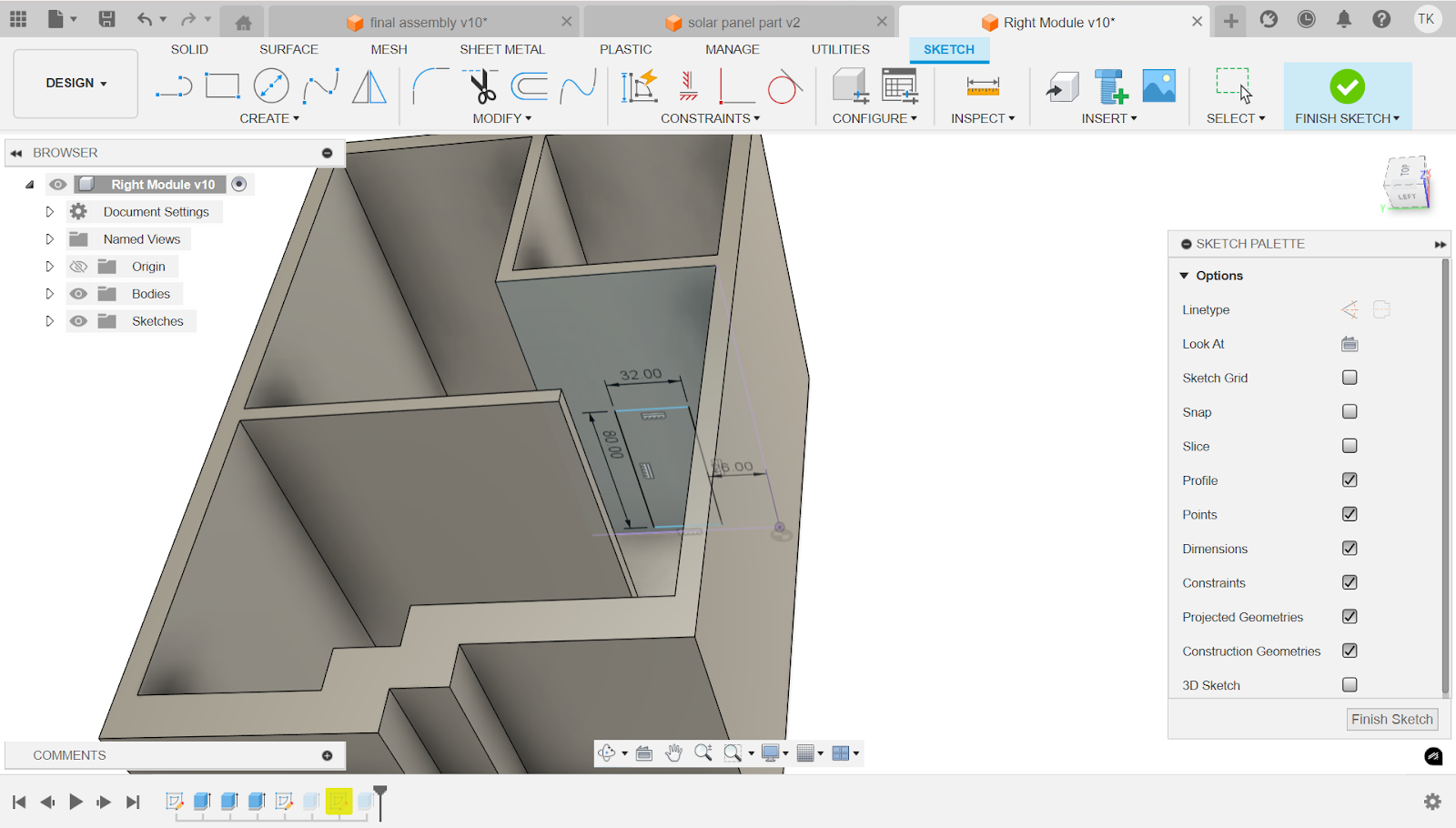
The next step is to create a door for this room. In order to do that we use the rectangle tool and the dimension tool (d) to make a 32 in x 80 in rectangle 26 in away from where the face that the doors on meets the module wall.

Now we use the extrude tool and set the operation to cut. We set distance to -6 in, so that we can cut the opposite way. Now you're done with your first module!
Right Module Roof

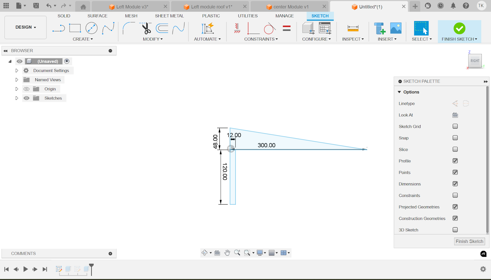
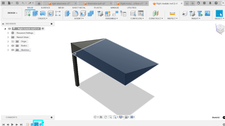
Make a triangle with the base at 192 in and the height at 51 in using the dimension tool. Next, also using the dimension tool (d), select the base and the height and select 90 degrees. This ensures its a right triangle

Now using the same extrude tool, we extrude the sketch to 300 in.

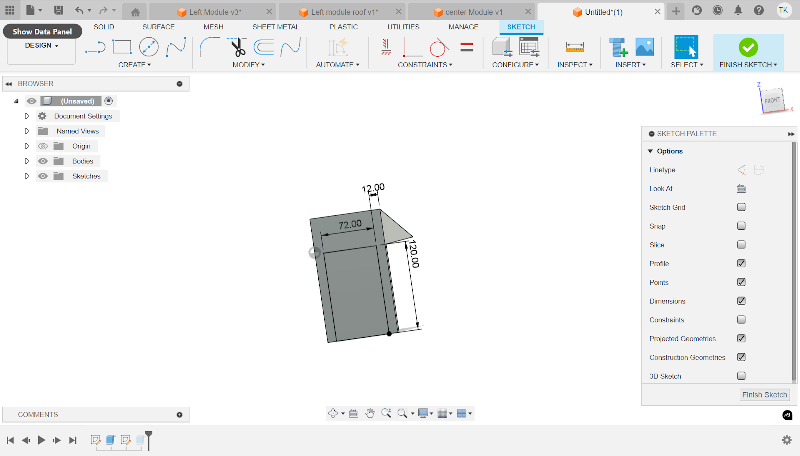
For the next step we go to the bottom face of the triangle and with the thin part facing away from you, make a 12 in x 12 in rectangle on the bottom right of the face.

Finally extrude the rectangle 14 ft away from the face. Make sure the operation is join so that it doesn’t create another body.
Left Module:

First make a sketch (2nd tool from the left), and select anywhere on the screen. For the left module we use the rectangle tool to make a big rectangle and then draw another one inside. Next use the dimension tool (shortcut d) to make the outer rectangle 300 in x 144 in. Next space out the inner rectangle 8 inches out from the outer rectangle and on one side, as seen in the right of the picture, make it 16 in wide. Next use the trim tool (T) and cut away the 16 in side and replace it with this shape. It extends 74 in and then goes to the left 32 and extends another 25 in and goes left 16 in and then finally extends 45 in. Create lines parallel to this shape and space it out as shown in the picture. You are now done with the walls.
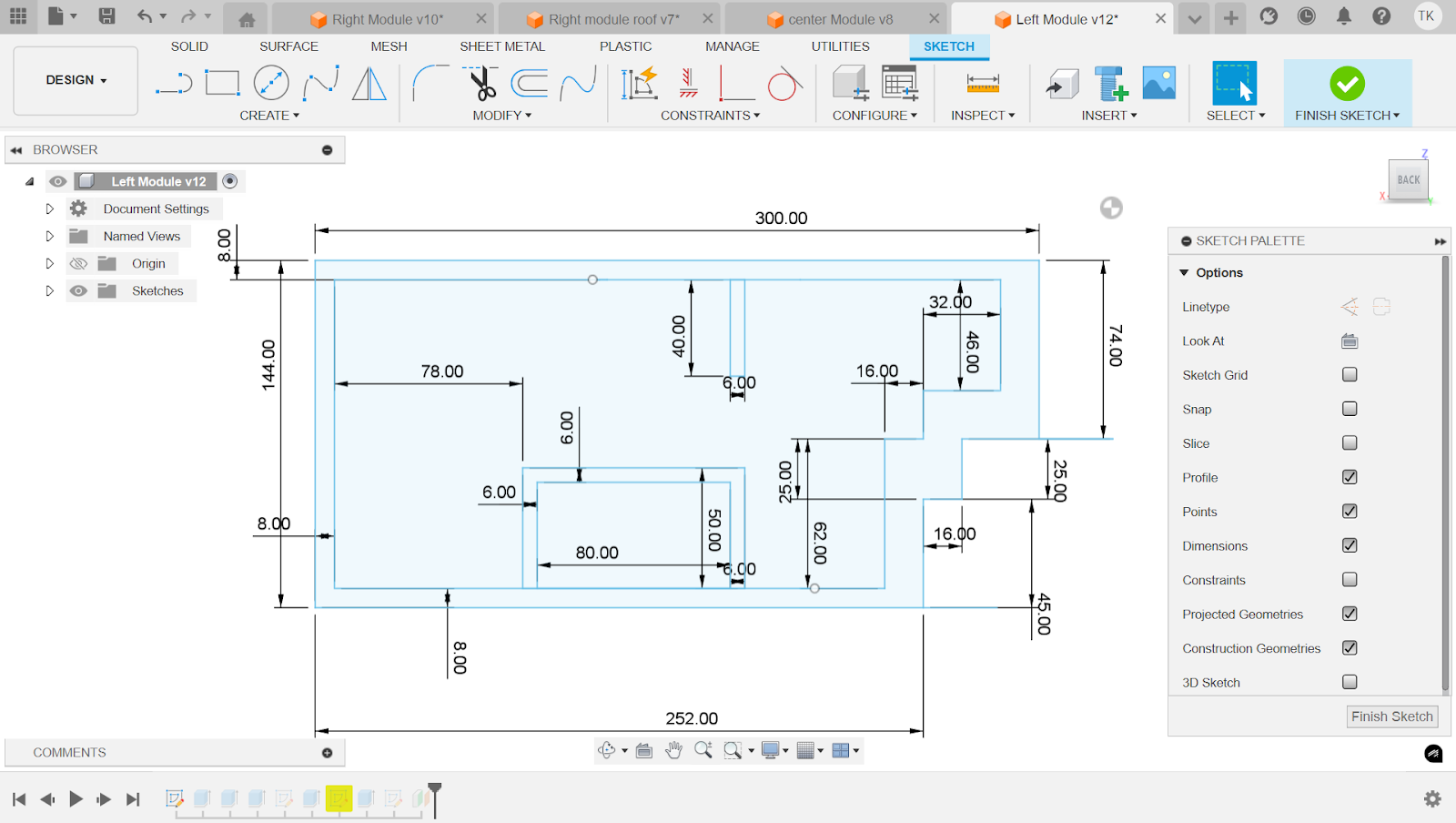
In total, there is one wall that is 6 in wide and 42 in long, spaced out 164 in from the leftmost wall. It should be in line with the room on the bottom. Next make a compartment as shown at the bottom right with 6 in walls and a 90 in long wall for the top and for the left/right side a 50 in wall.

Using the extrude tool (6th tool from the left), select the outer edge of the rectangle and in the distance box type 16 ft. Make sure the operation is set to new body.

Now using the same extrude tool, select everything inside of the outer walls. Set the operation to join and distance to 6 inches in order to make the walls.

Same exact process with the extrude tool, but for the walls on the inside, type 16 ft in the distance box and make sure the operation is join.
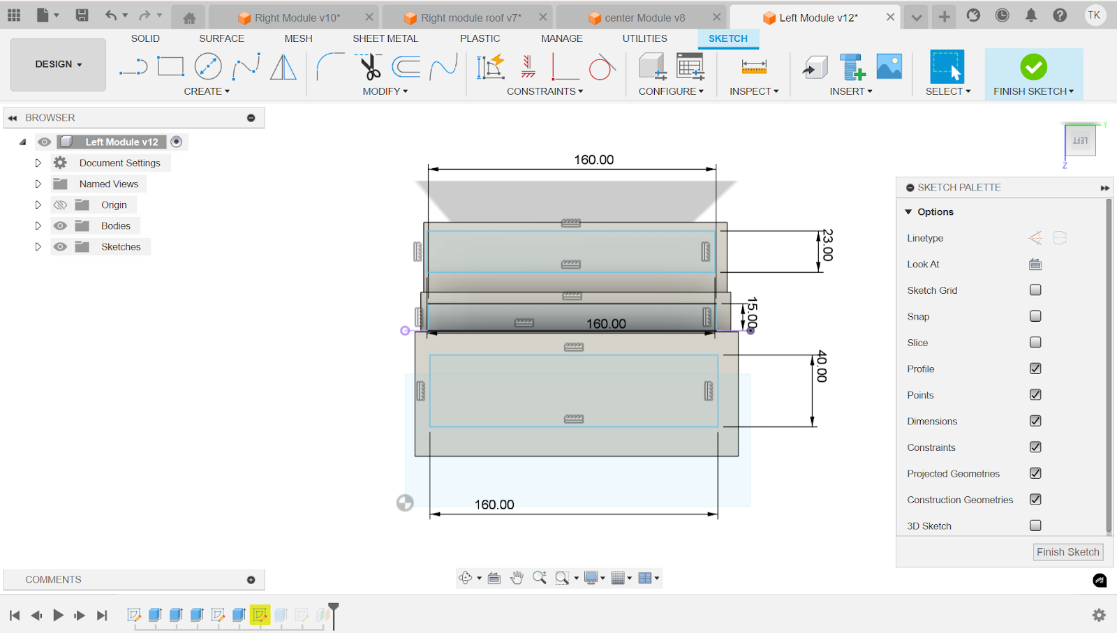
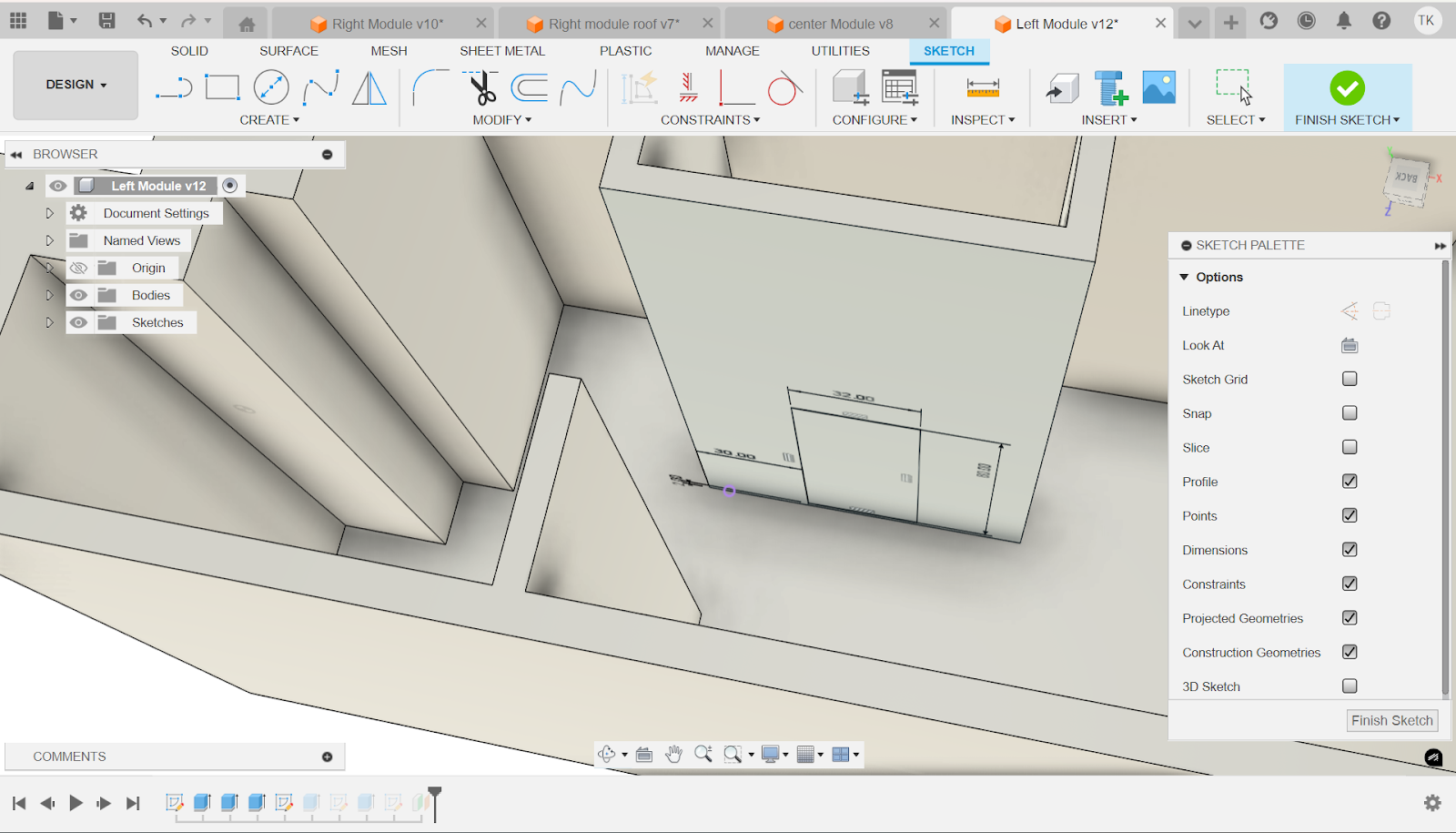
First make 3 Rectangles on the 3 corresponding faces. The first rectangle shown is 40 in x 160 in. Next on the 2nd face, the rectangle is 15 in x 160 in. Finally, the third rectangle is 23 in x 160 in. For now don't worry about the spacing.
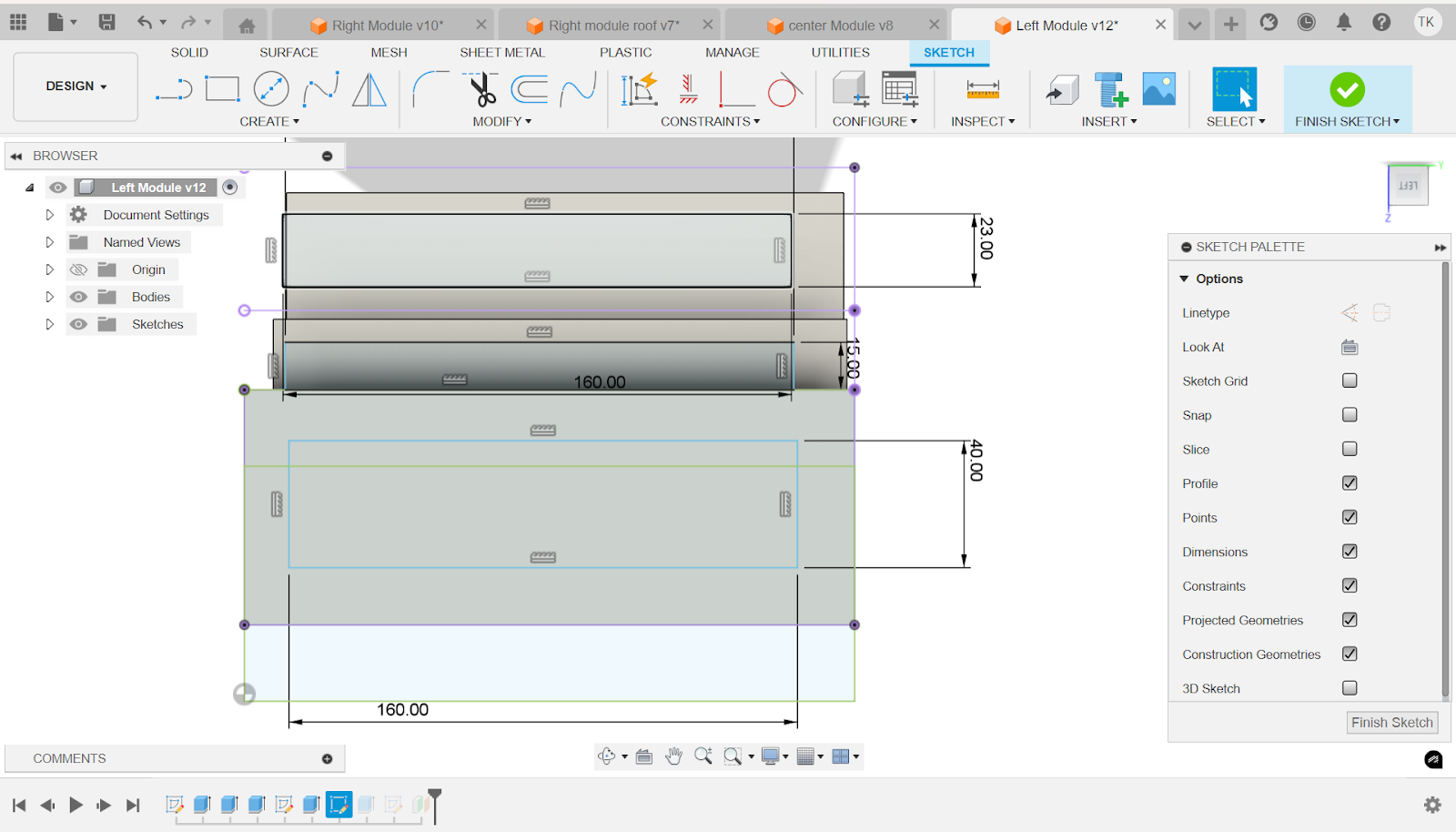
Now use the project tool (shortcut p) to click on the edges of the right most face as well as the 2nd face. This is to eventually space out the rectangles because the current sketch is not on the same plane as the faces. This feature allows you to have reference lines that are in your sketch for easy spacing.

Now copy this spacing easily using the dimension tool and your reference lines for the 1st and 3rd windows. For the second rectangle you have to add the 18 in spacing at the right but also you have to use the tool called coincident. You must click on the bottom edge of the second window and click on the reference line that is shown by the arrow. This will connect those 2 lines and make sure the window is properly spaced.
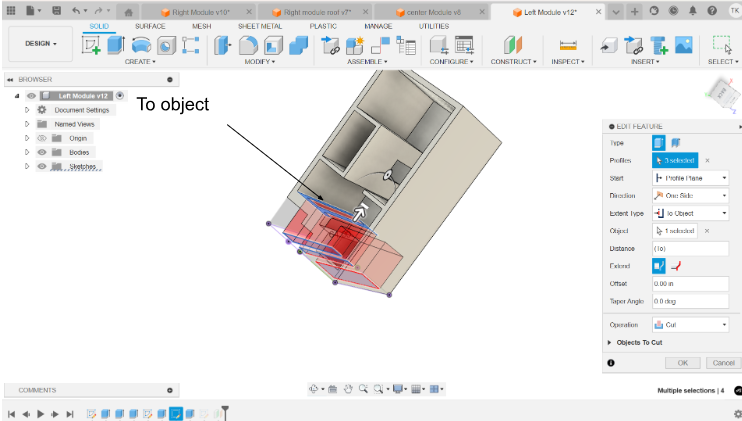
Now select the extrude tool and make operation cut. Now as extent type, put to object and select the face on the inside of the module that's farthest away from the sketch plane.
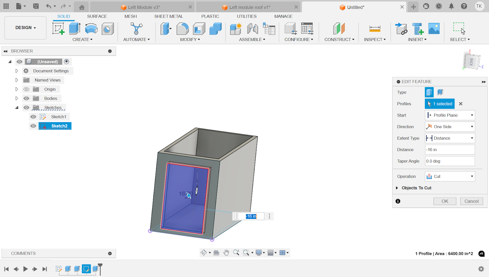
Now that we’re done with the windows, make a sketch on the face of the room. On that sketch draw a 32 in x 80 in rectangle spaced out 30 in from the left and 2 in from the floor.

Finally using the extrude tool use the operation cut and distance of -6 in because that's how thick the walls are.
Left Module Roof
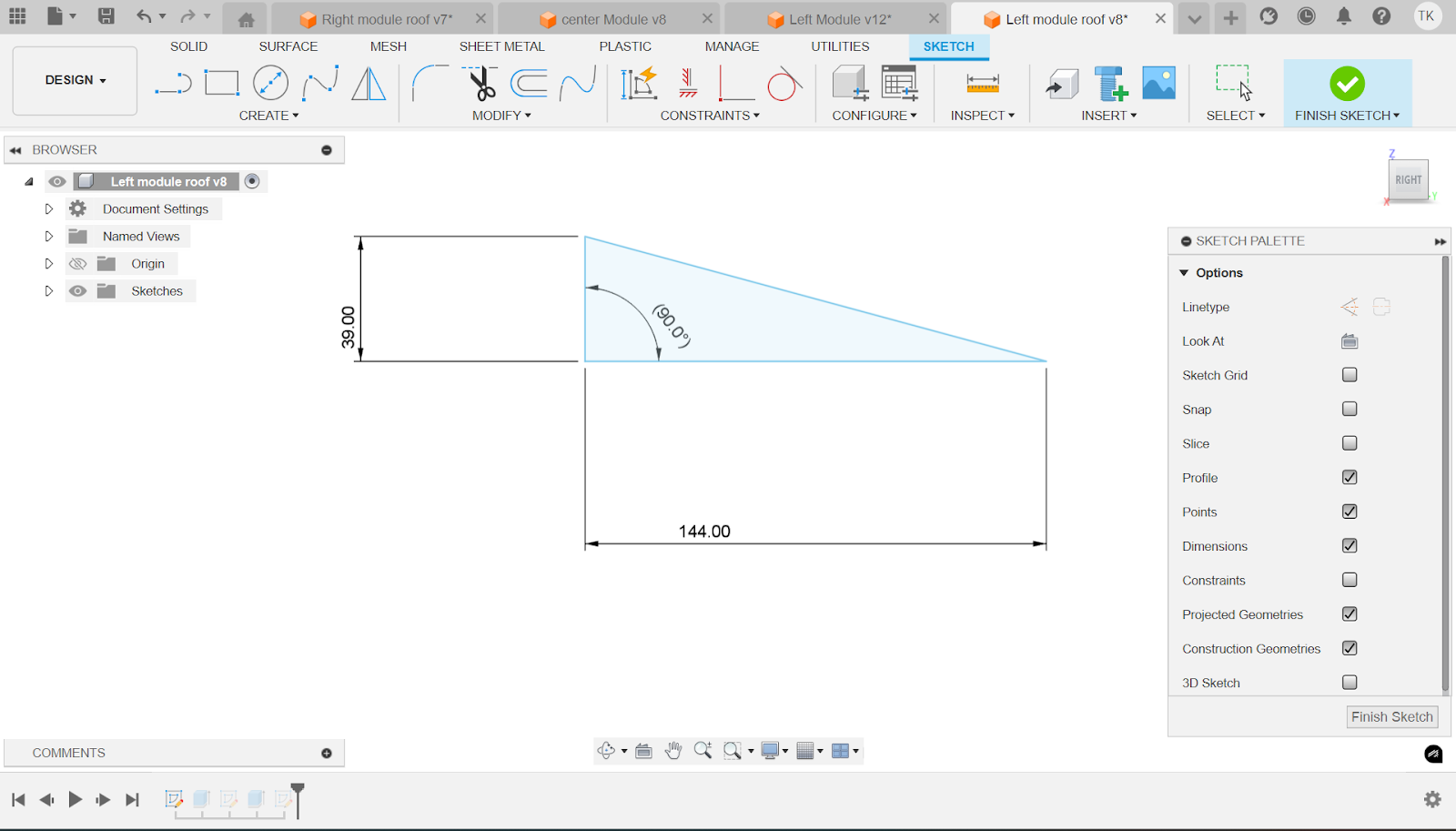
Make a triangle with a base pf 144 in and a height of 39 in using the dimension tool. Next also using the dimension tool (shortcut d) select the base and the height and select 90 degrees. This ensures its a right triangle

Next using the extrude tool, extrude the sketch to 300 in with the operation of new body.

Now with the thin side facing away from you, make a 12 in x 12 square on the bottom left of the face of the triangle.

Then using the extrude tool extrude the 12 in x 12 in to a distance of 192 in with the operation of join.
Middle Module

First make a rectangle that is 240 in x 96 in. Then make a smaller rectangle inside of the existing rectangle and space each side of the smaller rectangle 8 in away from the big rectangle. Next, make one side 16 in away from the outside rectangle.

Now use the extrude tool to extrude the outer edge of the sketch to 10 ft.

Next use the same extrude tool to extrude the floor to 6 in with the operation of join

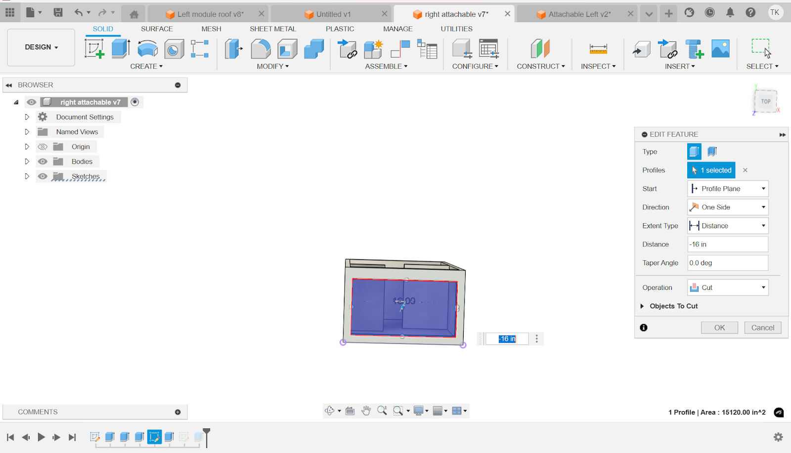
Now on the 16 in thick wall make a 64 in x 100 in rectangle that is spaced out 16 in from the edge at the top of the picture, and 6 in from the leftward edge.
Now using the same extrude tool, select the profile of the rectangle and set the distance to -16 in. Set the operation to cut.

At the top of the module, on the 16 in side create a 4 in x 80 in rectangle. Inside the rectangle put 2 lines, both 24 in away from their respective sides. Space out the big rectangle 6 in from the inside wall.
Now use the extrude tool to extrude the outer 2 rectangles to -10 ft as well as make the operation to join.

Now extrude the middle rectangle - 34 in with the operation join.
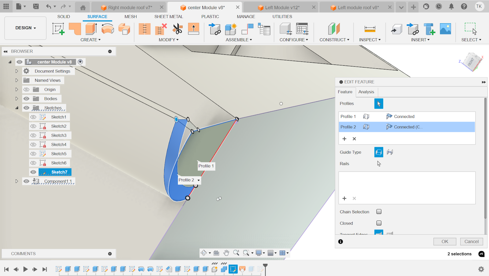
Now that the door is done we can focus on the rainwater harvesting system. The first step to that is the gutter. Make 2 lines go down from the top corners respectively, each one 43 in and then connect them using another line. Next, use the dimension tool to make that line 11 in. Do the same thing 2 more times. Spacing the 2nd and 1st paths by 5 in. This is to make the gutter 5 inches in diameter so that it will be efficient in harvesting the water. Next space the 2nd and 3rd path by 1 in. Next click on the constraints drop down and scroll down until you see parallel. Then click every line on the 1st path and click the corresponding line on the 2nd path. Do the same for the 2nd and 3rd path. Finally, using the dimension tool (d), click the first path and the top edge and set it to 10 degrees.
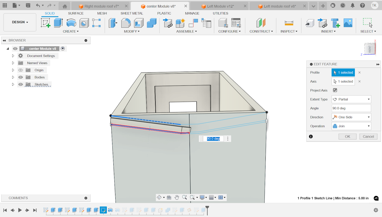
Next using the revolve feature click on the left half profile between the 2nd and 3rd path, and for the revolve axis, click on the left line of the first path.

Next using the revolve feature click on the right half profile between the 2nd and 3rd path, and for the revolve axis, click on the right line of the first path.
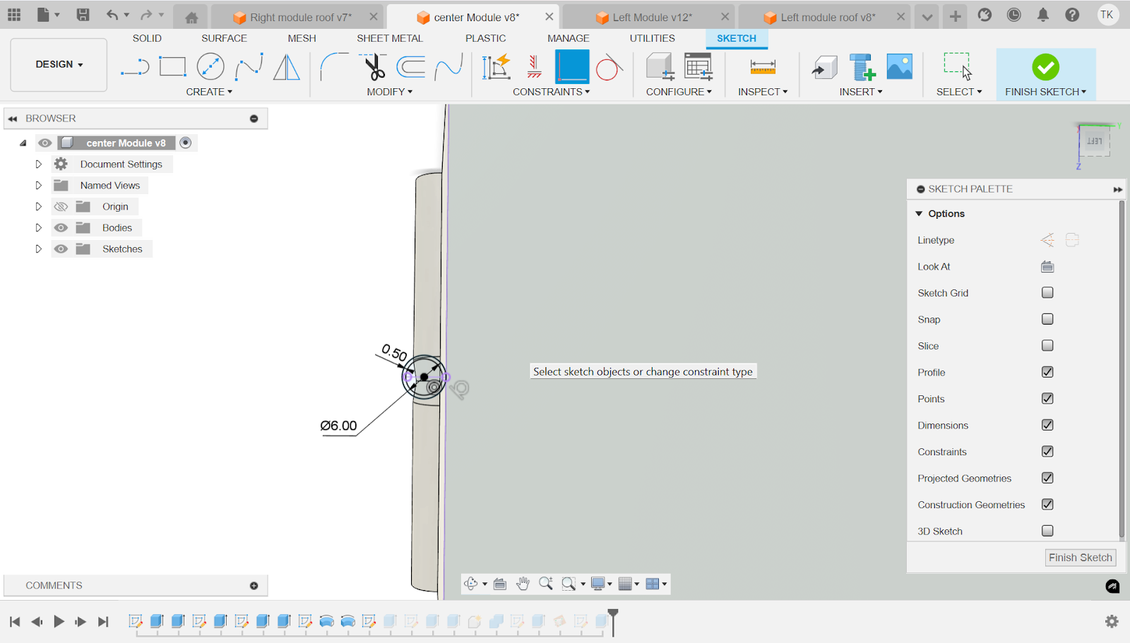
Now in order to make a connection point underground, make a new sketch and select the bottom of the module as the plane. Make a 6 in circle and another circle inside that one. Space out the inner circle and outer circle by 0.5 inches. Next click on the dropdown of constraints and scroll down until you see tangent. Click on the outer circle and the edge of the module.
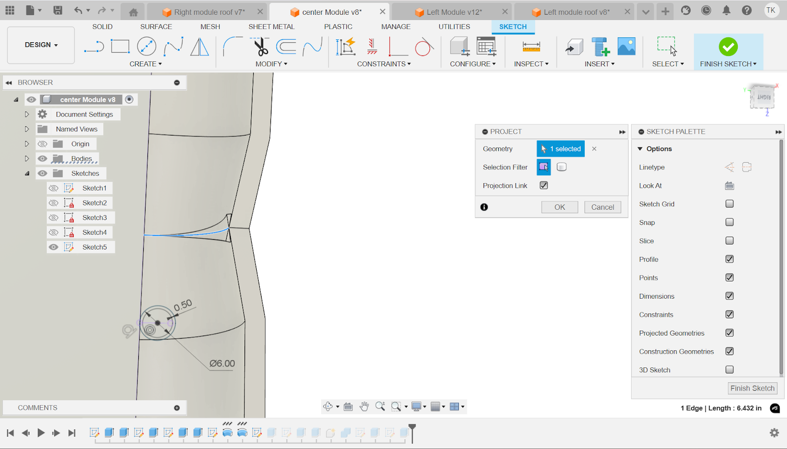
Now using the project tool (p) click on the middle line where the 2 downward sloping gutters meet.
Now using the project line as reference go to constraints and click coincident. Now click the center point of the circle and the projected line. This is so that the pipe is in the middle of the downward sloping gutters and properly spaced.
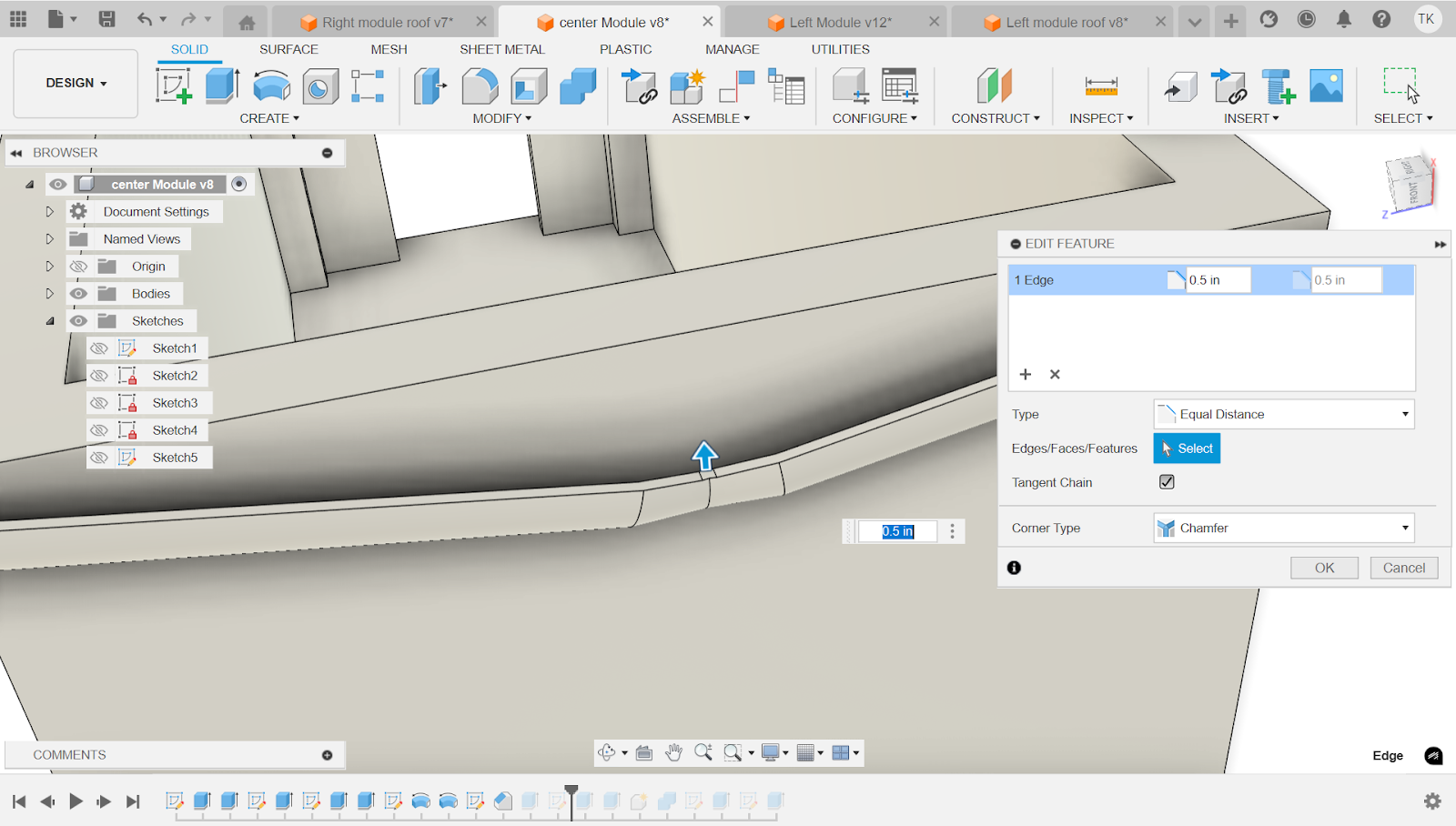
In order to have the pipe be the correct height we need a reference for the to object extrusion. In order to do that we will use the chamfer tool on the middle line where the 2 gutters meet and extend it 0.5 in. This will ensure a flat face for the pipe to extend to.
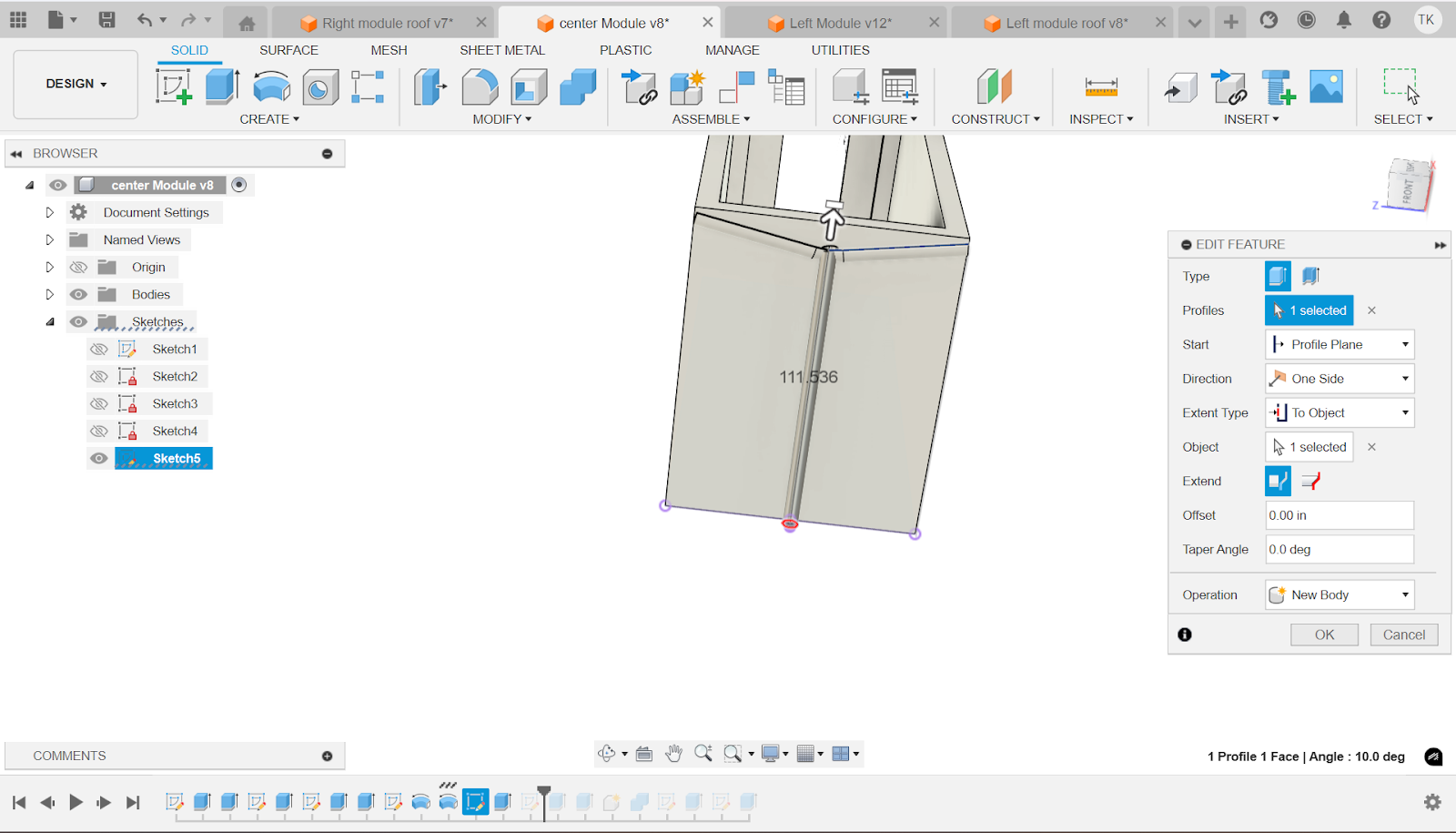
Now extrude the profile between the inner and outer circle. Select the extent type and scroll down until you see “to object”. Once you have done that, click on the selector right underneath (Object) and click on the face of the gutter that we made in the last step. This will make sure the pipe matches flush with the gutter.

When we do that extrusion a certain amount of pipe sticks out from the gutter. In order to combat this we must remove it manually. We use the project tool and select the line shown in the picture. Then on the sketch, we connect the arc endpoints and the center points.
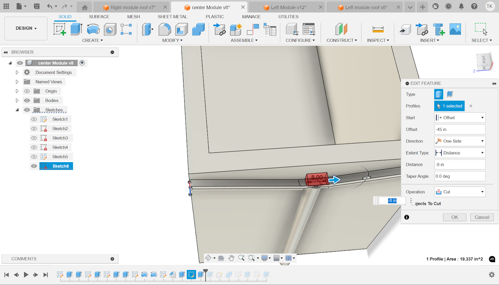
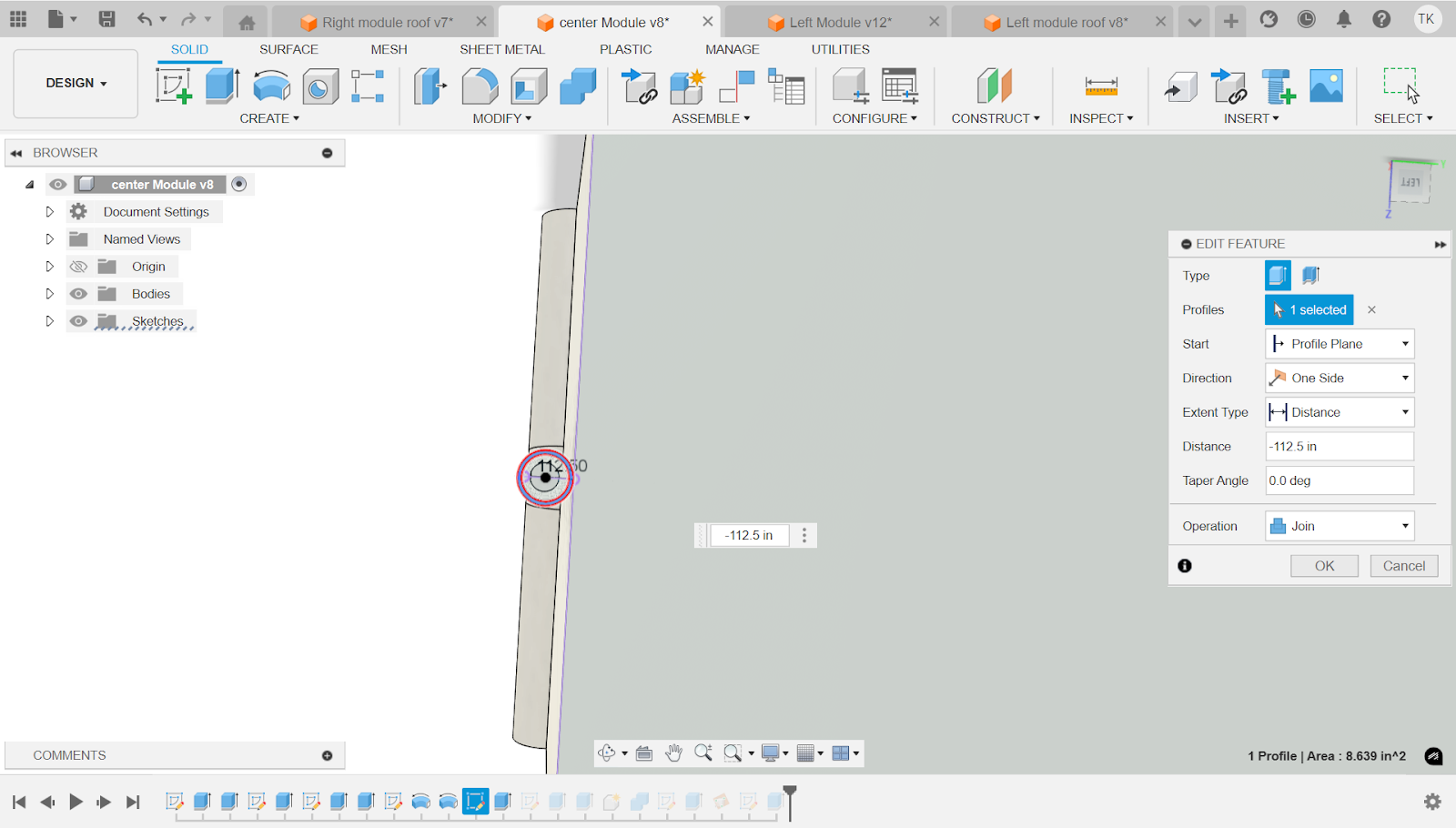
Now select the profile of the sketch you just made. Click on the start dropdown and select offset. Now in the offset box that just appeared put -45 in. This is to make the cut start at exactly where the pipe is, and avoid cutting parts of the gutter we don't want to.

Now using the extrude tool, select the inside of the circle. Then make the distance to 114 in. This will make sure there is no longer anything blocking the transfer from gutter to pipe.

Now using the combine tool (highlighted above), select the module as the target body and the pipe as the tool body.
One major problem with this is, if a large amount of water was to flow, the gutter would not be able to use gravity to its fullest because the water would just fall off the sides of the gutter. In order to fix this we must create sides for the gutter. In order to do this use the project tool to select the outer edge of the gutter. Then use 2 lines to connect the arc endpoints to the center point.
Now navigate to the top and select surfaces. Then click on the create drop down and select loft. Next select the edge of the gutter and the sketch that you just created. That will create material there that will allow the sketch to be coplanar now to the gutter.

Now use the extrude tool to extrude the sketch you made to -0.5 in. This is to make the actual side to the gutter.

Now do the exact same thing to the other side with the sketch.

Now loft it the same way.

And finally extrude it 0.5 in.

You're now done with the middle module! However you will notice that the sides of the gutter is a different color than the rest of the gutter. This is because the loft was made as a new body. This created multiple bodies. To combat this we must use the combine tool in order to make it one body.
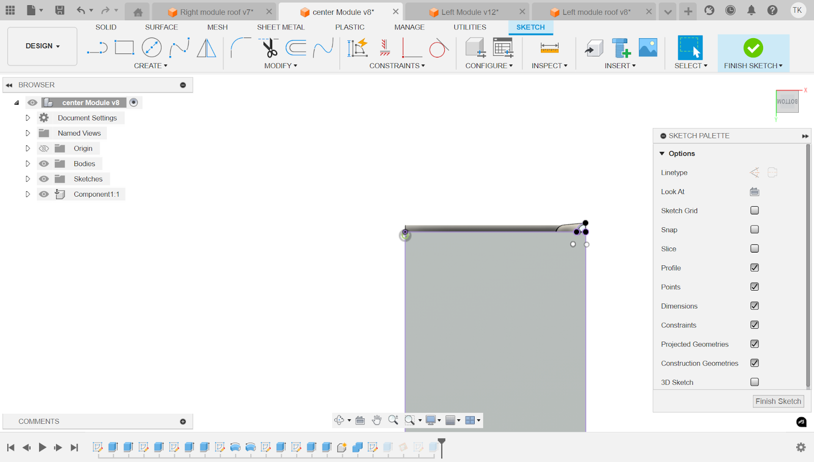
Middle Module Roof
First make a sketch. Then make a triangle with base 300 in and height 48 in. Next make a rectangle at the thick side of the triangle with thickness of 12 in. Next make the length of the rectangle 120 in.

Now extrude this sketch to the distance of 96 in.
Now go on to the side with the 12 in thick rectangle that we extruded in the first sketch. Now make another rectangle that is 72 in x 120 in and spaced out 12 in from the side. Make sure it is connected to the bottom as well. If needed, use coincident, like we used it before, to connect those 2 lines.

Finally extrude the sketch -12 in with the operation being cut.
Attachable Module Left

First, make a big rectangle 144 in x 300 in. then inside of that rectangle make a smaller one. Next using the dimension tool space out the inner rectangle 8 in from the 3 sides and for the rightmost side space it out 16 in. Now in the bottom left side of the rectangle make an 80 in x 80 in rectangle, and then inside of that rectangle make another one and space it out 6 in from the outer wall. Next make a small rectangle in the top middle of the inner wall. Make it 60 in away from the edge of the 80 x 80 in room. Make the length of said rectangle 50 in and the width 6 in.

Now use the extrude tool to extrude the outer edge of the module.
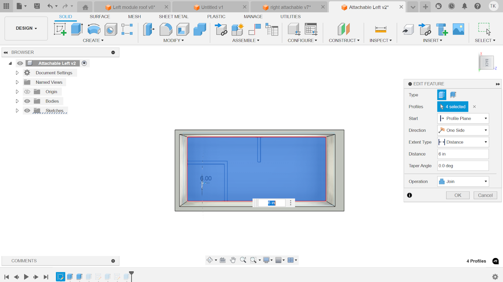
Using the same extrude tool, now select the floor of the module. Make sure the operation is join and then make distance 6 in.

Now extrude the room walls. Operation is join and the room height is 10 ft.

Make a new sketch at the thick side of the module and space a rectangle 12 inches from the left, bottom and right edges. On the top, space it out 18 in.

Now with the extrude tool select the extent type “to object” and select the other side of the 16 in wall so that the sketch extrudes to that extent. Make sure the operation is cut as well, but it automatically does that when you do “to object” and click the other side of the wall.

Now create another sketch on the same face and make a small rectangle and space it out 6 in from each edge. Next make an 8 in rectangle in the middle. Space it out 50 in from the side of the inner rectangle. Finally use the trim tool (shortcut T) to cut away the unnecessary lines.
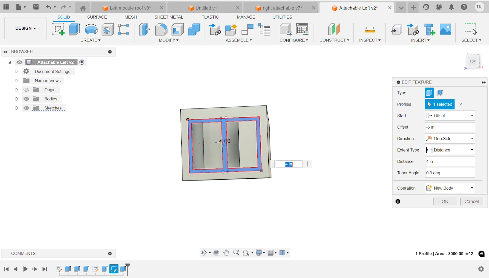
Now use the extrude tool to select the sketch that we just made. Select the start as offset and set the offset to -6in. Then set the distance to 4 in.
Attachable Module Right
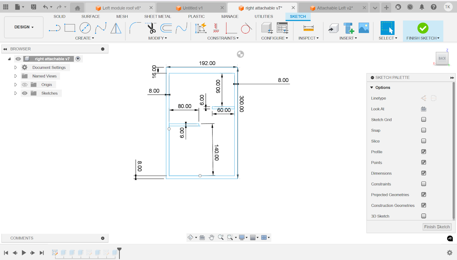
For the first step make a big rectangle 192 in x 300 in. then inside of that rectangle make a smaller one. Next using the dimension tool space out the inner rectangle 8 in from the 3 sides and for the rightmost side space it out 16 in. now make one rectangle 6 in x 60 in and connect it to the right wall. Space it out 90 in from the top wall. Now make another rectangle 6 in x 80 in and space it out 140 in from the bottom wall (if spacing from the top side of the 6 in x 80 in rectangle).
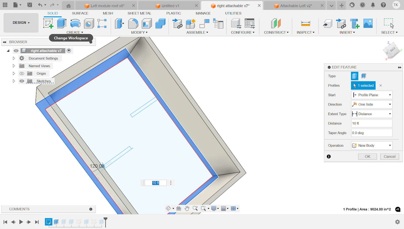
Now using the extrude tool, extrude the outer edge to 10 ft.

Now extrude the floor to 6 in
Finally the walls

Now on the 16 in side of the wall make a new sketch. Make a rectangle on that face and space it 12 inches from the left, bottom and right edges. On the top, space it out 18 in.
Now using the extrude tool, extrude the sketch that was just made to -16 in with the operation of cut.

Now create another sketch on the same face and make a small rectangle and space it out 6 in from each edge of the hole. Next make an 8 in thick rectangle in the middle. Space it out 50 in from the side of the inner rectangle. Finally use the trim tool (shortcut T) to cut away the unnecessary lines.

Now use the extrude tool to select the sketch that we just made. Select the start as offset and set the offset to -6in. Then set the distance to 4 in.
Modifications to Roof for Attachable Modules
Unfortunately if we put the same roof on the attachable modules then it wont work because of some conflicts. In order to combat this we must create another version of the roofs that are for the attachable modules.

First go to your right module roof in the data panel (click on the thing highlighted in blue) and right click it

Then select copy. Do this for both roofs.

In order to not get confused go to the file thing in the top left and then select save as. This will allow you to rename each file. Rename it to something other than right module roof.
Now delete the 2 features shown by the high lighted square

It should look like this once you are done.

Same thing for the left module roof as well
Assembling the House
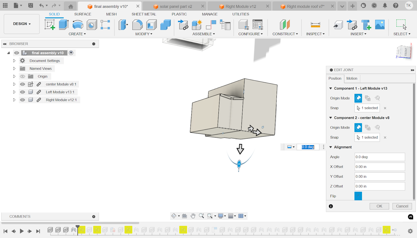
Press joint (shortcut j) and press on the back right corner of the middle module. Then connect it to the corresponding corner of the left module. Do the same thing for the right

Now connect the middle roof in a similar fashion. The back corner of the thin side touching the corresponding corner on the module

Now connect the left roof to the back corner of the left module and do the same thing for the right side.
Now you’re done !

Overall Design
With our build complete lets now outline all of the features included with it

The butterfly roof as explained before is great for maximum water intake as well as being very efficient for solar panels exposure.
The modular construction and 3d printed geopolymer paste allows for fast construction and deconstruction, saving time, money and effort.
The photochromic windows allow for the windows to be a great source of natural light but also not unnecessarily heat up the house and make AC run longer.

The Greywater recycling system is shown here for increased efficiency in water usage. Also the rainwater collection system.
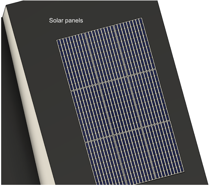
Finally solar panels take off the homes reliance from city power grids and allow the residents to have a steady flow of energy.
Greywater Recycling System
Every year, homes waste a huge amount of water, often thousands of gallons, on things that don’t actually need clean, drinkable water. This leads to unnecessary costs and puts extra stress on the environment. For example, why do we flush toilets with clean water when we could reuse water from washing our hands or doing laundry?
That’s why I designed my own custom greywater system to help reduce waste and make homes more efficient.

Before explaining how it works, it’s important to know what greywater is. Greywater is used water from sinks, showers, and washing machines, basically, water that’s not too dirty. Water from toilets or kitchen sinks is not greywater and can’t be reused because it might carry harmful bacteria or grease.

My system includes two filters and one main storage tank. The first filter removes larger particles using a carbon based filter, and the second filter uses a natural, biological process to clean the water further. At the very beginning of the system, a sensor checks whether the water is safe to reuse. If it’s not greywater, it automatically gets sent to the sewer. But if it is, it’s cleaned and saved for later use, like flushing toilets or watering plants.
This simple system can help save water, lower bills, and make a big difference in how we use resources at home.
Expansion
One big reason my housing design is affordable is because it can grow over time. Instead of building a huge, expensive house all at once, families can start small and then add new rooms or sections later as needed. This helps with affordability in a few key ways:
Lower Upfront Costs
You only pay for what you need right now. That means smaller loans, less stress, and faster construction. You can live in your home while slowly improving or expanding it over time. If money is tight, you can wait before adding another bedroom, office, or storage space. When you're ready, you can expand without having to move or start over.

Avoids Future Moving Costs
Instead of buying a whole new home when your family grows, you just build onto what you already have. That saves money on moving, closing costs, and even furniture.

Supports Changing Needs
Whether it's a new baby, a home business, or a roommate, expandable homes can grow to match your life. This flexibility makes your original investment go further.

My house incorporates this in the fact that floorplans are customizable with modules being able to be stacked on top of each other to have new rooms while all systems still remain functional. Using the Vertical space vs Horizontal space allows for a more efficient use of urban areas in Phoenix, Arizona.
This picture here is an example of the right attachable module being used for adding another floor to this house.
Potential Problems
Problem 1:
One potential issue with using a butterfly roof for rainwater collection is the increased risk of debris buildup in the central valley where water converges. Unlike traditional sloped roofs that shed leaves and branches to the sides, a butterfly roof funnels all rain, and any debris it carries, toward a single central gutter or downspout. Over time, this can lead to clogged drainage, and even roof damage if not properly managed.
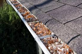
Solution: To address this, the design includes the implementation of a fine copper mesh over the gutter system, which acts as a physical barrier to leaves, twigs, and other debris while still allowing water to pass through. Copper is also a great antibacterial material on top of being rigid enough to be the mesh. This not only improves the efficiency and cleanliness of the rainwater collection system, but also reduces maintenance needs and extends the life of the roof infrastructure.
Problem 2: Another potential issue is the fact that we are using the natural skylight to preserve energy. While a great way for preserving energy, it can prove to be extremely inefficient for AC applications. Over time this can lead to Increased AC costs even though its completely avoidable.
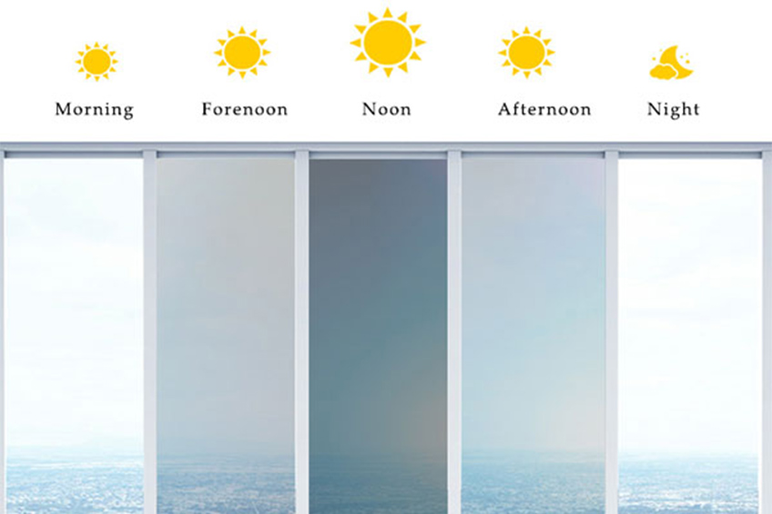
Solution: photochromic glazing is an ideal solution for preserving indoor cooling efficiency in regions that experience excessive sunlight and heat, especially during the summer. This smart window technologies automatically adjusts it's tint in response to changes insunlight intensity (photochromic), without the need for electricity or user input. When exposed to strong sunlight, the glazing darkens to reduce solar heat gain, limiting the amount of radiant heat that enters the home. This significantly reduces the load on air conditioning systems, helping to maintain cooler indoor temperatures while lowering energy consumption.
Floor Plan

Using the online tool homestyle I made a render of the indoor as well, with all the furniture, doors, windows etc. the bedroom has a master bed with a small table at the bedside. The bathroom has a shower with a toilet, a hanging rack and a sink. The laundry room has a simple washer and dryer. The kitchen has a stove, a microwave and a fridge. The living room has a small table and a tv on top of it and to the opposite side in the office, there is a small office chair and desk setup. Next the dining room with the table and chairs. Finally the storage and lounge rooms. These items do not come with the house and have to be bought and attached separately.
This is a video of me going through each room.
Costs
Right Module : $7,500 – $11,000
Middle Module : $3,500 – $5,000
Left Module : $5,500 – $7,500
Right Module Roof: $2,800 – $3,800
Middle Module Roof: $1,400 – $1,800
Left Module Roof: $2,200 – $2,600
Photochromic Windows for Modules: $1800 - $2400
Reflective Exterior Coating (heat-reflective paint): $300 – $500
Rainwater Collection Tanks & Piping - $500 - $1500
Carbon + UV Filtration System - $300 - $2500
Greywater Filtration System - $400 - $2000
Greywater Recycling Plumbing Setup - $250 - $800
Basic Electrical Wiring & LED Lighting: $1,200 – $1,800
Paint & Sealing: $500 – $900
Factory 3D Printing & Prefab Assembly: $2,500 – $3,500
Transport to Site: $800 – $1,200
Permits & Local Inspection Fees: $600 – $1,000
Connection Setup (water, power, greywater): $1,000 – $1,500
Minimum Total: $33,150
Maximum Total: $51,800
Printing It
Now comes the fun part, bringing my model to life. I will 3D print my model because it brings my design to life in a way that drawings or simulations can't. By creating a physical version of my house, I can test how different elements, like the roof angle, rainwater flow, and modular design, actually work together. It also makes it easier to explain the features of my project, like drought resistance, and modularity. Seeing the model in 3D helps me improve the design, fix small problems early, and show others exactly how it could be built in real life.
Unfortunately, the day I needed to print, my printer broke down. I lost hope for a little bit and decided to not even show the real model at all. That was until I realized that my friends had 3d printers. Supplying them with the filament, I gave them the files and let them print it for me. I made sure to tell them to scale it to 2% in their respective printers. I used a standard layer height that would allow for a realistic smoothness while still printing efficiently, and I chose a moderate infill to give the walls strength without wasting material. I also checked that all of the holes put into the wall were rendering correctly in the preview and wouldn’t close up or warp during the print.
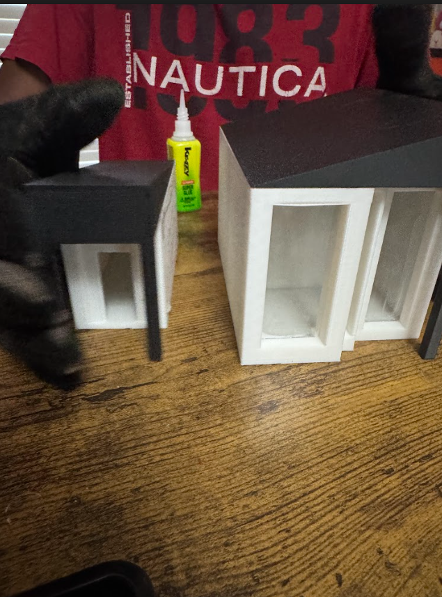
The modules

Now for the roofs, using the same procedure I made sure the long pillars were put under stress during the print. I selected extra infill but a smaller layer height for smoother lines.
The Roofs

I made my friends watch the first few layers in order to ensure proper adhesion to the build plate. Then once I ensured that I let him leave and waited for the print. Their house was around 40 minutes away so I had to start early in the morning and come back quickly. Once there I saw the print still running but only with a few minutes left. Once the print finished I let it cool for a few minutes, then I bent the build plate gently in order to get the modules off. For the supports, use a small plier to carefully pick off the tree supports. These tree supports will ensure no leftover support material.
Getting Ready
First thing you are going to do is get all the materials you need: gloves for safety, eye protection, Krazy all purpose glue, scissors, clear acetate sheets (you can get them at michaels), ruler and sandpaper
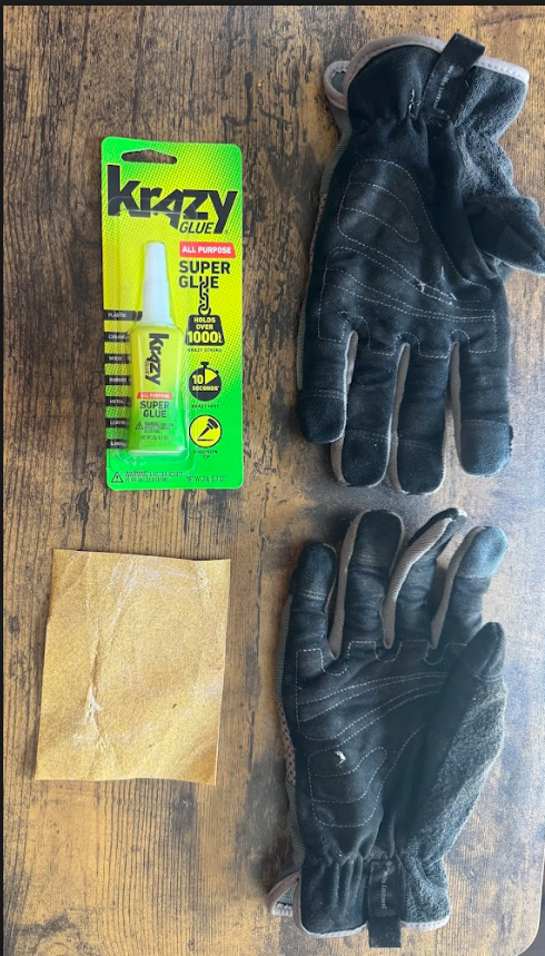
Remember safety always comes first
Putting on Windows
Step 1)
First take your clear acetate sheet and cut as shown

The left 3 are for the right module and the right 3 are for the left module. Well work with the Left module for now.
Step 2) Left module
First thing we have to do is fold the 1.3 x 3.7 piece. Fold longways at 0.8 inches from the edge

Position the piece flush against the wall of the window. Next, get something long to hold the bottom of the acetate sheet in. Finally put some glue on the top and stick it to the acetate piece while maintaining grip on the bottom. Finally once it's fully stuck, put some glue through the bottom of the window, where the acetate sheet and module meet, and glue it flush. Finally on the folded piece, glue it to the corresponding wall. For the second window use the 0.7 in x 3.3in piece and cut as shown

Once done line it up flush against the window position and repeat the steps from before, except without the folded part.
Finally for the third window, no modifications have to be made. Just position the sheet and glue accordingly
Step 3) Right module

Luckily this side is much easier, because it is the same process with just another module. For the 1st and 3rd windows follow the same procedure as normal. However for the 2nd one you have to cut the same size holes as before. After that, glue it according to the shape of the window. Remember 1st window: 1.5 x 3 in, 2nd window: 0.7 in x 2.6 in, 3rd window: 1.2 in x 3 in.
Left Module Assembly
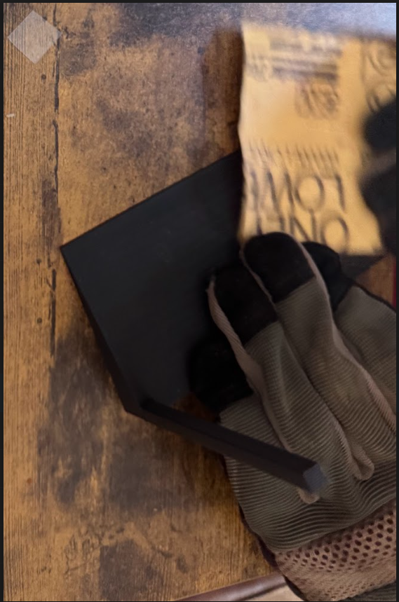
Before doing anything we have to sand the connection points down in order to ensure strong connection for further use.
I started with sanding the roof
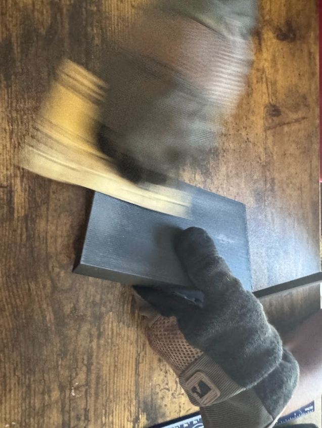
Then the module

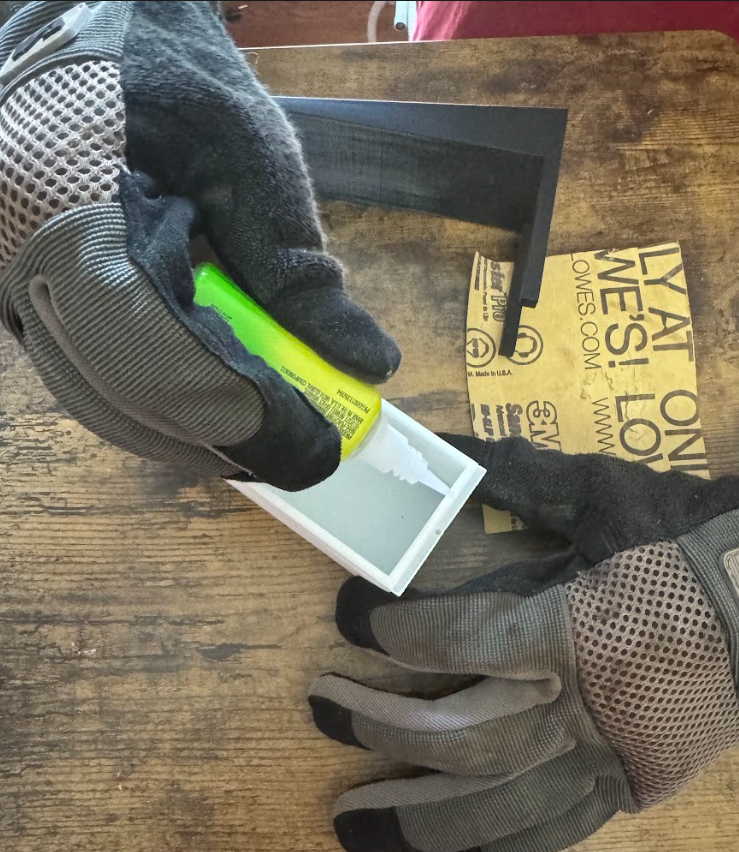
Finally I added glue to the connection points. Make sure it is spread out evenly to prevent oozing and inconsistencies.

Next position the roof onto the module, making sure the edges line up perfectly. Make sure to do this step fast because the glue dries really fast.

While doing this I realized its not super smart to line it up with my hands so I used a ruler instead for the next module.
Right Module Assembly
First sand all connection points on the roof
Then all of them on the module

Finally add glue to all connection points. Once again make sure the glue is spread evenly across all contact points with the roof.

Finally position the module perfectly so that the edges line up. This time with the straight edge for reference.

Center Module Assembly
First sand all connection points on the roof

Next the module

Spread the glue evenly on all connection surfaces for the module
Finally position the roof so that the thin edge of the roof matches up with where the gutter starts and the module ends.

Assembling the Whole House
First sand both sides of the middle module making sure that there is a flat surface for the glue to bond.

Next for the right module sand the connection surface on the left side and for the left module sand the connection surface on the right side. Directions given assuming that the windows are facing you.

Next apply glue onto the right side of the middle module. Assuming the door is facing you.

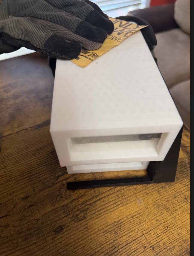
Finally position the middle module so that the edges line up on the back. The gutter should be jutting out of the back, not kept at the edge of the right module. Once again make sure to be fast.
This clearly shows the position needed

Now do the same thing for the other side of the middle module


Once again the positioning of all 3 modules

Now cut a little bit of the brown mesh and place it on the gutter. This will act as the copper mesh for the gutter. We will not need it for the next test. However if you wish you can put it on, it will make no difference because its a mesh.

Apply glue on the edges of the gutter as shown.
You’re done!
Testing the Model
Now that you're done with the model, it's time to test the efficiency of it. In order to do this experiment I need to have a set amount of water and see how much of the water it collects. In order to do that I used a bowl and filled it to the brim. For simplicity we will be measuring water amount with straw height.

Next for the project setup. You will place your model on an elevated surface in the sink. Under the gutter pipe put a bowl of the same kind that has the water.
Finally we need to make a rainwater simulation. To do that I simply poked holes into a ziploc bag and put the set amount of water into it. Finally I put the water over the model and compressed the ziploc bag gently.
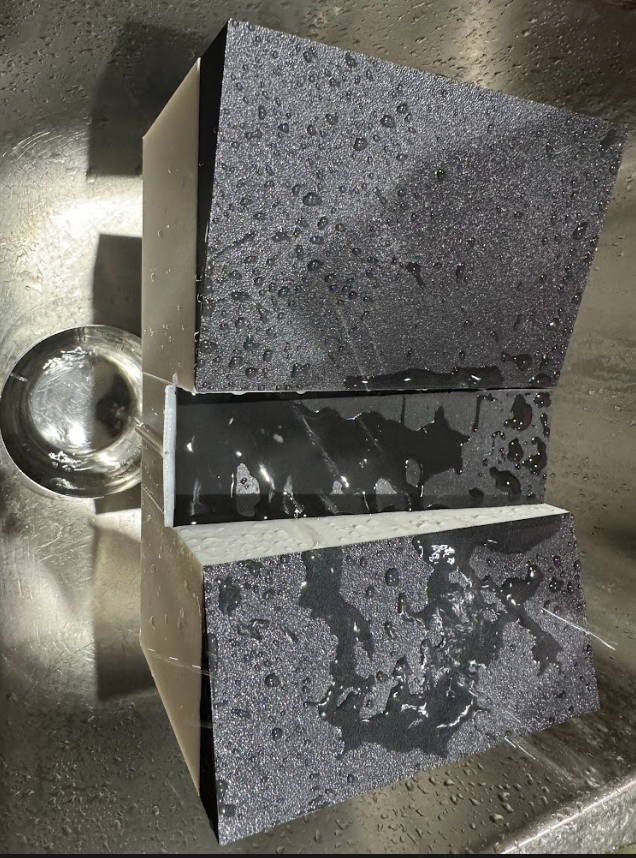
When all the water was gone I measured the amount in the cup.
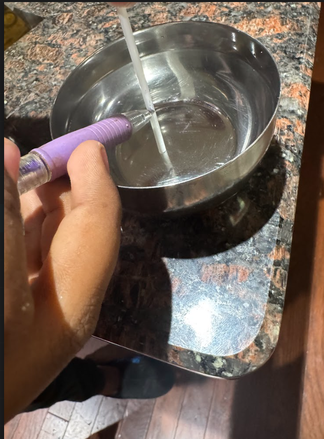
You can see the difference in straw heights here. The one on the right is original and the one on the left is how much it picked up. Overall, the model performed really well. After analyzing straw heights, the one on the left is 1.7 in while the one on the right is 1.3 which means the system picked up more than 75% of the water dropped. This is extremely impressive, especially with the amount of water that was left on the roof, which is unavoidable.

Reflection
From digital design through physical modeling, the tools that enabled me to realize my ideas have made this whole project possible. I would like to acknowledge the software, hardware, and supplies that carried me through months of trial and error (and a lot of CAD).
Fusion 360 by Autodesk
From day one, my primary workhorse. Every module, roof, and system began here. Breaking down the design and constructing it bit by bit was made simple with the use of extrusion, fusing, and assembly tools. Working out every dimension of this modular home needed was made incredibly easy with this perfect intuitive tool.
3d Printer
Although I had intended to print the model on my own printer, when it failed my friends came to my rescue with theirs and I am very appreciative of that. The physical model came to life because of their machines, whether it was PLA, tree supports, or bed adhesion drama.
Bambu Studio
Finding the correct balance of quality and velocity took a lot of trial and error adjusting slicer settings in Bambu Studio. Especially making sure there was no possibility of warping or closing up for any of the windows. Overall although I started with no intention of even using the tool, I came out feeling very comfortable with the application.
Modelling Equipments
Nothing fancy — just some basics that made a huge difference:
Sandpaper to clean connection points
Krazy Glue for strong bonds
Ruler for lining everything up
Clear acetate sheets for the windows (shoutout to Michaels)
Small pliers to remove supports without damaging walls
Forums and YouTube
Though not quite a downloadable tool, I leaned on it almost every day. At every step, I found assistance from tutorials, Reddit threads and Fusion groups in solving issues.
Acknowledgements
I only wanted to briefly express my gratitude to the people who made this effort feasible:
To my friends big cheers for arriving with your 3D printers when mine gave up on me completely. Letting me use your setups, assisting with the prints, and being extremely patient—especially with all my irritating follow-up messages—you truly saved the day. I owe you greatly.
To my parents: Thanks for enduring the late nights, haphazard parts scattered throughout the house, and infinite chatter about greywater and rainwater systems. Your encouragement means a lot; I could not have gone on without your cheering me on (and occasionally reminding me to go outside and touch grass).
I really appreciate Autodesk and the Instructables team for enabling free tools like Fusion 360 for students and providing us with a forum to actually express our ideas. This competition was the drive I needed to make an idea from my head into something concrete, and I have grown far more than I ever anticipated through this process.