Modular Desktop Explorer Robot
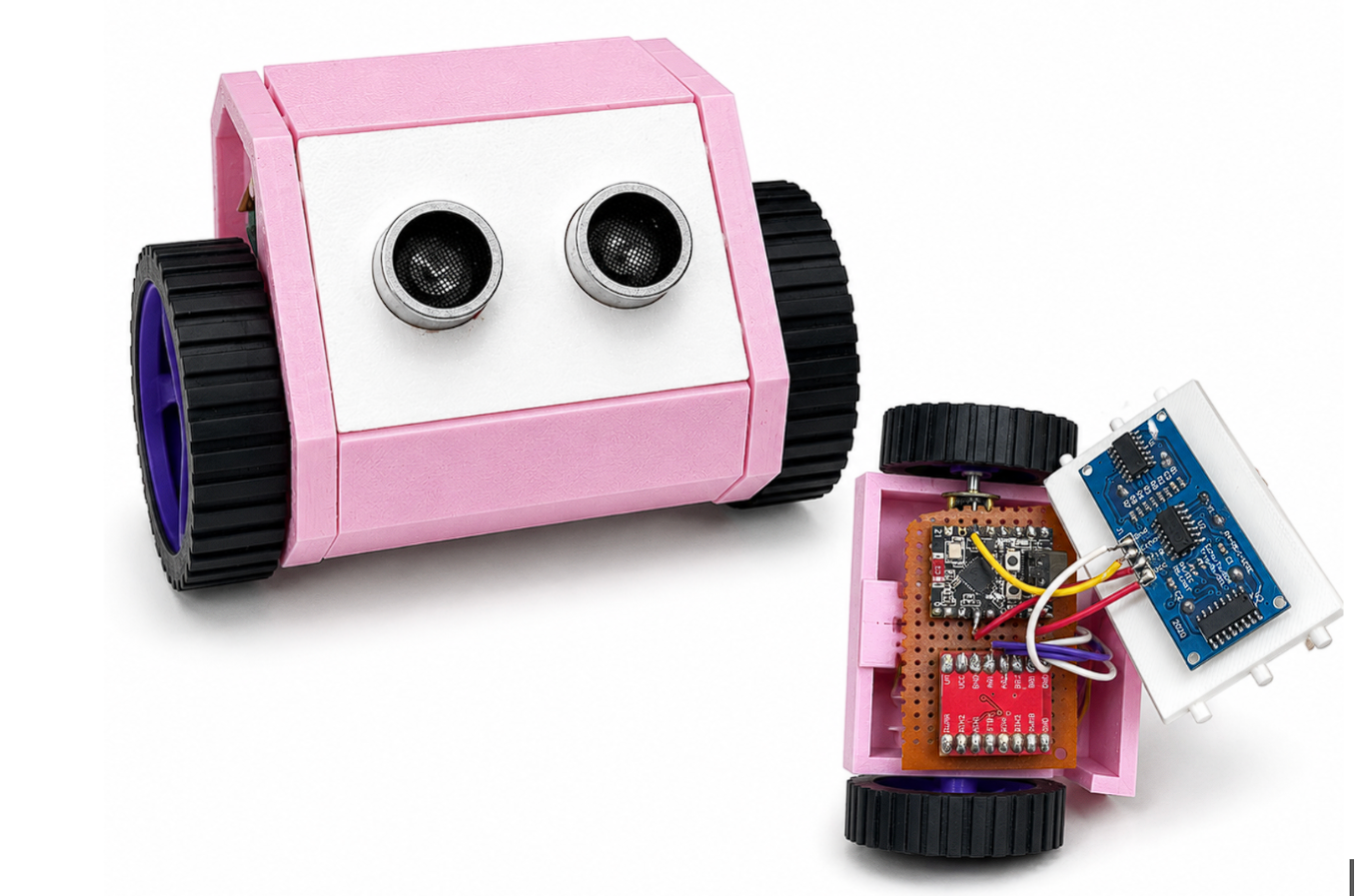
When I first started learning robotics, I really wanted to figure out how hardware sensors actually talk to the environment instead of just building another standard remote-controlled toy. I stumbled across a video by a creator named Huy Vector called I Made a Tiny Robot That Explores My Desk, and I completely fell in love with how compact and clean it looked. I wanted to take that exact aesthetic inspiration and see if I could turn it into an autonomous, obstacle-avoiding robot.
To keep things neat and easy to duplicate, I decided to design a modular shell using Lego-style snap-fit joints in Autodesk Fusion. Instead of making one solid 3D-printed block, the design uses two outer frames that sandwich the chassis panels together.
This whole project turned out to be a massive learning curve for me, full of trial and error, tight tolerances, and a lot of hardware troubleshooting at MakerWorks. I wanted to write this down to share everything I picked up along the way, so you can take these ideas, lessons, and code and use them however you want for your own builds!
Supplies
Here is the exact breakdown of materials I gathered for the build:
- Microcontroller: ESP32-C3 SuperMini because it has a tiny footprint that takes up barely any space inside the chassis.
- Motor Driver: TB6612FNG Dual H-Bridge module to manage our motor channels.
- Actuators: Two N20 micro geared DC motors.
- Sensor Array: One standard HC-SR04 ultrasonic sensor.
- Power Storage: Two 3.7V Lithium Polymer batteries because they are easily rechargeable, and they were the only non-bulky option I could find around the lab at the time.
- Power Management: One mini DC-DC buck converter and a simple mini SPDT slide switch.
- Workshop Spares: Two standard rubber-rimmed wheels from the makerspace spare parts bin and one tiny free-moving 360-degree caster wheel.
- Wiring Strategy: A sacrificial multi-core data cable. Cutting it open gives you an array of thin, flexible internal wires that can be bent easily in tight directions to fit everything into the chassis perfectly.
- Miscellaneous: Basic masking tape and a standard soldering setup.
- Software Environment: Autodesk Fusion for modeling, Bambu Studio for slicing, and the Arduino IDE for code development.
What I Learned About Slicing and Design Assemblies
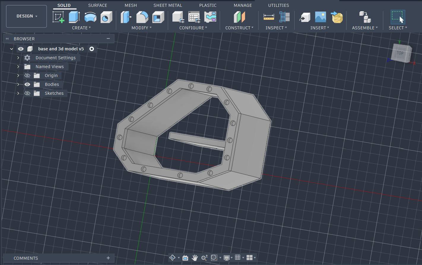
The structural assembly relies entirely on two parallel outer frames, between which the individual chassis panels are securely sandwiched to keep that compact look. Here are the core design and manufacturing choices I learned to manage:
- Clearances for Snap-fits: You have to play around with test prints to match how your specific printer handles plastic expansion. Working with my printer profile inside Bambu Studio helped me understand the exact clearances needed for a clean friction fit.
- N20 Motor Sliding Depth: A major consideration was figuring out the exact distance the N20 motors needed to slide inside the chassis slots. If you do not calculate this depth correctly, the rubber wheels will end up brushing or rubbing against the outer chassis panels when press-fit onto the D-shafts.
- Wire Routing Slots: I made sure to leave a dedicated wire exit slot at the back of the motor mounts so the power leads wouldn't get pinched by the spinning components.
- Print Orientation Rules: You want to make sure you print any cylindrical snap-fit pins horizontally along the print bed instead of standing straight up. 3D prints are inherently weaker between layers. Vertical pins create a perfect shear line, causing them to snap clean off under impact. Printing horizontally forces the extruded plastic lines to run the whole length of the pin, making it structurally sound.
Feel free to download the stl files I attached to this step and tweak them however you like.
Moving From Breadboard to the Perfboard Battle
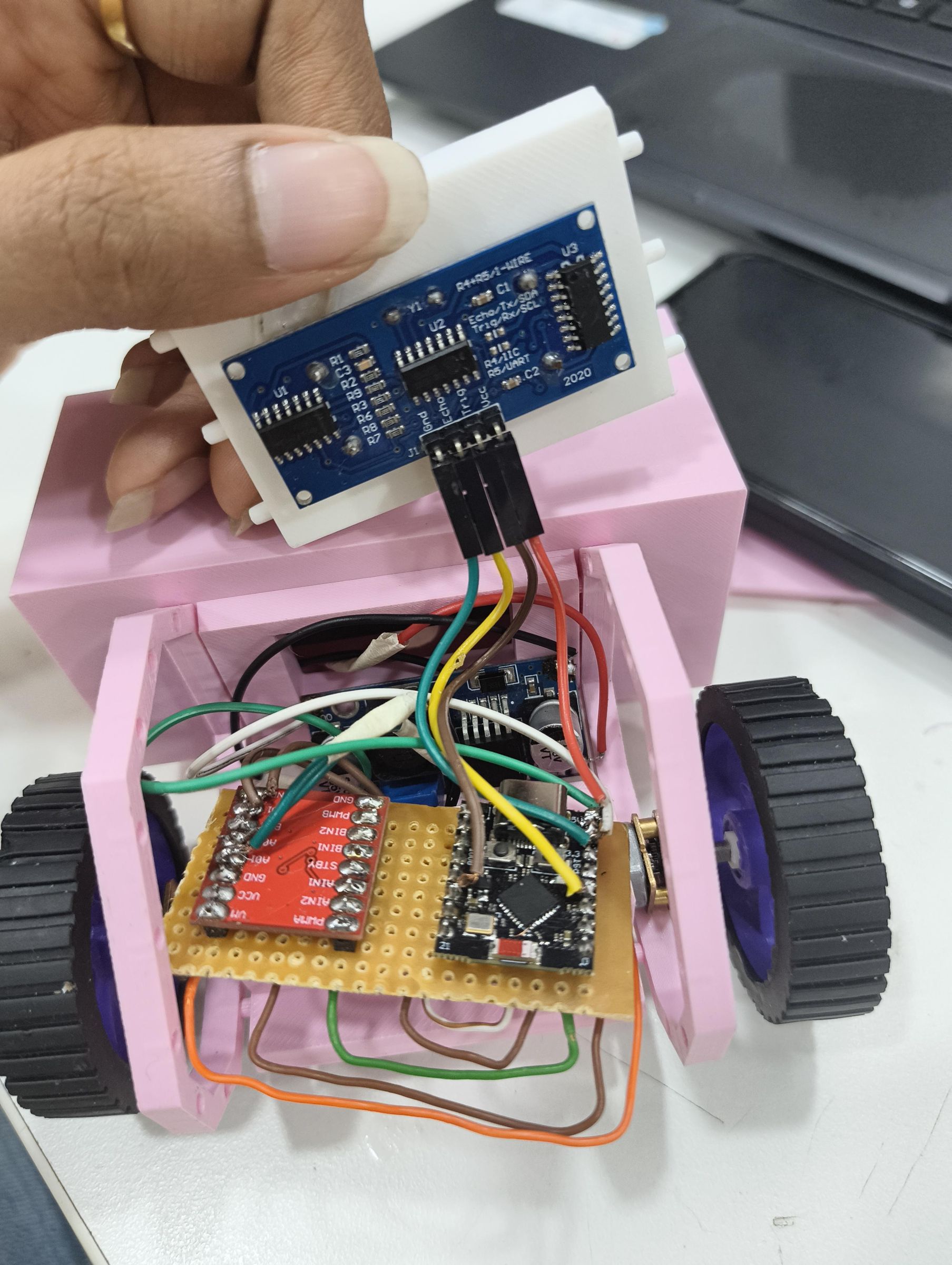
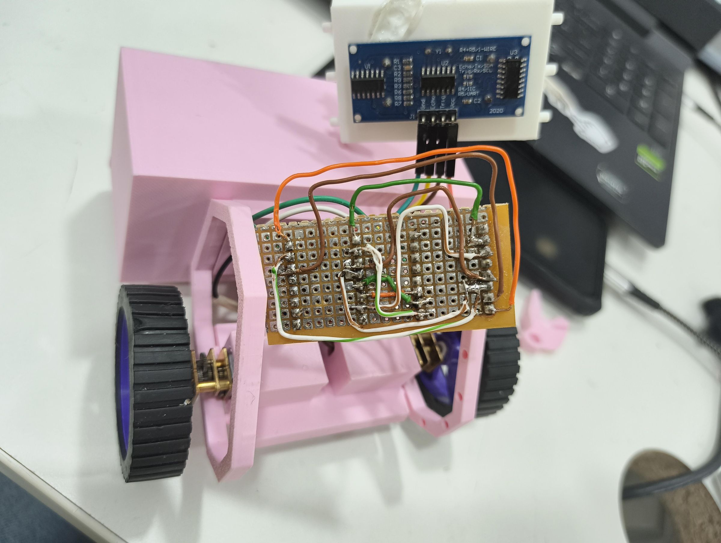
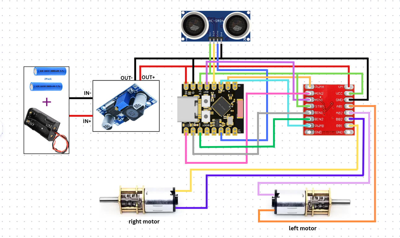
I started by mocking up the circuit on a plastic breadboard to make sure the logic worked. Here is the process and the mistakes I encountered while making the final electronics panel:
- Stripping Unnecessary Parts: In the beginning, I actually added a tiny LED screen to try and match the face from the inspiration video. But I quickly realized the screen didn't serve any actual purpose for an autonomous robot, so I stripped it away to focus entirely on the ultrasonic sensor.
- The Risk of Overheating: Swapping the loose breadboard wires for a permanent perfboard circuit took the most time. On my first attempt, I used regular jumper wires, but having to attach, test, and desolder them multiple times completely overheated and ruined my first motor driver chip. Using the thin data cable wires saved the second attempt.
- Sensor Isolation: I left the ultrasonic sensor wires completely detached from the main perfboard during this soldering phase, which made troubleshooting the rest of the board way easier.
- Split-Voltage Power Rail: Connecting two LiPos in series gave me about 7.4V. Since you cannot feed that raw voltage straight into the microcontroller or the sensor, I split the power rail. The raw 7.4V goes straight to the motor driver's VM pin to give the N20 motors maximum power, while a second branch passes through the buck converter to drop the voltage down to a safe 5V for the ESP32-C3 and the ultrasonic sensor.
Figuring Out the ESP32-C3 and the Code
Programming the compact ESP32-C3 SuperMini inside the Arduino IDE requires a very specific setup sequence, as computers often fail to autodetect the board over a standard USB cable. Here is how I debugged the system:
- Triggering Bootloader Mode: You have to hold down the physical BOOT button on the board, press the RESET button once, and then let go of the BOOT button to force the port open.
- Crucial Arduino IDE Setting: You must go into the Arduino IDE settings under Tools and make sure USB CDC On Boot is set to Enabled. If you leave it off, the board completely shuts down serial communication once the code starts running, which means you won't be able to read any of your serial debug printouts.
- Evasion Logic: For the code, I kept it entirely focused on obstacle avoidance at a strict 15cm threshold. The robot cruises forward until the sensor sees something closer than 15cm, at which point it pulls all direction lines low instantly to trigger a hard electromagnetic brake. Then it reverses for a moment and reads the internal system clock using millis. By checking if the current millisecond is even or odd, the robot makes a completely randomized 50/50 choice to pivot left or right to escape the obstacle.
- Avoiding Wide Sweeps: I chose not to add a complex full turnaround routine because with just one single forward-facing sensor, the robot is totally blind to its sides and back. Trying to make wide, sweeping turns without knowing what is next to you just means crashing into things, so a quick randomized pivot backward and away was the easiest, cleanest fix.
Here is the exact code block you can copy directly into your workspace:
Downloads
The Final Assembly
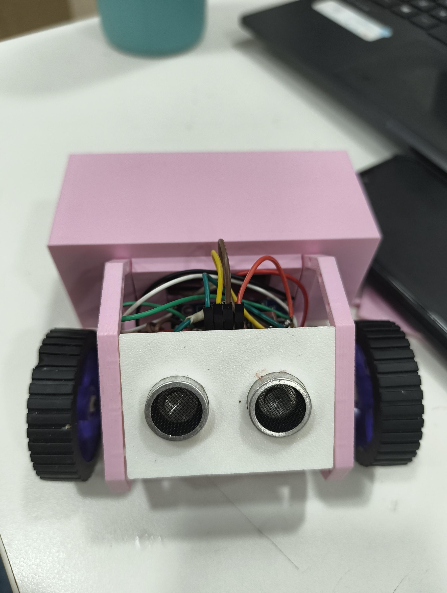
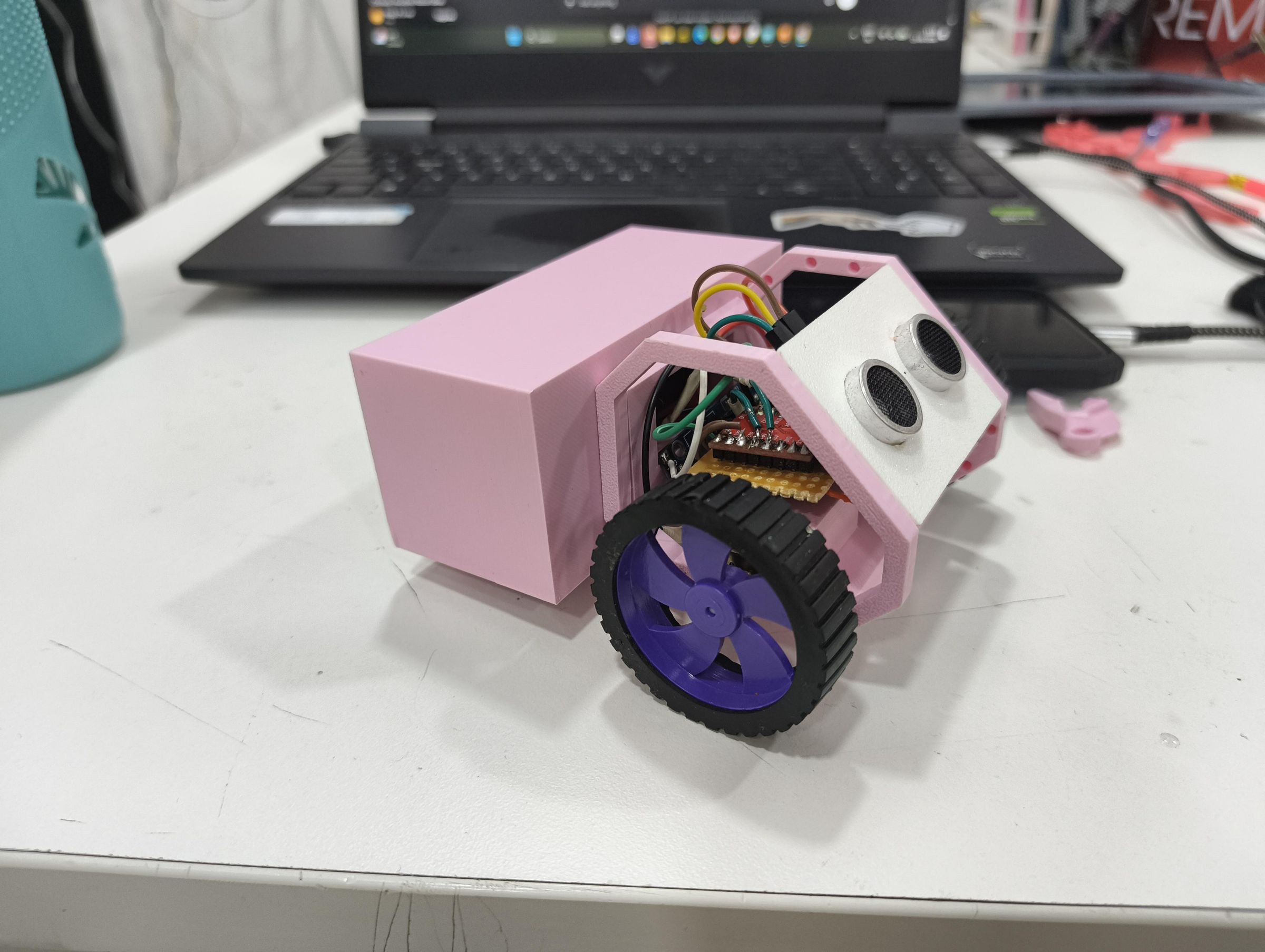
You would think assembling a snap-fit robot would be the most satisfying part, but it actually turned out to be pretty annoying. Even though the panels fit perfectly at the base, trying to hold everything together to get the top structural chassis to lock in without everything popping open was a real struggle. Here is the assembly pipeline I used to secure it:
- Setting the Foundation: If you look at the robot sideways, the frame splits into a base layout and a top layout. I pushed all the internal components and the N20 motors tightly into the lower section of the frame first.
- Securing the Base Panels: I attached the side panels to the base frame tracks first so they were anchored correctly.
- The Masking Tape Trick: I tightly wrapped basic masking tape around this lower section to hold the panels perfectly flush. This stopped them from flaring open or appearing frayed at the top section.
- Capping the Shell: With the masking tape holding the bottom tight, I was finally able to press the upper frame down over the top to compress and lock the whole chassis together perfectly.
- Modular Battery Carriage: To finish off the battery setup, I made the base modular so the custom rear battery carriage slots right into the main frame just like the rest of the Lego-style pieces.
- Adding a Caster Wheel: Because the batteries added a lot of weight to the back, I attached a small, free-moving 360-degree caster wheel right under the carrier so it could roll around without tipping over.
- Switch Integration: I also wired in a mechanical side switch so I could turn the whole thing on and off instantly without messing with the power cables.
Once everything is snapped together, you just flip the switch, put it on your desk, and watch it explore.