Mood Lamp With Arduino
by ricardouvina in Circuits > Arduino
134322 Views, 236 Favorites, 0 Comments
Mood Lamp With Arduino


Hi! In this tutorial you will learn to make a mood lamp with arduino.
I know that you may have seen a lot of mood lamp projects with arduino, but I wasn't very satisfied with them because they all change the color very abruptly. So, I decided to make a smooth mood lamp and I also made it to turn on only when the room is dark.
This project is good for those who are beginners in the arduino's world.
Material

For this instructable you are gonna need:
- Arduino
- Jumper wires
- 1 RGB LED or 1 red LED, 1 green LED and 1 blue LED
- LDR (Light Dependent Resistor)
- Protoboard
- Sheet of paper
- Arduino
- Jumper wires
- 1 RGB LED or 1 red LED, 1 green LED and 1 blue LED
- LDR (Light Dependent Resistor)
- Protoboard
- Sheet of paper
Time to Code!
Write the code above on the Arduino program.
Darker the ambient light is, the higher is the value read from the LDR.
I used PWM to change led's brightness.
// Smooth RGB mood lamp
// Changes an RGB LED's color smoothly that only turns on
// when it's dark around it.
// Author: Ricardo Ouvina
// Date: 19/07/2012
// Version: 2.0
// ---------------------------------------------------
// The brightness of the leds follows these equations:
// Red = sin(x)
// Green = sin(x + PI/3)
// Blue = sin(x + 2PI/3)
// for x from 0 to PI
// ---------------------------------------------------
float RGB[3];
int ldrPin = 0; // LDR in Analog Input 0 to read the ambient light
int ambientLight; // variable to store the value of the ambient light
int redLed = 11; // red LED in Digital Pin 11 (PWM)
int greenLed = 10; // green LED in Digital Pin 10 (PWM)
int blueLed = 9; // blue LED in Digital Pin 9 (PWM)
void setup(){
pinMode(redLed,OUTPUT); // tell arduino it's an output
pinMode(greenLed,OUTPUT);// tell arduino it's an output
pinMode(blueLed,OUTPUT); // tell arduino it's an output
// set all the outputs to low
digitalWrite(redLed,LOW);
digitalWrite(greenLed,LOW);
digitalWrite(blueLed,LOW);
}
void loop(){
for (float x=0;x<PI;x=x+0.00001){
RGB[0]=255*abs(sin(x*(180/PI))); // calculate the brightness for the red led
RGB[1]=255*abs(sin((x+PI/3)*(180/PI))); // calculate the brightness for the green led
RGB[2]=255*abs(sin((x+(2*PI)/3)*(180/PI)));// calculate the brightness for the blue led
ambientLight=analogRead(ldrPin); // read an store the ambient light
if(ambientLight>600){ // start only if the ambient light is very low
// write the brightness on the leds
analogWrite(redLed,RGB[0]);
analogWrite(greenLed,RGB[1]);
analogWrite(blueLed,RGB[2]);
}
else{
digitalWrite(redLed,LOW);
digitalWrite(greenLed,LOW);
digitalWrite(blueLed,LOW);
}
for(int i=0;i<3;i++){
if(RGB[i]<1){
delay(100);
}
if(RGB[i]<5){
delay(50);
}
if(RGB[i]<10){
delay(10);
}
if(RGB[i]<100){
delay(5);
}
}
delay(1);
}
}
Downloads
Connect It!
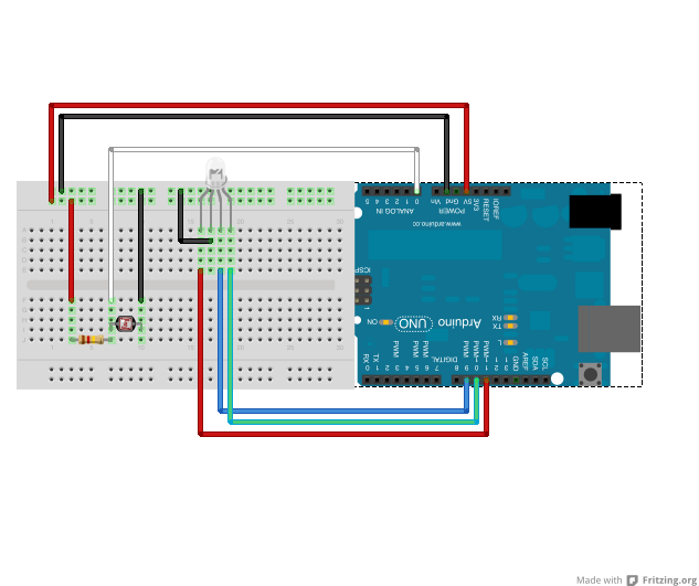
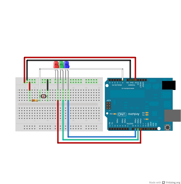
Connect as it is on the image.
Upload and It's Done!
Upload the code to the arduino and it's done.
Try to add a sheet of paper around it to see it more smoothly, the paper acts as a diffuser.
Feel free to modify this project to your way, and tell me your progress. Comments are welcome.
Have a look at the video I've made.
Try to add a sheet of paper around it to see it more smoothly, the paper acts as a diffuser.
Feel free to modify this project to your way, and tell me your progress. Comments are welcome.
Have a look at the video I've made.