Moon Phase Display Based on Observer's Location on Earth (updated 2025-10-21)
by pgeschwi in Circuits > Arduino
236 Views, 3 Favorites, 0 Comments
Moon Phase Display Based on Observer's Location on Earth (updated 2025-10-21)

I'm a hobby stargazer and in some discussions with friends, I found that some did not notice the moon changing its angle of the illuminated limb throughout its path. Since Minnesota is not a friendly state for us astronomy fans, I thought about visualizing moon phases as they appear in the sky, adjusting for the observer's position on Earth. Usually, moon phases are shown universally, progressing horizontal, with the axis of the moon always north/south.
(This instructable has been updated as promised using a 480x320 touch screen display. Changes are incorporated into the text where needed and a new display box with pictures have been added. 2025-10-21)
So, here is one which corrects this deficiency:
Features
- Displays 40 moon phase images (at 9-degree increments) with realistic progression over time.
- Takes the observer’s location into account to tilt the illuminated limb correctly.
- Uses formulas from Jean Meeus' Astronomical Algorithms (1998).
- Just for the giggles, I included Black/Blue Moon date calculations—added for fun since some of the necessary data was already present for moon phase calculations.
The Sketch is written for ESP32. A traditional Arduino does not have the storage/RAM and also lacks the required precision (double float). The ESP32 does not have a hardware floating point unit capable calculating double float either, but the math library will emulate double precision. This of course is at the expense of speed, but we're not in a hurry and the calculation is done only once a minute.
When calculating moon phases, using the long term average of 29.53 days per moon cycle, single float precision is OK, but this would prevent us from getting reliable results for the blue moon date/time calculation.
Astronomically irrelevant, but a fun fact to know when the next black/blue moon appears:
Black Moon = The second new moon in the same month
Blue Moon = The second full moon in the same month
Seasonal Blue Moon = The third full moon in a season with four full moons. A season is the time (quarter) between equinox and solstice and vice versa.
BTW, blue moons appear about every 18 months to 2.5 years, but there are exceptions. In 2018, January and March had a blue moon the same year.
The code is modular and can be dissected/reduced to the level you'd like to implement. Most of the routines can be used outside this project as long the right parameters are supplied. Whoever worked with Arduino/ESP32 should be able to pull parts out and use for their own purpose. Some routines I got from open sources in the astronomy forums and adjusted for my purposes. Special credits go to
- Greg Miller - www.celestialprogramming.com
- Giuseppe Cardillo - www.mathworks.com/matlabcentral/fileexchange/17977-equinoxes-and-solstices
- Dan Cross - the most comprehensive library of astronomical open source libraries I know, also available for multiple programming languages. github.com/cosinekitty/astronomy
Supplies


The parts list is pretty short. We'd need a display (I used two which I had in the junk drawer), use any of the commonly used ones and adjust the driver reference in the TFT_eSPI library if needed for a different type. More below on how this is done. I used 2x ILI9341 with a resolution of 240x320, which gives us plenty room. I used one for the text info and the other for graphics. If you like to use a single, bigger display, your choice may be one with a resolution of 480x320, saving you the hassle driving two individual displays. A matching link is in the parts list below.
If the display (like the one I used) has a SD-Card reader, you don't need one extra, otherwise a SD card adapter or micro SD-Card reader is needed. The SD-Card will carry the 40 PNG-Images of the moon phases. These are traditional moon phase images, north/south oriented which will be rotated to show the actual illuminated limb.
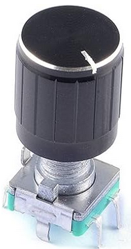
To adjust settings we'll use a rotary encoder with push-button.
Finally we'd need a RTC (Real-Time-Clock) to keep time while the system is switched off. Clock precision is not of utmost importance, there is no big change if the clock is a couple of minutes off. The RTC is running on UTC, all calculations are based on UTC anyways. The time zone settings are affecting displayed dates/times only.
Parts list:
- ESP32 Dev-Board or similar (minimum is a version with 30 or more pins):
- https://www.amazon.com/Development-AYWHP-ESP-WROOM-32-Bluetooth-Compatible/dp/B0DG8JFY3C/ref=sr_1_10
- Display: (it looks like that non-touch-sensitive versions are hard to get nowadays. I guess one can take the challenge, drop the encoder and make setting changes via the touch screen):
- https://www.amazon.com/XIITIA-Display-ILI9341-240x320-Screen/dp/B0CJHPRFGF/ref=sr_1_11
- https://www.amazon.com/DEVMO-ILI9341-Display-240x320-Raspberry/dp/B07WR48MVD/ref=sr_1_3
- https://www.amazon.com/Hosyond-Display-Compatible-Mega2560-Development/dp/B0BWJHK4M6/ref=sr_1_7_sspa (4in + 3.5in displays are using the higher resolution)
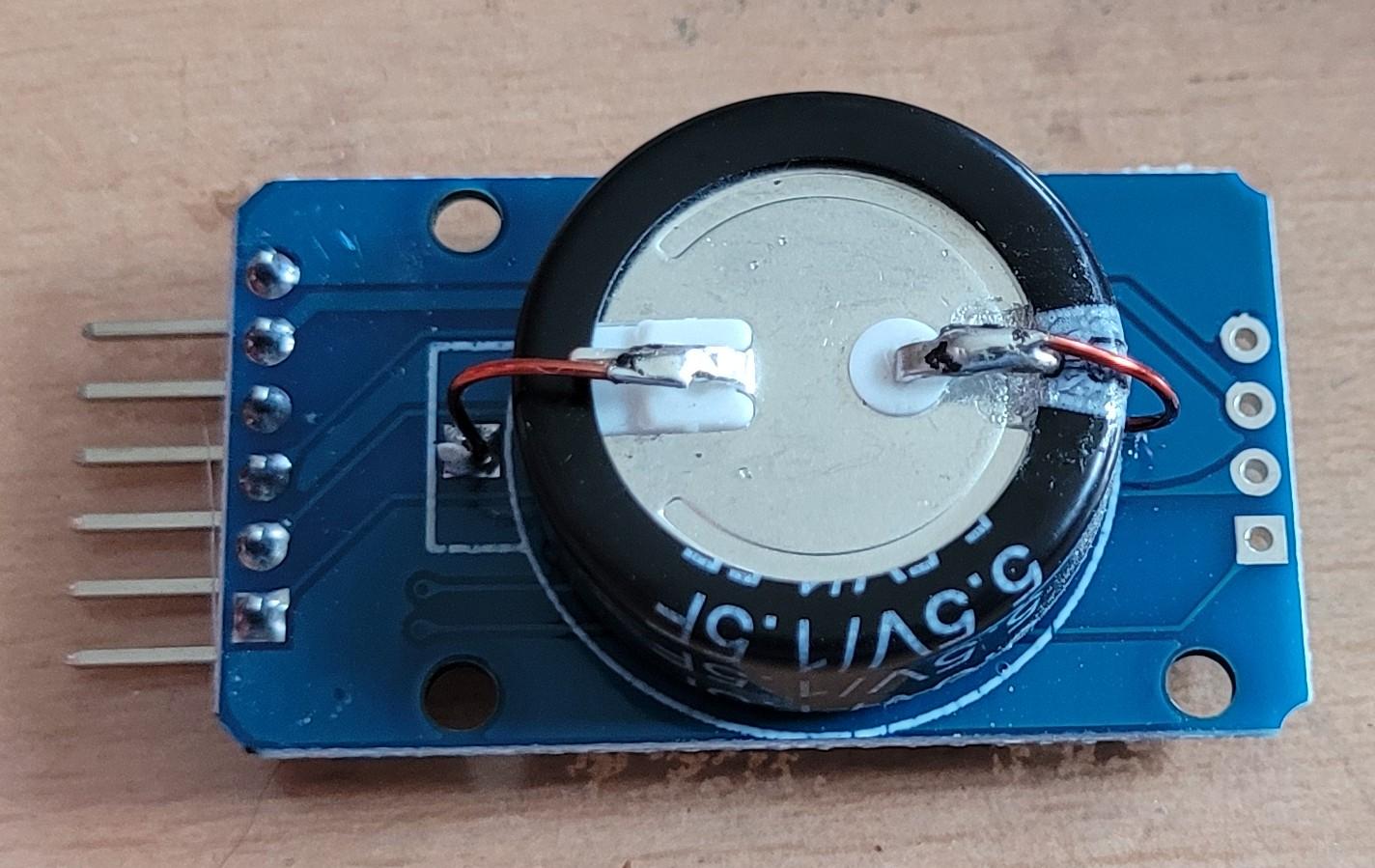
- RTC (this is the one I used, but this has a design flaw. It is intended to use a LIR2032 which is continuously being recharged. The problem is that the cell is constantly overcharged and killed after a couple of months. I replaced the battery holder by a 1.5F super-cap which is the better solution, picture above):
- https://www.amazon.com/AITRIP-Precision-AT24C32-Arduino-Raspberry/dp/B09KPC8JZQ/ref=sr_1_1
- Encoder:
- https://www.amazon.com/Cylewet-Encoder-Digital-Potentiometer-Arduino/dp/B07DM2YMT4/ref=sr_1_1_pp
- SD-Card Reader (if the display in use does not have one):
- https://www.amazon.com/HiLetgo-Adater-Interface-Conversion-Arduino/dp/B07BJ2P6X6/ref=sr_1_1
Wiring
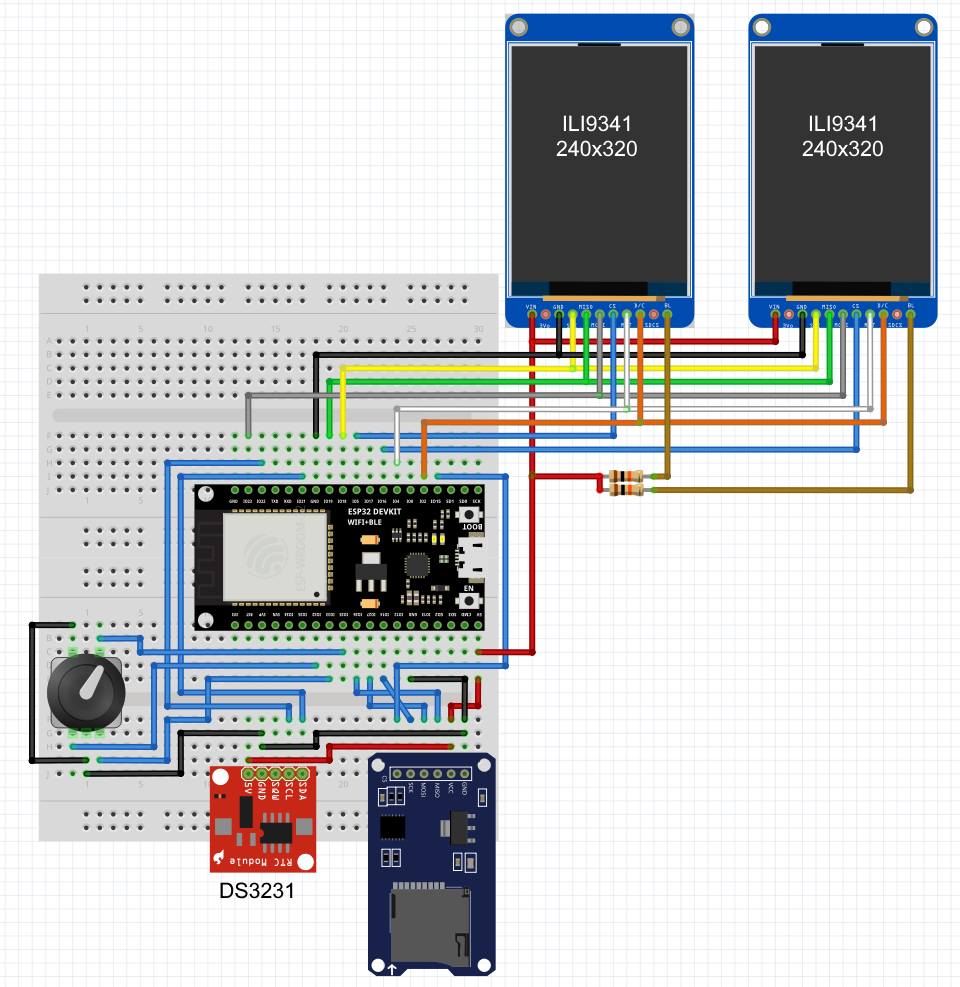
Wiring is straight forward as shown above, detailed pin assignments are also shown in the sketch. Driving two displays using the same library can be done by using different CS (Chip Select) pins independent from the library. The library in use is 'TFT_eSPI' which is an universal approach for many different display modules, but it's getting finicky if you want to drive two different types of displays.
The two displays in use are wired in parallel, only the CS pins are separated. In the sketch, I select the correct display by writing a '0' (CS is low active) to the matching pin.Using a larger screen avoids these added hoops, but you would also need to adjust the position references for graphics shown on the secondary display.
It should only take a couple of minutes to put everything together on a breadboard. I created a little case for those who are interested.
Here is the link to tinkercad if one likes to remix it:
https://www.tinkercad.com/things/01KVY4onpfN-moon-phase-observer-view-box
Libraries and Settings, Code Upload
Before we can get the code uploaded, we need the required libraries installed. All required libraries are easily installable via the search window in the Arduino IDE. Those who never worked with ESP32 before, need the ESP board + package as well:
- Boards manager:
- search for 'esp32' and install 'esp32 by Espressif Systems'
- Library manager
- search for 'tft_espi' and install 'TFT_eSPI by Bodmer'
- search for 'pngdec' and install 'PNGdec by Larry Bank'
- search for 'rtclib' and install 'RTClib by Adafruit'
- search for 'esp32rotary' and install 'ESP32RotaryEncoder by Matthew Clark'
- SPI, SD and Wire library should be already installed
The only Library requiring some special attention is TFT_eSPI. Unlike most others, the settings for pins and hw-chipsets are done in 'User_Setup.h' inside the library folder. The two sections which may need changing are the chipset and the corresponding pins. The first part is the driver section, beginning around line 44. Only one type should be active (uncommented) and should look like this:
The second section defining the pins starts around line 209 for the ESP32 world. There are plenty other MCUs listed. This makes the library very flexible but admittingly somewhat confusing to setup, making sure you are manipulating the right category..
Below are the pins I used.
Everybody who has worked with ESP32 will probably stumble over the CS-Definition. This is set to pin 35, which is an input-only pin and would be unable to drive the display. In this particular case I am driving two displays and use a single instance to drive both. Selecting the correct display is done in the actual code by manipulating the CS-pins accordingly.
The two pins in use to drive the displays in my sketch are:
This is all we need to prepare for compiling the sketch and upload. One display should show text information and the other the moon and below the relative position of sun, moon and earth.
All required files, sketch and SD-Card images are stored in my Github repository at:
https://github.com/pgeschwi/Moon-view-based-on-observer-location
If you get an error while compiling the sketch about a missing "bb_spi_lcd", just use the library manager to install this library with the same name as well, no need to change anything in the sketch.
The files for the SD-Card are located in my Sync-Share here:
https://ln5.sync.com/dl/a5887c800/45f8q88z-ke4hpde5-7qhafa2n-6ftg3qvi
Update:
I ran into an issue with newer versions of the PNGdec library, which is throwing compile errors when using versions above 1.1.3 (up to 1.1.6 at time of the update). Please use the older version 1.1.3.
When using the single display (480x320) there is no need using the tricky manual screen update via the separate CS-Pins. All changed Pin settings are explained in the sketch file. The bigger display I used is also a different controller, type ST7796.
Operation and Settings
If the RTC has not been in use with this sketch, initial default values will be written to NVRAM. The three items stored in NVRAM are
- Time zone
- Observer's Latitude
- Observer's Longitude
The initial time zone setting is US-Central Time, and the location of Minneapolis. Lat/Lon is stored as full degrees, there is no need for higher precision when it comes to viewing angles or such. If the RTC derived time happens to be outside the year 2000-2099, it will reset to 1/1/2000. This allows us to use two digits for displaying the year.
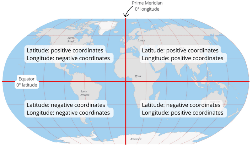
When you google for your city's location, Lat/Lon coordinates are usually expressed using degrees with an orientation identifier (N/S/W/E). To make adjustments easier, I use +/- sign according the above chart. For S and W use negative, for N and E use positive values and round to the next full degree.
E.g. a Google search for "lat lon Minneapolis" results in 44.9778° N, 93.2650° W. Adjust settings to "Lat 45" and "Lon -93".
To change settings, press the encoder button until a box appears at the current time display for the month, adjust by turning the encoder. Use a short press to advance to the next setting. Every change in settings triggers a full calculation so you can observe how Alt/Az values and the position of sun and moon are changing while making adjustments.
I added time zones for the US and the UK/European main land as well as plain UTC. I did not include a setting for the date format, this is always MM/DD/YY. Maybe adding this in a later version. Not sure if a time format matching the timezone or simply a universal format would work better.
If you like to add your own timezone, change the TZdata array. You can remove the ones you don't need or add as many you want to be listed. The array is dynamic and does not need any changes to references. The format of one entry is as follows:
The parameters from left to right:
- Display name: "Central" (just a text)
- String for switching SDT/DST, POSIX format (see below).
- Display text for standard time
- Display text for daylight saving time / summer time
The POSIX time format in short form is like this: Mm.n.d/time
- Mm: The month (1-12).
- n: The week number (1-5) (use 5 for last week).
- d: The day of the week (0 for Sunday, 6 for Saturday).
- time: The time in 24-hour format (e.g., 2:00:00, can be abbreviated).
I do hope that at some point this pesky DST switching will be obsolete, but I guess, there won't be an easy consensus... oh well. If this may still happen, you can still keep the time zones, simply remove the switch dates and define just the zone.
(Update: The version using the single larger display uses touch to adjust settings. Just use the stylus hitting the individual setting fields like H/M/S HH:MM and timezone or Lat/Lon. Once these have been touched, a settings field popping up in the display's center allows changing values +/- and return to normal. An example will be shown in the "Final Build" chapter)
Sample Sequence of Images


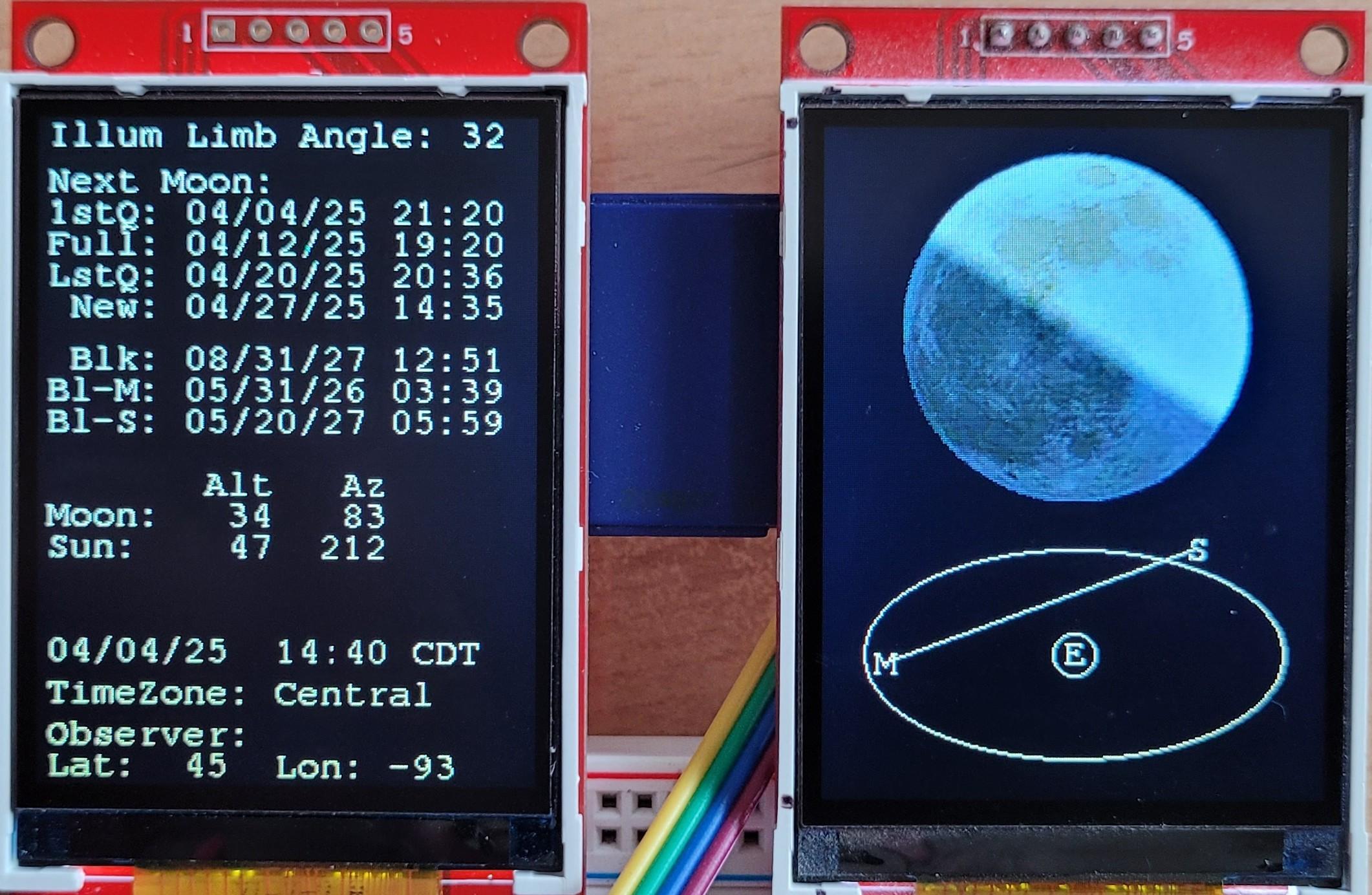


The images sequence starts at 11:39 Central time, briefly before the 1st Quarter moon at 21:20 (top of the list of next moon events). The bright limb is at 44°, counted CW from the top.
The upper part also showing the upcoming black/blue moon dates:
- Blk - black moon
- Bl-M - monthly blue moon
- Bl-S - seasonal blue moon
(Update: besides monthly black moon, I added seasonal black moon dates as well)
The position display below the moon does only show the Azimuth, not taking Altitude into account. At that time, the moon was just above the horizon (Alt 6°, probably not visible unless you'd be at a shore line) and rising ENE (Az 56°, East would be 90°, counting from north, CW). For folks on the northern hemisphere (Lat >= 0), the ellipsis is showing south on top. We are used to look south for sun and moon on their path.For folks on the southern half on this ball (Lat < 0), the ellipse is rotated 180° as they are looking north.
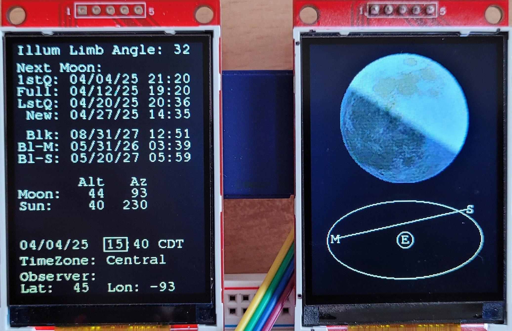
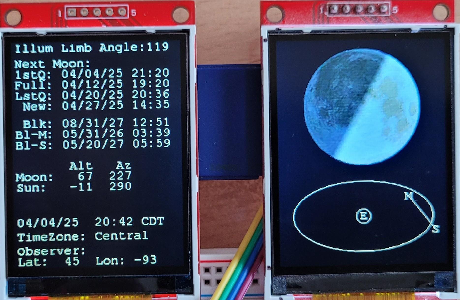
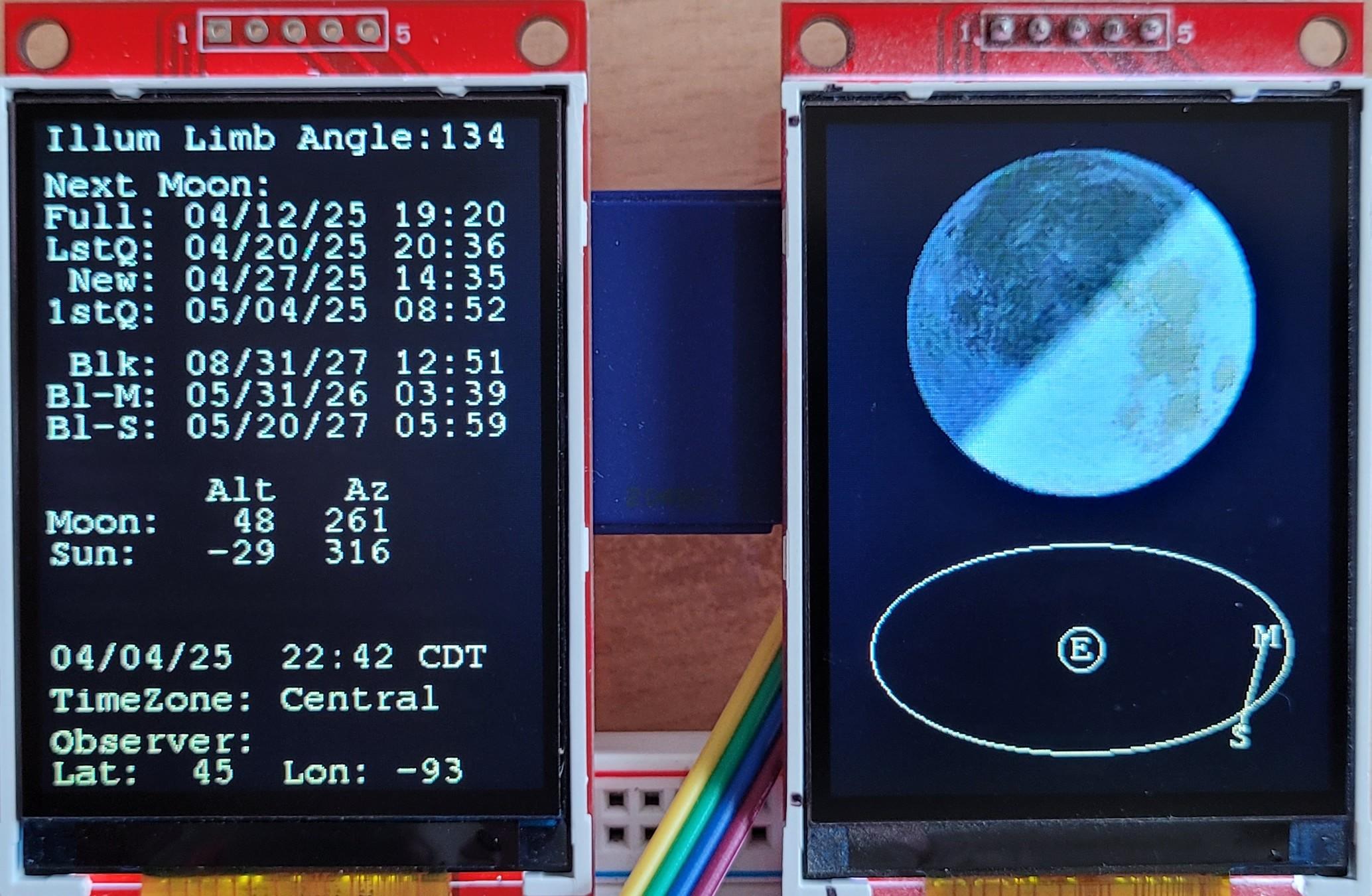
The screenshots are in one hour steps during the day and following night. At 14:40 the moon image changes to 1st Quarter. The illuminated limb angle has reduced to 32° and will start increasing again during the next hours. At 19:41, while the sun is setting, the limb's angle has increased to 93°. In the last image, short before midnight, the limb's angle is at 135° and will reduce until next day about 11am again. As everybody knows, this will shift over the moon's cycle of about 29.53 days.
During the sun or moon are below the horizon (Alt < 0°), the display will still show the moon, purposefully ignoring that the Earth is getting in the line of sight.
Of course there are times in which the limb's angle is somewhat irrelevant, new and full moon are special cases. The angle of the illuminated limb will still be calculated but will change very rapidly due to the small angles in the constellation of sun, moon and earth, almost being in line. If we want to be very precise (I mean actually hairsplitting nerdy) everybody knows that a real full moon can only be observed during a moon eclipse, when sun, earth and moon are in one line. Same is true for an exact new moon, which happens only during a solar eclipse.
One other thing needs to be noted when you explore various locations on earth. Settings allow you to go over Latitude 90 (north-pole) which will switch you to -90 (south-pole) causing a 180° flip. The same is true for Longitude above 180° rolling over to -180, but this does not cause a flip, because this is just going around the globe in the same direction.
Final Build


As mentioned above, I made a simple box to carry the two displays. Since this is a work in progress and I am not sure where this goes, I just needed a holder, easier to handle than a flying breadboard build.
Update: I added a case for the single-touch-screen which also has a place for the usual stylus included in the display. One is showing the setting display in action as well