Morse Master


Greetings everyone, and welcome back.
Morse code, a timeless art form, continues to be revered for its ingenuity and history. Imagine developing a device that bridges the gap between traditional communication methods and current technologies.
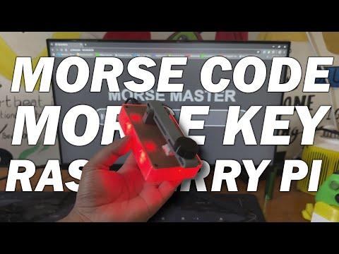
Meet Morse Master, a Morse Code translator that can be controlled with a sleek web app or a tactile push button. The Morse Master goes beyond utility by combining interactive LED displays, Wi-Fi connectivity, and manual input choices in a single attractive design.
This device is powered by the Raspberry Pi PICO W Dev Board, allowing us to connect it to the internet. We created a webapp that allows users to enter any message, which is subsequently translated and outputted via the four 5mm LEDs linked to the Raspberry Pi pico W.
Furthermore, we have included a mechanical switch on this device that allows us to manually enter the morse code.
We designed the 3D model of Morse master in Fusion 360, borrowing inspiration from real Morse Key devices used to type Morse code. The idea here was to create a device that could be easily 3D printed and assembled.
Using one of our previously designed Raspberry PI PICO Expansion board Circuit from a previous project, we used the custom board to create a simple Raspberry Pi PICO W and 5mm LED setup that would be used to display Morse code via RED LEDs.
This Instructable is about the build process of this Morse Master device, so let's get started with the build.
Supplies
These are the materials used in this build:
- Raspberry Pi PICO W
- Custom PICO Expansion Board PCB
- Header Pins
- 5mm RED LED
- 3D Printed Parts
- M2 Screws
- M3 Bolt
- DC Barrel Jack
MORSE CODE—History and Facts

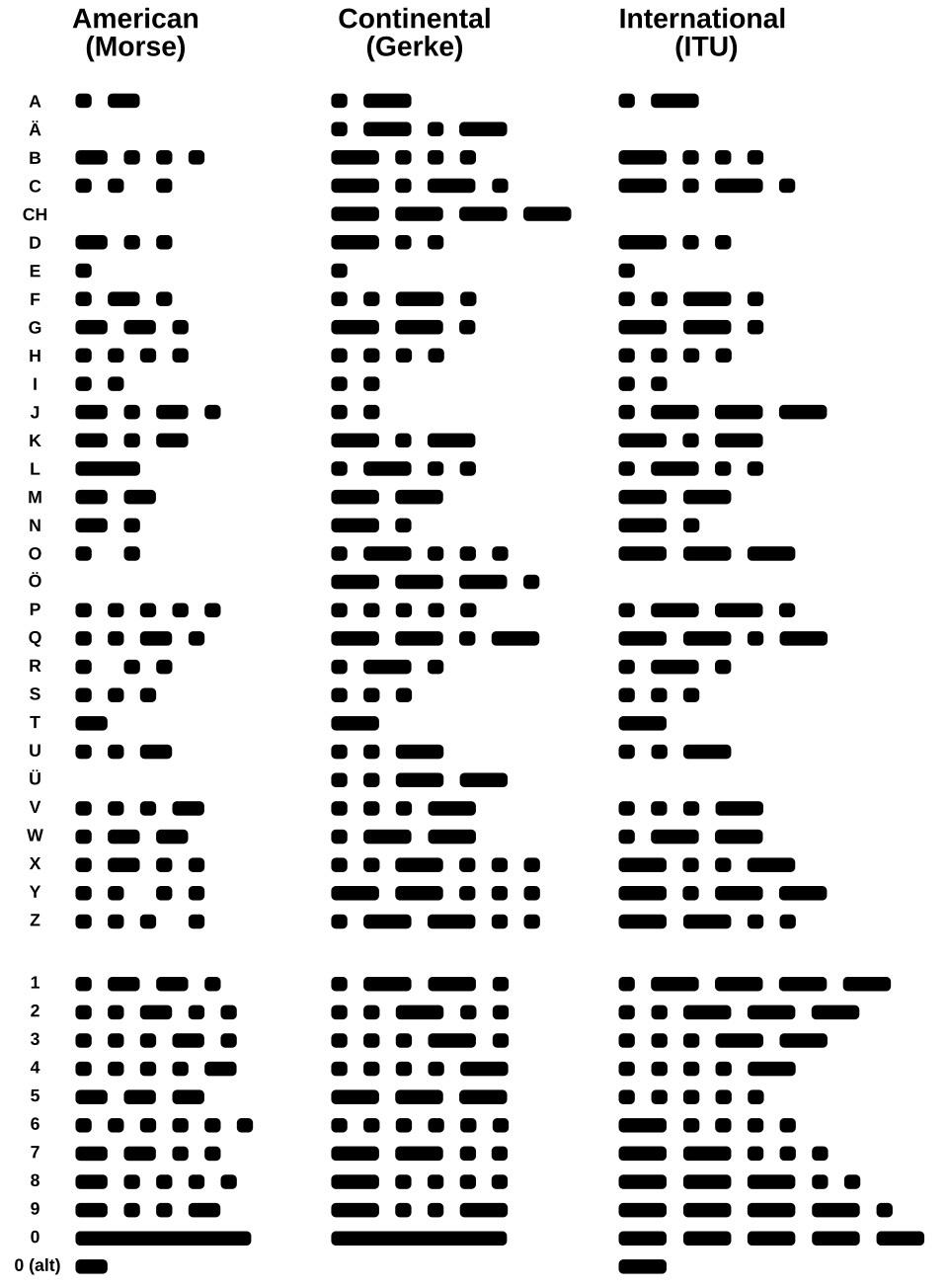

The Morse code was created in the early 1830s by Samuel Morse, an American artist and inventor, and his collaborator Alfred Vail. It was initially developed as a way to send communications over large distances using the telegraph, a revolutionary communication instrument at the time.
The first version, known as "American Morse Code," employed dots and dashes to represent letters, numerals, and punctuation.
In 1851, a more standardized form known as the "International Morse Code" was established to incorporate non-English characters and diacritical markings, making it appropriate for global use. This form became the universal norm, and it is still acknowledged today.
The Morse key, also referred to as a telegraph key, was a device for manually transmitting Morse code signals via telegraph lines. It consisted of a lever that could be depressed to complete an electrical circuit, letting current to flow and provide a signal. Operators would press the key to create short signals (dots) and hold it down for long signals (dashes). These messages were sent as electrical pulses across telegraph cables to a receiver, where they were decoded into letters, numbers, and symbols.
The Morse key required aptitude and precision since operators had to keep consistent timing for dots, dashes, and gaps between characters and sentences. Experienced telegraphers may convey messages at astounding rates, generally measured in words per minute. The device was widely employed in communication systems, particularly in railways, maritime operations, and military settings, where it played an important role in transmitting critical information rapidly and reliably. Over time, the Morse key came to represent early telecommunications and the era's innovation.
DESIGN


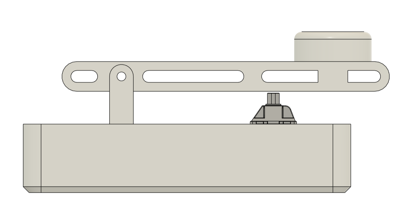
We modeled our design after the Morse key, creating an enclosure that holds the Pico W circuit within; this comprises of a main body and a lid, to which we have attached a lever holder.
We included a lever alongside the Lever holder, and on one side of the lever, we included a knob similar to the one found on a Morse key, which allows the user to correctly grip the lever and operate the device.
A mechanical Blue Switch has been added to the Lid part, and the Lever is positioned above the Mechanical Switch; when the lever is pressed down, the switch toggles, and a switch press is registered by the PICO W.
To hold the mechanical switch in place, we built a square opening to the lid; the mechanical switch slides into this slot and is kept in place with two locks on its body. These two locks enabled us to securely hold the switch in place on the lid section.
The circuit is mounted inside the main body and held in place with four M2 screws, each with its own screw boss.
Regarding the design of the lid section and main body assembly, we have added four screw holes in each corner, as well as four screw bosses next to each screw hole. We'll be using four M2 screws here as well.
To secure the lever to the lever holder, we just use a Long 30mm M3 Bolt.
Our design follows the design language of prior Morse Keys that have been used in the past.
We printed the main body with transparent PLA to diffuse the red color glow. The lid part was printed with brown PLA, the lever and lever holder were printed with grey PLA, and the knob was printed with black PLA.
PCBWAY SERVICE

Let's have a look at the Expansion Board PCB which was designed from scratch and then sent to PCBWAY for samples.
Expansion board order was placed for White Soldermask and Black silkscreen.
After placing the order, the PCBs were received within a week, and the PCB quality was pretty great.
Their commitment to quality and customer satisfaction has been unwavering, leading to significant growth and expansion.
Also, PCBWAY is organizing a PCB badge-making competition to mark their 11th anniversary, inviting designers and makers to showcase their creativity by designing badges that celebrate the company's legacy and envision a bold future. Participants must incorporate the elements "PCBWay" and the number "11" in their designs and can use PCB, PCB+SMT/THT, or PCB+3D printing techniques. Submissions can be posted in the comments, emailed, or shared on social media with the hashtag #PCBWay11BadgeContest.
Prizes include cash, PCBway coupons, and free prototyping services for all qualifying entries.
You guys can check out PCBWAY if you want great PCB service at an affordable rate.
RASPBERRY PI PICO W SETUP


The Raspberry Pi Pico W, a compact and versatile microcontroller that adds wireless connectivity to the already popular Pico series, will be used as the project's brain. It is powered by the Raspberry Pi's RP2040 chip and has a dual-core Arm Cortex-M0+ processor that can run at up to 133 MHz, making it both efficient and powerful for a variety of applications. This microcontroller, which includes built-in 2.4 GHz Wi-Fi, was ideal for our Morse Code Translator devices project, that utilizes a WEB APP.
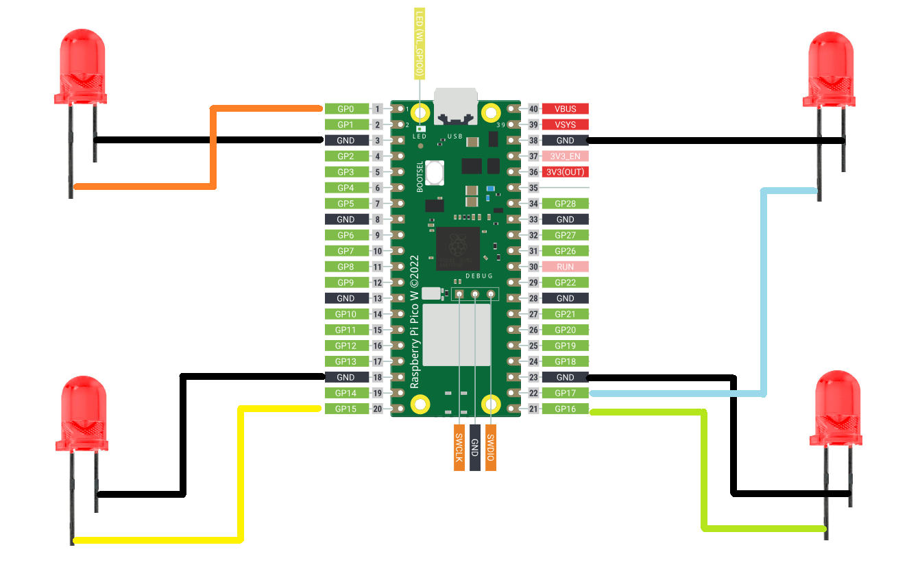
We coupled the PICO W with our previously created PICO Expansion board, which breaks out all of PICO's GPIO pins and adds extra pins that may be used to pair sensors and other electronic devices with PICO. In our case, we added four 5mm RED LEDs to PICO W's GPIO pins.
The anode of the LEDs is linked to GPIO0, GPIO15, GPIO16, and GPIO17, while the cathode of all LEDs is connected in parallel and then coupled with the GND of PICO W.
BOARD ASSEMBLY


- The board assembly process begins with the installation of two CON20 Female header pin connectors in place of PICO W. We will use these header pin connectors in place of PICO.
- Next, we place four 5mm LEDs near each corner of the expansion board.
- By flipping the board over, we use a soldering iron to solder each through-hole pad, securing all THT components in place.
- Using pliers, we align the excess legs of a 5mm LED and attach them to the PICO GPIO pins. We built connections and linked all of the LED anode pins to GPIO0, GPIO15, GPIO16, and GPIO17. The cathode of all LEDs is linked to GND.
- After finishing the soldering, we installed PICO W over the CON20 header pin connector.
TEST SKETCH


For testing the LEDs, we uploaded a Sample Chaser sketch to our PICO W, which turns ON and OFF each LED in a Chaser Sequence in a Loop.
After making sure that our Setup is working electrically, lets move to the assembly process.
BUTTON ASSEMBLY


- We place the mechanical switch in its slot on the lid section, pushing it downwards to secure it in place.
- Next, we solder wires from GPIO1 to one terminal of the switch, while the other terminal is linked to the GND terminal.
DC JACK ASSEMBLY


DC barrel The jack is then inserted in its mounting hole on one face of the main body and fastened in place with its nut.
BASE BODY & LID ASSEMBLY


- The PICO W Circuit is then installed within the Main body, over four screw bosses, and tightened with four M2 screws.
- Next, we connected two wires to the PICO's VBUS and GND terminals, then connected the VBUS wire to the DC jack's VCC and the GND wire to the DC jack's ground.
- We then install the lever holder on top of the lid by aligning the mounting holes and secure both of them with two m2 screws.
- The Lid Part is then installed from the top side of the Main Body, and four m2 screws are used to attach both of them together.
LEVER ASSEMBLY

For the Lever Assembly, we placed the 3D Printed Knob over the lever and secured it with an M2 screw.
FINAL ASSEMBLY


- For the final assembly, the lever is attached to the lever-holding part, and a Long M3 Bolt is utilized to connect them both.
- We tighten the M3 bolt with a secure driver, and the assembly is now complete.
MAIN CODE
Here's the code used in this build and it's a simple one.
We first added the required WiFi.h and WebServer.h library which enable the Raspberry Pi Pico W to connect to a Wi-Fi network and serve a webpage for remote control of the device.
Replace these with your Wi-Fi network's SSID and password. This allows the device to connect to your network and function as a web server.
Hardware Setup
GPIO pins connected to four LEDs. The LEDs will blink together to represent Morse code signals. GPIO pin connected to a push button, which allows users to manually input Morse code.
These constants define the timings for Morse code signals-
A dot is shorter than a dash and Pauses between symbols, words, and button press detection are precisely timed.
Morse Code Translator
Converts a character into its Morse code representation (e.g., "A" becomes ".-")
Handles letters and spaces; unsupported characters are ignored
LED Control
initializeLEDs(): Sets up the LEDs as output and ensures they are initially ON.
setLEDState(bool state): Controls all LEDs at once, turning them ON or OFF.
Manual Button Input
This Detects button presses and determines whether the user is inputting a dot or a dash based on how long the button is held.
The LEDs provide immediate visual feedback during and after a button press.
Blink Morse Code
This Controls the LEDs to blink according to the provided Morse code sequence.
Dots, dashes, and pauses are visually represented using precise durations.
Remote Control via Web Server
handleRoot(): Displays a simple web interface where users can submit text messages for translation.
handleSend(): Processes the submitted message, translates it to Morse code, and blinks the LEDs.
Display Morse Code
This Converts a full text message into Morse code and uses LEDs to display it.
Setup Function
This Initializes LEDs, button, Wi-Fi, and the web server.
Main Loop
This Continuously processes web server requests and monitors button presses for manual Morse input.
After uploading the sketch, the IP address for the Web app is obtained via Serial Monitor.
POWER SOURCE

For the power source, we will use a 5V power bank, and to connect the power bank's 5V to our device, we will use a modified USB cable. One end of the cable will have a regular USB port, and the other end will have a barrel jack connector with 5V of USB linked with the barrel jack's 5V and GND to ground.
RESULT


The ultimate result of this Build is a Functional Morse Code Translator device that can be operated via a web app or by using the onboard Key Mechanism to input Morse code, which will be displayed via the LED.
Using this device, one can access the webpage and translate whatever message he wants by entering the message into the Enter Message Bar and then clicking the Submit button, which will start the translation process. The LED blinks in response to each letter in Morse code.
MORSE CODE TRANSLATION


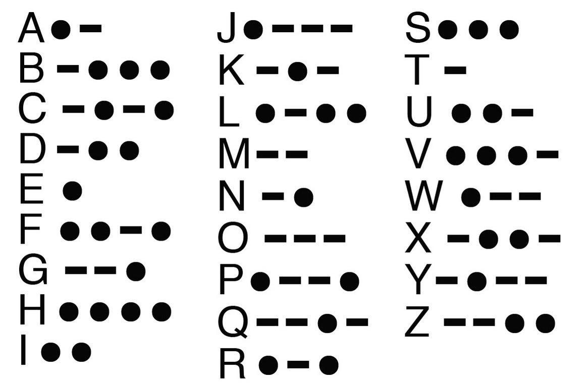
Let's have a look at some of the alphabets we attempted inputting into the website. We'll start with the letter A, which is represented by a dot followed by a dash. In our case, a short Blink (dot) is immediately followed by a longer Blink (dash).
Next, we tried Letter B, which is represented by a dash followed by three dots. In our example, it begins with a longer Blink (dash), followed by three short Blinks (dots) in rapid succession.
We then entered Letter C, which consists of a dash, a dot, another dash, and a final dot. In our case, the sequence would be a long blink (dash), a short blink (dot), another long blink (dash), and finally a short blink (dot).
After mastering the code, we were able to pronounce HI in Morse code, which consists of H (four rapid blinks) followed by I (two quick blinks), with tiny intervals between each blink and a somewhat longer break between the two letters.
This device allows you to translate sentences, characters, and alphabets into Morse code by accessing the WEB PAGE or manually entering the Morse code using the onboard Morse key configuration.
Please let me know if you require any additional assistance; all the documents, files, and code are included in the article.
Thanks for reaching this far, and I will be back with a new project pretty soon.
Peace.