Mouse the Self-driving Robot
by Art3mispie in Circuits > Robots
2731 Views, 16 Favorites, 0 Comments
Mouse the Self-driving Robot


Mouse is a simple maze solving robot to teach students and young engineers about robotics and the use of a micro-controllers.
The robot uses a Micro:bit connected to a Kitronic motor diver board and an ultra-sonic sensor to find information and make a decision as a result.
This project is designed with a simple and easy to understand program that allows the robot to drive itself and turn when it detects an object in its path.
While creating this project I designed it so that the idea of the vehicle is easily changeable without having to change the hardware.
I hope that anyone recreating this project will expand on my program and come up with new functionality. Other features that I tried was add RC features with the addition of a second Micro:bit that is used as the control panel and can send, receive and display data to the robot.
Supplies
Electronics:
- MicroBit V1 or V2
- Kitronik Motor Driver Board V2
- 2x Right Angle Geared Motor
- Ultrasonic Distance Sensor HC-SR04
- Wires
- Battery Pack
Other Supplies:
Tools:
- Utility Knife
- Hot Glue Gun
- Screwdriver
- Soldering Iron
- 3D printer (optional)
- Laser Cutter (optional)
Create a Base

- I designed a base that would have enough room for all the components and left space to the sides of were the motors would go, this is for the wheels.
- When designing the base it is important to keep in mind the position of where the wheels will be, in this case I used two wheels so I made sure to keep them in the front of the robot.
- I measured and drew out the design on a thick piece of cardboard
- I cut out the shape with a box cutter and cleaned the edges with a pair of scissors.
- To finish I covered all the sides in black electrical tape to hide any rough edges.
Below I left a 3-D model of the base that can also be 3-D printed or laser cut.
Put in Components


- I set out the motors and the driver board first, these were some of the biggest and most important parts.
- I used double sided foam tape to stick down the motor driver board and hot glue for the motors. I find double sided foam tape is perfect for sticking down all types of PCB's as it sticks well, non-permanent and cushions the connections of solder on the underside.
- Next I used hot glue to glue down the ultrasonic sensor with the pins facing upwards.This allows for easier wiring that can be accessed if needed at a later time.
- Lastly I added a dot of hot glue to the motor connections for the wheels and put one wheel on both sides.
Wiring!


- I took a battery snap and screwed each wire to its matching place in the terminal ports on in the power section on the right side of the board.
- I ran two wires from each motor into the terminals MOTOR1 (m1) and MOTOR2 (m2), m1 being the right side motor and m2 being the left side, it does not matter with side the two wires go as it can be easily changed in the code later on.
- I added a small dot of solder to all of the connections on the motors to make sure no wires came loose.
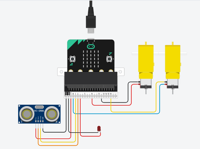
- I soldered a wire to each of the four pins on the ultrasonic sensor. Then I connected these wires to the pins on the back, gnd to GND, vcc to 3V. For the input and outputs I used the front terminals, echo INPUT1, P1 and trig to INPUT2, P2.
Coding the Ultrasonic Sensor


The sensor should be wired as shown:
- VCC 5v
- GND GND
- Trig P2
- Echo P1
- I initialise the variable were we are going to store the data from the readings of the sensor.
- I send a signal to the trigger pin telling it to play for 10μs then stop.
- I finally tell the code to read how long (in μs) P1 is getting a signal, divide my 36 (which I found to give the distance in cm) and write that number to are variable "dis".
Coding


Now we have to code the mirco:bit.
If you do not know how to write code to a micro:bit I have linked an article: Coding via PC or Coding via iOS / Android
- You have to import the library, go to the settings icon, click on 'Extensions' and search for 'kitronik-motor-driver', it will be the first one.
- You use this library to control the motors, you can set the speed, direction and stop them from this tab.
- You then use conditionals to control each motor turning when needed based on the data from the 'dis' variable.
Testing


- Does it work?
- What can you change?
- Can you make it better?
See what other ideas you can come up based on this project.