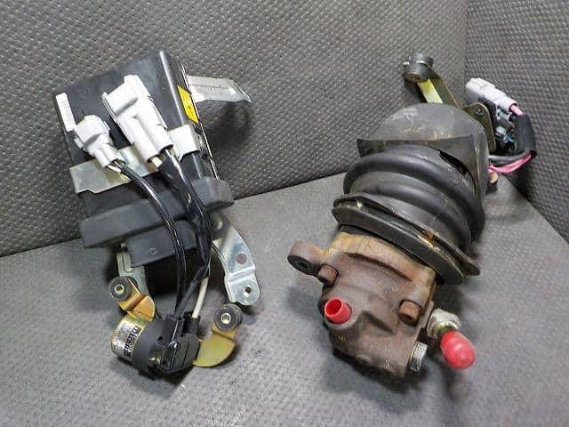
Mr2 Sw20 Power Steering ECU Reverse Engineering
140 Views, 1 Favorites, 0 Comments
Mr2 Sw20 Power Steering ECU Reverse Engineering

This guide will also help those who are trying to transplat the sw20 ps system to a project car and expecting it to behave just like how it was from the factory, alternatively opting for an after market controller from aliexpress.
If your Toyota MR2 SW20 has stopped assisting your steering and the Power Steering (PS) warning light is on, chances are you’ve encountered Error Code 13 — a fault related to the MTH (torque sensor) signal from the power steering motor.
This is one of the most common issues owners face when restoring or troubleshooting the MR2’s electronic power steering system. Over the years, heat, vibration, and age can degrade the wiring harness, causing the MTH signal to float, short, or read incorrectly at the ECU. When this happens, the ECU immediately disables the power steering motor for safety.
In this guide, I’ll walk you through how the MTH signal works, how to test and diagnose wiring issues, and how a simple 10 kΩ series resistor placed in the right spot can help protect your ECU and verify whether the problem lies in the harness or sensor.
Supplies


- Many thanks to shinny who have outlined the solution here.
- Link to the service manual gen 1
- After market 100amp motor controller from Aliexpress
- Wiring diagram and fault code retrieval attached
PS ECU


Terminal Function How it works / Notes
WL
Warning Lamp
Sends a signal to illuminate the PS warning light on the dash when a fault occurs by pulling low (e.g., torque sensor fault, code 13).
SS1 / SS2
Steering Sensors (likely angle or torque sensing inputs)
Read from sensors to determine steering input and load. Works with MTH to calculate required motor assist, operating at 5v range.
SPD
Vehicle Speed Input
Receives speed info from the speed sensor. ECU adjusts power assist based on speed — less assist at higher speeds operating at 5v range.
IGB
Ignition +B (12–13 V supply)
Powers the ECU and sends voltage to the motor relay circuit. Typically hot with ignition ON.
CHK
Diagnostic / Self-check
Used during ECU self-test routines; may pull low to enter diagnostic mode outputting error code via WL.
IDUP
Idling status
Engine ECU
EFI
Engine ECU PSCT control logic
Switching off the power steering ECU in an emergency by pulling low.
MRLY
Motor Relay Control
Outputs a ground or positive signal to energize the power steering motor relay, which connects +B to the motor positive terminal.
BMS
Brush wear / motor monitor
Monitors motor brush status; sends signal back to ECU if brushes are worn or voltage anomalies detected.
MTH
Torque sensor output (red wire)
Measures voltage applied to ps motor. Voltage ranges from 13 V (minimal torque) down to 2 V (maximum torque) at the motor end. ECU reads this feedback to confirm the motor is doing what is meant to be doing giving the correct assist. There is a possibility mis-match may be due to the different model years or electrical noise where resistors may be needed.
PS Driver

| Terminal | Function | Notes |
|---|---|---|
| IFB | Feedback from driver module | Sends back motor current or status info to ECU. ECU uses this to adjust assist. |
| IOVR | Overcurrent / protection input | Monitors if the driver module or motor current exceeds safe limits. Can trigger ECU to shut off assist. |
| ICTR | Control signal to driver | Likely controls motor current or PWM duty cycle for assist. |
| ISTP | Stop signal / interlock | Prevents motor operation in certain unsafe conditions. |
| SGND | Signal ground | Provides low-noise ground reference for ECU-to-driver signals. |
PS Motor

Motor terminals
- Positive terminal (+) → Connected to motor relay controlled by MRLY from ECU. Relay closes → motor gets +13 V.
- Negative terminal (−) → Connected to driver module; driver module switches to ground as required to control motor current (PWM or direct drive).
This design allows the ECU to control motor current precisely, while using the relay for high-current connection to +B.
Torque sensor (MTH) wiring
- Red wire, MTH → Signal to ECU.
- Voltage behavior:
- Minimal torque (wheel at rest / free) → ~13 V
- Maximum torque (hard turn) → ~2 V
- Purpose: ECU reads this analog voltage and calculates how much power assist the motor should provide.
- Any wiring issues (open, short, corrosion) will cause abnormal readings → ECU sets code 13 → PS warning light ON, it may also be caused by a mismatch ECU where 5v signal is expected.
Motor Bushes sensor (BMS) wiring
- Supplying voltage/current to the motor brushes.
- Monitoring brush wear or motor load indirectly by measuring brush voltage/current.
If the brushes wear out or the connection is poor, the ECU may detect abnormal current and trigger a warning (like a PS warning light).
How Everything Work Together
How the system works together
- Driver applies torque → MTH sensor outputs voltage proportional to torque.
- ECU reads torque voltage (MTH), steering sensor signals (SS1/SS2), and vehicle speed (SPD).
- ECU calculates how much motor assist is needed.
- ECU sends control signals to driver module (ICTR, ISTP) to modulate motor current.
- Motor positive powered via relay (MRLY), motor negative switched by driver module.
- Feedback signals (IFB) allow ECU to monitor actual motor behavior and adjust as necessary.
- ECU reads motor bushes voltage (BMS) indicating if they are worm and need replacing.
- Any anomaly in sensor signals, motor current, or wiring → ECU sets fault (code 13, etc.), illuminates WL, set MRLY negative.
- ECU will output code 11 if torque voltage is not detected