Multi Purpose Rotary Machine - Mulling, Welding, Pottery, Photography Turntable
by bongodrummer in Workshop > Metalworking
23039 Views, 168 Favorites, 0 Comments
Multi Purpose Rotary Machine - Mulling, Welding, Pottery, Photography Turntable

Welcome Friend!
We are going to make an upcycled multi purpose rotary machine. Something that has a large platter, that can turn at an adjustable, yet reliable and consistent speed. We will be using a old an washing machine for the motor and frame, a scrap microwave gives us an electronic timer, and other junk makes up the rest.
This instructable is quite big! Maybe I should have made it three or four separate ones - it contains details of how to wire and implement a few different methods for speed control of old washing machine motors (useful for any number of projects), through to rotary welding, green sand mulling, upcycled microwave timers, etc etc).
You could mosey through from the beginning to end, seeing how I built the whole machine, or you might rather skip to sections that are most appropriate for you. For that reason, hears a little quick-reference contents for you:
Steps 1-4 Dismantling stuff for upcycling
Step 5-9 General machine structure
Steps 10-13 The spinning platter
Steps 14-21 Re-using a series wound, washing machine motor, basic speed control & closed loop control with Arduino.
Steps 27-30 More mechanical speed reduction and why we need it (pulley talk)
Step 31-34 Microwave timer (a simple timing solution that would work for many projects
Step 35-36 Rotational photography - 360 degree shots
Step 37-44 Mulling machine details, (somewhat in process)
Steps xxx Rotary welding table & pottery wheel (very much in process)
Find Your Parts- Material Based Design


This step is where I encourage you to reuse junk that's broken for your projects. Material based design, as I call it, starts with taking stock of what 'rubbish' you have easily available, thinking about what you want your project to achieve, and tying the two together. 3D modelling and CAD is great, and I'm a big fan, but I am not so keen on the tendency to design in abstraction from the materials, and then use a prime fresh (and often expensive) material to make said design. Therefore I am a big advocate for having an intimate connection with the materials you plan to use (and an awareness of where they are coming from, environmental costs, etc.).
Getting tactile and hands on makes you a better designer, even if you mainly model in CAD. At least that's what I reckon. And a super bonus to upcycling is that as you take stuff apart, you get an in depth knowledge of how other people designed stuff in the past!
For this workshop tool, we are wanting a spinning action, and, like many people, I had an old washing machine laying about. It leaked but the main bearing and the motor was good, ... Perfect.
Lets dismantle and see what we can use.
Dismantle the Washing Machine


Undo the outer screws, and pull things apart. We are looking to take out the main drum (be ready to catch the water or do this outside!), salvage the bearings, spider, drum, frame, wiring loom, drive belt, motor and some of the control board components. Oh and for this one we are going to use the steel body of the machine too.
Once you take the drive pulley off the spindle, you should be able to push the shaft out of the bearings. This might need some persuasion with a hammer - protect the end of the shaft with a scrap of wood or the hammer may 'miss-shape' it and the drive pulley won't go back on nice.
Take Stock of Your Free Stuff!


Yep there's plenty of goodies in them scrap washing machines. Mains water pressure rated solenoid valves, heating elements, a nice stainless steel drum, a pirex glass bowl, mains power water pump, even a bunch of nice coach screws (these held the two halves of the plastic drum together)!
Dismantle the Microwave (Collecting a Ready Made Timer)


It will be nice to have a timer turn the machine off after say 2 minutes, when it is being used to mull green casting sand. A microwave timer is great for this - as well as many other projects! It has a ready made electric timer that controls a relay. It even has a clear display showing the remaining time...
Butcher and Refresh Your Machine Frame


The frame of my washing machine was a bit rusty and very grubby (it had been outside for some time). If you do a project like this I recommend acquiring a machine that is in better condition. I went with what I had though, which meant cleaning (pressure washing :P and wire brushing the rust off.
I want to use the inside for storage - I'll probably put shelves in - so instead of the small round port-hole, I used an angle grinder and slitting disc to cut a square opening in the front (that's approximately the size of an old scrap kitchen cupboard door I have)...
The edges of the cut were sanded smooth to prevent accidents, and all the bare metal was touched up with metal paint.
The Bearings Removal and Prep


The bearings are encased in the big plastic washer drum, and after rudely hacking them out with the jigsaw, I used the bandsaw and then the lathe to make a cylindrical part that would fit nicely into a 'holesaw sized' hole.
This would be perfectly possible without a bandsaw or lathe, it would just take a bit longer to use a handsaw and files to cut it out...
Making the Top


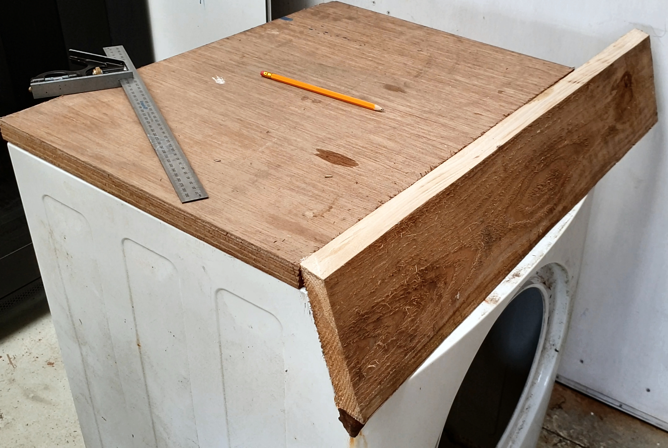
The original top of this washing machine was a bit too broken to use. It was made from plastic laminated onto chipboard which had got damp and surrendered to the resultant softening effect.
Luckily I had a scrap of nice ply I recently fished from a skip. I don't know what kind it is but it seems like some darker wood and is over 1" thick, so will do nicely. None of the edges are straight, looking to have been cut with a jigsaw to fit round a wiggly wall. The circular saw with a guide works wonders to square up this kind of thing, that would be a bit of a handful to push through the tablesaw.
Bearing Undercarriage


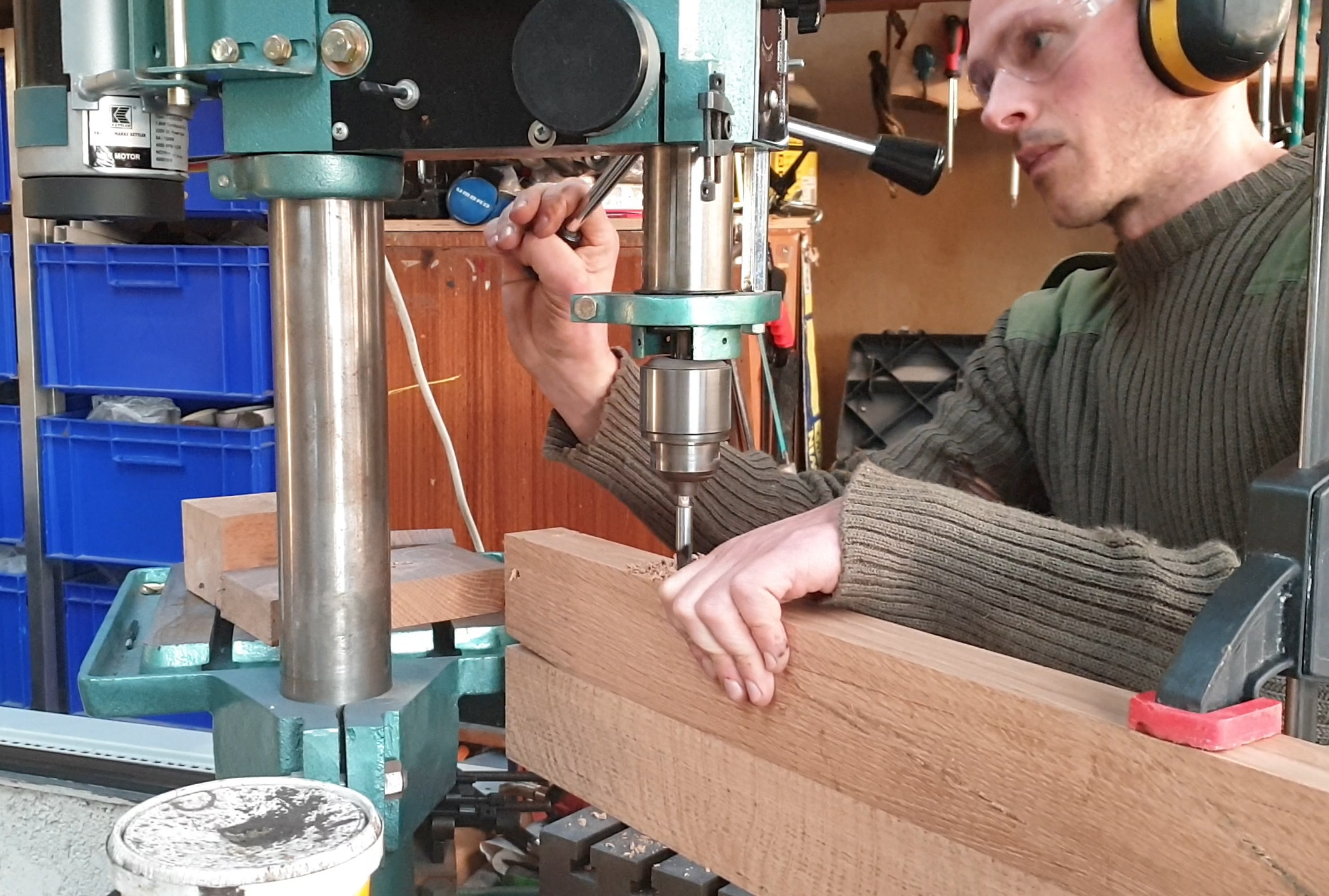


Adding the plywood top helped to stiffen up the whole structure, but I still wanted a bit more security for the bearing mount so I added some oak hardwood I had chainsaw milled (check out my CS Mill I'ble) some years back. It was dense, strong and hard, so should work well.
I ripped it in half on the bandsaw, and used some reclaimed engine bolts that were nice and long to clamp the halves together. Then the holesaw created the opening to receive the bearing block. Loosening the bolts allows me to slide the bearing block in, tightening them up locks the bearings in place. Check the picture notes for more details...
Fixing the Top


I cut a few wooden spacers so the lid fit to the uneven curves of the sheet metal washing machine frame.
A bit of fiddling about had it nice and square, firm and level, and ready to be screwed in place.
The Spinning Platter #1 - the Spider Mount


The aluminium washing machine 'spider' needs to be removed from the drum. My one was riveted on, so needed drilling to remove. Once off its clear that this particular one is going to need a recess to fit flush with the underside of the platter we are making.
The Spinning Platter #2 - Laminating Scraps for the Turntable


The remains of the ply I used for the lid and some shuttering ply is cut into circles. I got this shuttering ply from a company near us that uses it to produce packing crates for shipping. They have reasonably big 3 x 2.5ft 'off-cuts' they can't use :D
It's not great quality stuff, but when laminated together, defects in individual sheets cancel out and it's really strong!
The Spinning Platter #3 - Gluing Up


To make for a stronger glue up I give the faces of the plywood a quick once over with the sander. I found what was the 'best' face, and designated that as the 'top' of the platter.
On the other joining faces, glue was spread evenly, leaving no patches uncovered. Then the whole thing is clamped up.
Attaching the Speed Reduction Pulley


Washing machine motors are designed to run at high speeds (more on that later), so we need to use the large pulley that fit on the spider shaft. The pulley is dished and would snag on the undercarriage if used as designed, so we need to mount the other way round. Being aluminium it is easy enough to cut or file the rectangular keyway all the way through so this is possible.
Using a Washing Machine Motor (Series Wound or 'Universal' Motor)


There are plenty of other kinds of motor types that could be used for this project, some would probably be better choices, but since I am in charge here, and I have (and you should be able to get your hands on) a spare washing machine motor or two - that's what we are talking about.
A theoretical, loss free series-wound motor, supplied at constant voltage has the characteristic of slowing down when load is applied at the following rate: The shaft speed halves, for every quadrupling of the load. Think about that a moment, it becomes important!
Implications:
1. The speed goes down (quite a bit), and varies depending on load - that's a pain if we want constant rpm, while we are mixing sand, rotating a welding workpiece or manipulating clay, for example.
2. If we have no load at all on the shaft the speed would rise - without a theoretical limit! In actuality on large high speed motors like washing machine motors, the limit can be the rotating armature having its ass kicked by centrifugal forces, and coming apart (bad - see warning below).
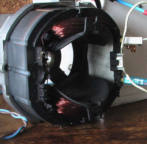
Identify the connections
Armature (between the brushes) should be easy - two connections and roughly 2 ohms. The value will vary slightly depending on how the brushes are sitting on the armature, so rotating the motor shaft slowly will likely change the value.
Series field winding ~ 2 ohms
AC Tachometer ~ 180 ohms
Over-temperature protection 2 contacts ( often read 0 Ohms, but depends)
The motor frame earthing point
Test the motor with a 12V bench power supply (briefly). Or by putting a 1kw heating element in parallel with the armature (see diagram).
Warning: do not connect the motor unloaded to its rated voltage. It probably won't survive, and in worst cases could fling shrapnel at you.
Motor Control #1 - Why?


In the previous step we learned that without a load this kind of series wound universal motor will go crazy fast and tear itself to pieces. To make matters worse with a load it will slow down annoyingly. What we need is speed control, and there are a few different methods.
Using the simple triac circuit shown in the next step.
Buying and using a pre-made motor controller,
Make and understand a proportional–integral–derivative (PID) motor controller (here's a primer on the subject) using a micro controller like Arduino in consort with a triac based circuit. This is the route we take here.
https://www.hackster.io/saulius-bandzevicius/ardui...
A useful little doc for motor identification - http://ala-paavola.fi/jaakko/lib/exe/fetch.php?med...
https://www.researchgate.net/publication/251886995...
Another good explanation of PID motor control. http://ala-paavola.fi/jaakko/doku.php?id=beer
Motor Control #2: the Simple Way
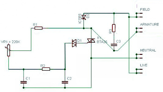
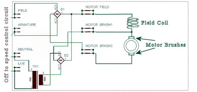
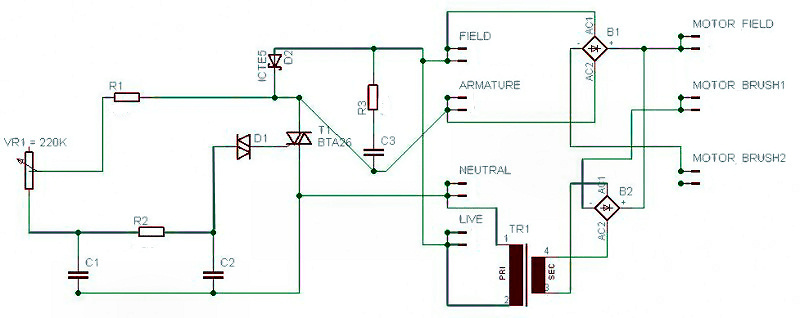
These are some simple universal motor control circuits that I have made in the past. They are based about a power triac (T1) that is triggered by a diac (D1). This kind of circuit is simple and time proven. Historically versions of this circuit have been used to control many different universal motors, from circular saws to vacuum cleaners.
I have used these circuits in the past on my lathe instructable here, so I'm not going to go re-hash that info in much detail here (check out steps 2 to 6 on that I'ble) .
The first schematic shows the most basic of these circuits, the second and third add in a rectified, low voltage, high current stage, that gives the motor much better speed holding under loads (it won't slow down so much when you put load on the motor).
This documents some further Improvements to this circuit, using a smaller triac to trigger the main one: http://educypedia.karadimov.info/library/CD0000385...
There is a lot to be said for the simplicity of this circuit, and if I was doing this project over, I might consider doing another one of these Vs the closed loop arduino version I made.
Motor Control #3 - Closed Loop Feedback

The speed control circuit I built is loosely based round one built by Saulius Bandzevičius - I have included a pdf of his schematic in this step, but also check out his write up here. It uses Arduino and the PID Library created by Brett Beauregard.
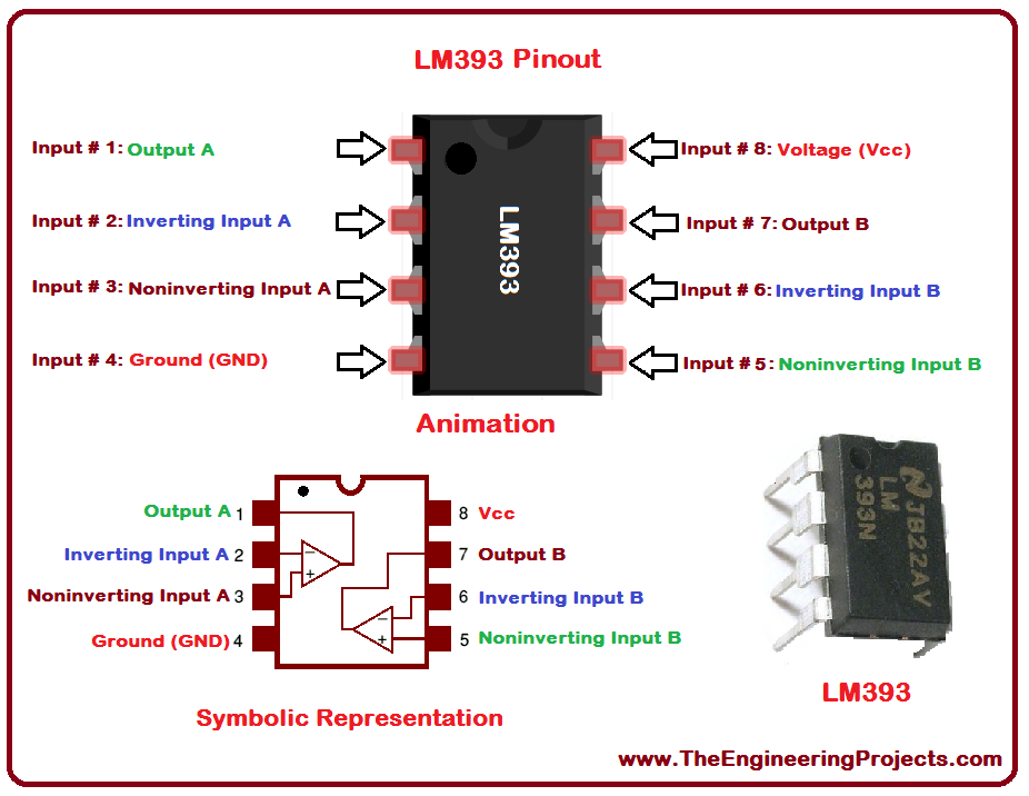
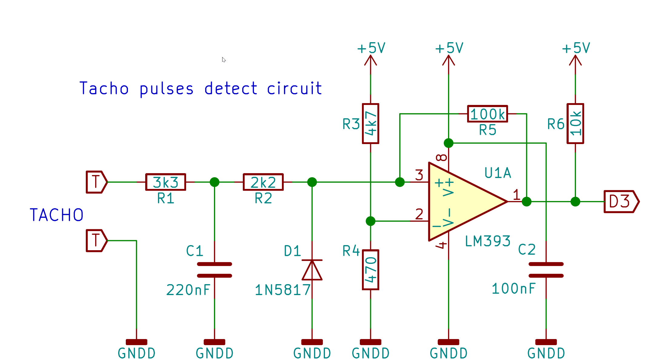
The basic principal of this closed loop system is that the Arduino takes in the AC signal from the motor's tachometer (conditioned through the LM393 chip - pinout above), to determine the actual speed of the motor and compares that against the 'set speed' - the RPM you want the motor to be spinning. It then uses a PID algorithm to determine when to send control pulses to an optocoupled triac, which in turn activates and allows pulses of mains voltage to the motor...
Motor Control #4 - Zero Cross Detection

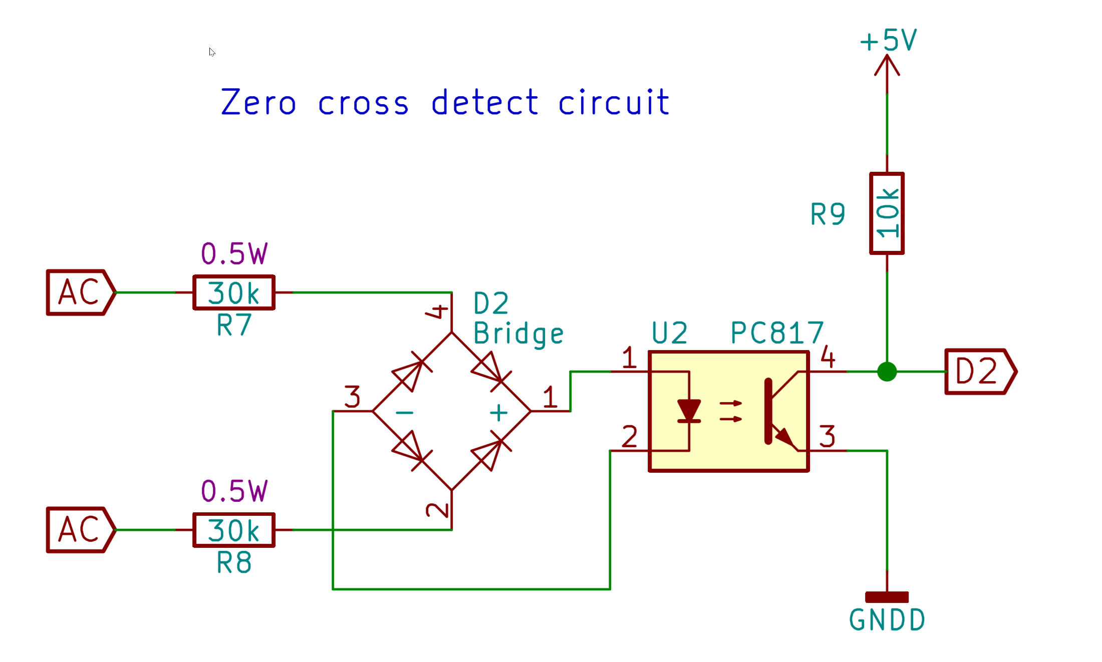

Mains AC is a sinusoidal waveform and the the Arduino needs to know the point at which the AC voltage crosses through 0V - the 'zero crossing'. The Arduino needs to know this to properly time when to trigger the triac’s firing action.
This document describes a simple zero cross circuit and why we want one: http://ala-paavola.fi/jaakko/lib/exe/fetch.php?med...
In the circuit I made we use a cheap little PC816 optocoupler to isolate the arduino from the mains voltage, which is a somewhat safer method than that used above.
Downloads
Motor Control #5 - Triac Triggering, Snubber Circuit and Transients
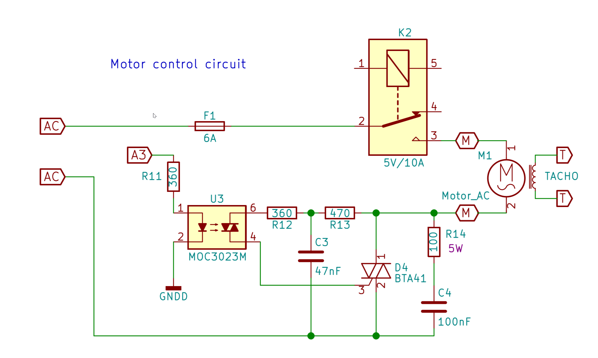
To trigger the power triac (the BTA16) we use an MOC3023M optocoupler connected to pin A3 of the Arduino. The optocoupler isolates the relatively fragile 5V Arduino microcontroller, from the mains voltage triac.
Transients are basically voltage spikes cause by inductive loads like motors. They can play havoc and cause unwanted triggering of the triac - essentially leading to choppy unpredictable motor running.
The snubber circuit 'snubs' the transients. It consists of resistor R14 and capacitor C4. I also added a 400V varistor in parallel with R14 and C4 (not shown in schematic).
A varistor is a device that will block current unless a certain high voltage is reached, at which point it will all of a sudden conduce. It is useful for redirecting voltage spikes if and when they occur.
Downloads
Motor Control #6 - LCD Display


The display shows the set point RPM and the real measured RPM. It is setup in the code to refresh once every 2 seconds. If you do it more than this the Arduino can have trouble keeping up with the other PID operations.
The LCD display used is the popular 16x2 HD44780 LCD with serial interface. For the display I used the great Library written by F Malpartida . You can download that Library here (that page also has some useful notes about identifying which I2C module you are using and other troubleshooting...
Motor Control #7 - Components List & Acquisition Notes


When I make a project like this I get a lot of the components from old circuit boards. Although individually cheap they add up in cost, and waiting for delivery is a pain.
To de-solder lots of them QUICK I use a hot air gun and pliers - it's not gentle and I wouldn't recommend it for things you really care about (it can overheat components) but it's effective! The exception to this is resistors! They are used so often, and are so cheap that having a stack of new ones of known values saves a huge amount of time. I still salvage and use power resistors (1W and up) though.
To use capacitors that you salvage, put them in parallel (simply add capacitance together) to make up the required cap value (two or more capacitors in parallel is usually better that one higher value cap anyway).
The codes below refer to the schematic by Saulius Bandzevičius on step 17 (when I get the time I will draw out the schematic of the circuit I actually ended up creating, but this is very close)
I used Perfboard to mount the components - I still think its the best way to make one off prototypes you plan to put to use!
R1 3k3 (for all the resistors apart from R14 consider getting a 1/4W resistor pack like this - it's too much work to salvage loads of small resistors, and once you have a pack it will last you for lots of projects)
R2 2k2
R3 4k7
R4 470
R5 100k
R6 10k
R7 30k 0.5W
R8 30k 0.5W
R9 10k
R10 1k
R11 360
R12 360
R13 470
R14 100 5W
C1 220nF (salvage all caps if you can - they add up in cost quickly and are easy to salvage)
C2 100nF
C3 47nF 600V
C4 100nF 600V
C5 3300uF 10V
C6 100nF
D2 Any full diode bridge 400Vmin.
D3 1N4007 diode
D4 BTA26 (although BTA16 is enough for this motor)
Q1 S8050 or any npn switching transistor from 0.7A and 20V
U1 LM393 - Datasheet http://www.ti.com/lit/ds/symlink/lm393.pdf and application notes http://www.ti.com/lit/an/snoaa35/snoaa35.pdf
U4 Arduino Nano V3 complete board
PS1 Any suitable 5V power supply.I used an old mobile phone charger
F1 6-10A fuse F2 0.5A fuse
K1 Any 5V relay with 10A/250V contacts
SW1 Dual 10A 250V switch with indication lamp
The Electrics - General Notes


Please be careful friends, mains voltage can KILL! If you're in any doubt get qualified help. Remember that the heatsink connected to the triac is ALSO MAINS VOLTAGE! Insulate all contacts and wires and keep wiring as neat as possible. You will see that I mounted the electrics (with stand offs) to a wooden panel - this is convenient for prototyping - but certainly not best practice in terms of fire proofing - BEWARE. I will likely redo this when I am happy with how it's working.
The Motor Mount


This is designed to screw to the washers metal side and provide an anchoring pivot from which the motor can be adjusted, so as to tension the drive belt.
Storage Shelves & Frame Bracing

Shelves have the multiple benefit of providing internal storage, stiffening up the side panels and cordoning off the top section, essentially protecting stray hands from the electrics, pulleys and belts.
I had some scrap 'shower wall' ply stuff from a skip that was very close to the right size...
Truing the Turntable


Once the motor was running and mounted in place with the original poly v belt, I had a rotating platform. Yeha!
With this I thought it would be nice to make the platter exactly circular. To do that I clamped the router to the workbench bench so that it would nibble at the edge, and set the turntable spinning...
You can learn from my compound mistake here:
1 Don't do this late at night when you're very tired but excited by the idea pulling off a large diameter power tool turning operation.
2. Don't try and manually move the whole machine into the router bit while it's going. I know, I can't believe how silly it sound either. It's how I started doing this operation though. Instead set the whole thing up exactly where you want it with the router bit fully retracted. Then use the slow incremental depth control to nibble away while the platter is turning.
Making the Control Panel


As mentioned this is just a piece of cedar wood, which makes it convenient for prototyping. Holes for switches and displays are drilled and/or cut with the scroll saw. Stand offs for the circuit boards are simply screwed on to the backside.
Further Reductions! a Lesson Learned


After a good amount of fiddling with the speed control circuit, I found it was very hard to get reliable control under about 500rpm. The easy way round this is to add another speed reduction pulley.
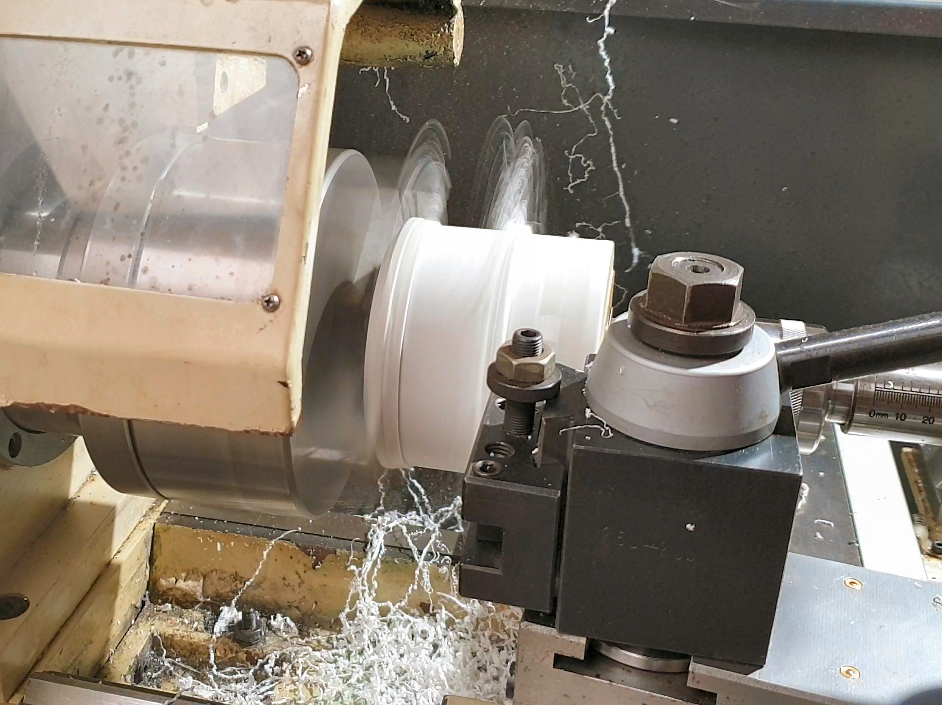
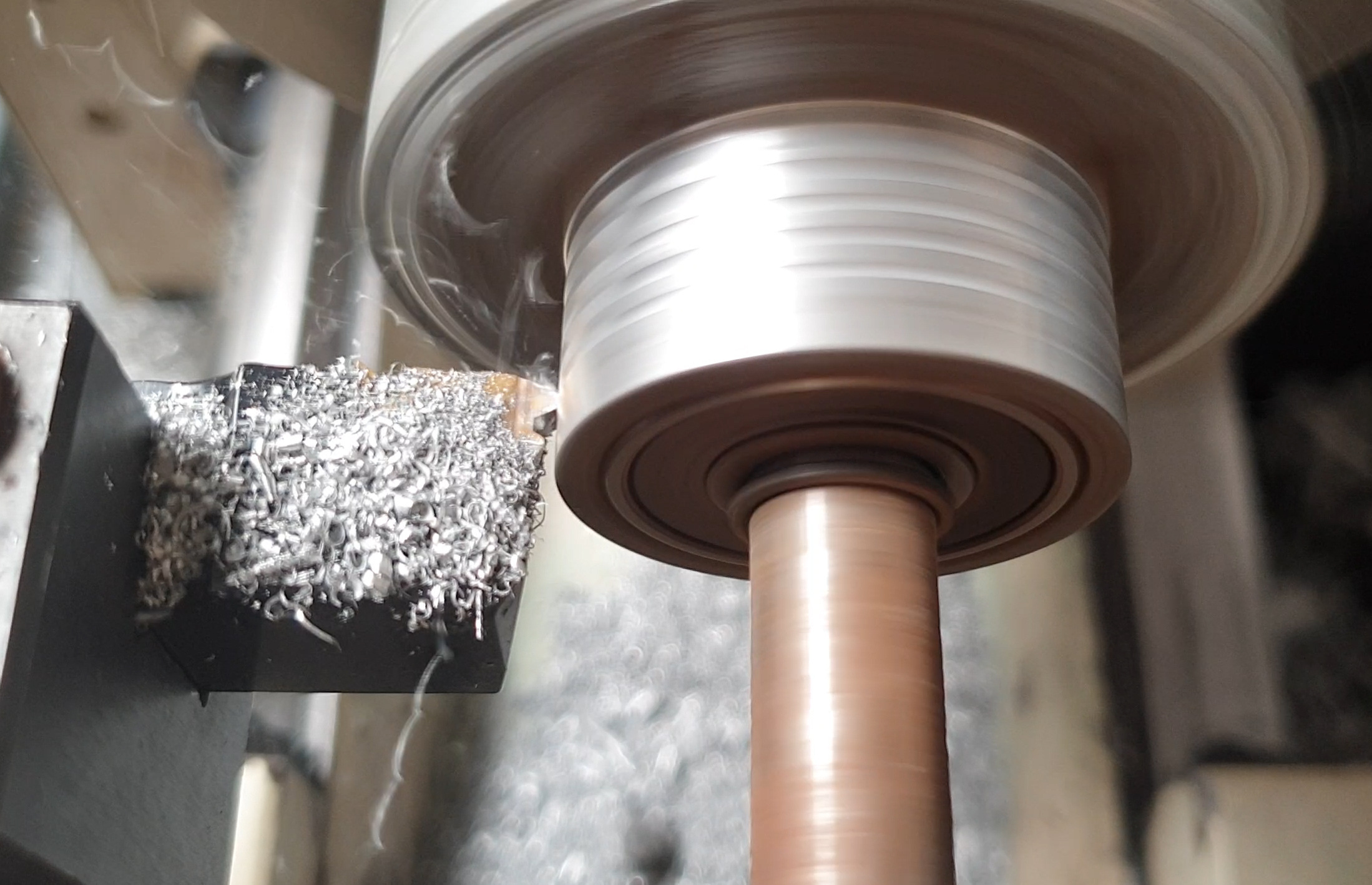
Using a part from a broken old belt sander that I was given, I turned up the small pulley on the lathe. I am using another poly-v belt (from another old washing machine), so the grooves were made using a 60 degree threading tool - it may not be the exact profile - but it is close enough... Poly-v belts are very useful in that they can work with much smaller pulleys than a standard v-belt would.
More Pulley Talk


I could have gone to town and cast the larger section of the pulley from scrap aluminium but at the speeds and forces involved a plywood pulley will be ample. I trued it up on the lathe and gave it a little crown to help the belt track.
On the larger diameter pulley the surface contact area is large enough that cutting grooves is not necessary (which is just as well as it wouldn't work well in plywood!)
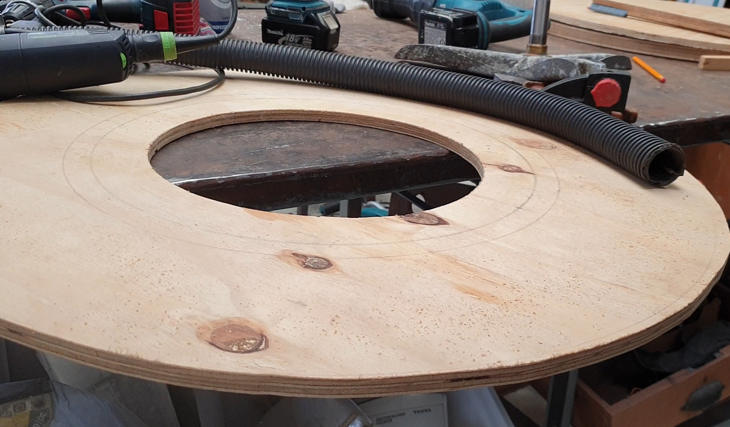
Joining on the Largee Ply Pulley


To mount the ply pulley onto the bearings and smaller aluminium one I made, I cut a hole in it with a holesaw, and then carefully turned the hole to size...
New 75:1 Speed Reduction!


With the larger glued to the smaller pulley and some tensioning mounts made, it was time to test this out!
It works! Turning it by hand and counting the revolutions we now have a seventy five to one speed reduction.
That means that when the platter is spinning at 50rpm (roughly what I am aiming for on the mulling machine (which will be probably be the most burdensome load), the motor will be going at 3,750rpm. That's still not the most optimum for a motor of this type, which is probably more like 7000rpm, but it's a big improvement!
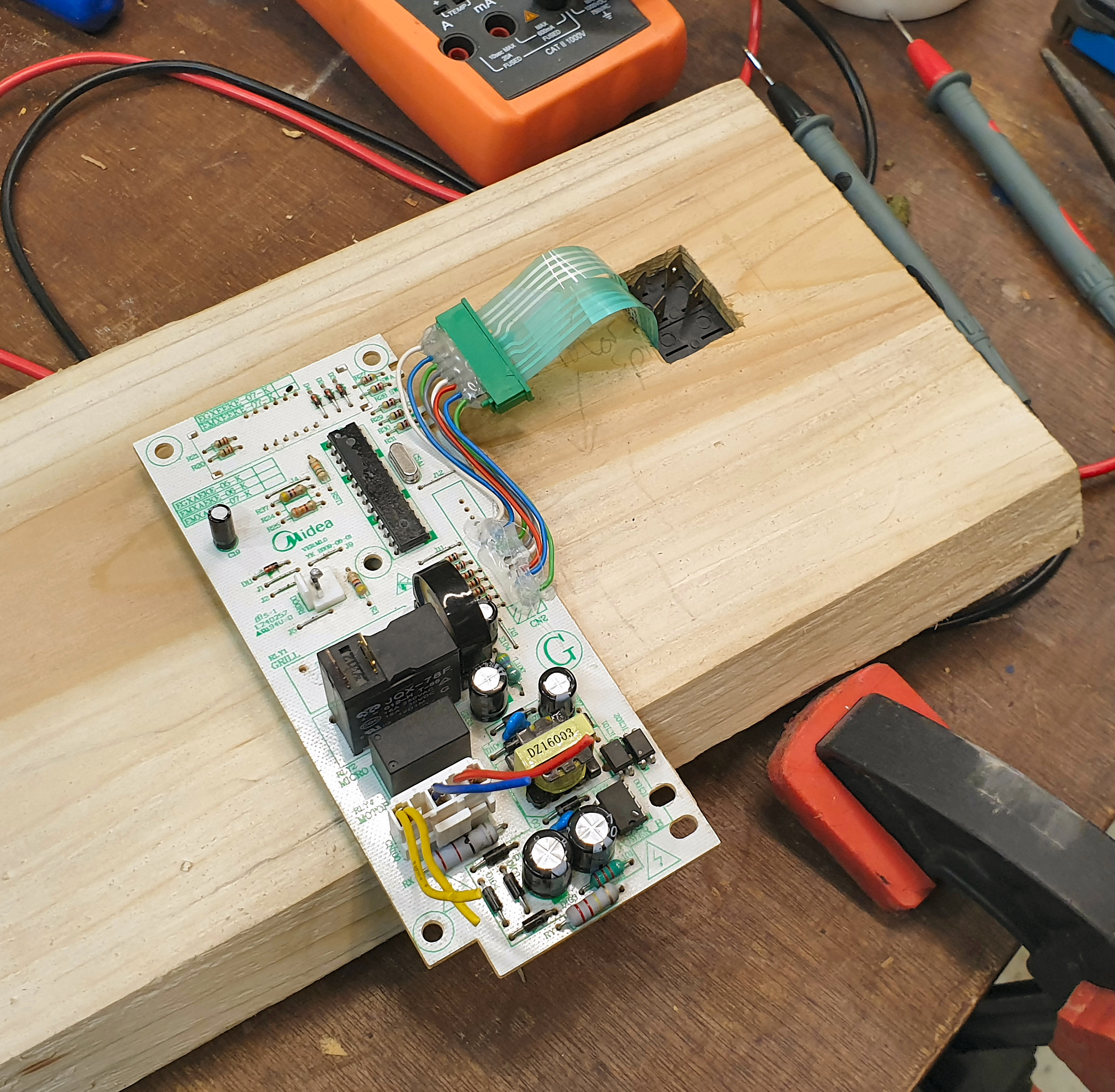
Adding a Microwave Timer #1 So Simple!


I could have simply bolted the microwave timer to the side of the machine, but I wanted something a bit more integrated. To do that it needed a but of further dismantling... The stick on keypad can be peeled away, and unplugged. From here we can stick it where we like on our control panel.
Microwave Timer #2 - Re-mounting the Keypad & Readout


A small recess in the panel was cut with tablesaw and chisel, into which nestles the keypad. I got lucky and with a little fettling the ribbon cable fit perfectly through the power switch hole,
Then I cut a hole with the scrollsaw for the digital readout.
Microwave Timer #3 - Position and Stick on Keypad


It is possible to make a whole new face for the keypad, changing the button names names to be less microwave/food oriented. It;s not necessary though, and I was happy with the visible roots of the device.
After cutting the keypad to size with scissors (don't cut through any of the wire traces), all that's left is making a little extension for the ribbon cable that's not quite long enough to reach.
Microwave Timer #4 - Cable Extension


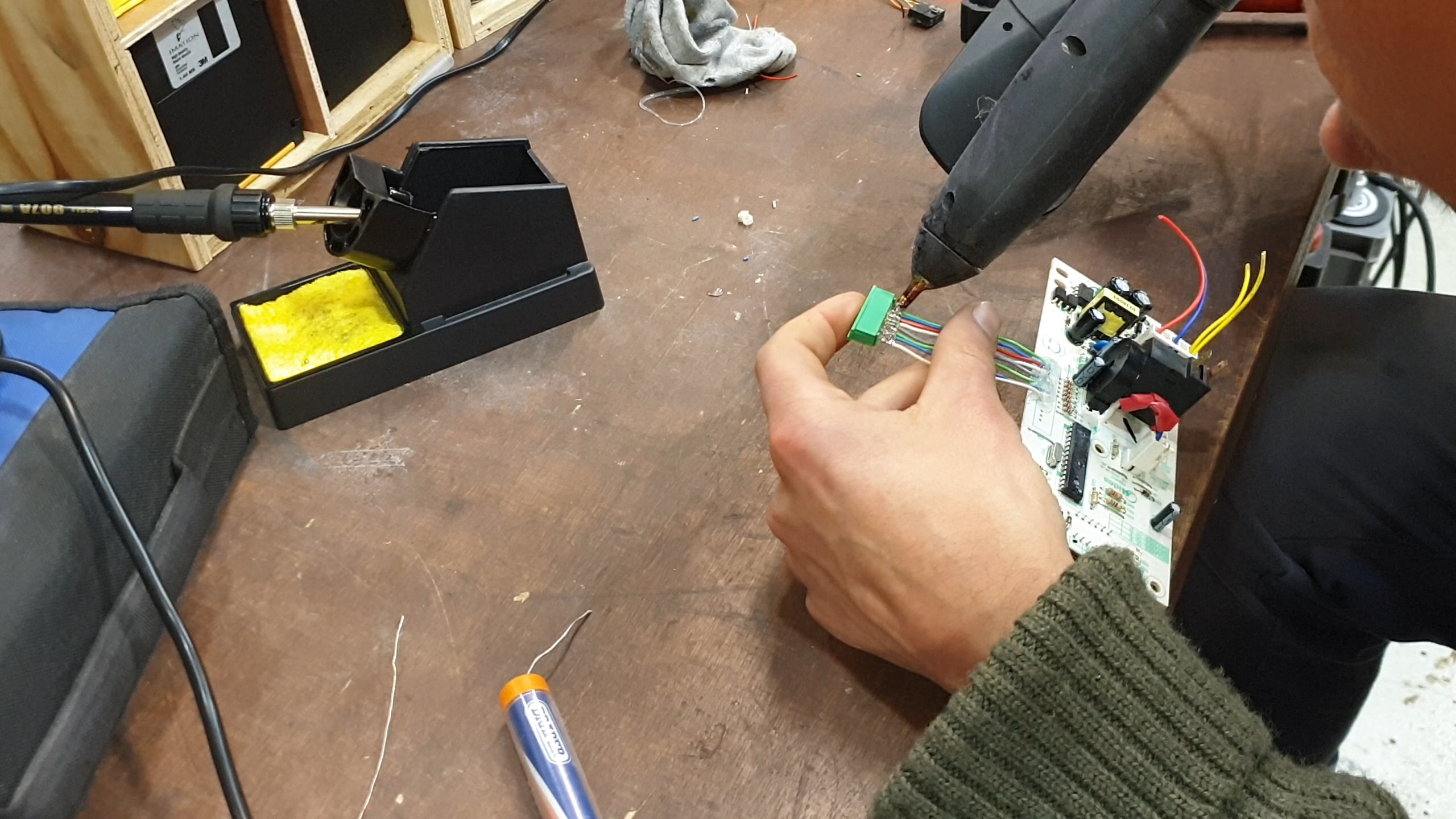


This is a question of unsoldering the connector from the pcb, and soldering in wires. Easy to say - a bit fiddly to do... But it worked nicely.
I added a healthy bead of hot melt around all the soldered joints for insulation and strain relief.
360 Degree Photo Booth #1 - the White Screen


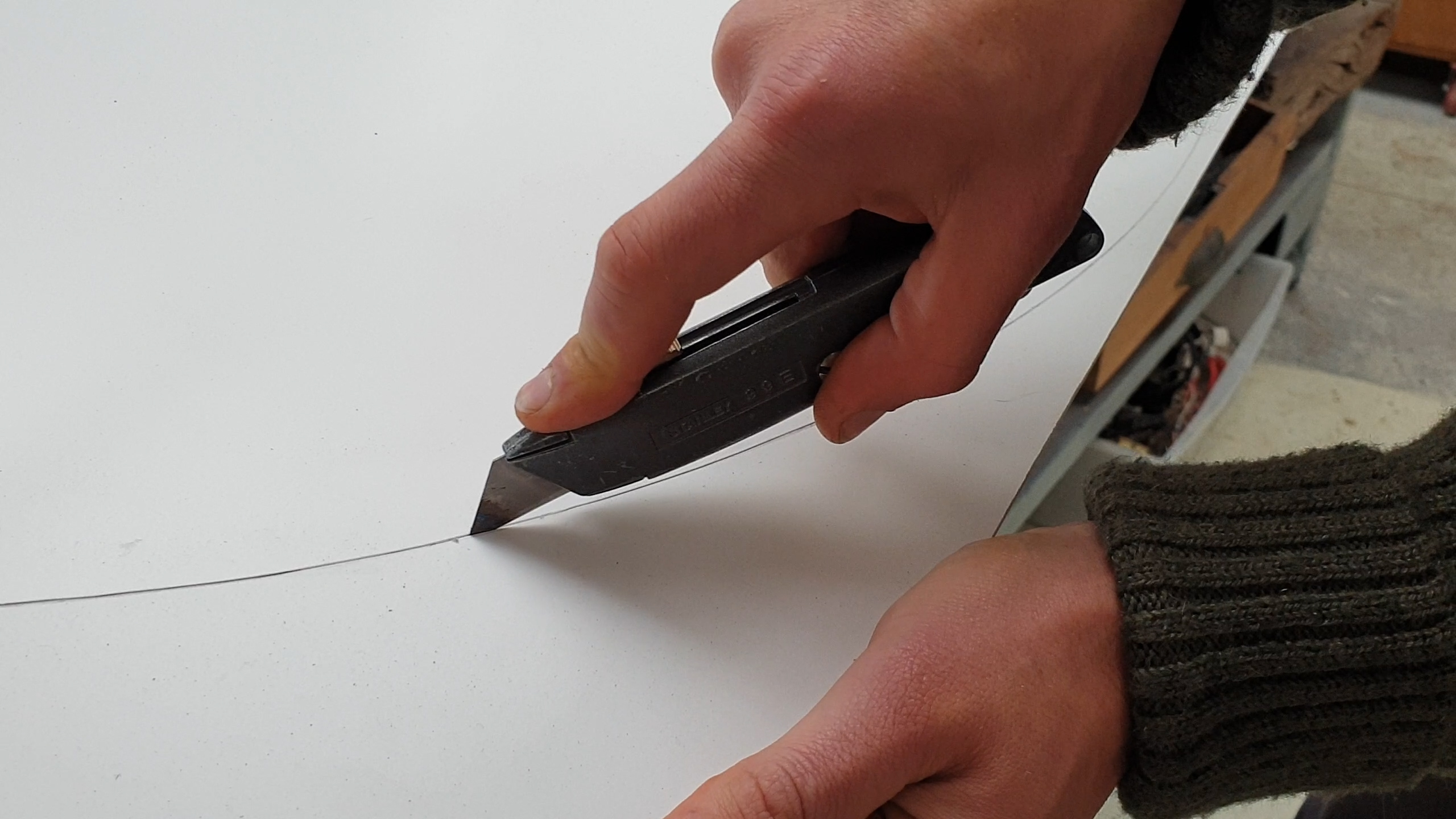
I wanted to be able to film interesting curiosities rotating without the distractions of a background, or the difficulty of moving the camera around the item (hard to do smoothly).
I had a big bit of 'plastic card' (I don't know what else to call it?) I had fished from a skip....
360 Degree Photo Booth #2 Use


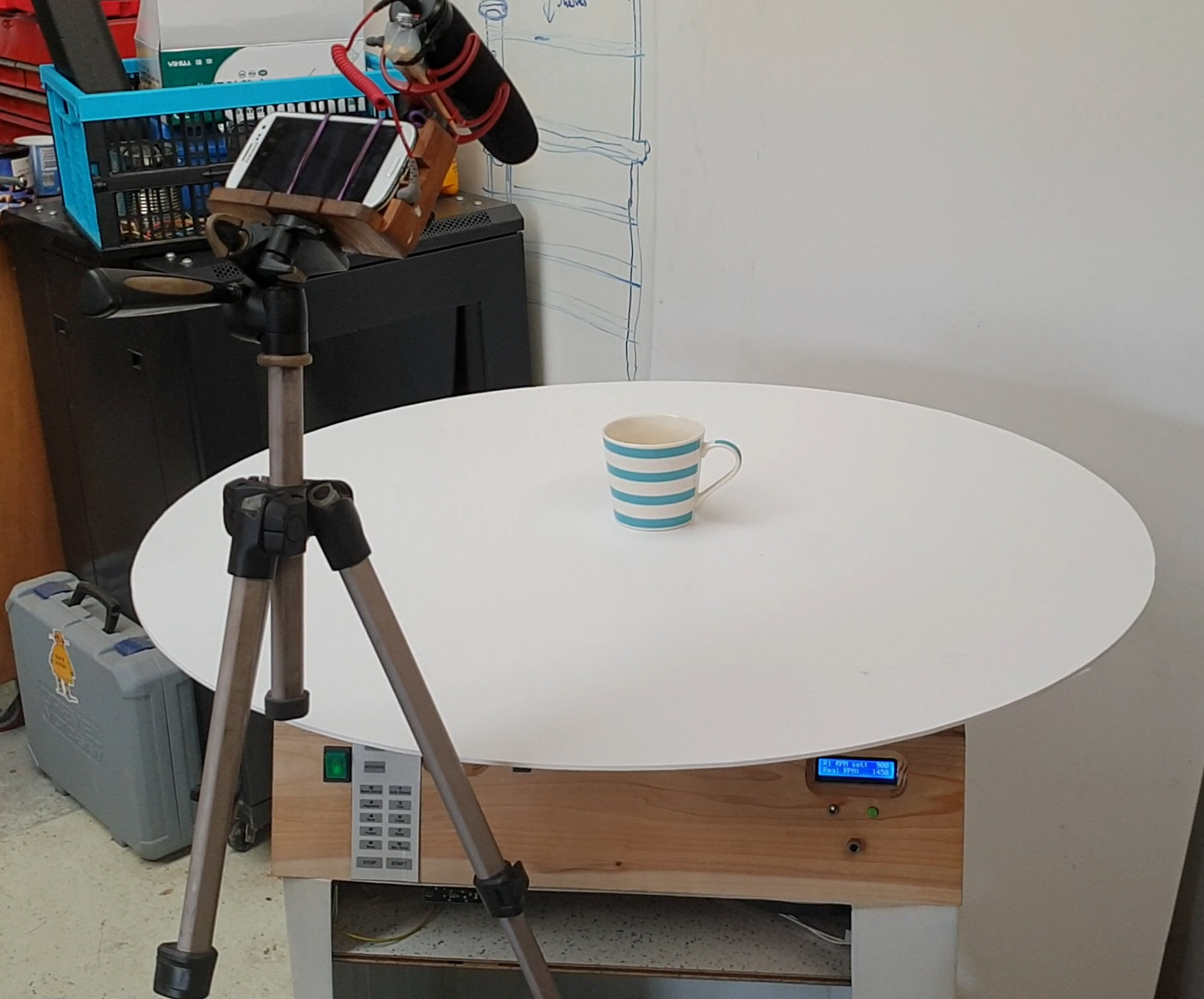
I will upload vids when I get the chance, But here it is in use - rotating nice and slow, It works well :D
Lighting is very important...
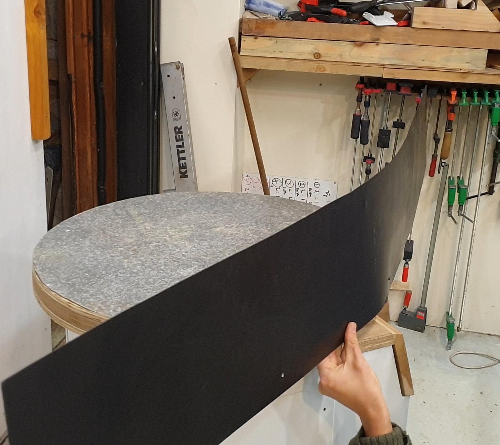
Green Sand Muller #1 - Adding the Bowl


Just in case you are wondering, "green sand" is a mix of sand, clay, water and secret ingredients, that you use to make moulds for casting molten metal things (you can check out my adventures in aluminium casting on my YouTube channel here: https://www.youtube.com/floweringelbow.) Making, and re-conditioning great green sand is something of an art form and takes a very long time by hand. A mulling machine set on a timer does it for you...
The bowl for the mulling machine is made from a scrap of galvanised sheet metal, I dug out of the ground at my parents farm... I imagined that the sand would quite quickly eat away at the bare plywood, and I needed welding splatter protection anyway....
The circular base was simply drawn out with the compass, roughly cut out with an angle grinder and stuck down to the platter with double sided tape..Once in position I was able to true it up with the flap-disk on the angle grinder as the platter rotated..
Green Sand Muller #2 Drilling and Fixing the Bowl's Sides


The edges of the bowl are made from two scraps (much more awkward than one long piece would have been, but sometimes you gotta work with what you got) that are drilled and screwed to the plywood platter.
As you see, I painted these bits black on the outer face as this part of the galvanising was warn away and rusty...
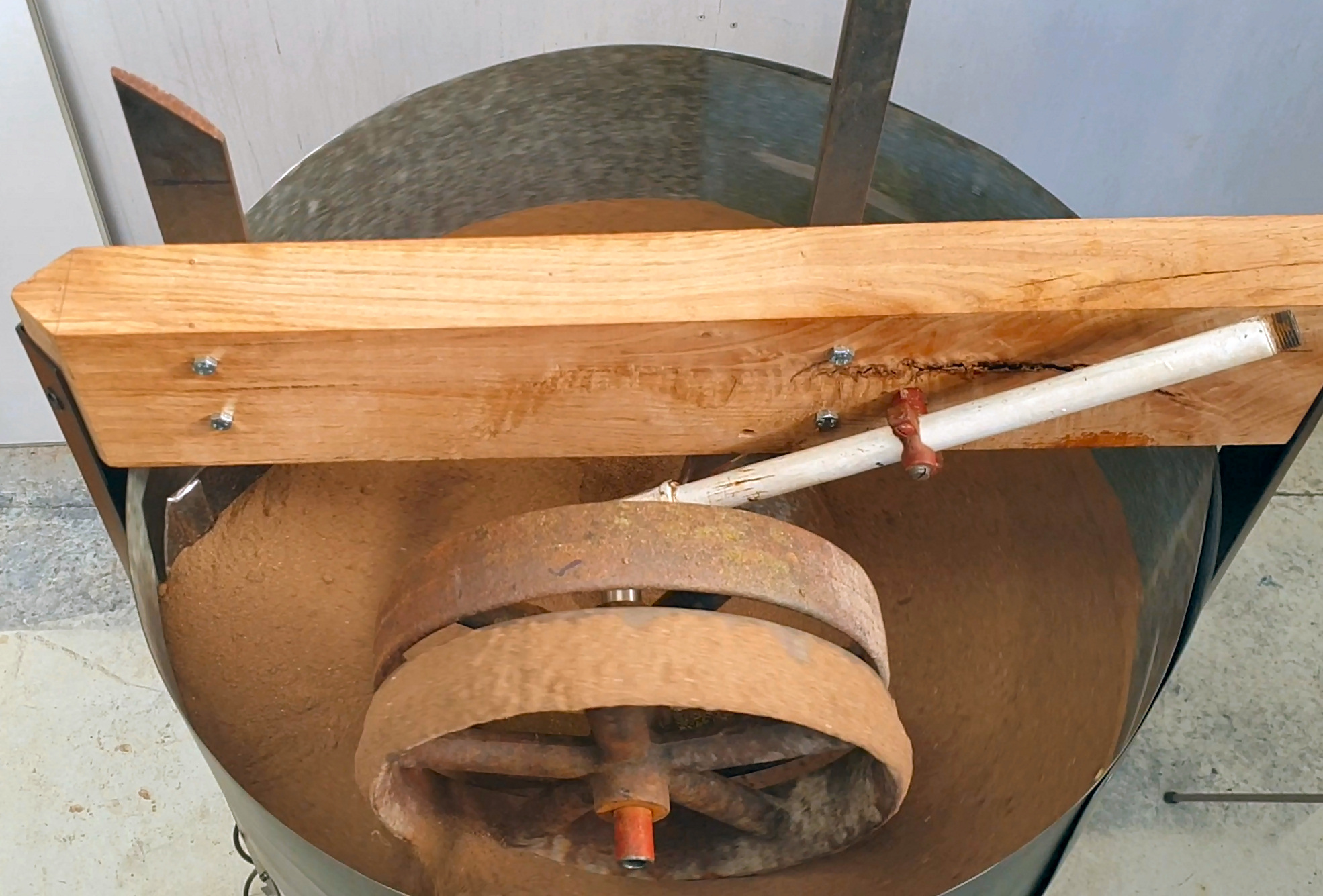
Green Sand Muller #3 - the Over Frame - Prep


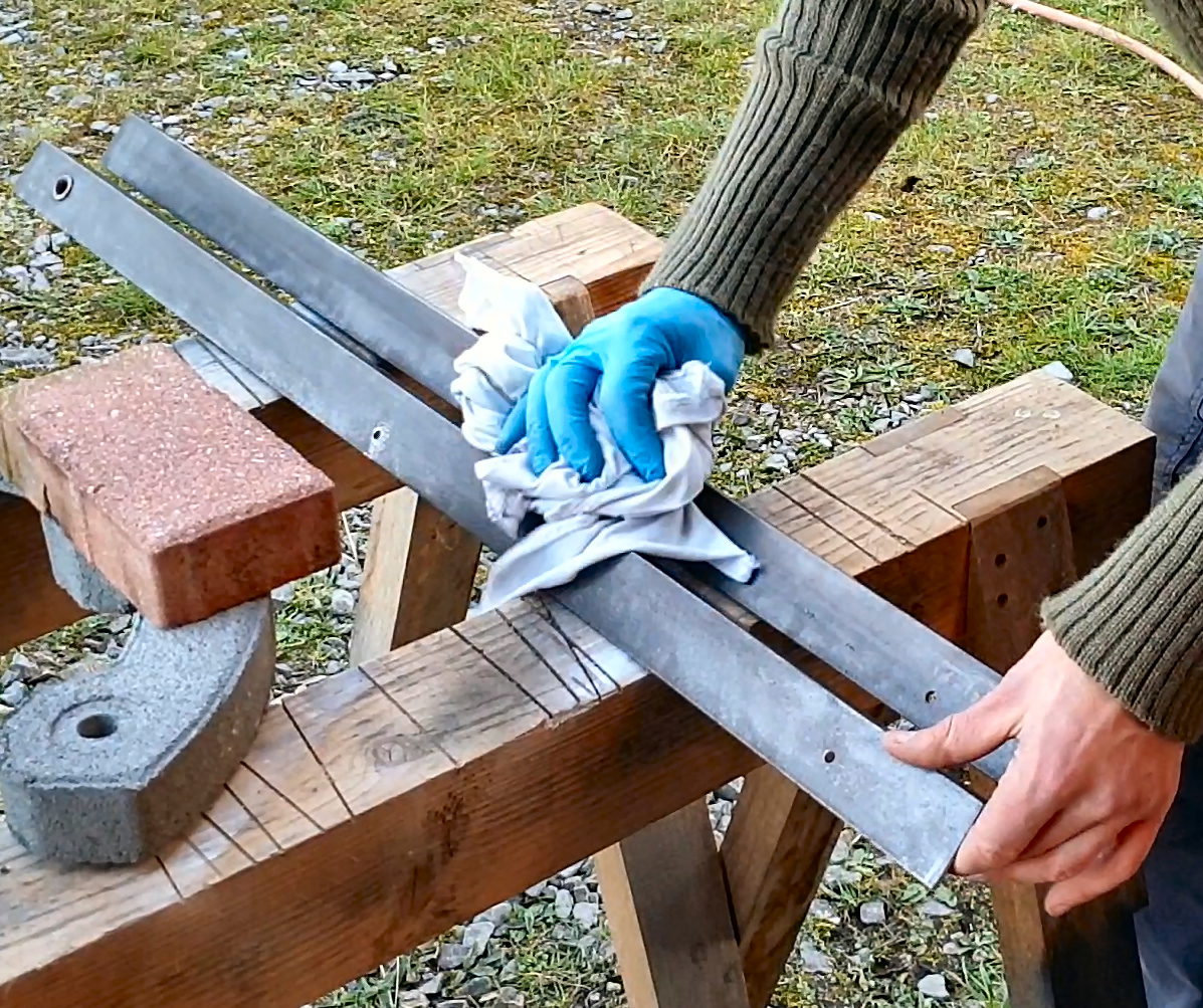


To make the over-frame that supports the plough and wheel, we can use some scraps of angle iron that came from an unwanted old bed frame...
To make the cross piece I am using an 'off cut' (admittedly a rather nice off cut) of oak. This should be plenty strong enough, and be easy to attach the wheel and plough to.
Green Sand Muller #4 - the Over Frame - Assembly


The angle iron is bolted to the corners of the washing machine frame, and the Oak cross piece spans the gap between them. This is in testing, so we will see how rigid it is in use...
Green Sand Muller #5 - Compacting Wheels


I spend a while wondering what I would use for the compacting wheel for the muller. I thought about casting concrete in a section of old plastic barrel, and was getting ready to make that, when I found these cast iron bad boys, mostly berried, while out for a walk on my parents farm... Jackpot :D
They are plenty heavy enough and about the right size, and as it happens a scrap of pipe I have been hording fits perfectly as an axle. All I needed to do was cut it down a bit, make a 90 degree joint, and add a little spacer.
Then a 1/2" hole was drilled through the oak crossbar and the little pivoting mount you see in the third pic, threaded through.
Green Sand Muller #6 - Making the Ploughs


The ploughs are there to shove the sand about - to turn it over and mix it up, before it once more finds its way under the wheels which crush out any lumps.
After scouring my scraps pile, I eventually came up with a bit of old gas bottle, the remains of when I made my experimental self feeding wood burner I think...
Anyway, I cut it with the angle grinder, into shapes that looked like they would work for scooping and shifting sand. That done, I made some slots (drilling and hand file) in some steel bar off-cuts to make the 'plough handles'.
To weld the handles to the two ploughs I put things in place, on the muller, and tack welded them, before laying the assembly on the bench and welding properly.
Green Sand Muller #7 - Fitting Ploughs


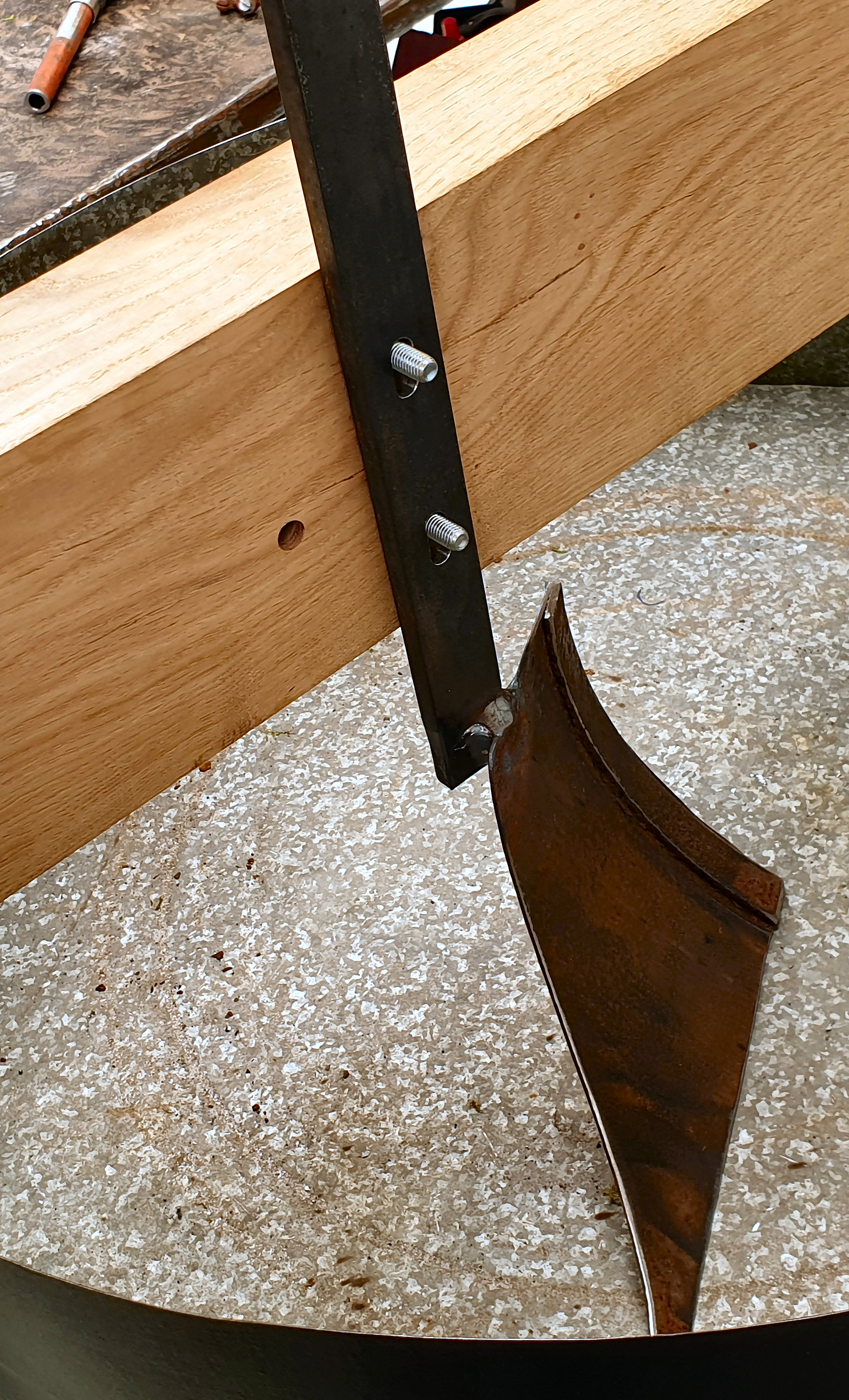

To fit the ploughs, the oak crossbar is drilled to fit some 8mm bolts.
Next put a sliver of wood under the blade, so it is held just off the platter - at about the height we want it. Then tighten the bolts nice and tight, clamping the handles to the crossbar.
Green Sand Muller - Use


It required a little fiddling to get this working well - a touch more tension on the belts, adjusting the plough blades slightly, etc etc.. But it does work! And very well. Yipppy.
I can set the microwave timer, and off it goes mulling up the sand... Water can easily be added to make it the right consistency, and it quickly gets evenly mixed throughout the green sand.
While you're here I may as well share my recipe for green sand:
10% finely ground bentonite clay (cat litter), 90% fine beach sand, some water, that's it! I may experiment with some more exotic mixes now I have easy mixing technology..
Here a little video of it in action https://www.facebook.com/floweringelbow/videos/987... (sorry it's on FB for the mo. Will upload and embed when I get a chance).
Green Sand Muller - Problems and Solutions


In general this is working great. There are a few little problems that needed/still need attention:
1. I found that only one of the two wheels was doing much, the other was not rotating. After stiffing up the pivot/mount (see note) of the pipe that holds the wheels, they were held more square to the platter and now both rotate. Solved
2. When I added water to the green sand, clumps of it would stick to the crushing wheels (you can see this is the video linked to in the last step). Not really a big problem, as you can just brush it off at the end, but that all adds time to a process that I want automated. To fix this I wrapped the face of the wheel in a slick plastic repair tape. Solved
3. The Wheels squeaked too much... Greased the pipe shaft - should have done this from the off, but was just testing the principal of the contraption.Solved
4. In greasing the shaft I made an excellent adhesive for fine particles of sand. I see this happening already, and if left unchecked this will quickly wear the shaft wheel interface. I should therefore add a rubber seal of some kind. Yet to do...
5. The outermost plough blade periodically scrape on the side of the basin. Functionally this is fine, but it makes a noise much like a hyperactive cockerel riding in a poorly maintained wheelbarrow... I thought I had fixed this by slight adjustment, but after re-filling with sand, it turns out that the added force of the sand on the blade, pushes a smidgen more towards the outer edge and it still scrapes.... Still need to sort this...
Apart from that this is working great - well please :D
Rotary Welding Positioner
Coming very soon.
Parting Thoughts

Friend, thanks so much for checking out this instructable! Like the chiansaw milling instructable that I have modified and updated a LOT over the years, this too can be seen as a living thing. I will edit and add to it as I learn and experience what this machine has to offer. There is plenty to discover as I morph and use this machine for welding and pottery.
I also respond to your suggestions and ideas, so don't be shy in leaving comments!
Next on the list of things to do for this machine:
- Add casters (not sure if I am going to make them from scratch - casting wheels etc. - or not)
- Add a few more shelves and fit door to the internal storage area. I'll use this to hold my green sand and pattern making tools.
- Wire brush crushing wheels of their rust and paint non-active surfaces black
- Work on the rotating welding table
If you found some of that interesting, please do connect! Leave a comment below, share this with your upcycling friends, check out my YouTube channel FlowerinfElbow, subscribe to me here on instructables, and/or come see me on Facebook here.
I learned a lot from the many mistakes that I made during this build, I'm quite looking forward to making some more!