Music to Painting Robot - TechnoResonance
by hclegg26 in Circuits > Raspberry Pi
55 Views, 1 Favorites, 0 Comments
Music to Painting Robot - TechnoResonance
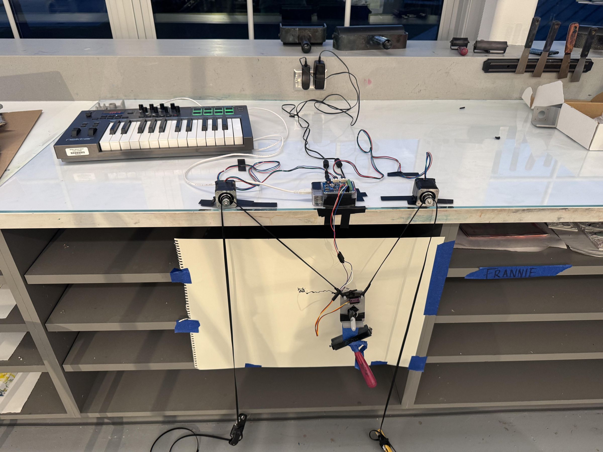
TechnoResonance is an XY plotter drawing robot controlled by a MIDI keyboard. When you press keys on the keyboard, the robot moves a pen across a canvas and dips it into paint therefore translating musical input into physical, visual art.
The system is built around a Raspberry Pi with a Stepper Motor HAT, two NEMA 17 stepper motors for X/Y axis movement, and a servo motor to lift and lower the pen/brush.
This Instructable will walk you through every step needed to build your own TechnoResonance robot: wiring the electronics, 3D printing the XY plotter, and assembling the full system.
Supplies
Git Repo for code: https://github.com/vhu26/TechnoResonance.git
3D printing for Vertical XY plotter: https://www.instructables.com/VERTICAL-X-Y-PLOTTER-DRAWING-ROBOT-ARDUINO-PLOTTER/
Raspberry Pi (any model with 40-pin GPIO) | 1 |
Adafruit DC & Stepper Motor HAT | 1 |
NEMA 17 Stepper Motor | 2 |
Servo Motor (SG90 or MG996R) | 1 |
USB MIDI Keyboard | 1 |
5V–12V DC Power Supply (barrel jack, 3A+) | 1 |
Jumper wires (male–female) | 1 pack |
Micro USB cable (for Pi power) | 1 |
#4 screws and nuts assortment | 1 pack |
Circuit Assembly

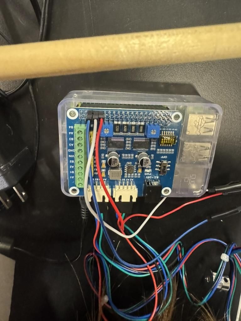
Note: plug MIDI keyboard into raspberry pi
Step 1.1— Stack the Motor HAT on the Raspberry Pi
1. Power off the Raspberry Pi completely.
2. Align the Motor HAT's 40-pin female header with the Raspberry Pi's 40-pin GPIO header.
3. Press the HAT down firmly and evenly until it is fully seated.
4. The HAT should sit flat and flush on top of the Pi.
Step 1.2 — Wire the X Axis Stepper Motor (M1/M2)
1. Connect the four wires of the first NEMA 17 stepper motor:
- Coil A+ → M1 terminal A
- Coil A- → M1 terminal B
- Coil B+ → M2 terminal A
- Coil B- → M2 terminal B
3. Tighten all screw terminals firmly.
4. Run the X-axis test script to verify movement: Test code location: In git repo named motor_test.py
Step 1.3 — Wire the Servo Motor (Pen Lift)
1. Connect the servo's three wires to the Raspberry Pi GPIO pins:
- Signal (orange/yellow wire) → GPIO pin 18 (PWM)
- Power (red wire) → +5V pin (pin 2 or 4)
- Ground (brown/black wire) → GND pin (pin 6)
2. Run the servo test script to confirm the pen lifts and lowers: Test code location: In git repo named servo_test.py
Step 1.4 — Connect the MIDI Keyboard
1. Plug the USB MIDI keyboard into any available USB port on the Raspberry Pi.
2. Run the MIDI test script to confirm key presses are being read
3. Press several keys and confirm their MIDI note values appear in the terminal output.
Step 1.5— Connect Power
1. Connect the 5–12V DC power supply barrel jack to the Motor HAT's power input terminal.
2. Connect the Raspberry Pi's micro USB power supply.
3. Power on the Pi and confirm the HAT's power LED illuminates.
3D Printing


3D printing for Vertical XY plotter: https://www.instructables.com/VERTICAL-X-Y-PLOTTER-DRAWING-ROBOT-ARDUINO-PLOTTER/
File:
Downloads
System Assembly
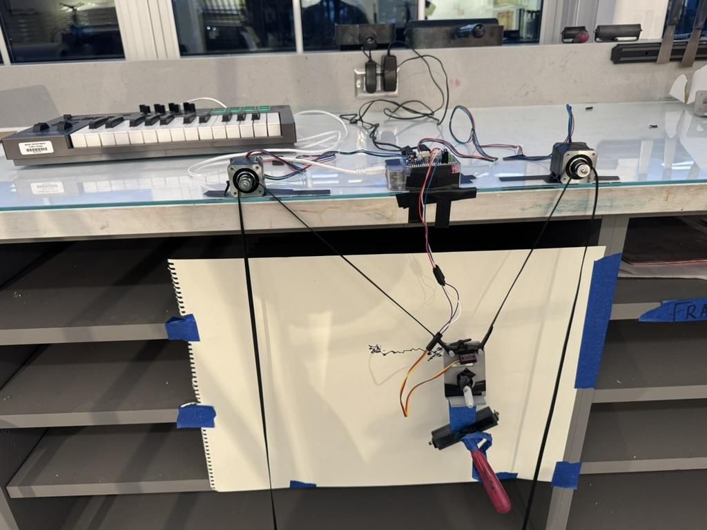
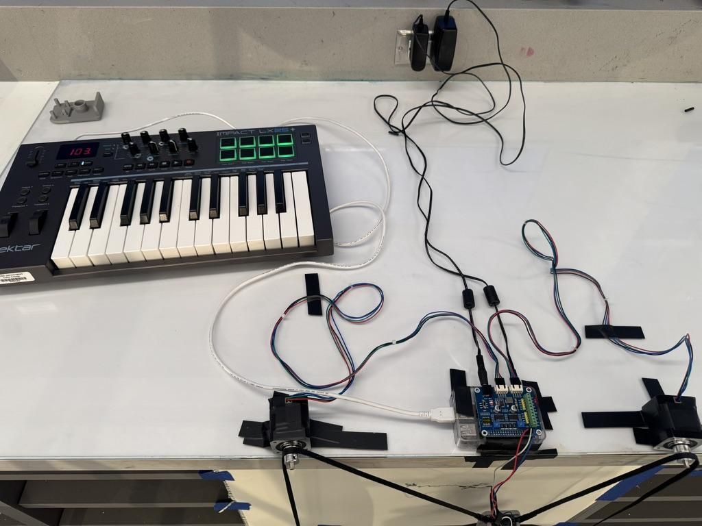
With all electronics wired and parts printed, assemble the full robot.
- Attach each NEMA 17 motor to two corners of a surface using tape and set the Raspberry Pi in the middle.
- Hang the belt down while attaching the 3D printed pen holder with the servo motor and pen mounted on.
- Connect and set the Midi keyboard next to the Raspberry Pi and motors.
- Attach speaker/headphone to keyboard.
- Connect all sources to an outlet.
- Set up paper/ canvas behind the pen.
Final test of the system:
- Run midi_plotter.py from the git repo
- Press keys on the MIDI keyboard and confirm the robot moves and draws.