NESP32 AV - Play Retro Games From a NES Controller
by DynaMight in Circuits > Electronics
168 Views, 0 Favorites, 0 Comments
NESP32 AV - Play Retro Games From a NES Controller
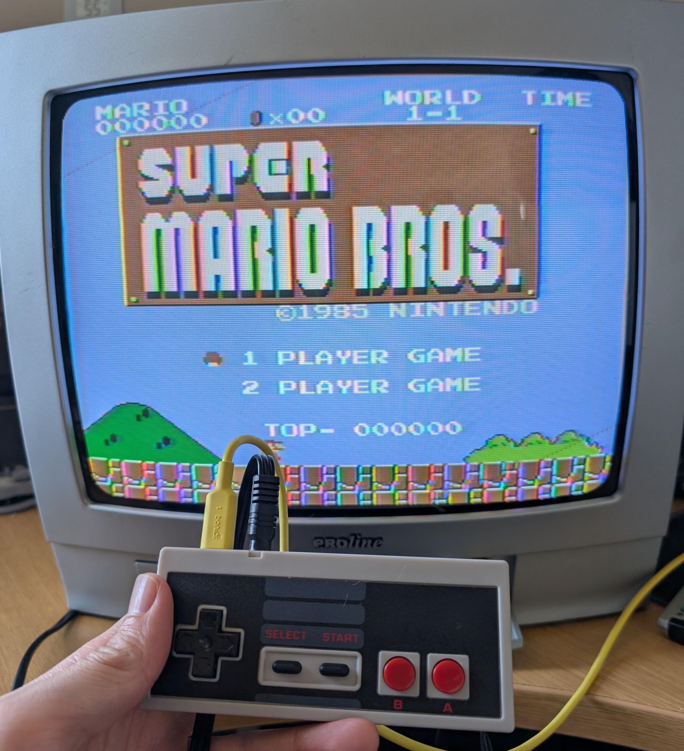
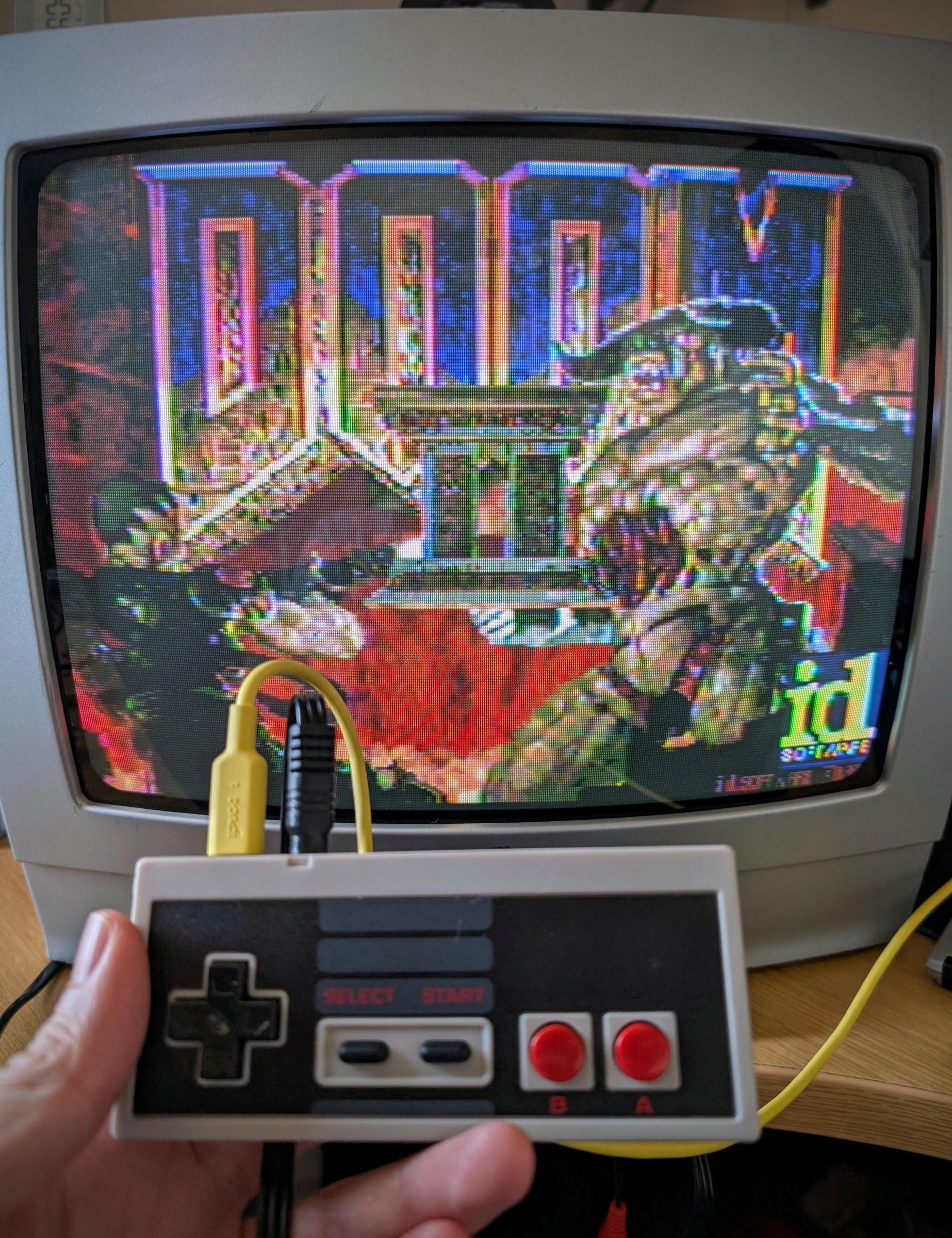
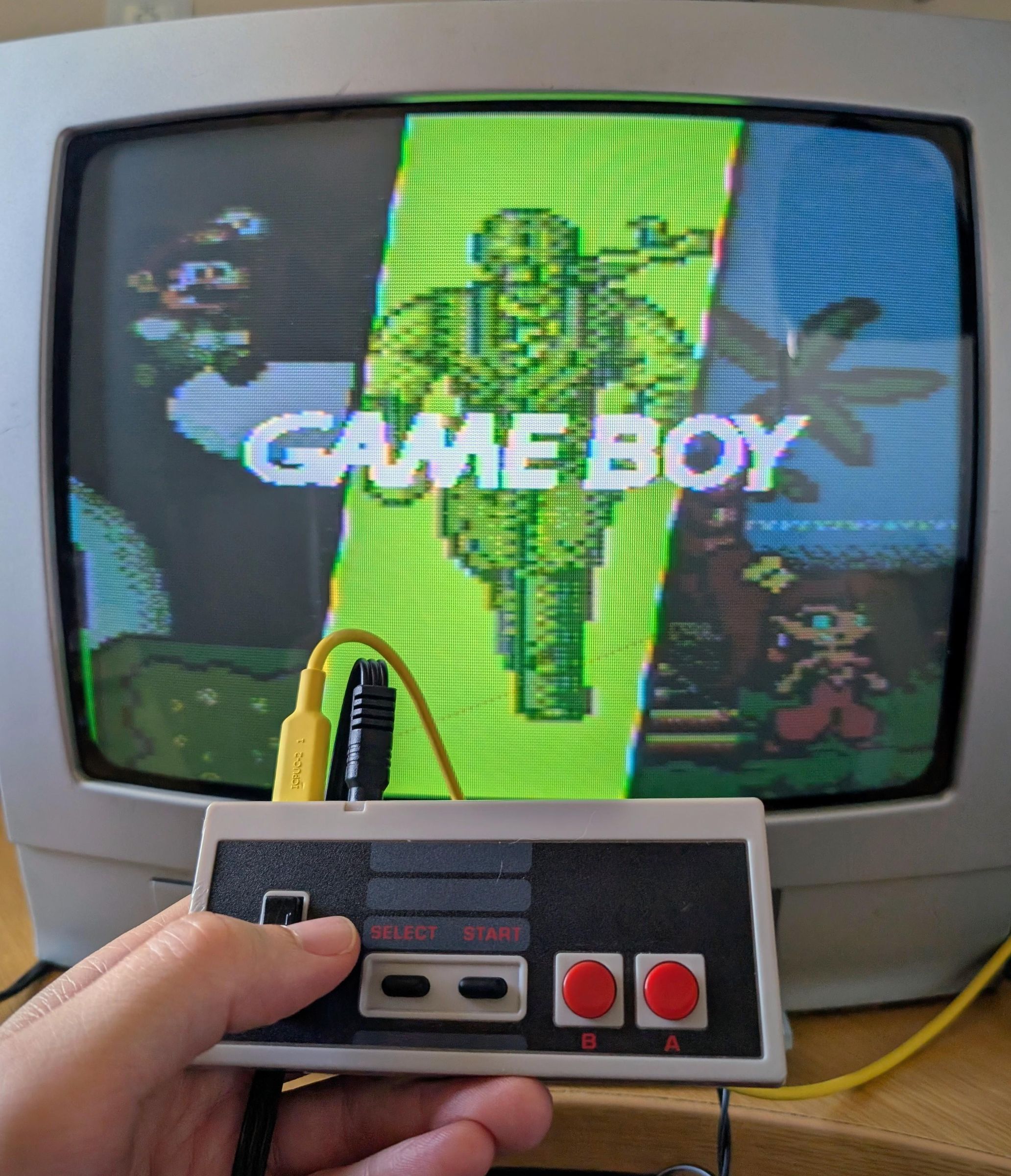
This is the sister project to my Retro-Go HDMI SNES device. I cant actually remember which one I thought of first but both came within a few days or so of each other and both had stalls, setbacks and issues at similar times actually.
I originally built a similar device back in 2020, during a Covid lockdown. It was an ESP32 that could output AV, using the amazing esp_8_bit by rossumur, it was a fun build and worked well although the emulator had some quirks, you can read up on the link but it uses the ESP32's internal sound DAC to cleverly generate video signals.
If you look at my other projects, you may see a lot of Retro-Go and thats mostly because its so well written and so easy to port to new targets/devices. I started to wonder if Retro-Go could also output to AV, in theory yes at a hardware level least as it works great on an ESP32, but whether the software side could be pulled off was another matter.
I am not a coder, so all of the software side was AI coded. At a high level we essentially have Retro-Go but with a new 'display driver' rather than outputting to a LCD, it outputs a composite signal (either NTSC or PAL). There are some drawbacks unfortunately, when Retro-Go outputs to a LCD, it sends the signals to the LCD controller and that handles a lot of the heavy lifting to create an image, however outputting to composite, the ESP32 has to essentially create the NTSC/PAL signal for every frame. We also need to generate and add in mono sound without using the internal audio DAC.
The drawback is a cost in both memory and CPU usage. Its not *terrible* but does cost, pretty much all of the core emulators such as NES, GB, GBC, GG, MS, Lynx, PCEngine, Colecovision, G&W, MSX & even Doom have enough headroom thanks to the Retro-Go developer optimising them so well, however the systems that were already pushing the limits of the original ESP32 such as SNES, MD, GBA etc now perform even worse and are therefore not even included. I have added Atari 2600 and Wolfenstein 3D since these run very well.
I honestly almost didnt release this project, due to the reduced performance (prior to some optimisation, I also had issues on the core emulators reaching full speed) and also I was testing on a cheap AV2HDMI converter and the picture quality was pretty poor... however that all changed when I got my old CRT TV down from the attic, it instantly brought the device to life (visually obviously, the performance was unchanged :) )
I am not sure how popular a device that outputs to composite in 2026 will be, most modern TV's dont even have these inputs anymore and probably wont look that great, however if you have a CRT and fancy playing some retro games on a NES controller then this project could be of some use! I spent some time creating another device for my drawer so may aswell release it, even if no-one ever builds one :) Maybe the TVOut driver will be useful to someone who wants to make a different device. The Retro-Go TVOut branch is HERE
Supplies
You will need to order the PCB's, download the gerbers HERE and send them to your chosen PCB supplier, both JLCPCB and PCBWay are popular and well priced. An aftermarket NES controller has a 1mm PCB, however an original NES controller uses a 1.6mm PCB. I originally designed the PCB for an aftermarket NES controller, I found the quality of the button feel and plastics to be suitable. I have since added support for an original NES controller however there are separate gerbers as there was enough differences that one PCB couldnt quite cater for both. So choose the gerber based on the controller you intend to use and order in the correct thickness.
As for the controller, as mentioned above, I found the aftermarket controllers suitable in both button feel and plastic quality. I would say possibly the aftermarket membranes are a little stiff... but thats me comparing to my original NES controller thats now 40 years old as has had many million button presses :) If you want an original controller, you can try local shops or eBay. If you're in the UK, I got mine from my local CeX.
NES Controller (aftermarket): https://www.aliexpress.com/item/1005006581092956.html
ESP32 WROVER 16MB N16R8: https://www.aliexpress.com/item/1005005083165398.html
USB-C Ports (6 pin): https://www.aliexpress.com/item/1005007079016649.html
AP2112K-3.3 voltage reg: https://www.aliexpress.com/item/32998839398.html
MicroSD Slots: https://www.aliexpress.com/item/1005001331379046.html
Tach Switch (3X4X2mm 2Pin): https://www.aliexpress.com/item/4001317902663.html
0603 Resistor kit (0603 720pcs 36 values): https://www.aliexpress.com/item/1005006198053993.html or separately (1k, 5.1k, 10k, & 100k): https://www.aliexpress.com/item/1005001436923851.html
0603 Capacitor Kit (0603 16Value 320pcs): https://www.aliexpress.com/item/1005002761630440.html or separately (100nF & 10uF): https://www.aliexpress.com/item/32966526545.html
0805 600 Ohm Ferrite Bead: https://www.aliexpress.com/item/1005003124199167.html
Pin headers (1x3P): https://www.aliexpress.com/item/1005011748770504.html
USB Programmer: https://www.aliexpress.com/item/1005006445462581.html
PJ-320D 3.5mm 4-Pin SMD Jack: https://www.aliexpress.com/item/1005010805681925.html
3.5mm Jack To 3 RCA cable (1m): https://www.aliexpress.com/item/1005005604133438.html (You can also use use 3.5mm > Phono cables, the ones with just Red/White phono, they will still carry video and sound)
Building the PCB
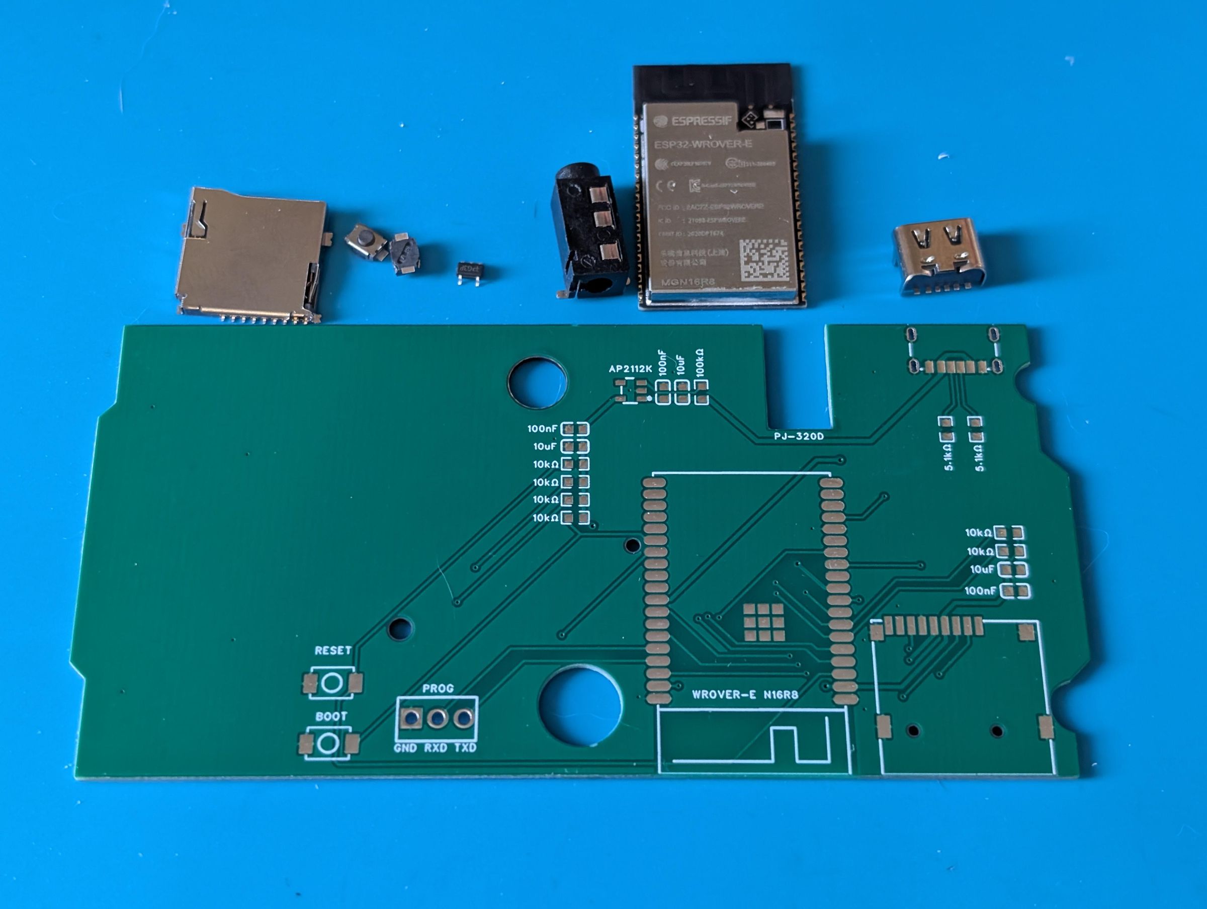
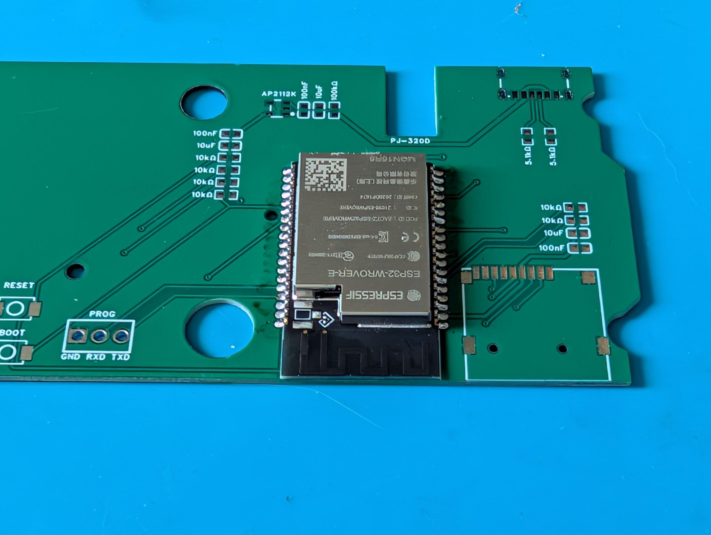
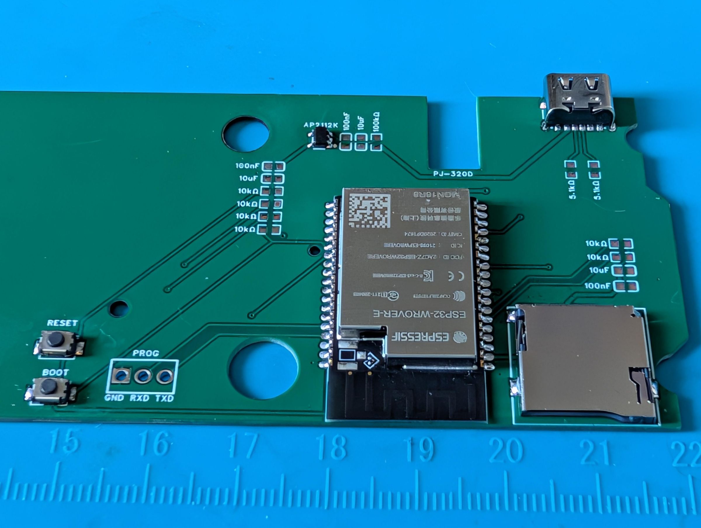
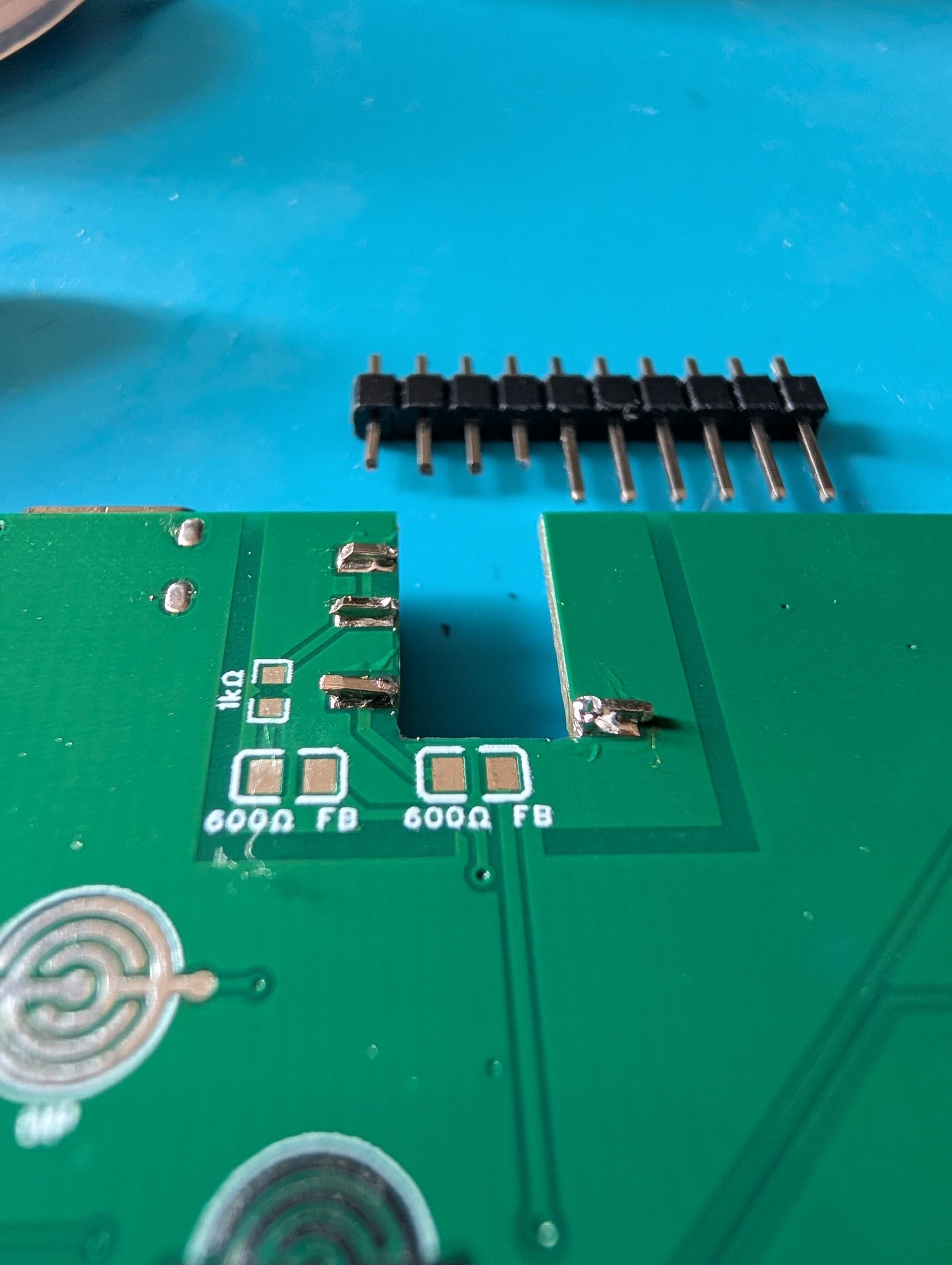
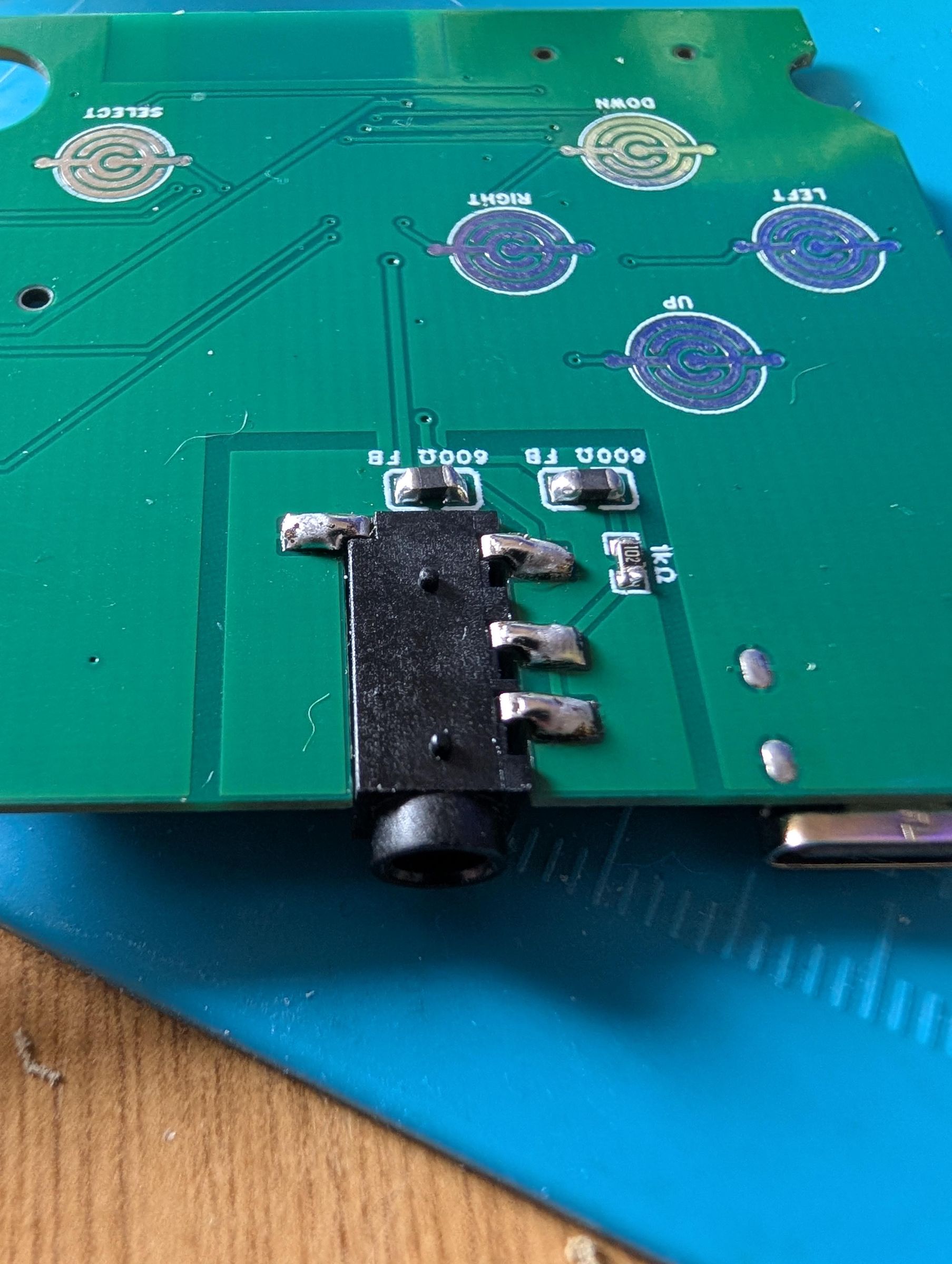
There isnt actually a load of components on this device but theres still some places that can trip you up.
The ESP32 has quite fine pitch solder points, so to solder this, I would recommend tinning one pad first, heating that pad and bringing in the ESP32 until its lined up, check both sides, once everything is lined up, tin another pad at the other end to lock it in place and solder the rest of the pads. Check for shorts between the pins with a multimeter.
You can follow the pictures to see the rough order I soldered everything, ESP32 first then USBC and SD Slot. Ensure theres no bridges and all the connections are solid. For the USBC port, ensure that the ground legs/anchors are well soldered with the solder going through the whole board, else the port may come loose.
Solder all the resistors/capacitors/tach switches etc, leaving the AV port for last.
Now its time for the janky part. I wanted the AV port to be centred, that would allow it to sit where the original NES controller cable came in, less cutting required and looked clean. I couldnt find a 3.5mm port that suited this, so this is my attempt... Check the pics but essentially I tinned the pads, cut a small, maybe 3-4mm, bit of pin header and added that to the pad, I then soldered the AV port on top of that.
You need to be careful you dont apply too much heat as this will melt the plastic in the port but as long as you get a good amount of solder, its very solid afterwards. Finish off the remaining resistor and ferrite beads.
Ofcourse you can just solder it flat to the PCB and cut/enlarge the hole in the controller instead :)
Cutting the Shell
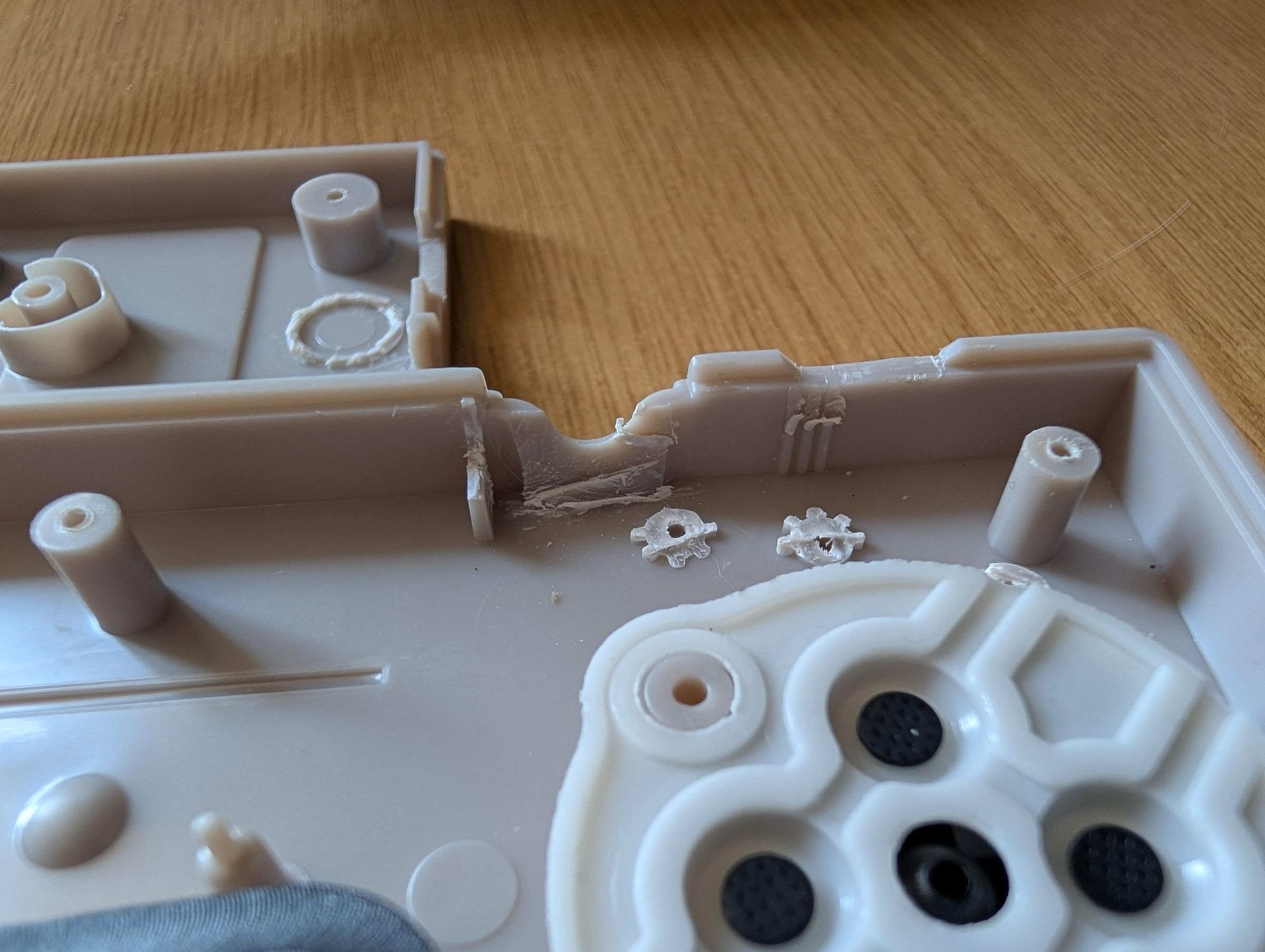
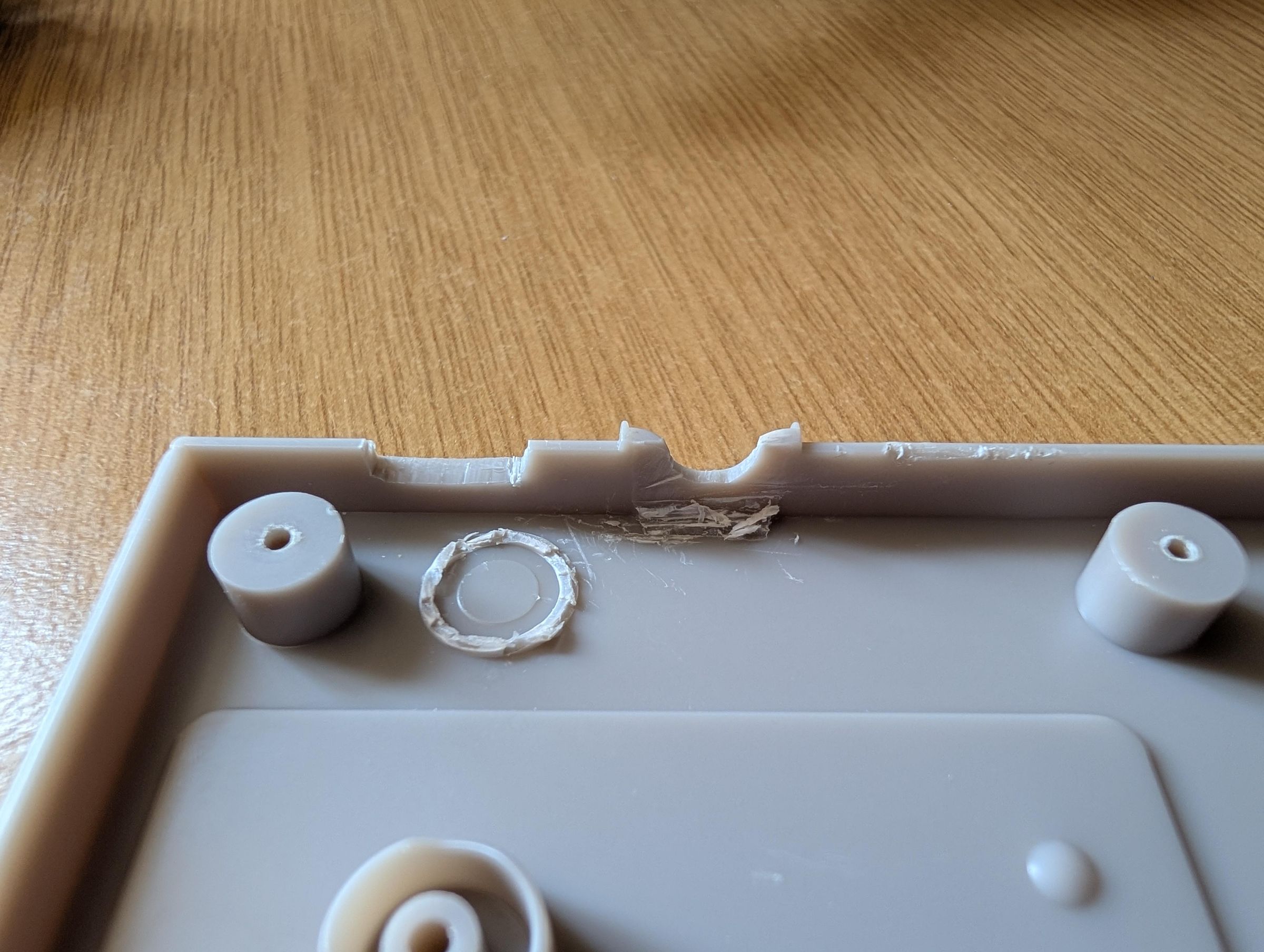
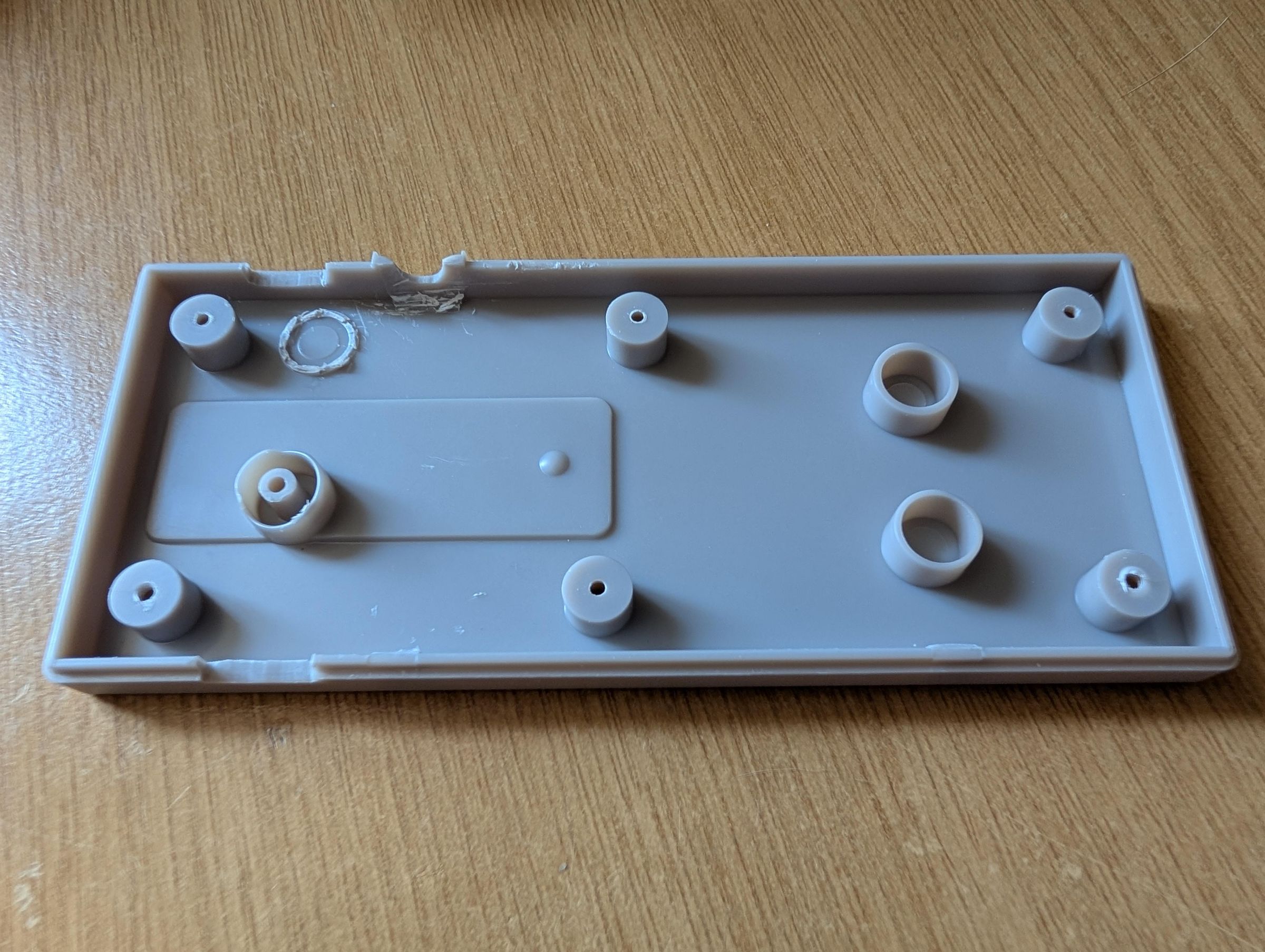
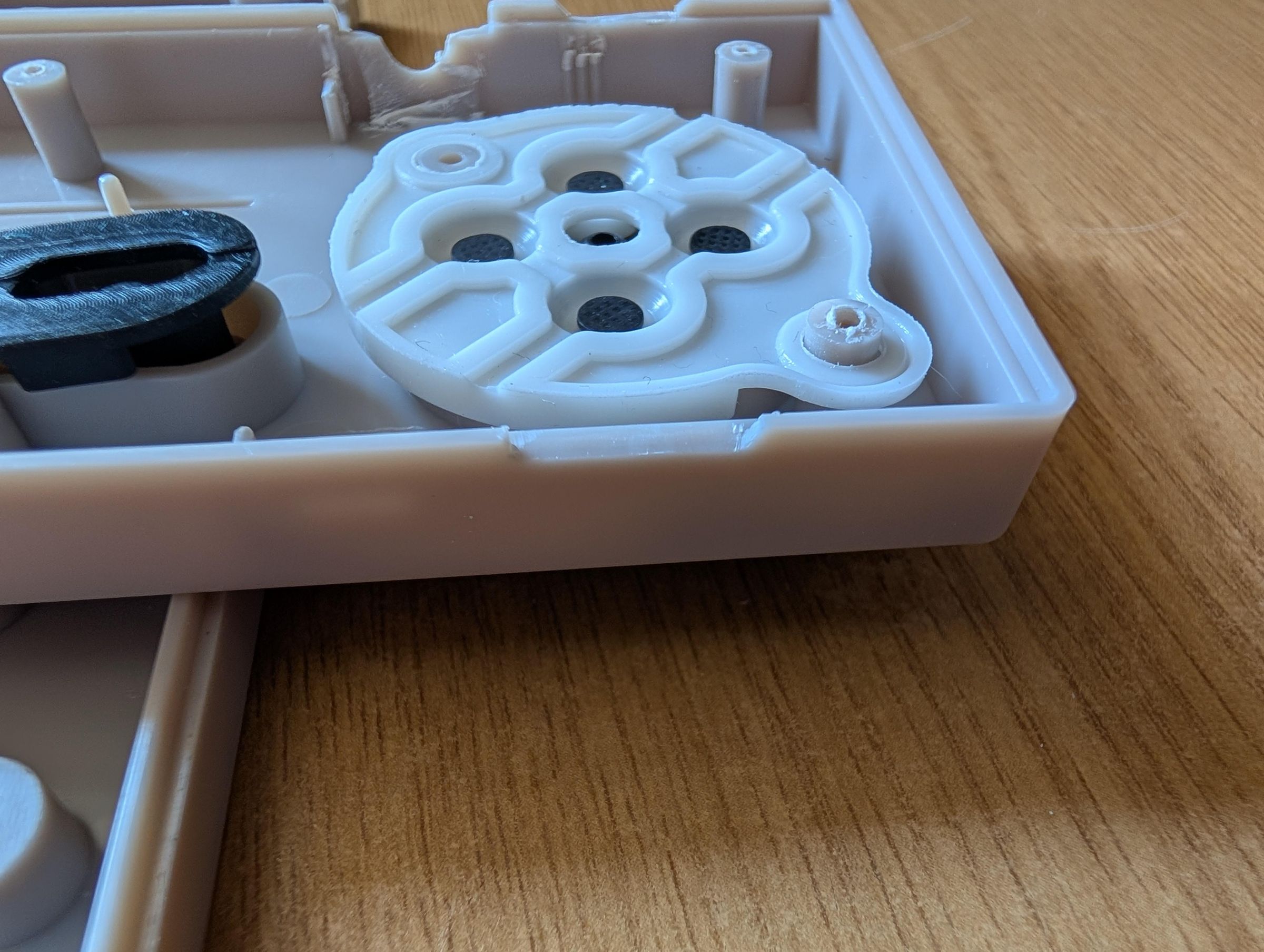
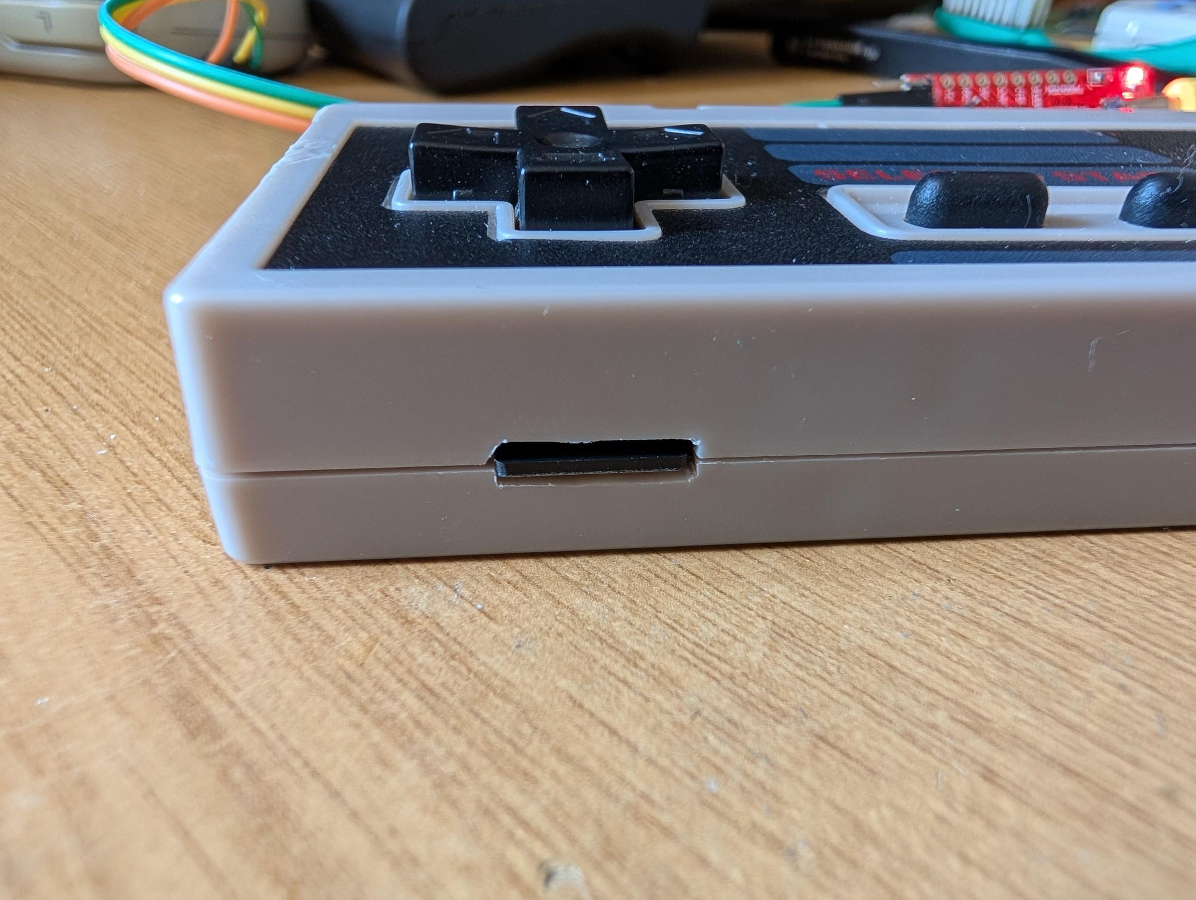
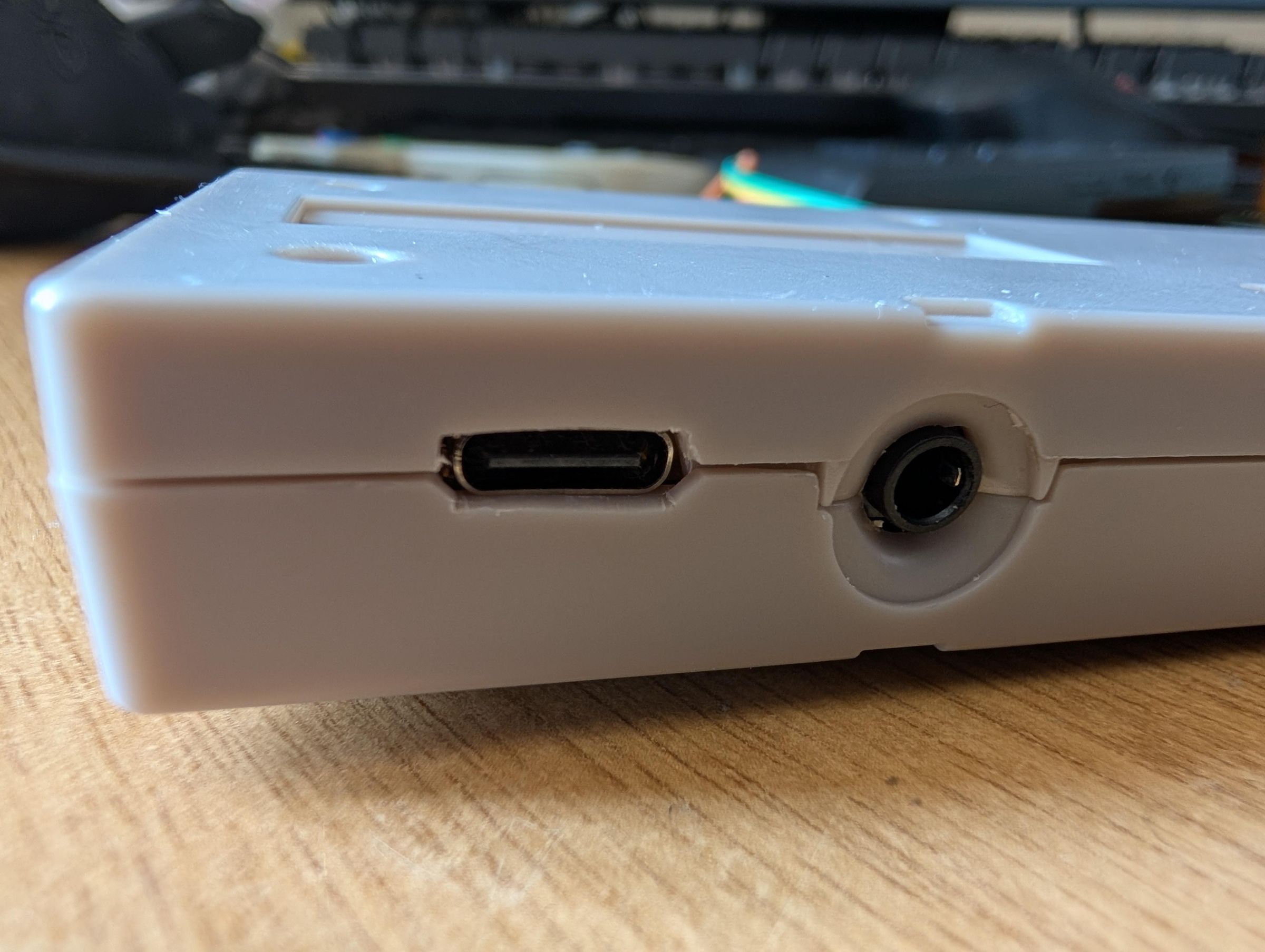
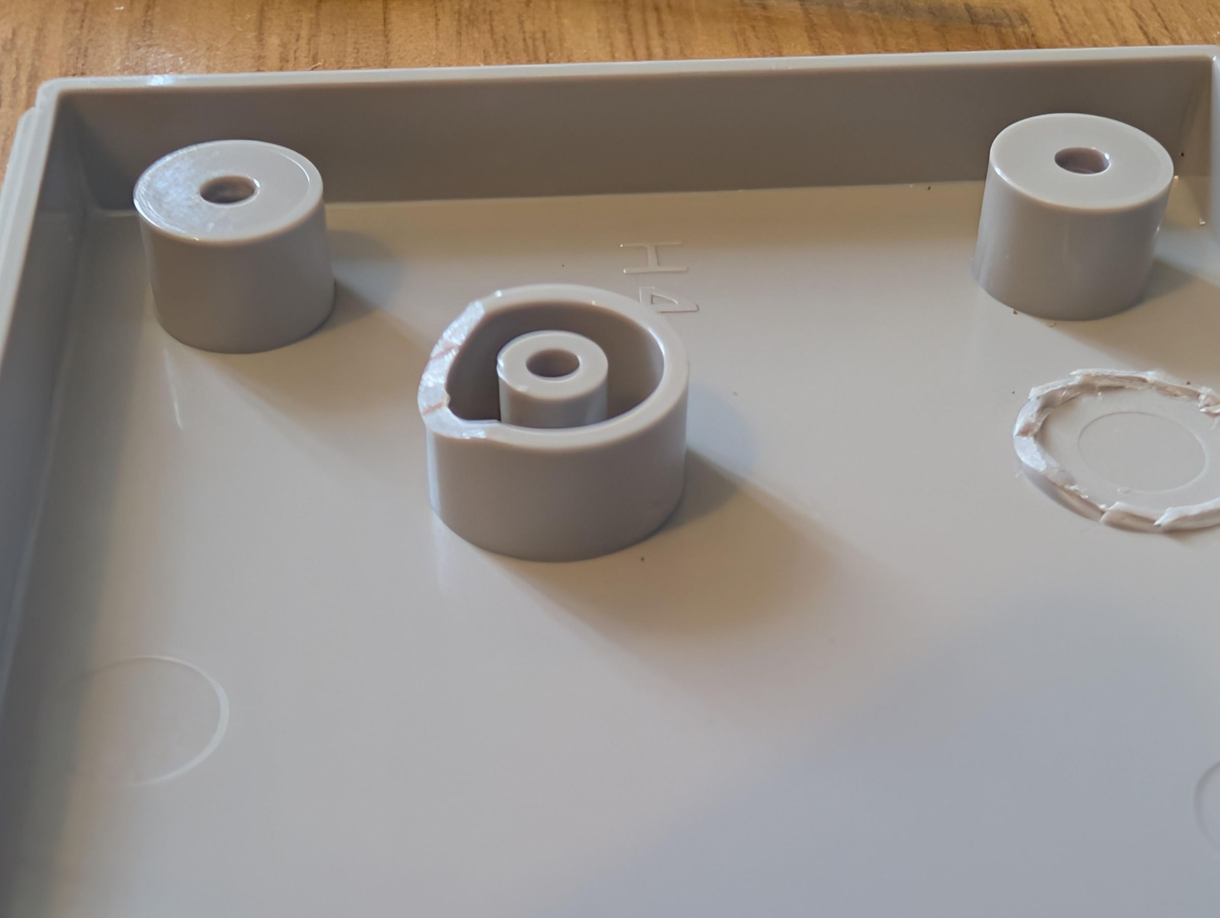
This is based on an aftermarket shell but an original shell very similar.
I didnt take many pictures while actually cutting the shell as I wasnt totally sure what I needed to cut away so I offered up the PCB to the shell, marked up where I needed to cut or snipped away any lugs and then I cut away slowly, taking as little away as possible while continuing to offer up the PCB each time. There is a not a massive amount of cutting required, mostly the USBC port and the SD slot but you do need to trim some material around the AV port so it sits flush.
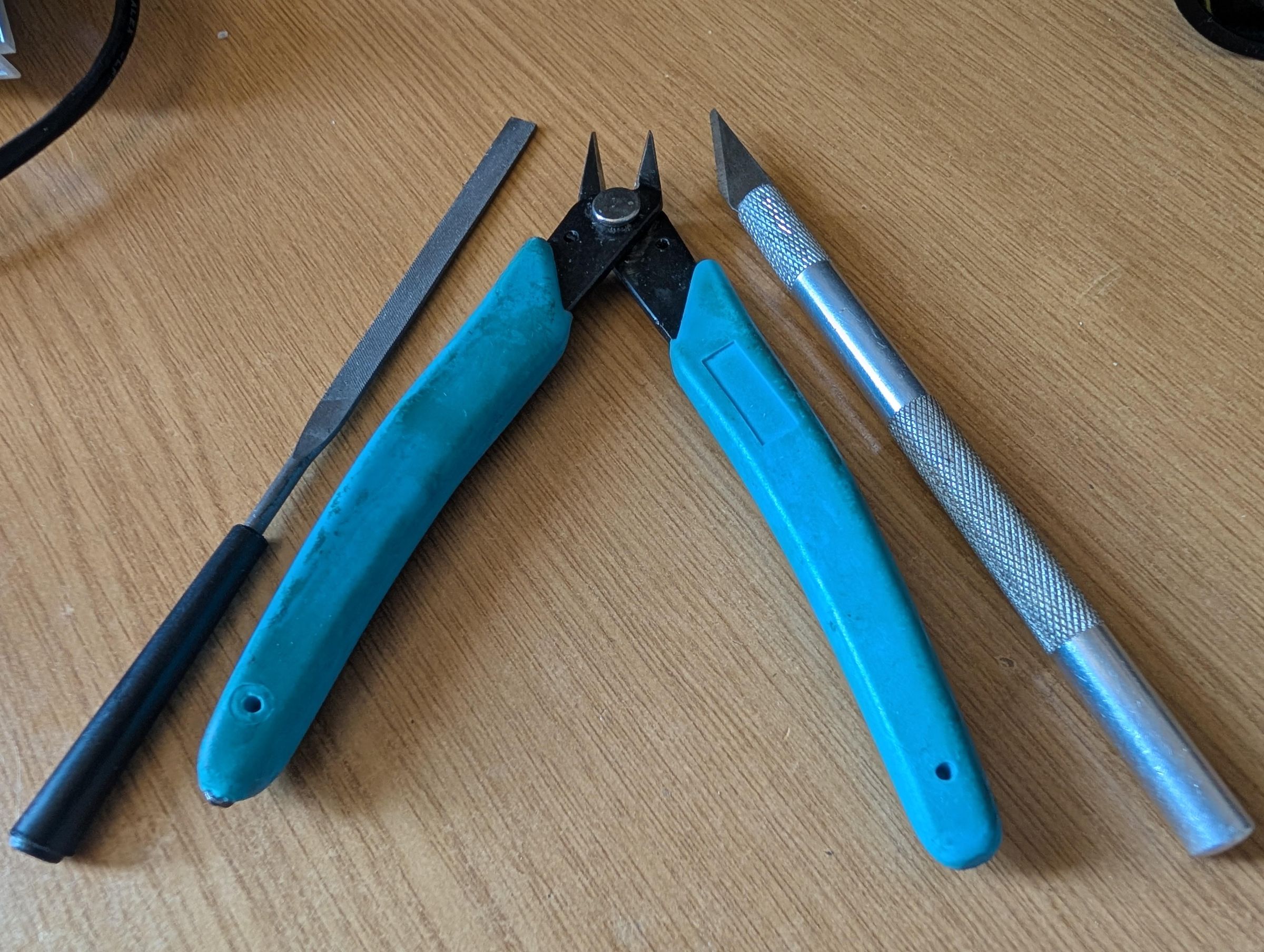
I only used 3 tools - a hobby knife, some side cutters and a file. To be honest, the hobby knife did 90% of the work, I found it worked very well at slicing through the plastic and left very clean cuts. However there are dangers to cutting yourself with a sharp knife, you can also use a multitool with some grinding attachments and a file to clean up. I would be wary of using the side cutters around the USBC and SD slot, I found it scared/bent the plastic. The side cutters worked great at removing internal lugs and I used the file to tidy up some edges.
One last thing to note, just incase its not obvious by the pictures. You do need to slightly trim the DPad support (the one on the back shell) just the bottom 30-50% so it clears the MicroSD slot on the PCB.
Programming the ESP32
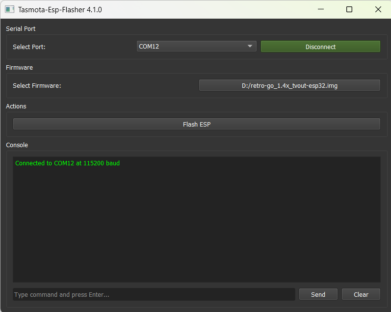
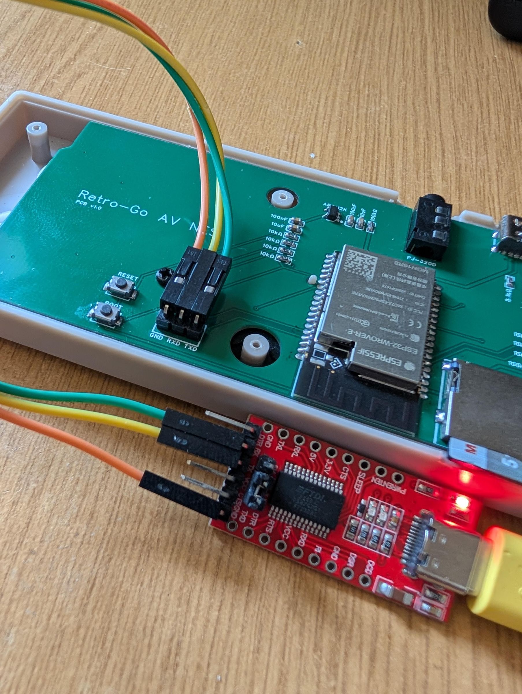
The ESP32 has no onboard programmer, so thats where the USB Programmer comes in. Theres a 3 pin header on the PCB marked GND, RX & TX, this is the programme port, solder a 90degree header to this (or you can just solder wires directly if you want)
The USB Programmer also has a GND, RX and TX, note that you need to connect RX>TX and TX>RX between the PCB and Programmer. Also set the Programmer to 3.3v via the jumper.
I recommend using ESP-Flasher to flash the ESP32, you need to download the firmware image HERE, theres a PAL and NTSC version, I recommend the NTSC if your setup supports it, save it somewhere and locate it in ESP-Flasher, connect the USB Programmer to your PC, it should pick up as a COM Port.
You need to get the PCB/ESP32 into flash mode, you just need to hold the 'BOOT' button while plugging in the USBC port (the USBC port on the PCB), this will put the ESP32 into flash mode and now assuming the 3 wires are connected between the PCB and the USB Programmer, you can just click 'Flash ESP' and it will start the flashing process.
If it gives an error, most likely the ESP32 isnt in flash mode, just unplug the PCB, rehold the BOOT button and plug in, keep it held in for a second or two after plugging in the PCB. Try again. It can take a few tries, if you then get an error about the COM Port, just unplug and replug in the USB Programmer.
Setup Retro-Go & SD
Retro-Go itself is quite easy to use, it has a very simple launcher with all of the nice stuff like boxart, save states etc. It doesnt include any games/roms etc but I will link the SD structure below, which you can copy to your SD card to make it easier it know where all your games/roms go, plus I have made a few changes to some emulators for visual or performance improvements.
You dont need a very large SD card, all of the supported systems have very small rom files, something like a 4GB will be more than enough.
Format a SD card to FAT32. Download the SD structure HERE, extract and copy the files over to your SD card.
Add your games e.g. your NES games go into roms/nes, Gameboy into roms/gb. They can be zipped or unzipped, but note that the boxart will not show when using zipped roms as it relies on the roms CRC32 files. It isnt like we're struggling for space, so unzipped will be better :)
Also note that to access the menu system both in the launcher and in game, you need to press both START & SELECT together. This allows you to then save (savestate) and/or exit as well as some other Retro-Go options.
Enjoy Retro Gaming on a Retro TV
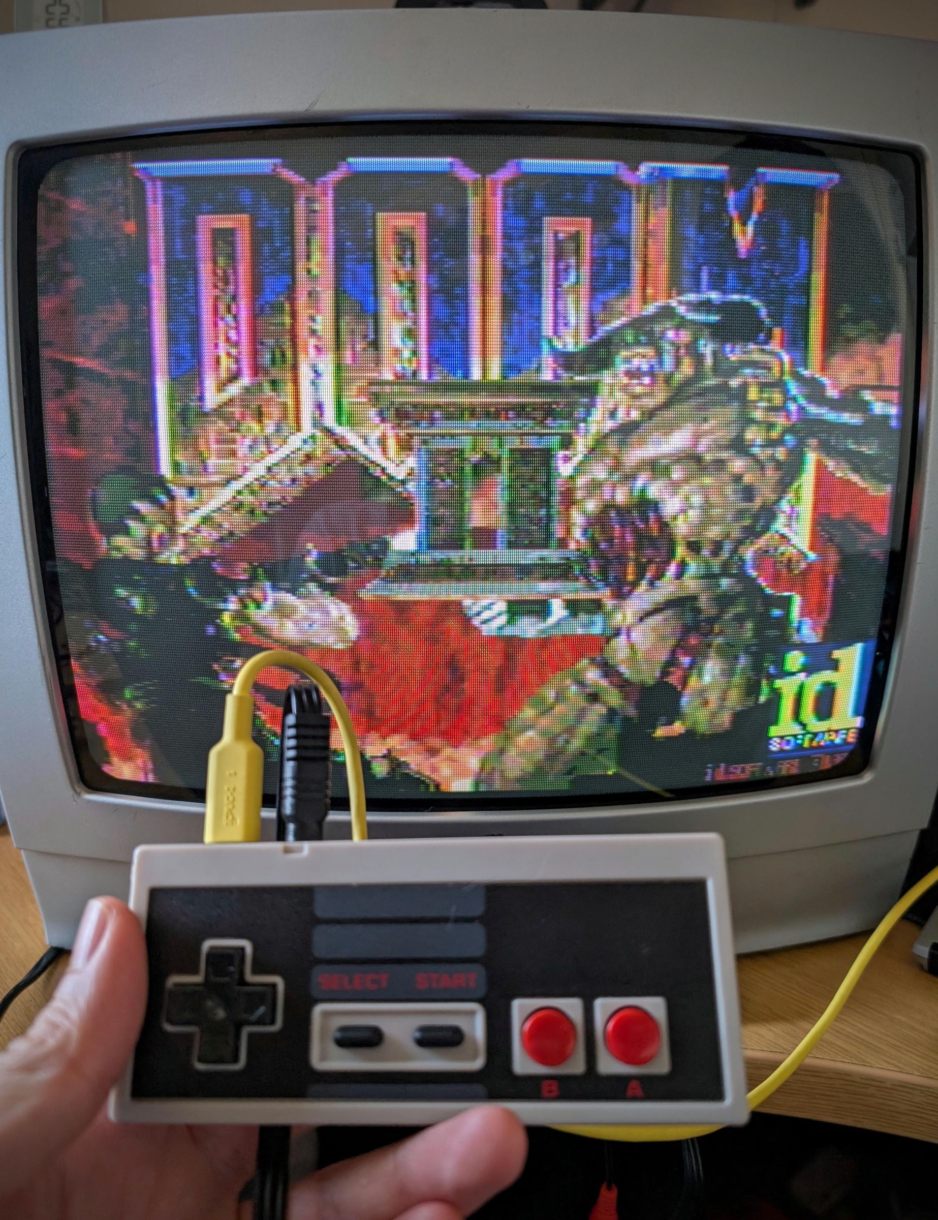
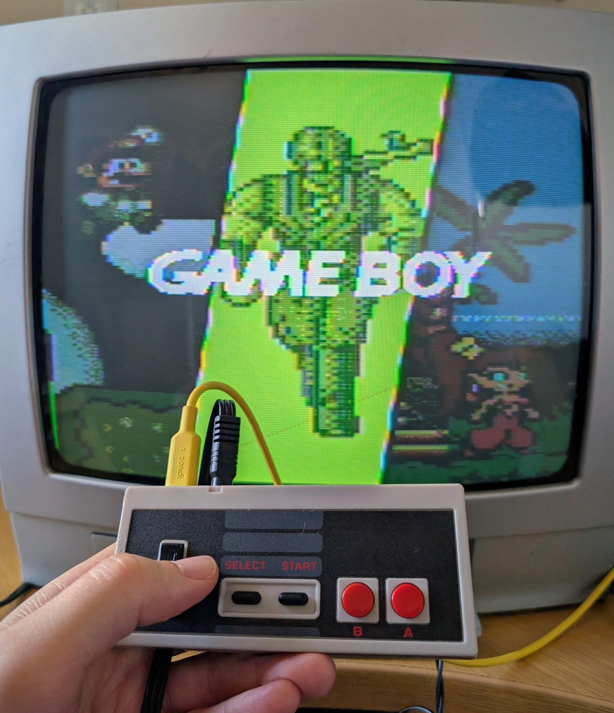
I am not entirely sure if a device that outputs to composite is of any use in 2026 but I enjoyed making it, so may as well share.
However if you have a CRT TV and enjoy the possibility of playing some retro games on a CRT TV, then this isnt the worst device.
Note that sometimes theres some rolling lines on the far left in the menu, this happens sometimes but only in the launcher and never in game. I have not got to the bottom of that issue yet since as only happens sometimes and never in game, its a tricky one to track down.
PAL does work, but PAL has a larger overhead therefore does come at a further performance penalty, I recommend using NTSC if your setup allows.
Last Step? Amend Firmware, Different Modes, PAL?
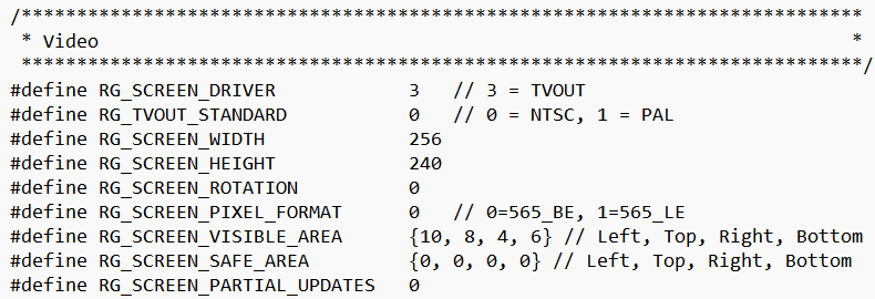
The last step is only for people that want to amend and build the firmware themselves. The reason I mention it, is because I have manually amended the overscan to suit my TV, I dont have lots of CRT TV's to try this on and my TV (as you can see from the pictures) is just a basic CRT, it doesnt have any image over/underscan options.
Its very possible my TV is way off and doesnt suit. If more than one person actually builds one and turns out its wayyy off, I am happy to adjust the original firmware image but others can also make small amendments and rebuild the firmware.
Its pretty easy to download, amend and rebuild the firmware. This isnt going to be exhaustive guide, but I'll give some basic tips below based on my experience with Windows!
- Download/install ESP-IDF v5.5.1 - Windows installer is HERE
- Start ESP-IDF environment via the command prompt desktop link
- Download/Git Clone the repo with command: git clone -b tvout https://github.com/DynaMight1124/retro-go
- Make amendments to the config.h in components\retro-go\targets\tvout-esp32
- Build using: python rg_tool.py --target tvout-esp32 release --no-networking
- Flash image and test
So what could you change? Firstly 'VISIBLE_AREA' you will see from the above screenshot, I have tailored these to match my TV... which I am assuming/hoping is similar to a lot of TV's! If not you can adjust, rebuild/flash and test. You can also change between PAL and NTSC.
You could also amend the resolution. I personally found 256x240 a good compromise for display size and performance but you could try 320x240 or 256x224. The driver will always scale, so it fills the TV but resolution changes do change aspect for some systems.
If you're an experienced programmer, theres the tvout & snd drivers in components\retro-go\drivers happy for any pull requests with improvements, especially around performance optimisations!