Navigating 3D Heights: a STEM Exploration of Contour Maps With Fusion 360 and TinkerCAD
by Stability_2416 in Teachers > 11
498 Views, 3 Favorites, 0 Comments
Navigating 3D Heights: a STEM Exploration of Contour Maps With Fusion 360 and TinkerCAD
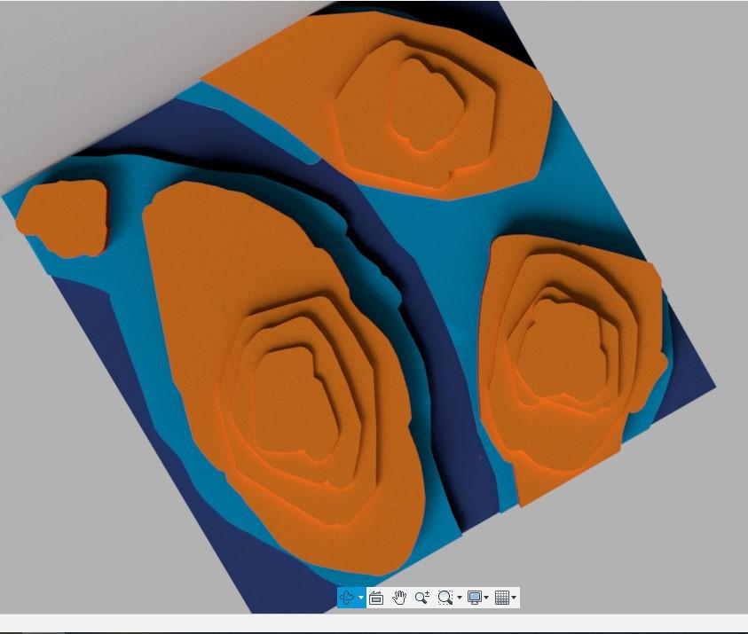

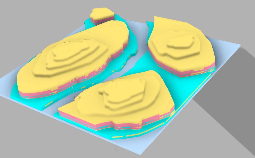

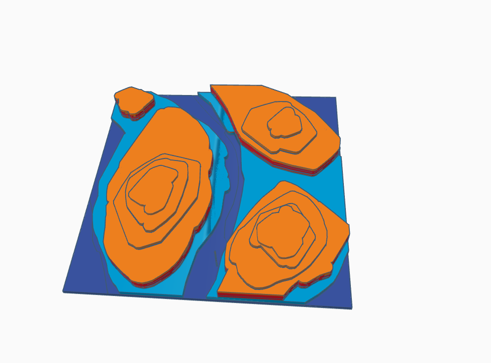
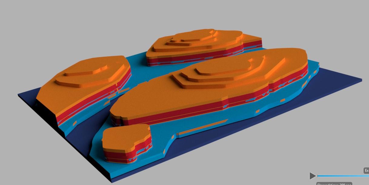
Exploring Contour Maps in STEM Education using Fusion 360 and Tinkercad
Have you ever wondered how scientists, engineers, and environmentalists unveil the secrets hidden within landscapes, deciphering the language of elevation and terrain? Imagine having the power to visualize the undulating contours of mountains, valleys, and plains, unraveling the intricate patterns that shape our world. So in today's Instructables, I'm going to share how you can make one for your classroom, also I have shared the STL file, so if you wish to 3D print this model for your classroom please go ahead : D But first, you might wonder What are Contour Maps and their significance.
Contour maps serve as a visual representation of the topography of a given area, depicting variations in elevation through contour lines. These maps are invaluable tools in fields ranging from geology and geography to environmental science and civil engineering. Understanding contour maps aids students in developing spatial reasoning skills, honing their ability to interpret complex data, and fostering a deeper appreciation for the interconnectedness of various STEM disciplines. Moreover, When you analyze a contour map it can help you to understand the characteristics of a country's ground surface. Thus, the potential communication route between various locations can be identified.
Benefits of this project:
Real-world Application: Fusion 360 provides students with a professional-grade platform commonly used in industries for product design and engineering. Tinkercad, on the other hand, offers a user-friendly entry point into 3D design. Integrating these tools allows students to bridge the gap between theoretical concepts and real-world applications.
Hands-on Learning: By creating contour maps in a virtual environment, students can manipulate and visualize geographical data in three dimensions. This hands-on approach not only reinforces theoretical concepts but also cultivates problem-solving skills as students navigate the challenges of transforming abstract ideas into tangible 3D models
Project Overview:
In this project, students will explore the fundamentals of contour maps, gaining insights into the representation of elevation data and its applications in various STEM fields. Using Fusion 360 and Tinkercad, they will translate their theoretical knowledge into practical skills by designing and creating 3D models of contour maps. This hands-on experience will not only enhance their technical proficiency but also instill a deeper understanding of the real-world implications of contour mapping.
My Background -
I'm a STEM Educator in the Baldwin Highschool, PA
Downloads
Supplies
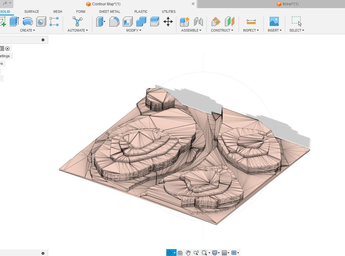
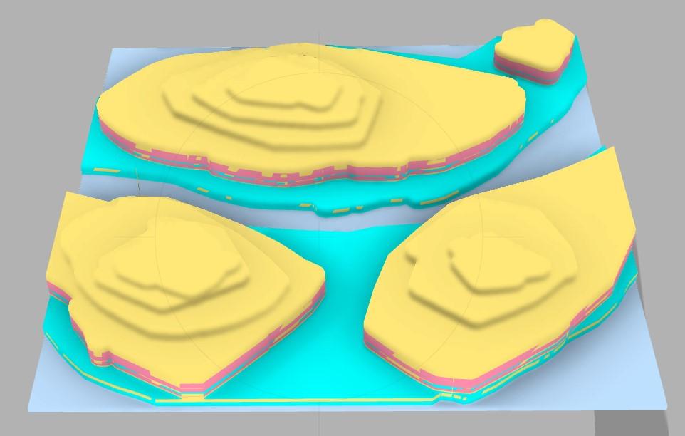
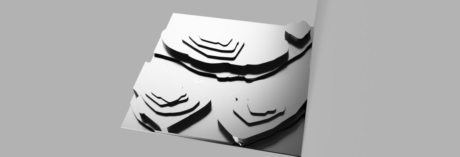
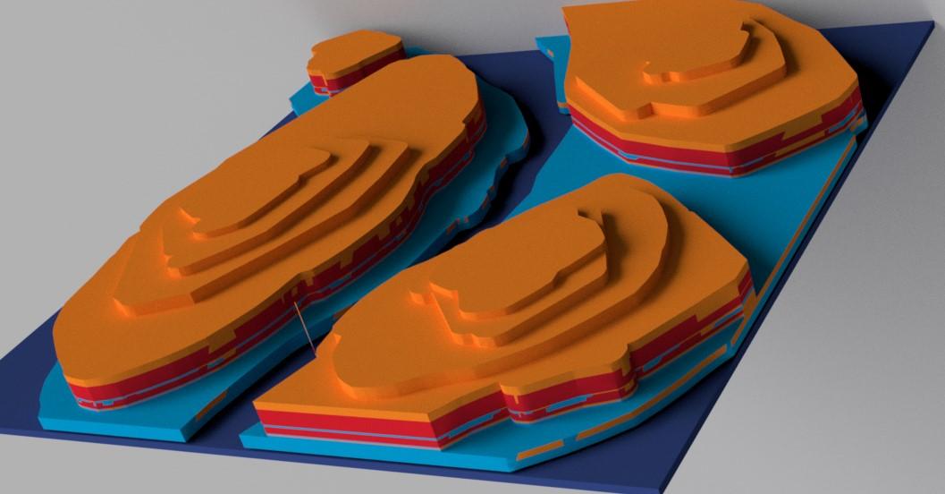
- Computer Access
- Download and install Fusion 360, a professional 3D CAD software, on your computer.
- Access Tinkercad through a web browser for intuitive online 3D design.
- 3D Printer
Sketch the Base
.jpg)

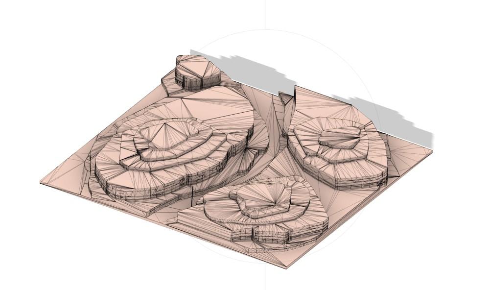
- Use Fusion 360's sketching tools to create a base layer. This initial sketch should outline the general shape and geographical features of the landscape.
- Consider using reference images or existing maps to guide the creation of the base sketch.
Import Elevation Data (Optional)
.jpg)


- If you have elevation data, import it into Fusion 360. This step helps align your contour lines with the actual topography, ensuring accuracy in your representation.
- Fusion 360 supports various file formats for importing geographical data.
Draw Contour Lines

.jpg)

- Begin drawing contour lines on the base sketch. Use Fusion 360's drawing tools to create smooth and accurate contours.
- Consider the contour interval, or the difference in elevation between each line, based on your project requirements.
Set Extrusion Heights
.jpg)
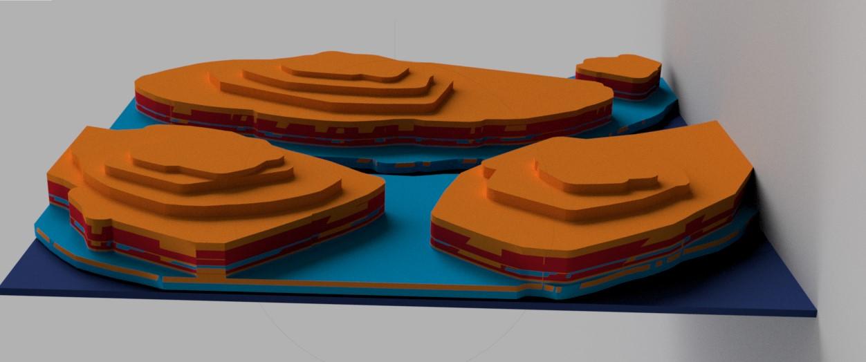
- Assign extrusion heights to each contour line based on the corresponding elevation data. This step transforms your 2D sketch into a 3D representation of the terrain.
- Adjust the height of each contour layer according to the actual elevation values.
Review and Adjust
.jpg)
.JPG)
.jpg)
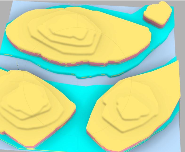
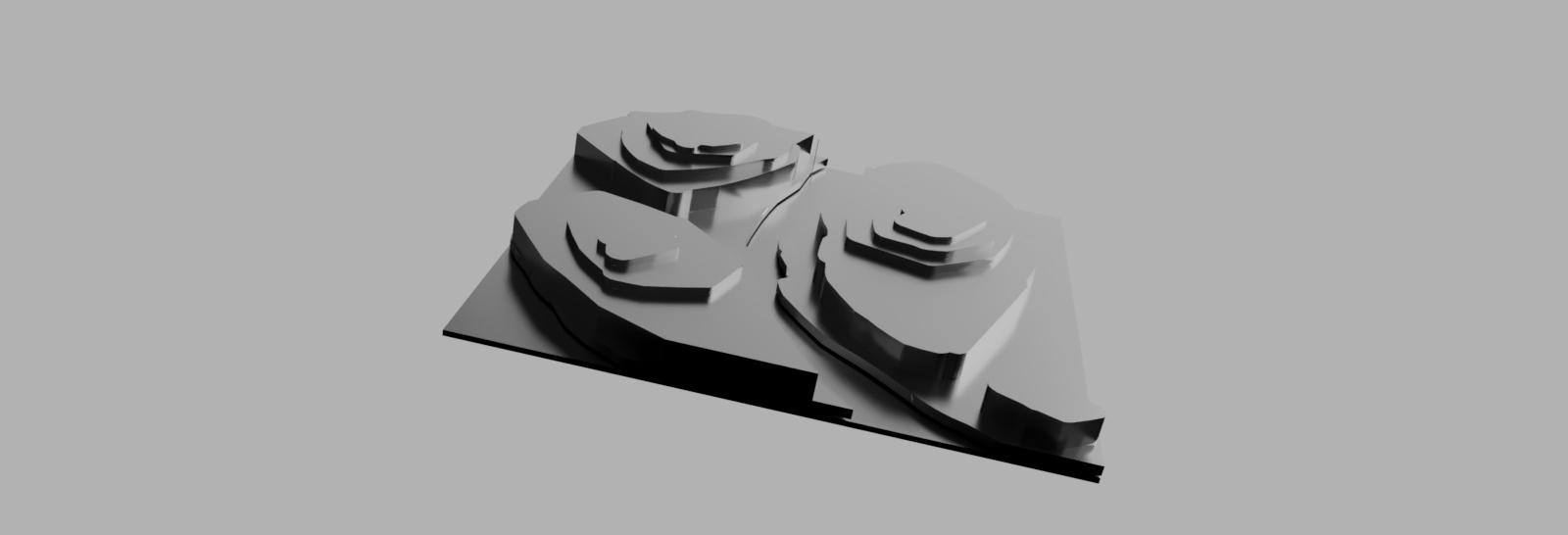
- Carefully review the initial layer, ensuring that contour lines align with the intended geographical features.
- Adjust extrusion heights and sketch details as needed. This step is crucial for accuracy in representing the topography
Smooth Transitions & Render
.JPG)
.jpg)
.jpg)
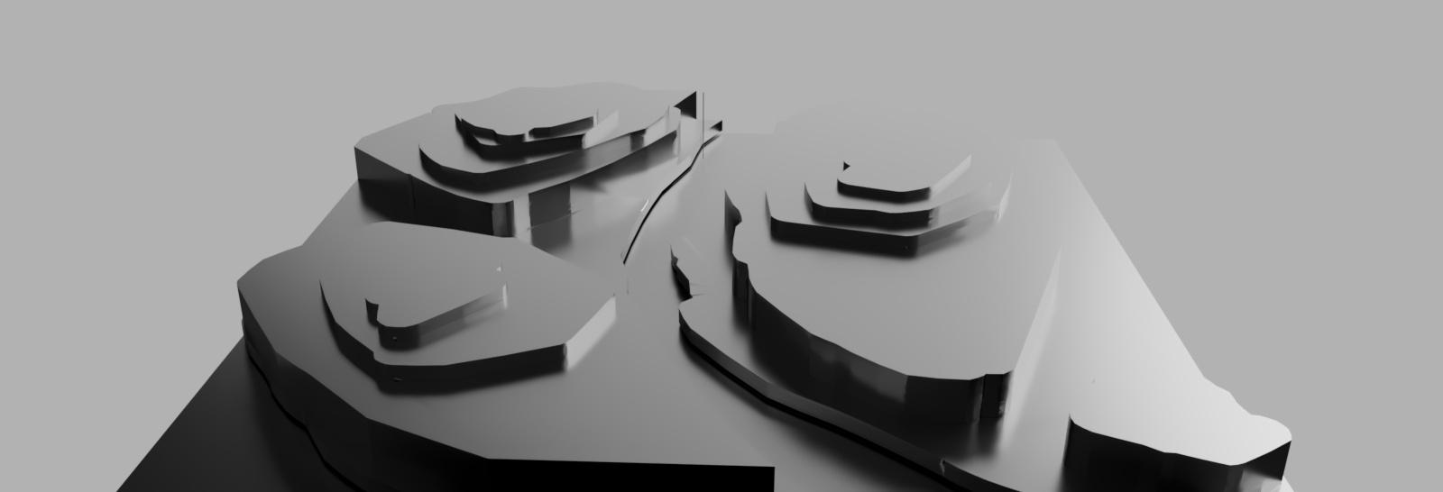
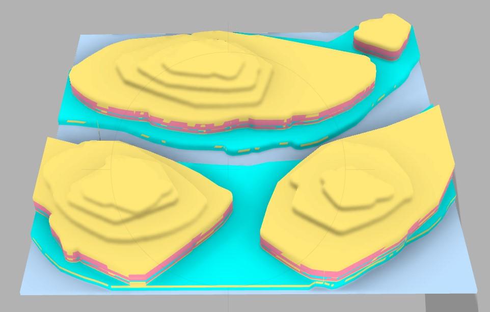
- Utilize Fusion 360's sculpting tools to smooth transitions between contour levels. This enhances the visual appeal of your map and provides a more realistic representation of the terrain.
- Focus on creating natural slopes and transitions between elevation changes.
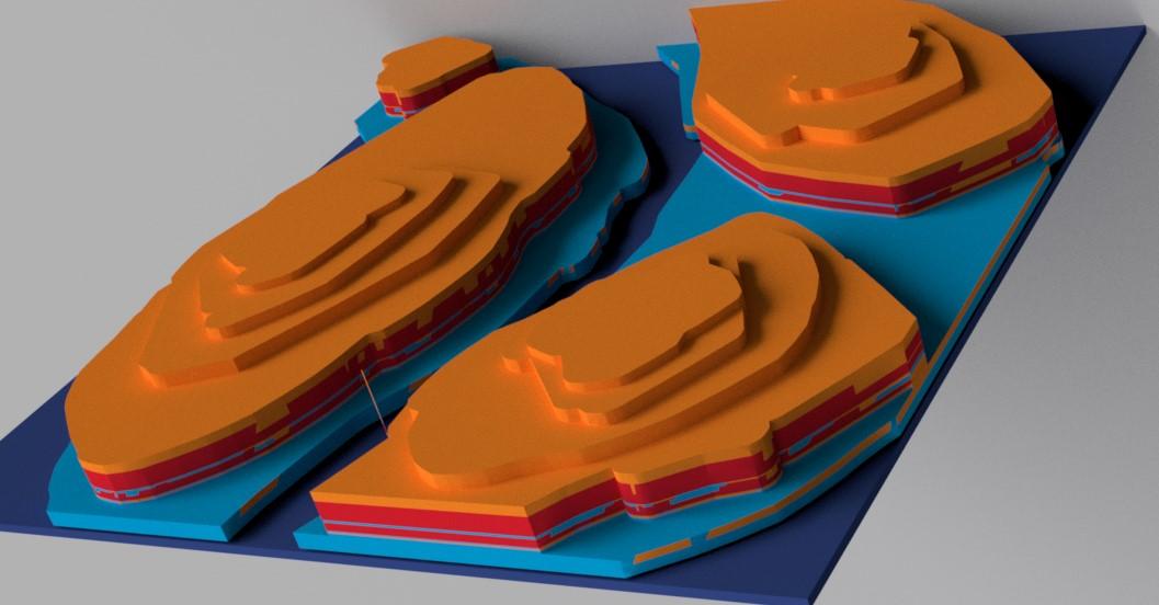
- Enter the rendering workspace in Fusion 360 to add realism to your model. The rendering workspace allows you to simulate how your contour map will look in different environments and lighting conditions.
- Apply materials to the contours, considering the color gradients that represent elevation changes. Experiment with textures and surface finishes to enhance the visual appeal.
- Adjust the lighting in the rendering environment to cast shadows realistically. This step provides a preview of how your 3D contour map will appear when fully rendered.
- Use the rendering tools to create high-quality images or animations that showcase the details of your map. This step is essential for visualizing the final output and making informed decisions about any necessary adjustments.
Incorporate Features
.jpg)
.jpg)
.jpg)
- Enhance your initial layer by adding features such as rivers, roads, or specific landmarks. Use Fusion 360's design tools to create these additional elements.
- Consider the impact of these features on the overall appearance and functionality of your contour map
Save and Export
.jpg)
.jpg)
.jpg)
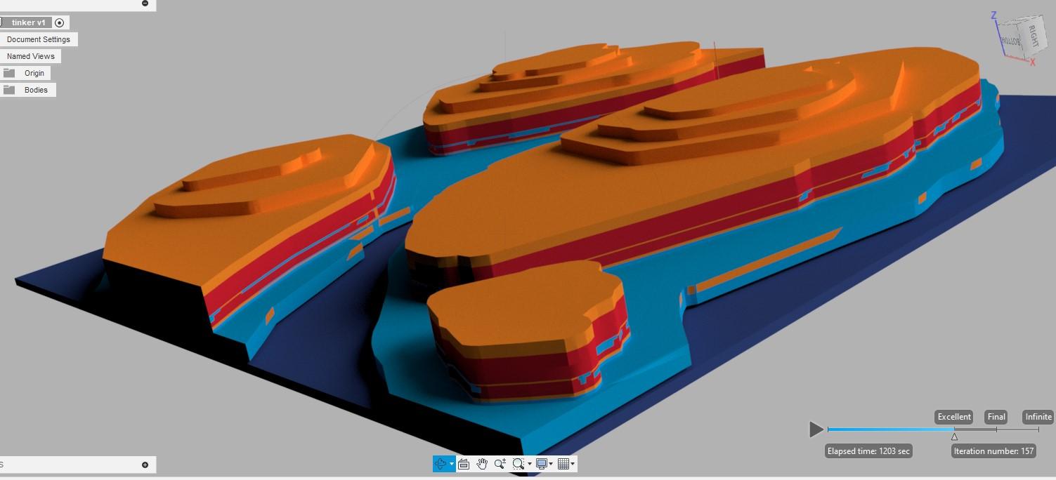
- Save your progress within Fusion 360 to ensure that your work is preserved. Periodically save your project to avoid data loss.
- Export the completed initial layer as an STL file. This file format is widely used and compatible with most 3D printing software.