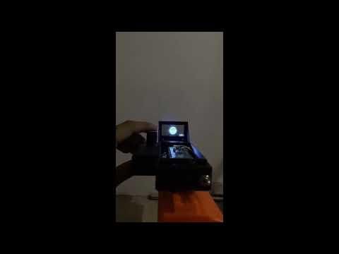
Nerf Gun TOLED Scope : Pi Pico 2 Based Adjustable Aim Sight
by Areeeeen in Circuits > Raspberry Pi
151 Views, 1 Favorites, 0 Comments
Nerf Gun TOLED Scope : Pi Pico 2 Based Adjustable Aim Sight
I am Areen Phaltankar, studying in 12th grade in Pune, Maharashtra, India
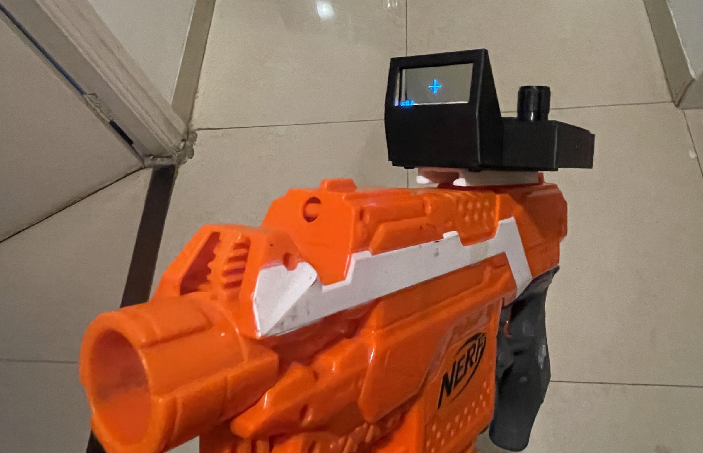
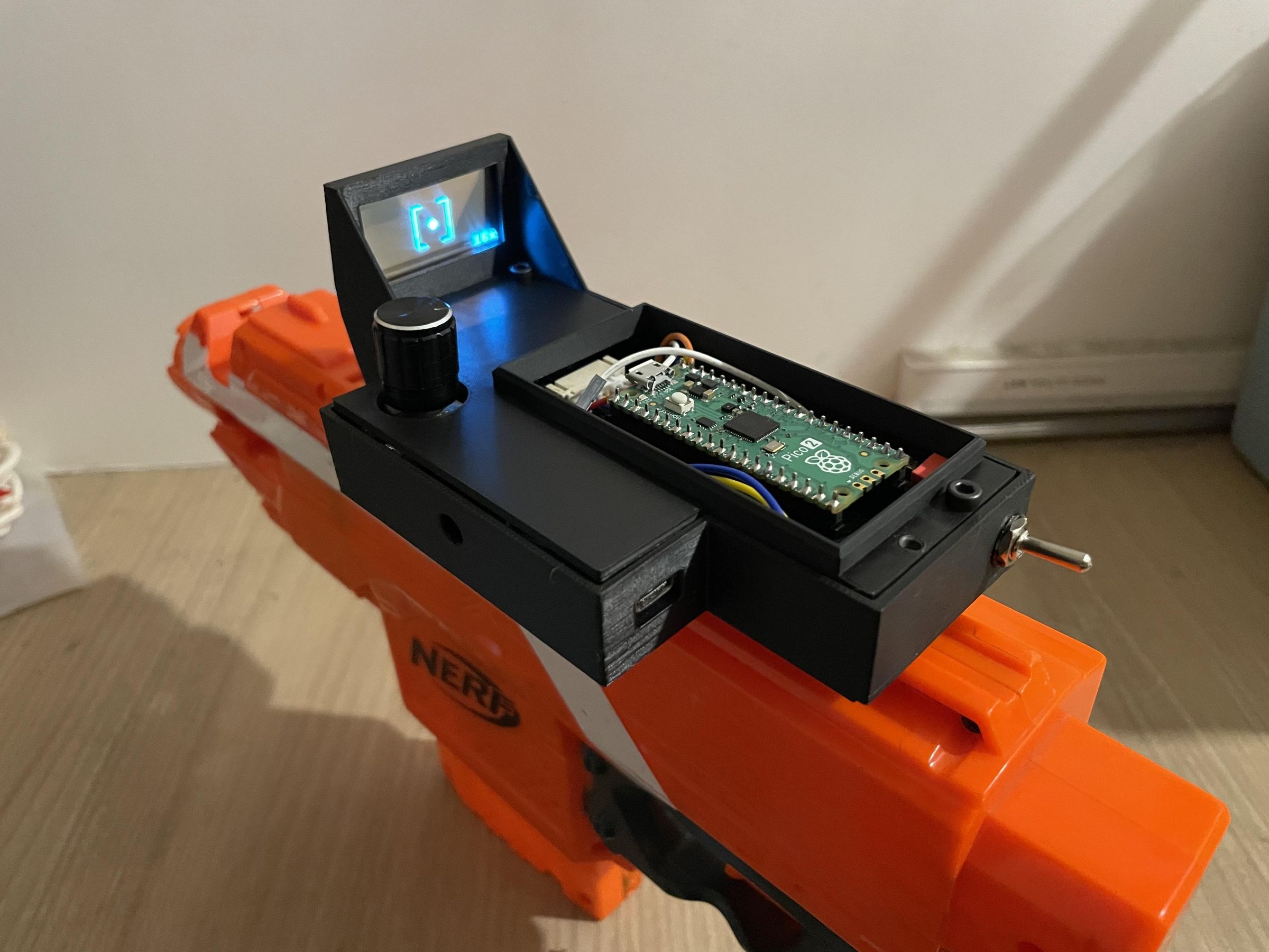
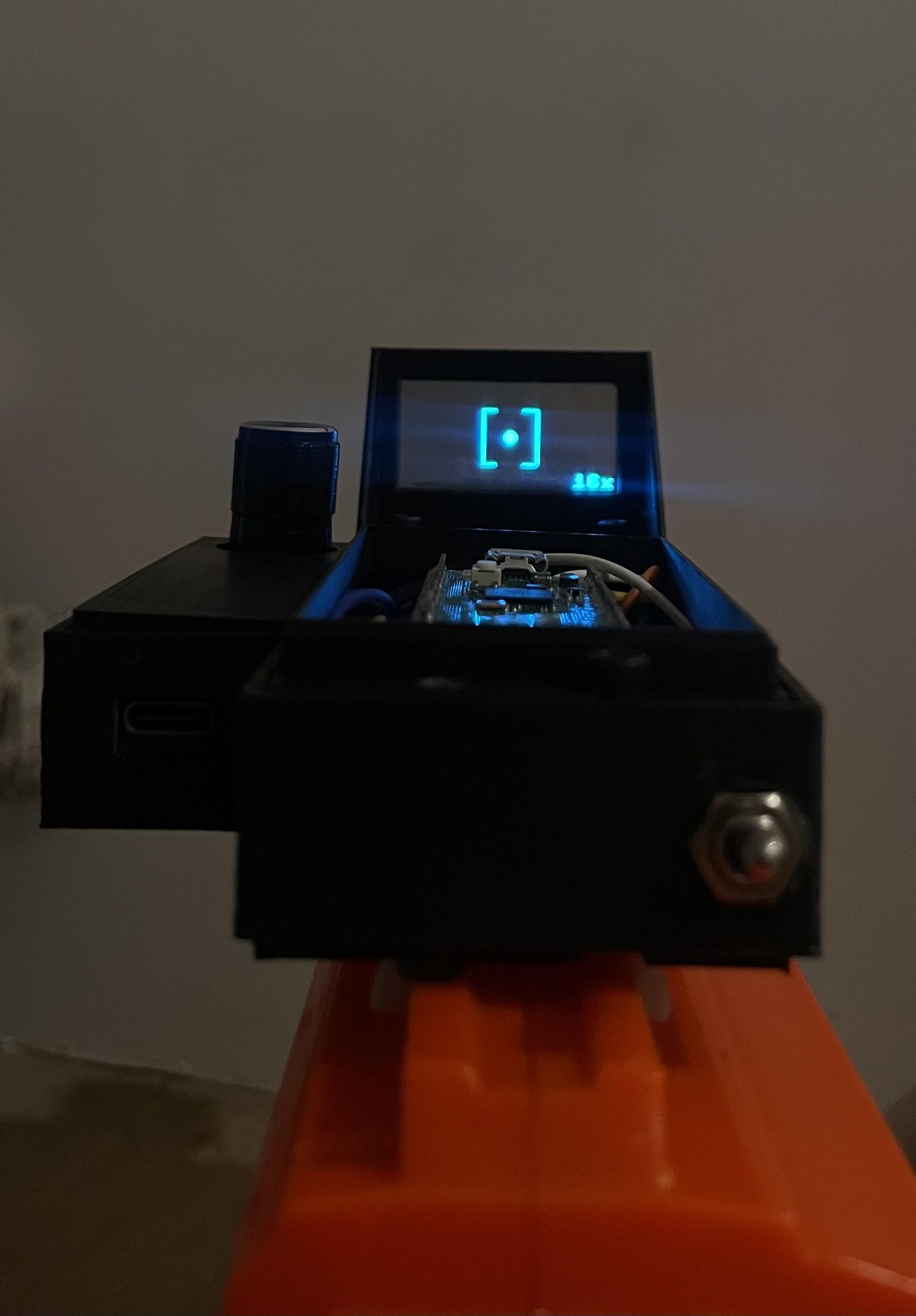
Partially inspired by the new extraction shooter game 'Marathon', I set out to make a futuristic scope for my nerf gun. The Raspberry Pi Pico offers the perfect platform to develop this project along with the Waveshare TOLED (Transparent OLED) I bought for this project. This Instructable shows my process of making it and hopefully is a decent guide for anyone who wishes to make one for themselves. Enjoy :)
Features
- 6 crosshair styles: Plus, Dot, Circle, Heart, Cross, and Brackets with dot in the centre
- Cycle through crosshairs - short press of the rotary encoder button
- Adjust crosshair size - rotate the encoder
- Calibration mode for repositioning the crosshair on screen
- Enter calibration with a long press of the button
- Short press toggles between Y-axis and X-axis adjustment
- Rotate encoder to move crosshair up/down (Y) or left/right (X)
- Long press again to exit calibration
- Interrupt-driven rotary encoder for smooth, accurate input with no stutter
The calibration feature is one I don't think I have ever seen being used on a nerf scope before. The idea is that if you notice that the gun is consistently shooting the darts the same angle away from the reticle (crosshair), you can adjust the reticle to offset that difference and great aim would be restored!
Supplies
Electronic Components
- Raspberry Pico 2 (Pico 1 also works) x1
- 1.51 inch Waveshare Transparent OLED x1
- rotary encoder x1
- 3-pin Lever Switch (M6 screw size) x1
- TP4056 USB-C Charging module x1
- 3.7v LiPo Battery x1 (600 mAh used)
- 1x20 Female Pin Headers x2
3D Models (all files attached below)
- Main Body - Scope_Main
- Top - Scope_Top_Open and Scope_Top_Closed
- Bottom - Scope_Bottom
- Rail Attachment - Scope_Rail (Credit to the8bitbyte on printables)
Screws, Nuts and Heated Inserts
- M2 Sized
- Screws - 4mm - x6
- Heated inserts - 4mm - x6
- M3 Sized
- Screws - 4mm - x8
- Heated inserts - 4mm - x8
- M6 sized
- Nut - x1 (for lever switch)
Connectors, Wires and Boards
- 90x70mm Prototype PCB board
- female jumper wire to loose wire x7
- male jumper wire to loose wire x2
- JST connector - 7 pin - 2.54 pitch x1
MISC
- Strong Double-Sided Tape
NOTE:
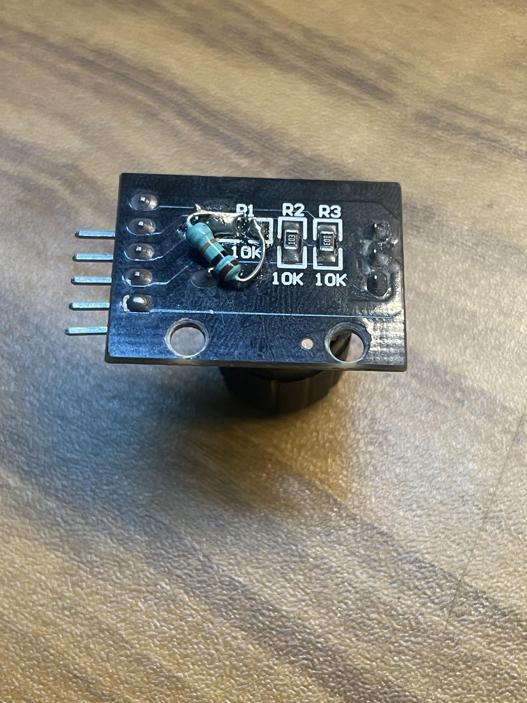
- Make sure there is a resistor on the back of the rotary encoder in the empty component space to enable the use of the button functionality
- Use Strong double sided tape from 3M
Uploading the Code
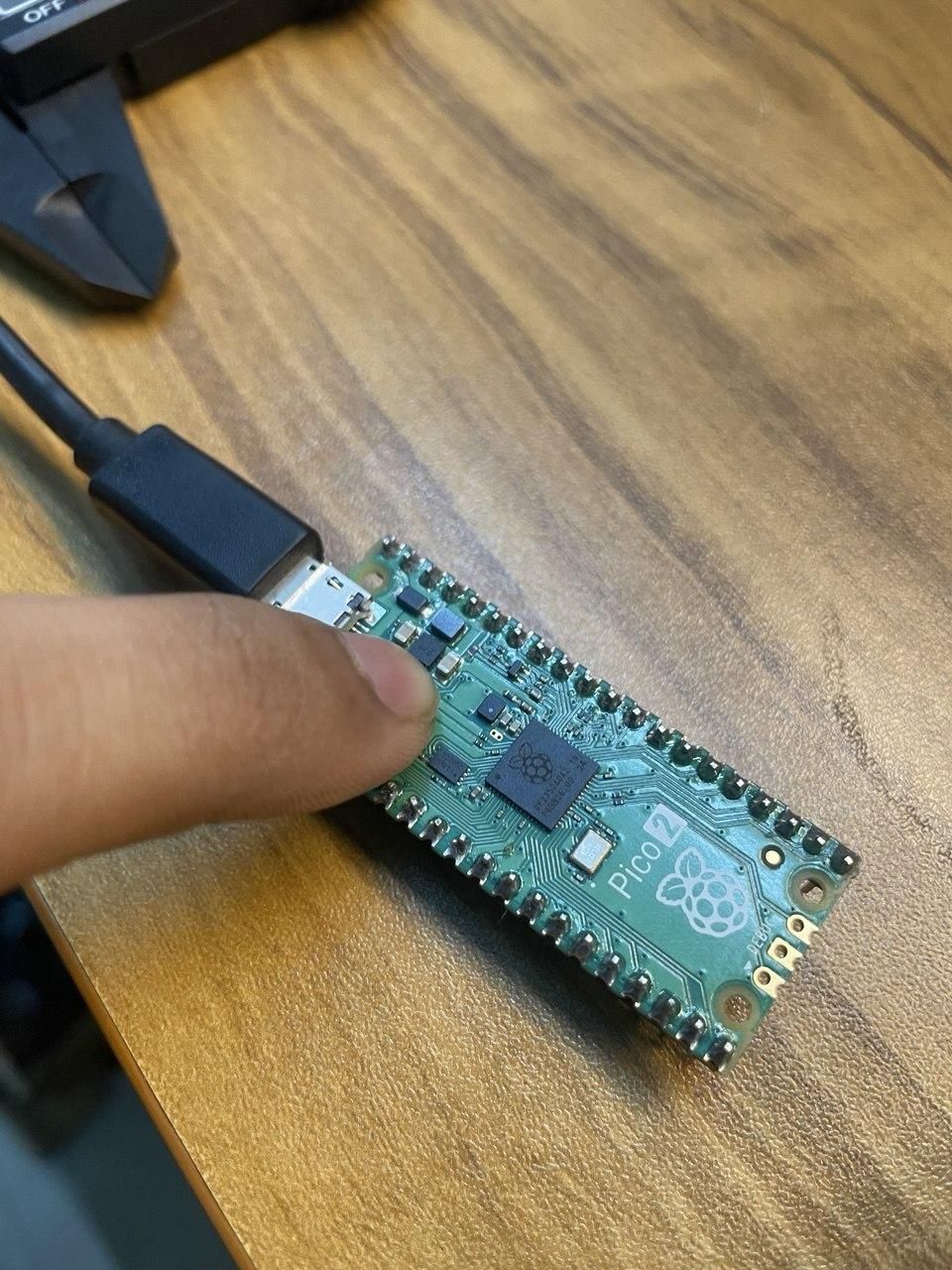
1. Download the Files
Download the following files attached below on this step:
- main.py
- ssd1309.py
Make sure they are saved on your computer
2. Open Thonny
Open Thonny IDE and connect your Pico.
Make sure:
- Interpreter = MicroPython (Raspberry Pi Pico)
3. Upload the Files to the Pico
You need to upload both files:
For each file:
- Open the .py file in Thonny
- Click File -> Save As
- Select Raspberry Pi Pico
- Save the file
Repeat this for all files.
Or refer to https://www.youtube.com/watch?v=3qTxBXVQ4yo&t=61s&pp=ygUldXBsb2FkaW5nIG1pY3JvcHl0aG9uIGNvZGUgdG8gcGkgcGljbw%3D%3D for in depth steps
3D Printed Enclosures
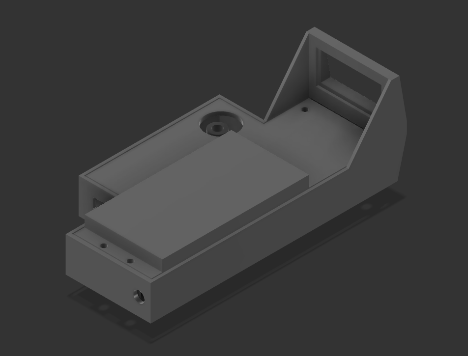
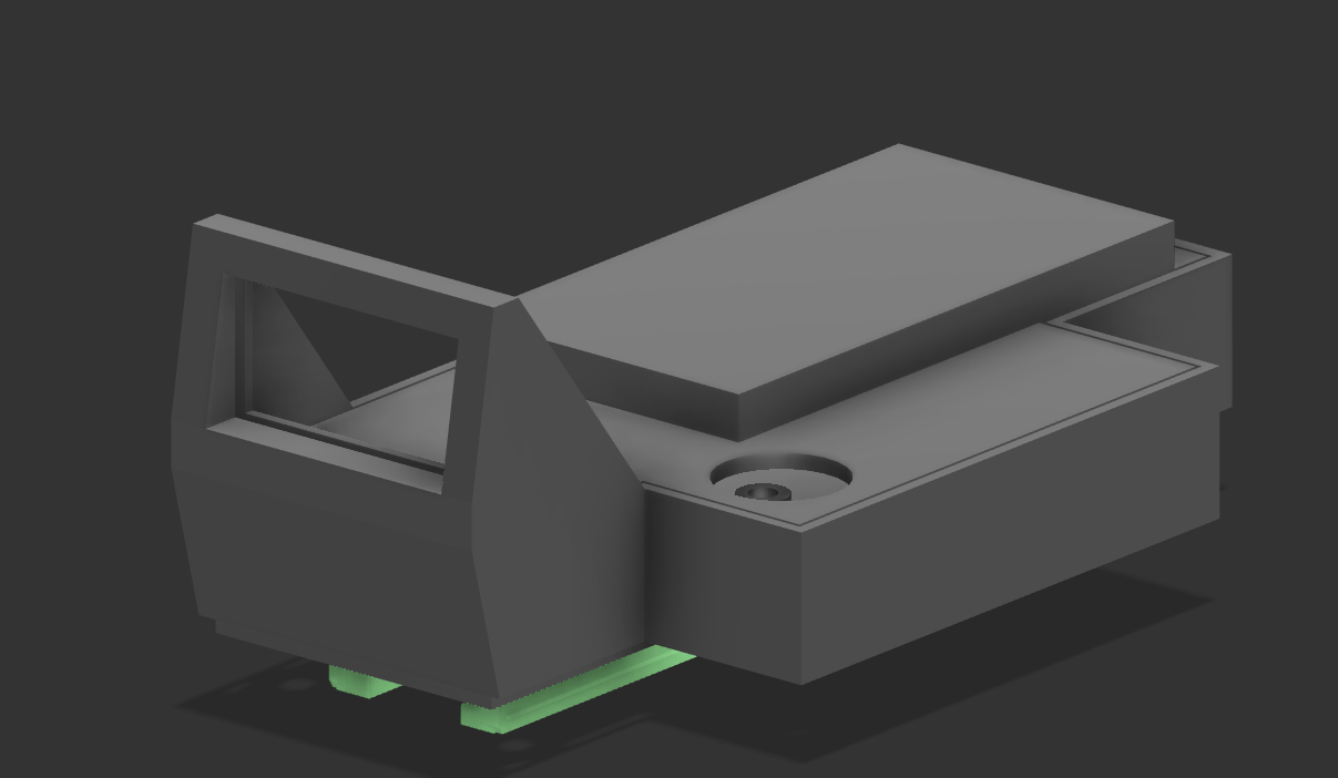
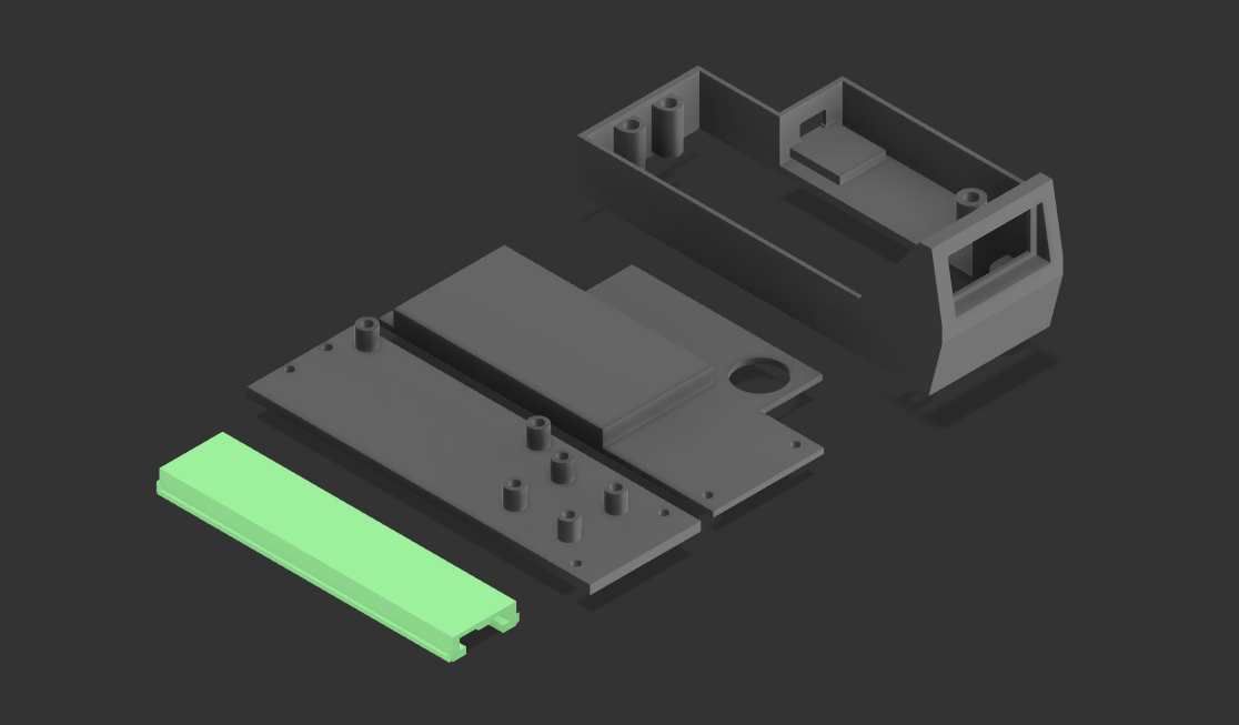
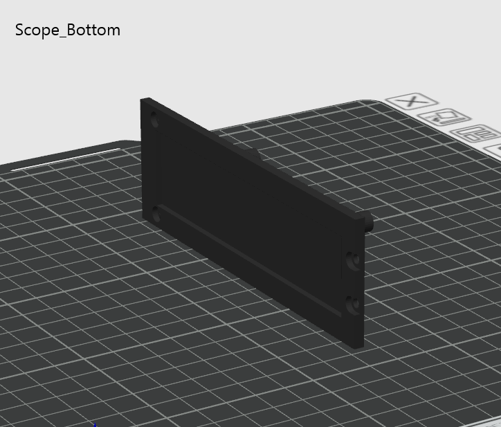
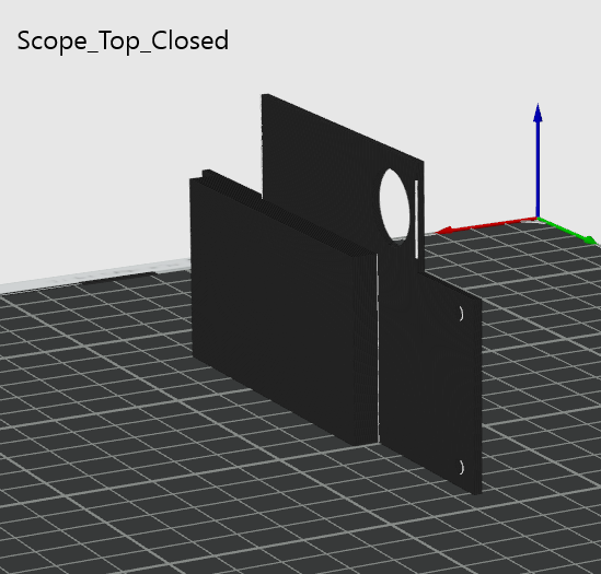
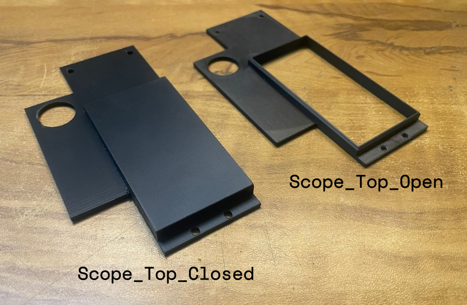
All models are made using Black PLA using 10% infill
(I used White PLA only for the rail because I was out of black filament)
NOTE:
- Print the parts like shown above to minimize support usage when 3d printing.
- In interest of reducing printing time and support material waste, The scope rail should be printed separately from the bottom. Double sided tape should be used to stick them together.
- You can use either Scope_Top_Open which exposes the Circuit inside (the way I like it!) or use Scope_Top_Closed for a minimal and clean look
Attaching the Rail to the Bottom
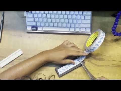
In interest of reducing printing time and support material waste, The scope rail should be printed separately from the bottom. Double sided tape should be used to stick them together.
Make sure the rail is aligned with the groove present in the Scope_Bottom 3d model
Inserting Heat Inserts
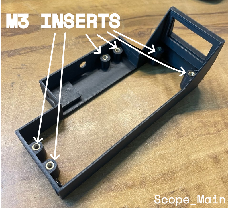
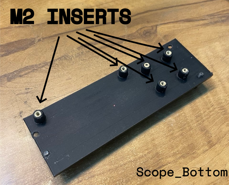
(I forgot to record me inserting them sorry😔)
Cut Perfboard to Desired Size (32x70mm)
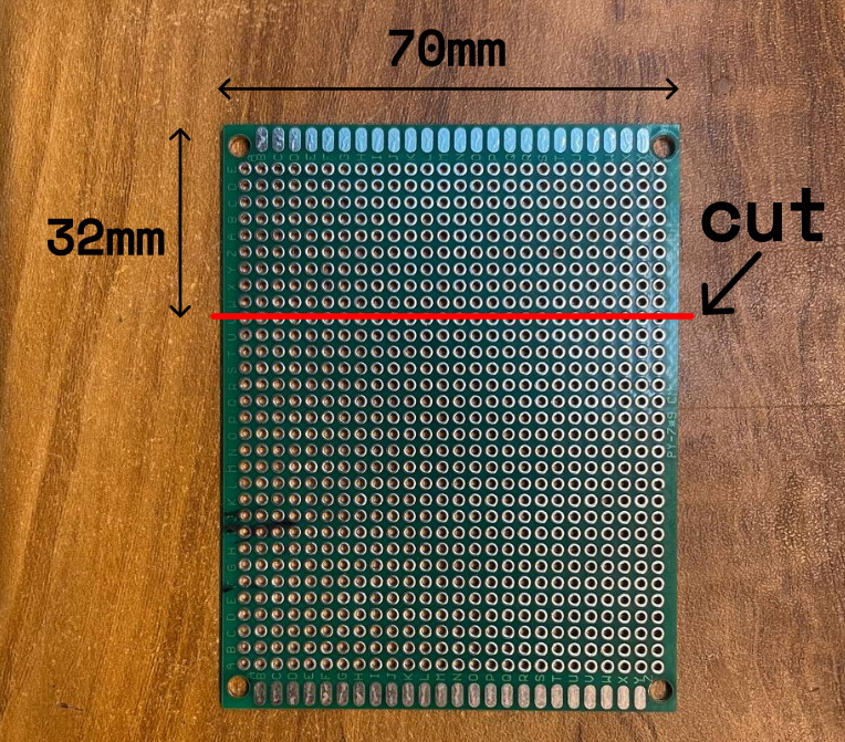
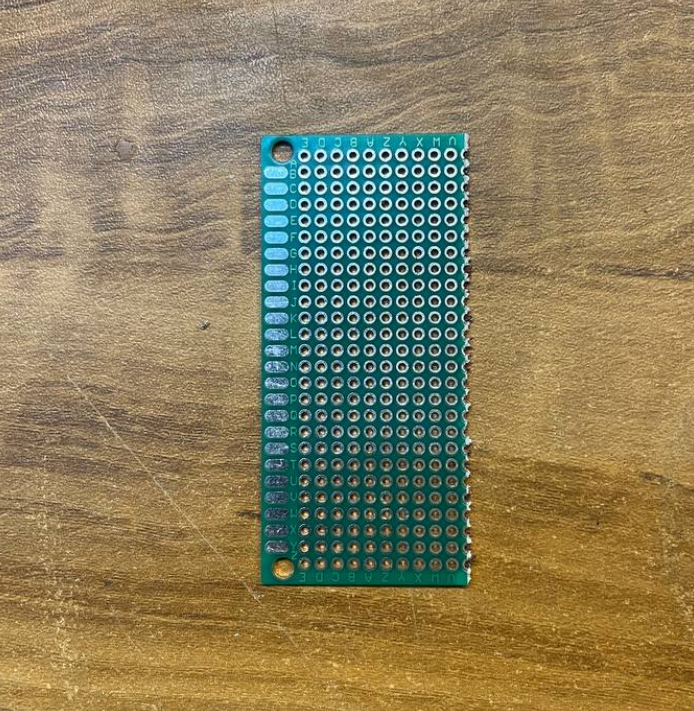
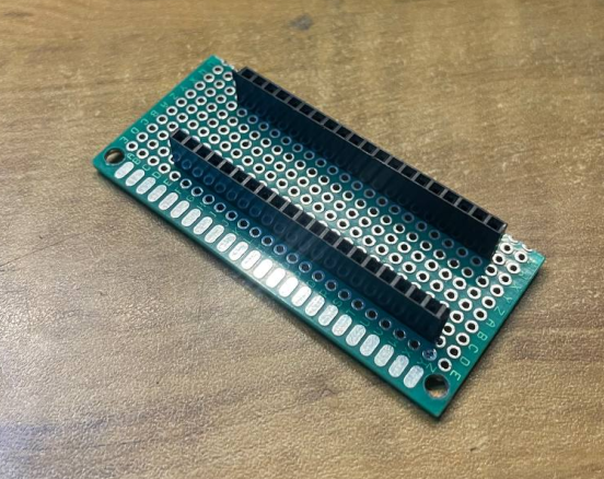
Score the line with a cutter/knife and then snap it with your hands
Wiring the Circuit
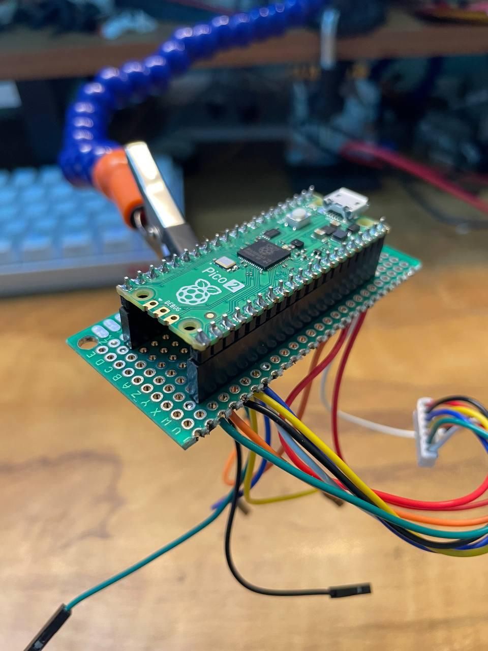
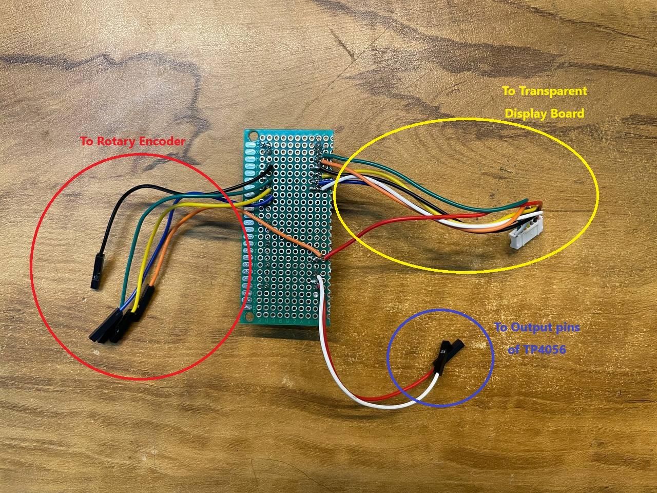
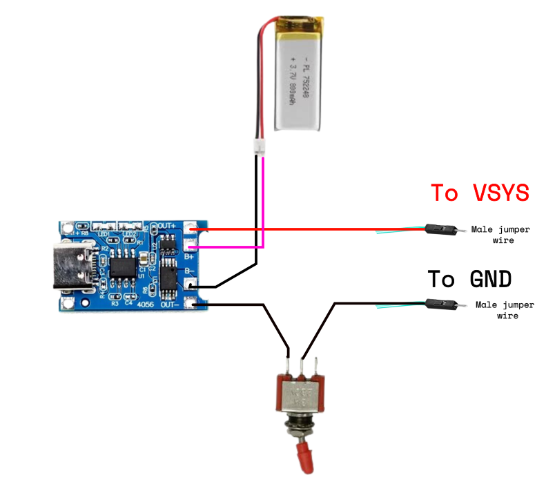
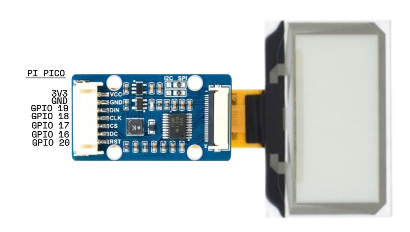
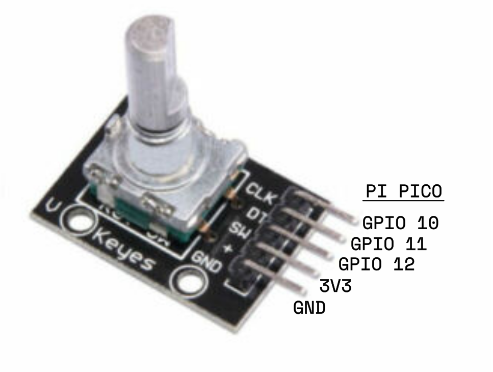
- Mount the Pi Pico 2 to the perfboard using female pin headers
- use the wires shown in the image above for each segment of the circuit
DO NOT connect all separate sectors of the circuit at this step. Keep them in separate groups. It will be much easier to assemble later on.
Tip: Take a photo of the backside of the board after soldering (like the 2nd image above) so that you know which colored wire is connected to which pin on the Pico.
Refer to images above for SCHEMATICS FOR EACH CONNECTION
Assembly

Demo