Nexus — a Tiny IoT Desk Clock
by Next Builder DIY in Circuits > Clocks
6389 Views, 87 Favorites, 0 Comments
Nexus — a Tiny IoT Desk Clock
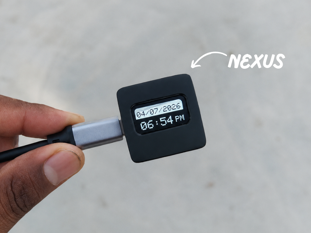
How many times have you picked up your phone just to check the time... only to end up scrolling through notifications or social media for the next few minutes?
It happens to all of us.
While studying or working on electronics projects, I noticed this small habit breaking my focus again and again. I didn't need another smart device with endless features—I just needed something that could show me the time instantly, without any distractions.
That's why I built Nexus. It's a compact Wi-Fi desk clock designed for clean, distraction-free workspaces. Instead of competing for your attention, it quietly sits on your desk, giving you exactly what you need at a glance so you can stay focused on what truly matters.
Whether I'm studying, designing PCBs, writing code, or building my next DIY project, Nexus is always beside me. It's a simple reminder to stay present, keep creating, and make every minute count.
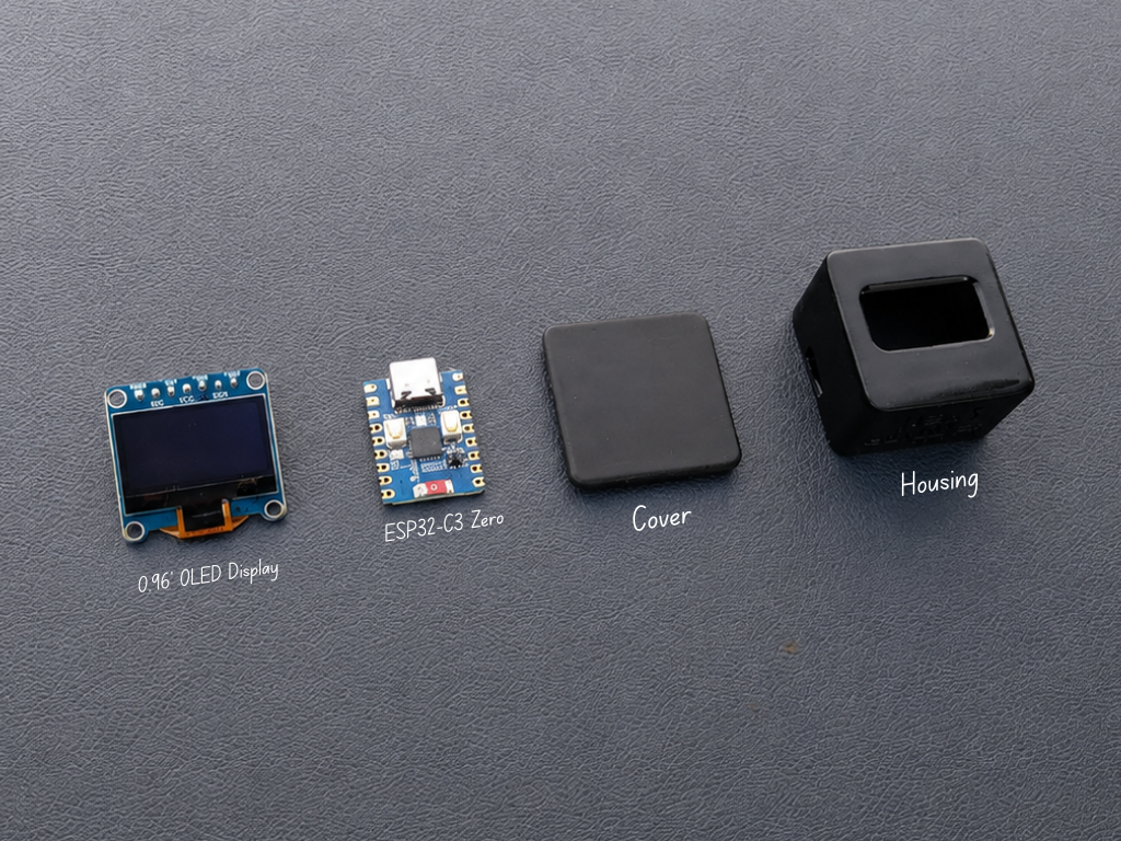
Powered by the Waveshare ESP32-C3, Nexus automatically synchronizes with Network Time Protocol (NTP) servers over Wi-Fi, so it always displays accurate time without the need for a traditional RTC module or manual adjustments.
The crisp Waveshare 0.96-inch OLED display shows the current hour, minutes, AM/PM indicator, and the current date in DD/MM/YYYY format. Everything is housed inside a custom enclosure that I designed from scratch in Autodesk Fusion 360, giving the clock a clean, modern look that fits naturally on any desk.
Sometimes, the simplest devices are the ones that help us stay focused the most.
Supplies
CAD & 3D Printing
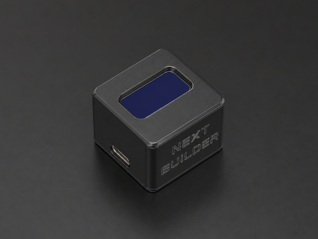
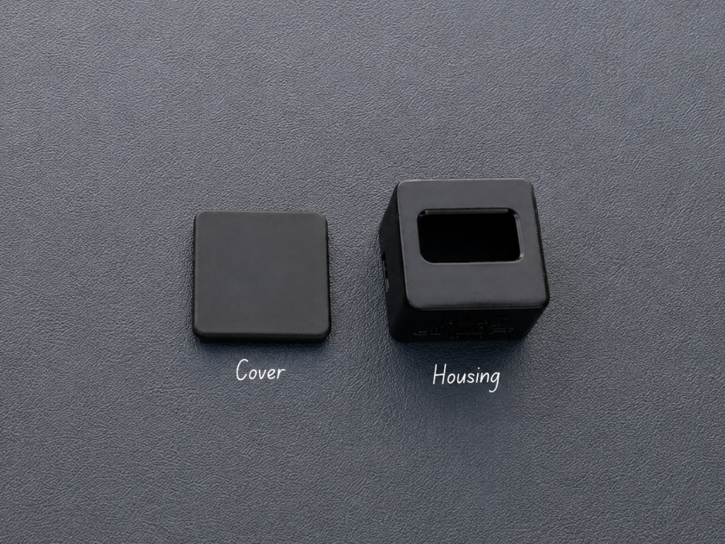
The first step was designing a compact enclosure for Nexus in Autodesk Fusion 360. My goal was to create a clean, minimalist case that would securely hold all the components while looking modern enough to blend into any workspace.
If you'd like to modify the design or add your own personal touch, you can open the Fusion 360 project and edit it however you like. I've also included ready-to-print STL files for anyone who wants to print the enclosure directly.
3D Printing Files:
- 1× Cover.stl
- 1× Housing.stl
I printed the enclosure using black PLA, but you can choose any material or color that matches your style.
Display Assembly
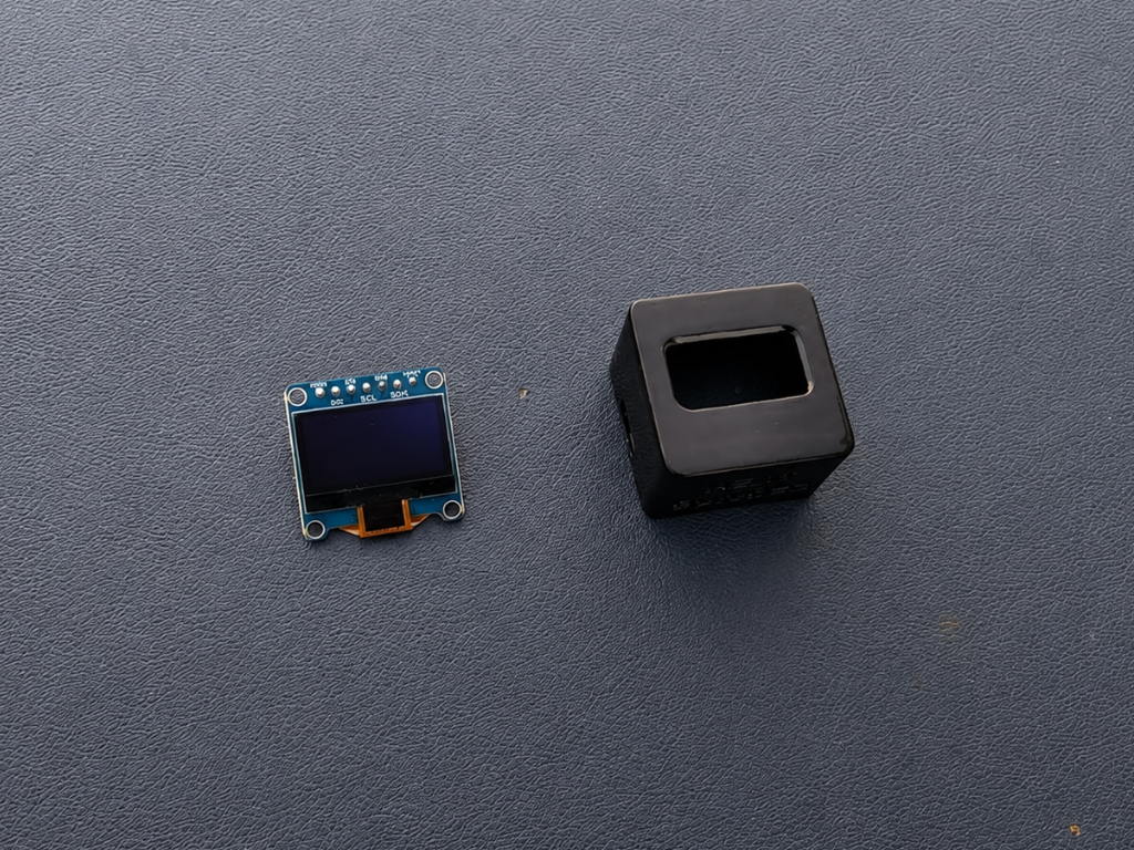
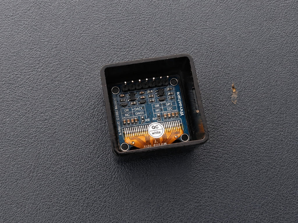
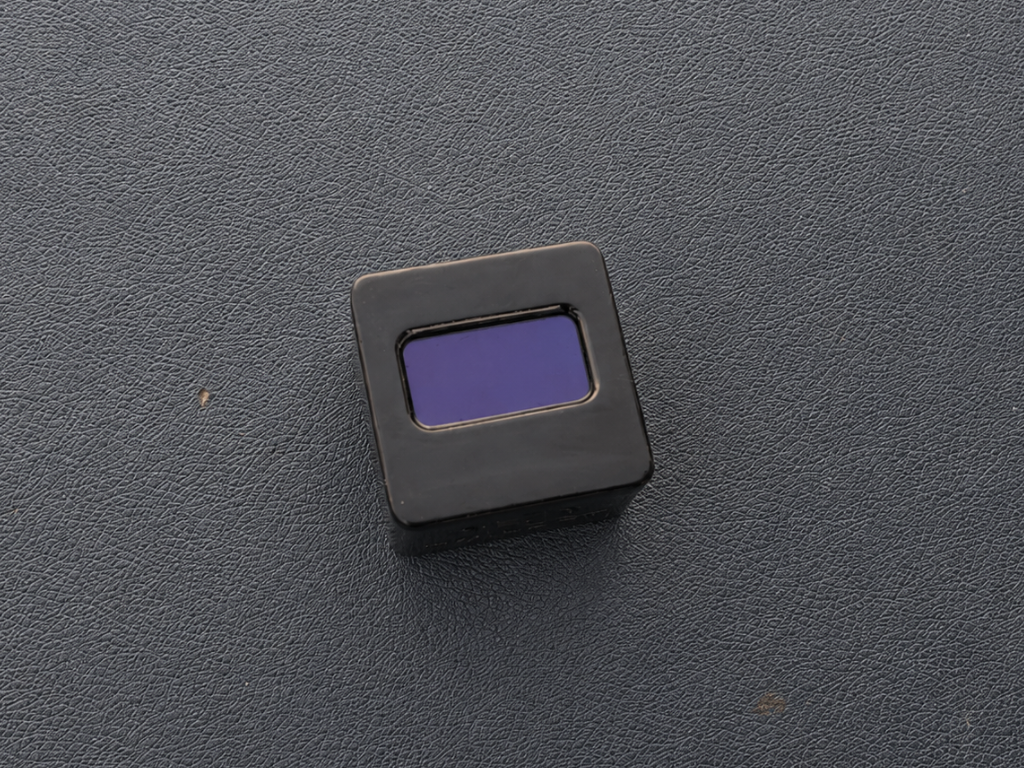
Carefully insert the 0.96-inch OLED display into the front opening of the housing, ensuring that it sits straight and flush with the front surface. Once you're happy with the alignment, secure it using a small amount of super glue around the edges.
Avoid using too much glue, as it may seep onto the display or make disassembly difficult in the future. A few tiny drops are all that's needed to hold the display firmly in place.
Connect the Display
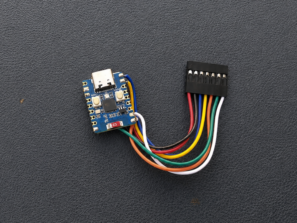
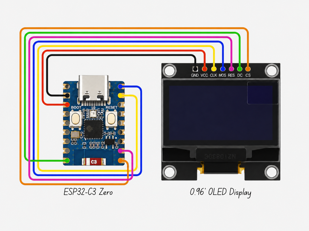
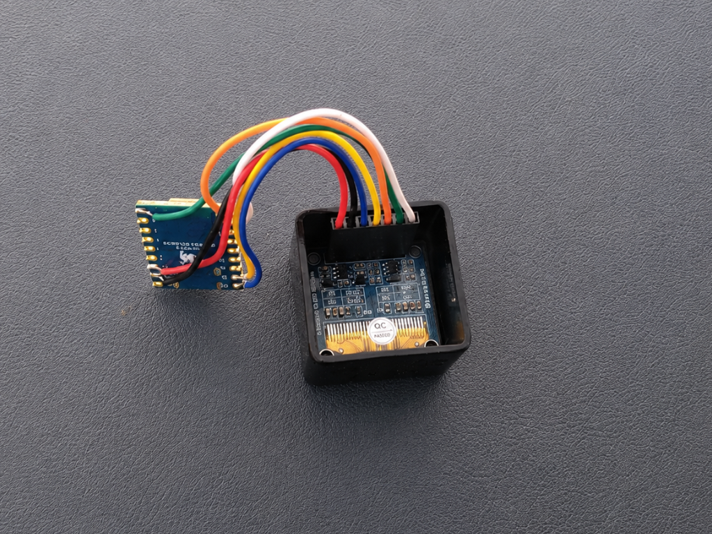
Simply follow the wiring diagram above and connect each pin to its corresponding GPIO on the microcontroller. Take your time and double-check each connection before powering the board to avoid any wiring mistakes.
The pin mapping used for this project is shown below:
- VCC → 3.3V
- GND → GND
- DIN (MOSI) → GPIO 21
- CLK (SCK) → GPIO 20
- CS → GPIO 6
- DC → GPIO 5
- RES → GPIO 7
Once everything is connected, you're ready for the next step.
Assemble the MCU
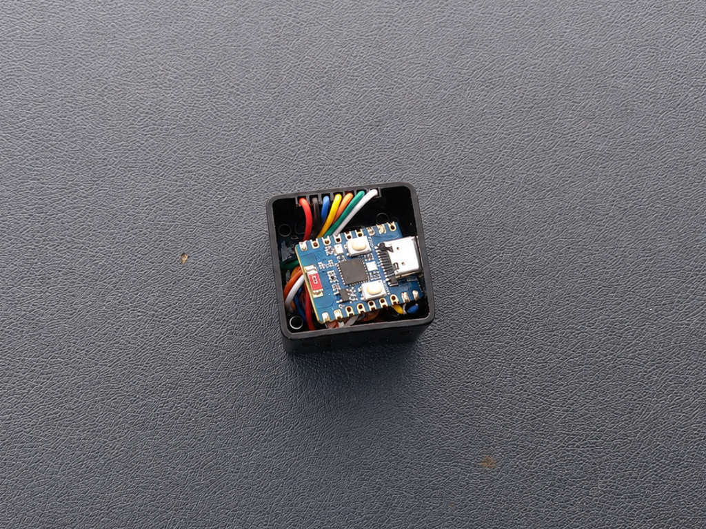
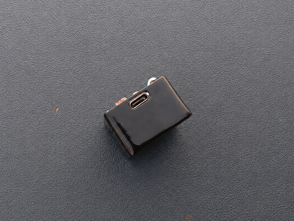
With the display wired up, carefully place the ESP32-C3 Zero inside the enclosure. Arrange the wires neatly so they fit comfortably without putting stress on the solder joints.
Make sure the USB Type-C connector is aligned with the opening in the side of the case. This allows you to easily upload the code or power the clock.
Final Assembly
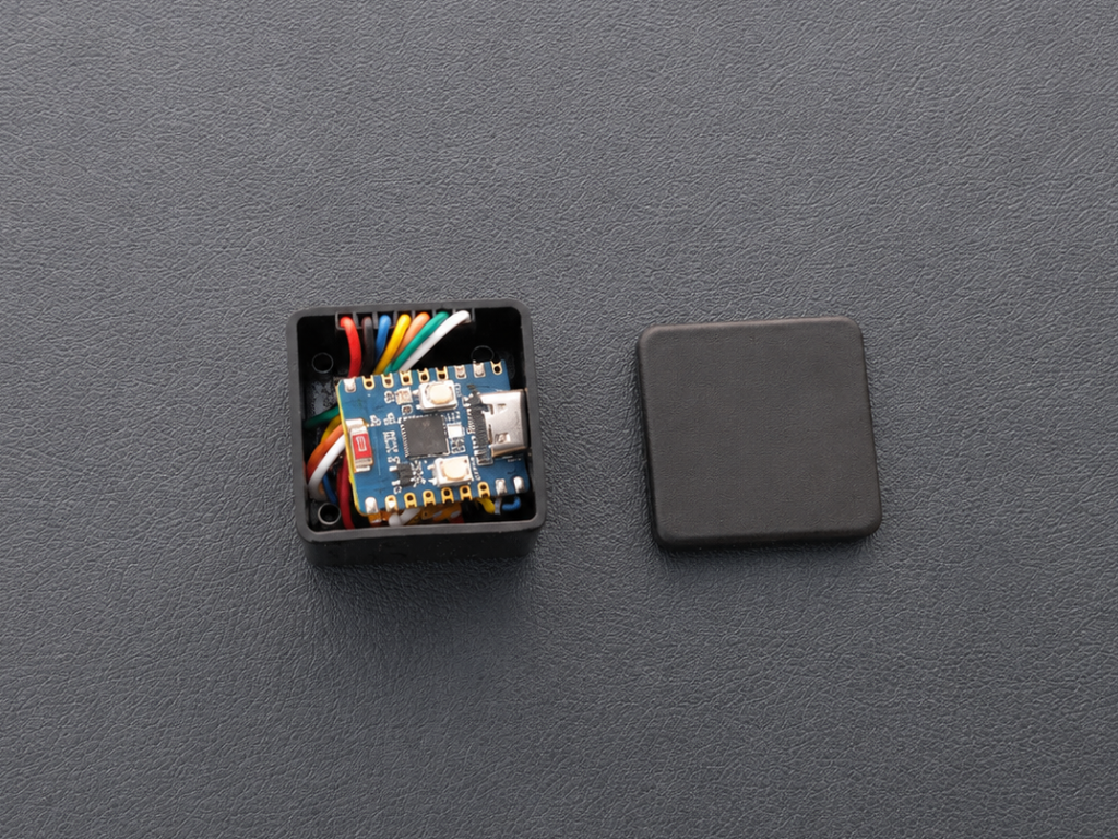
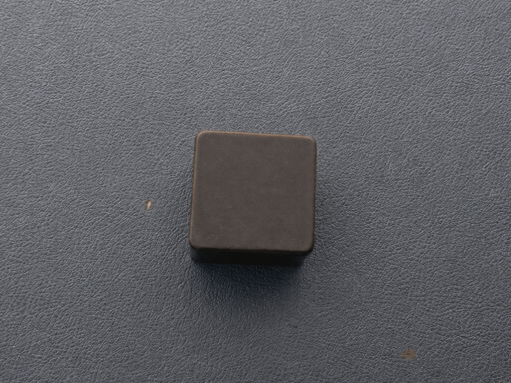
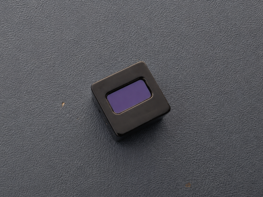
With everything assembled, it's time to close up the enclosure. Carefully place the cover onto the housing, making sure it sits flush on all sides. Once you're happy with the fit, apply a small amount of super glue around the edges to secure it in place.
Set Up the Arduino IDE
Before uploading the code, you'll need to install the Arduino IDE and add support for ESP32 boards.
Install Arduino IDE
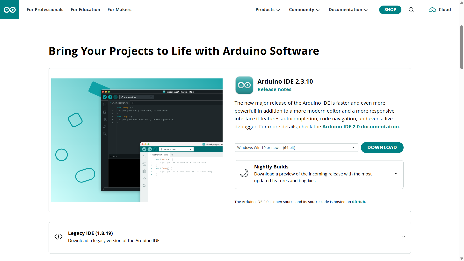
If you don't already have it installed, download and install the latest version of Arduino IDE 2.x from the official Arduino website.
Add ESP32 Board Support
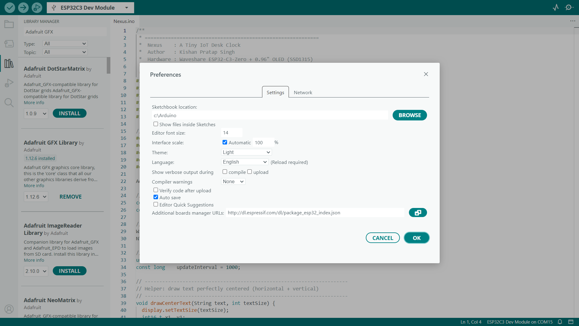
Open Arduino IDE and go to File → Preferences. In the Additional Boards Manager URLs field, paste the following URL:
If you already have other board URLs, simply add this one on a new line & Click OK to save your changes.
Install the ESP32 Boards Package
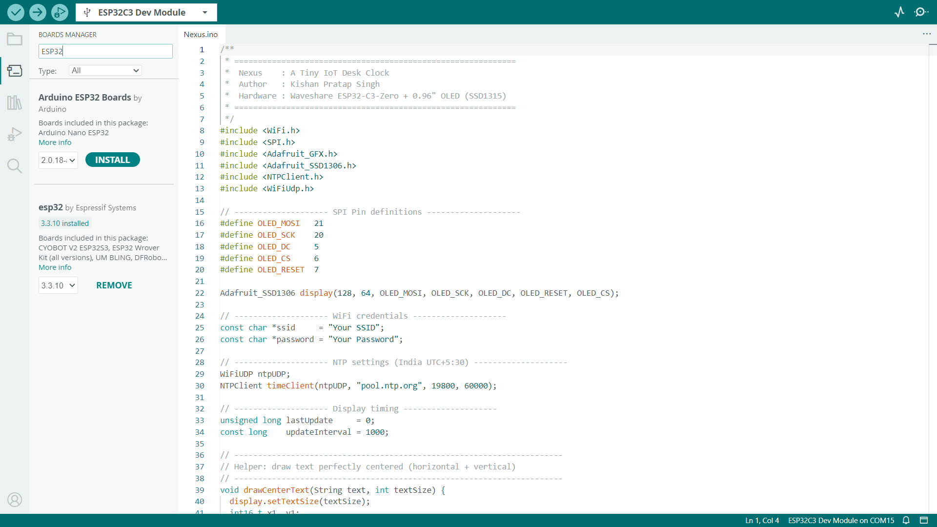
Go to Tools → Board → Boards Manager. Search for ESP32, then install the latest ESP32 by Espressif Systems package.
Configure the Code
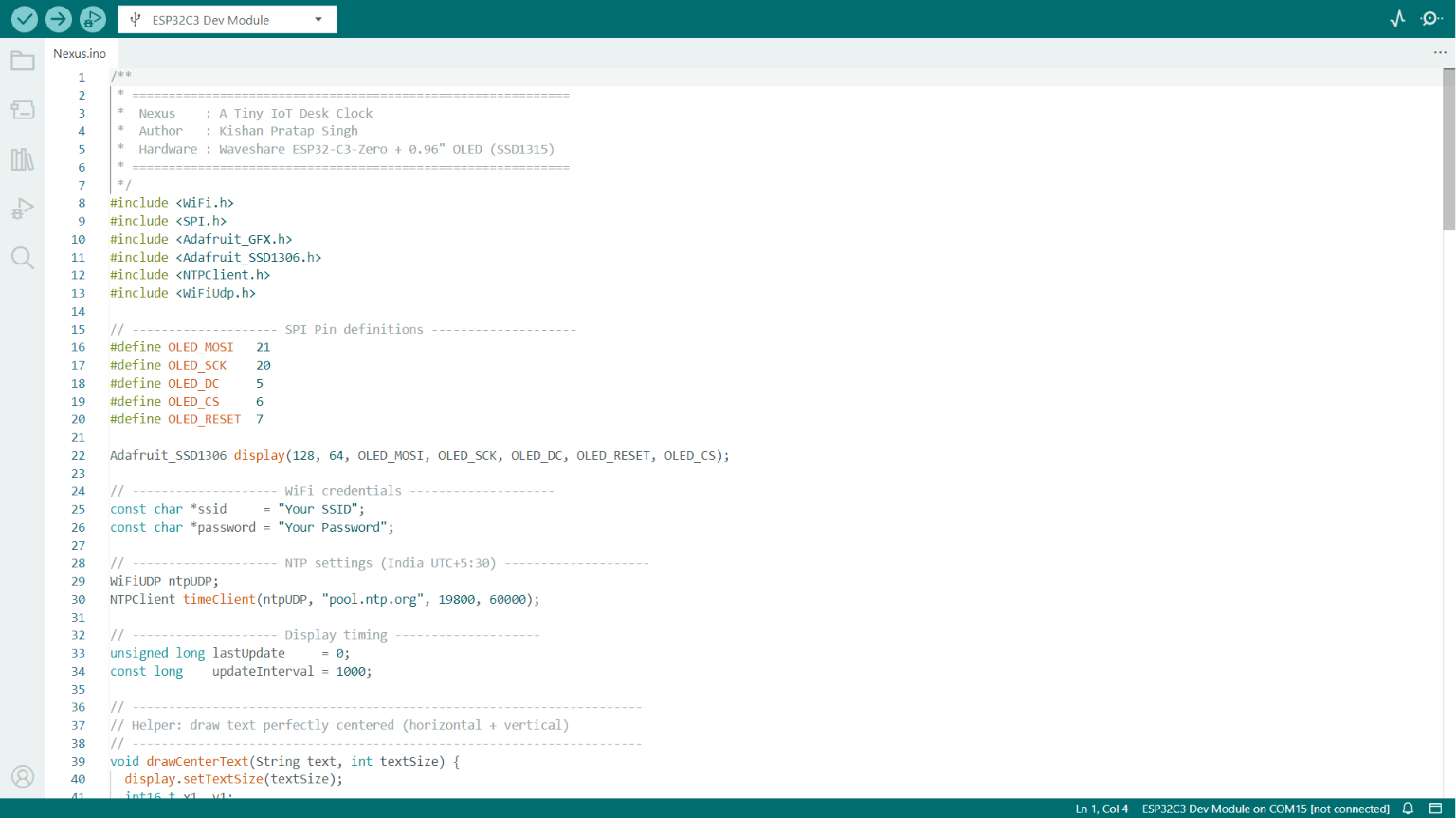
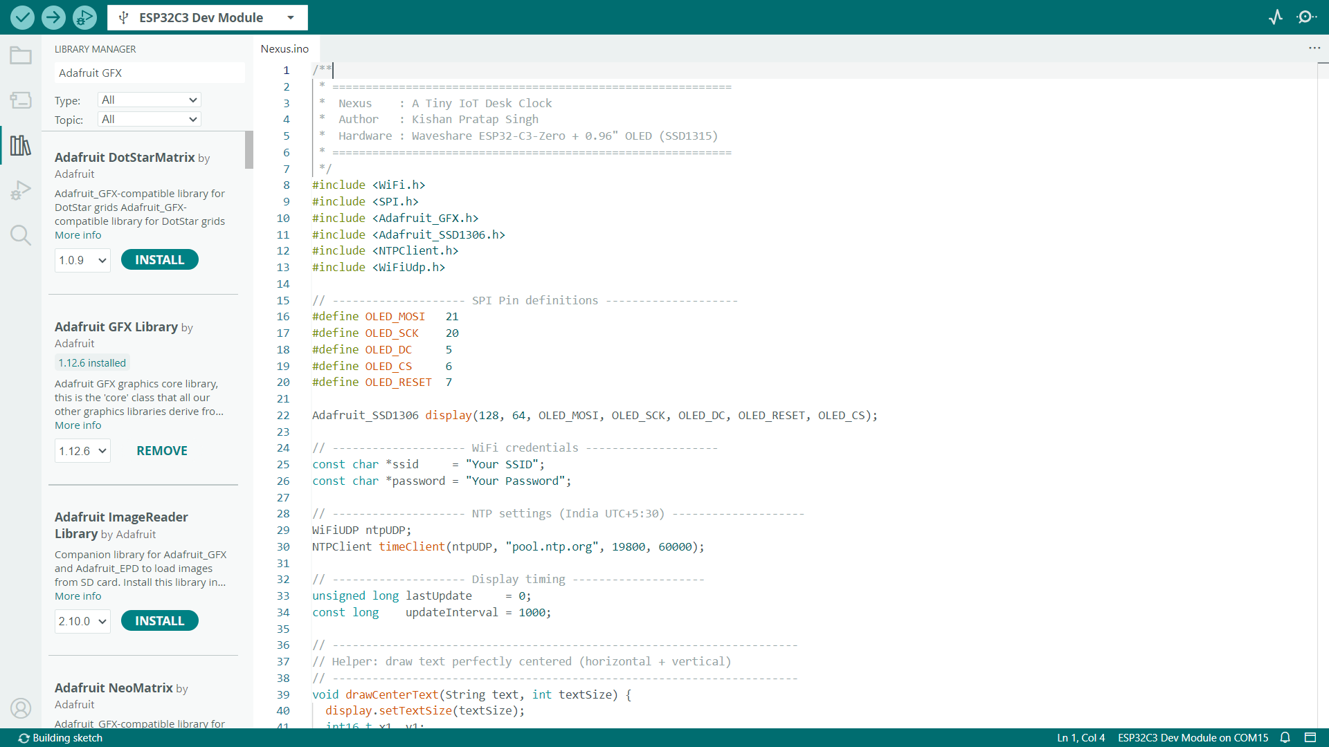
Download the project from the Nexus GitHub repository and extract the ZIP file. Open the Nexus.ino file in the Arduino IDE.
If this is your first time opening the project, make sure the required libraries are installed. Go to Sketch → Include Library → Manage Libraries... and install the following libraries:
- Adafruit GFX Library
- Adafruit SSD1306
- NTPClient
Once the libraries are installed, locate the Wi-Fi credentials in the code:
Replace "Your SSID" and "Your Password" with your Wi-Fi network name and password.
Next, locate the NTP settings:
The value 19800 is the UTC offset in seconds for India (UTC +5:30). If you're in a different country or time zone, replace it with the correct UTC offset for your region.
Upload the Code
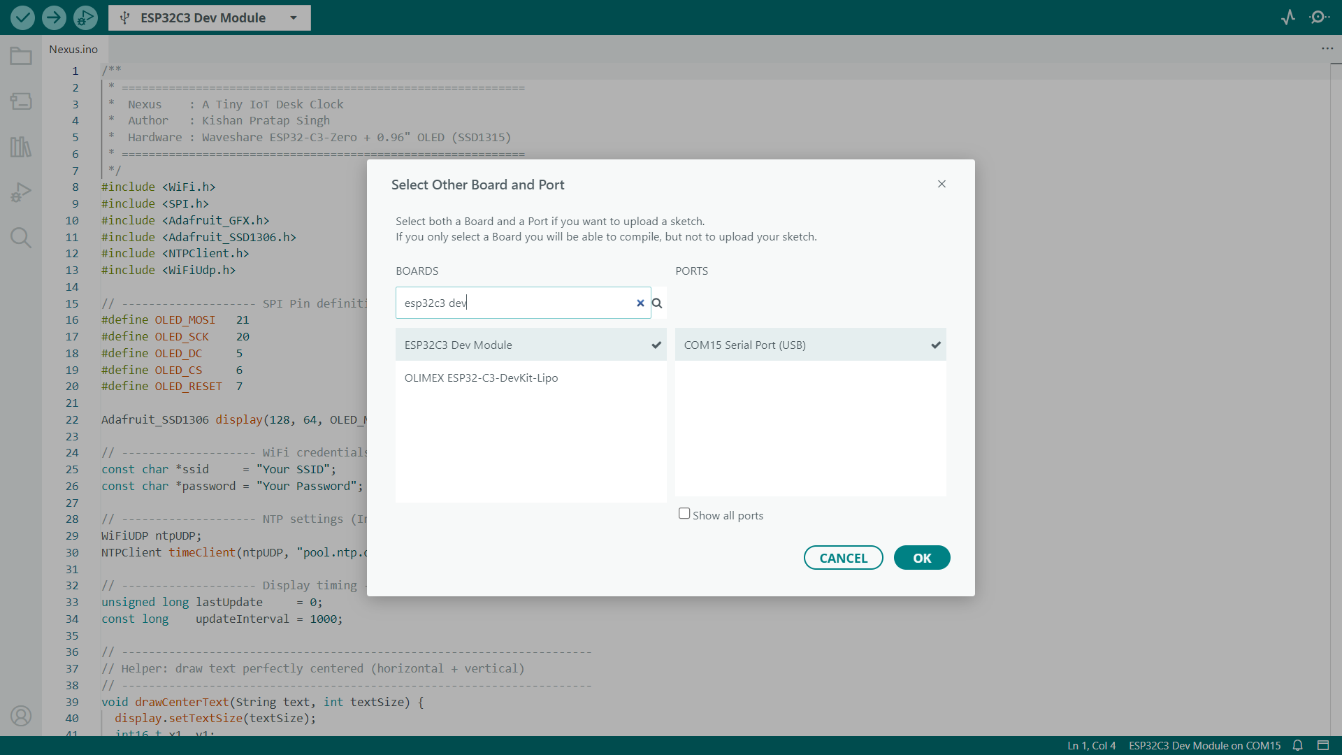
Now Connect the ESP32-C3 Zero to your computer using a USB Type-C cable. In the Arduino IDE, select the correct board and COM port, then configure the following settings from the Tools menu:
- Board → ESP32C3 Dev Module
- USB CDC On Boot → Enabled
- CPU Frequency → 160 MHz
- Core Debug Level → None
- Erase All Flash Before Sketch Upload → Disabled
- Flash Frequency → 80 MHz
- Flash Mode → QIO (use DIO if the upload fails)
- Flash Size → 4MB
- Partition Scheme → Default 4MB with SPIFFS (1.2MB APP / 1.5MB SPIFFS)
- Upload Speed → 921600
- JTAG Adapter → Disabled
Once everything is configured, click the Upload button and wait for the sketch to finish uploading.
Testing
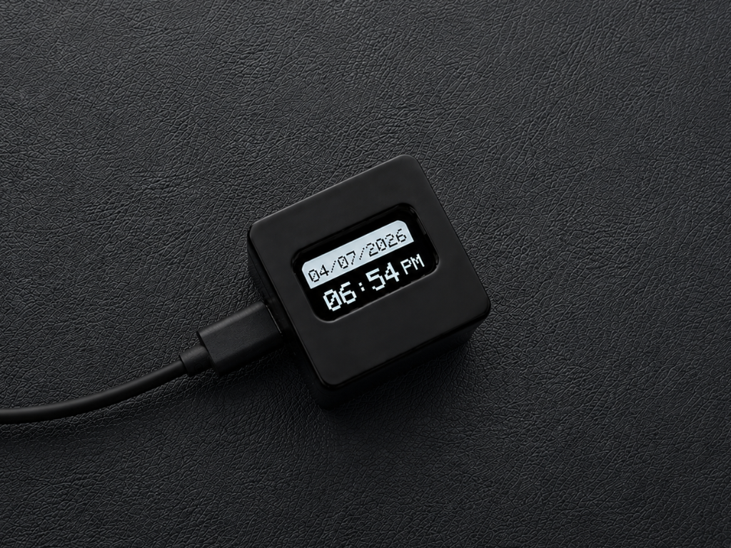
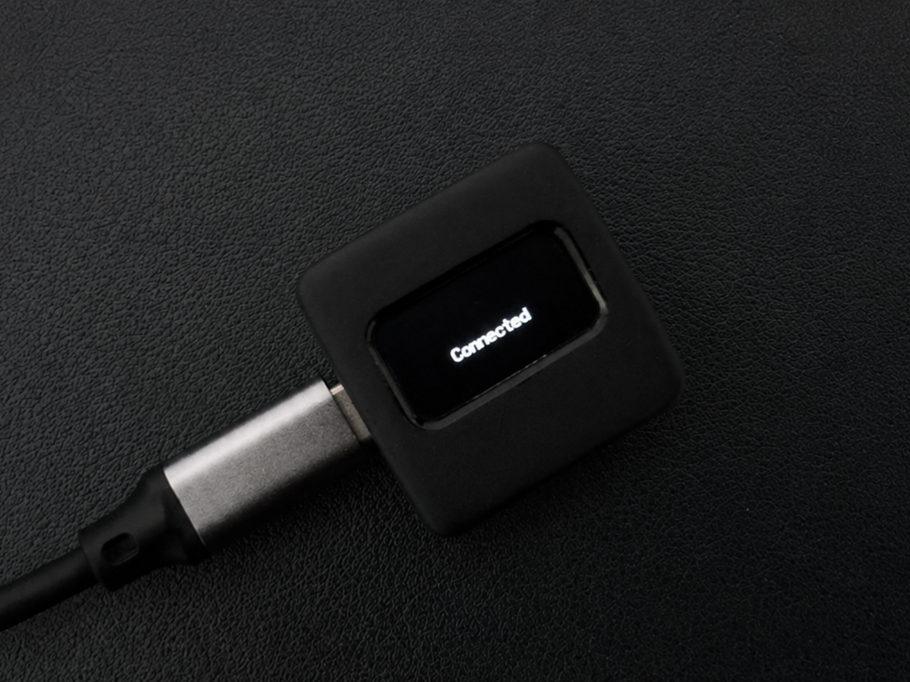
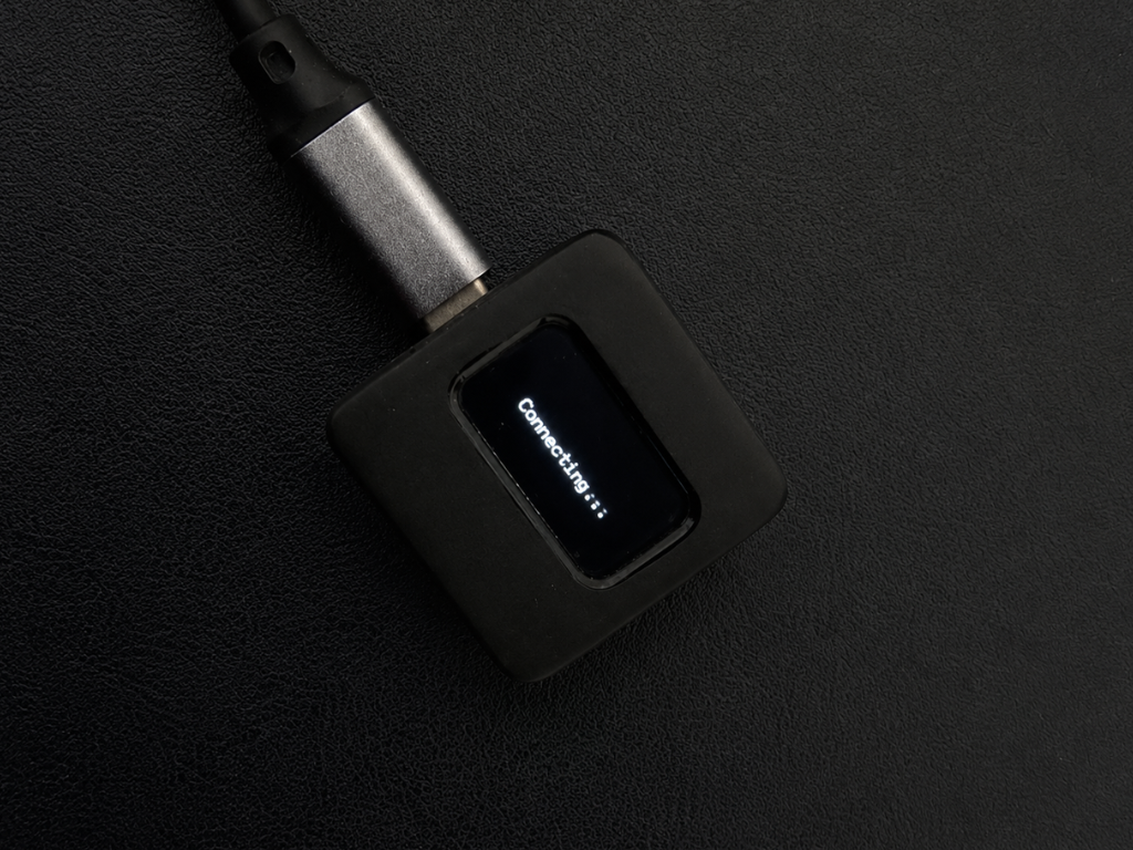
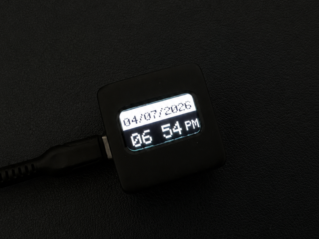
Now it's time to test your Nexus. Once the board powers up and connects to your Wi-Fi network, it will automatically synchronize with an NTP (Network Time Protocol) server to fetch the current date and time.
After a few seconds, the OLED display will show the current date at the top in DD/MM/YYYY format, while the current time is displayed below in 12-hour (HH:MM) format along with the AM/PM indicator.
Final Thoughts
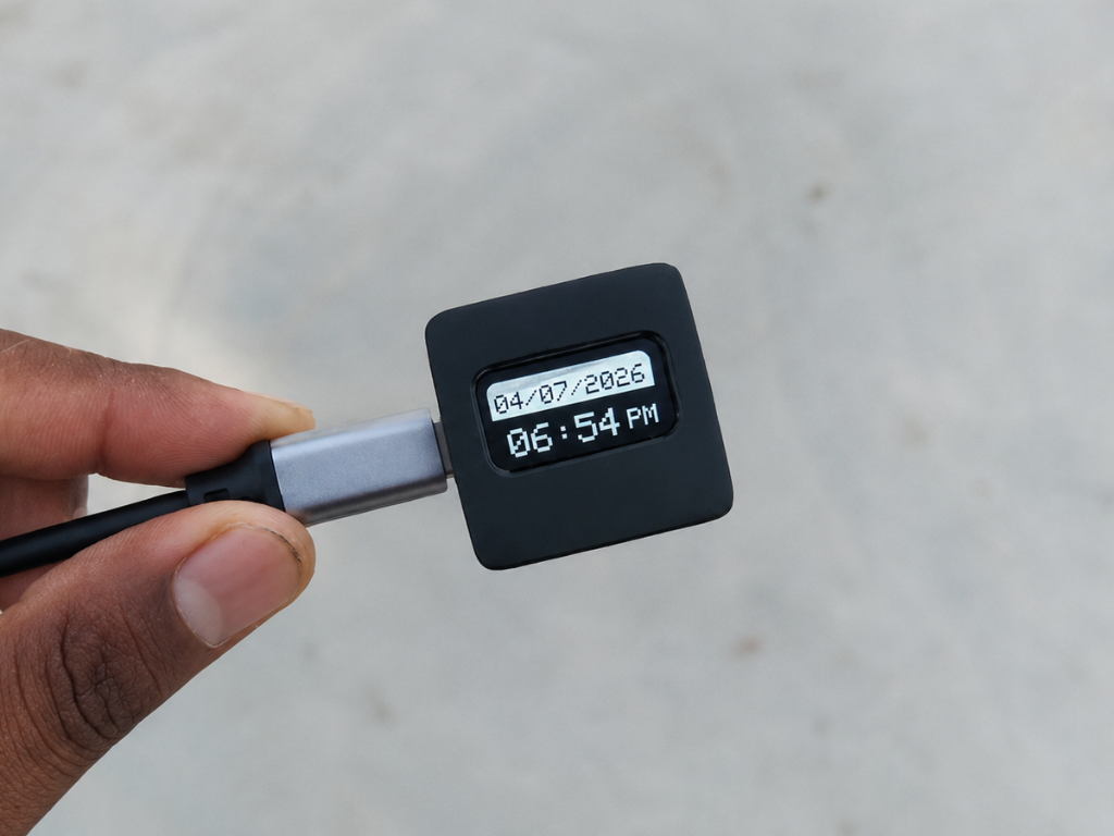
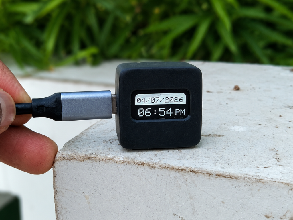
And that's it—your Nexus Wi-Fi desk clock is ready!
Although it's a simple project, it has become one of my favorite additions to my workspace. Instead of reaching for my phone every time I need to check the time, I can simply glance at Nexus and stay focused on what I'm doing. Sometimes, it's the small changes that make the biggest difference.
I hope you enjoyed building this project as much as I enjoyed designing and sharing it. If you decide to build your own version, I'd love to see it! Feel free to share a photo in the "I Made It!" section or leave a comment below if you have any questions or ideas for improvements.
Happy making! 🚀