Nintendo Power Pad to USB Adapter
by arpruss in Living > Toys & Games
225 Views, 1 Favorites, 0 Comments
Nintendo Power Pad to USB Adapter
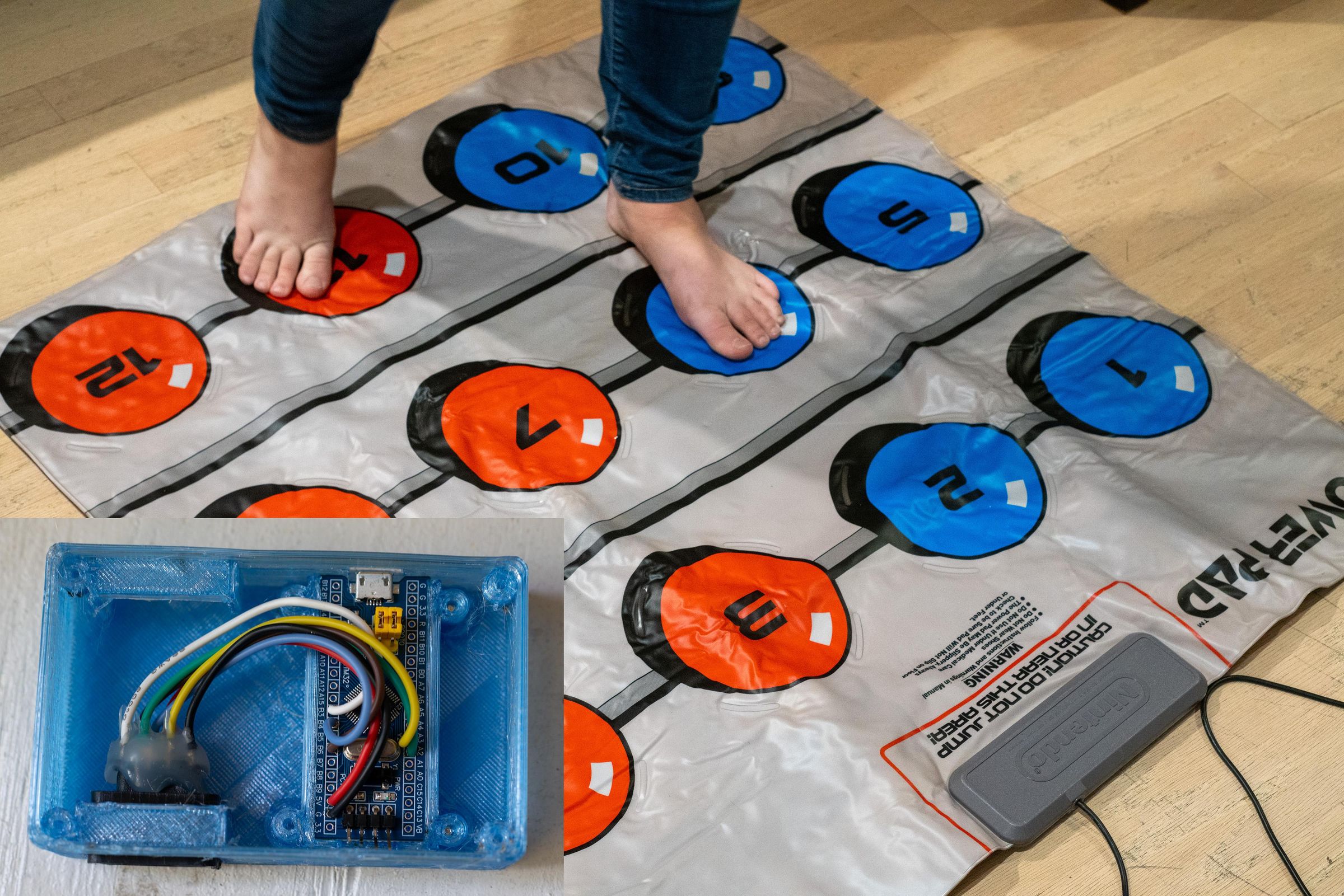
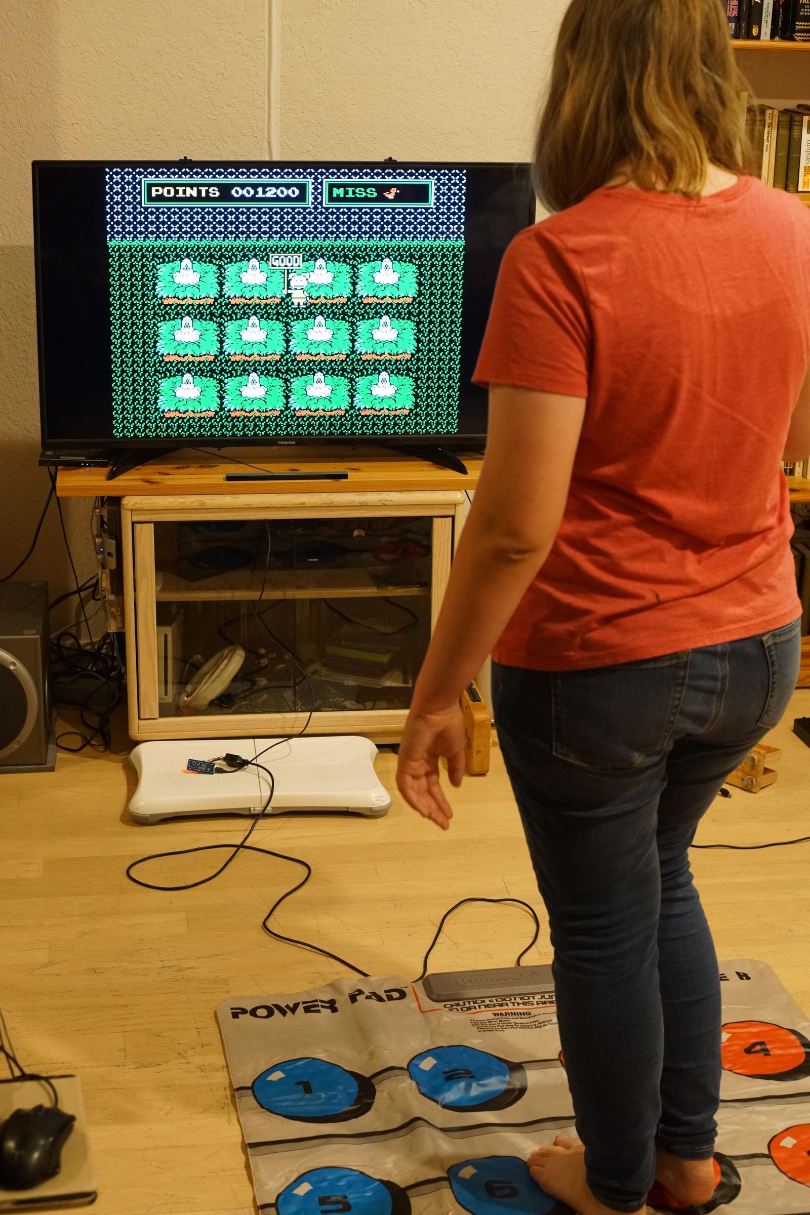
The Nintendo Power Pad was a mat-based controller for the NES, well before Dance Dance Revolution. The most famous game for it was the bundled World Class Track Meet, but the one I like the most is Eggsplode. For a while now I've been playing NES Power Pad games in emulation using two DDR pads joined together, but I just acquired an original Power Pad in excellent condition and wanted to try the games with it (the DDR pads make for a larger play surface, so the game experience is not the same). To that end, I needed to make a USB adapter so I can use the Power Pad with FCEUMM (also works with Nestopia). The adapter makes the Power Pad emulate sixteen keys of a keyboard: qwer/asdf/zxcv.
I used a cheap Blue Pill board with Roger's libmaple core and my USBHID library.
Supplies
- Blue Pill STM32F103C8T6 board
- USB to TTL serial adapter (or an Arduino)
- NES controller port socket (you can either order a standalone socket, or rip one out of a NES controller extension cord)
Load Firmware
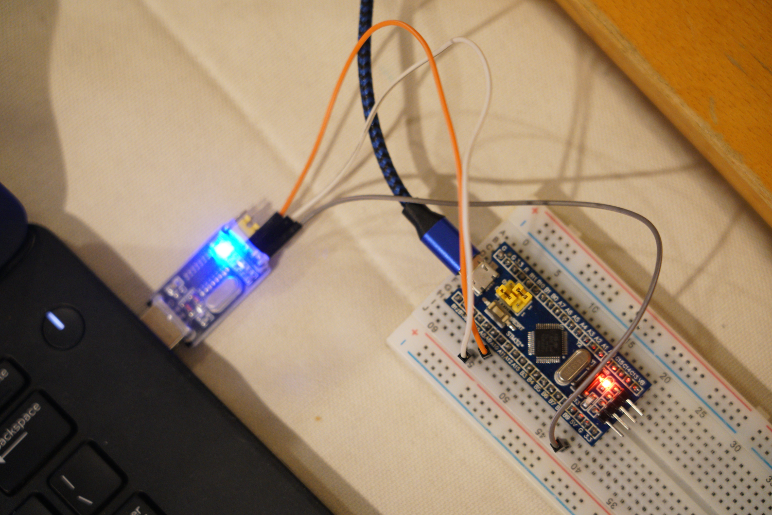
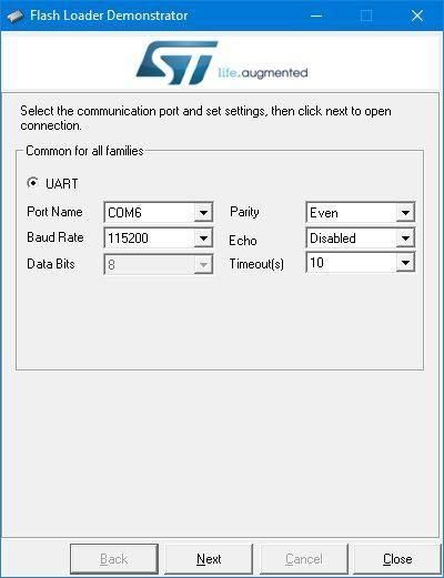
Upload the firmware to the blue pill as follows. First, get the powerpad.bin file from my github repo (you can also build the project yourself using source code and a bootloader and my Arduino setup instructions for an older version of this project) On Windows, I've used the Flash Loader Demonstrator. Make the following connections:
- Blue pill A9 to serial adapter RX
- Blue pill A10 to serial bridge TX
- Blue pill ground to serial bridge ground
(Actually, I am usually lazy and plug both the blue pill and the serial adapter to the the same computer's USB, and the grounds are close enough that I don't bother with the direct ground connection.)
If you don't have a USB-TTL serial adapter, you can use an ordinary Arduino.
On the blue pill, there are two sets of jumpers, each on a trio of pins. Make the first jumper (B0) join the center pin with the right pin (center to B0+ or center to 1, depending on labeling). Make the second jumper (B1) join the center pin with the left pin (center to B1- or center to 0, depending on labeling).
Power up the blue pill via its USB port (if you connect it to the computer, the computer will likely complain about an unrecognized USB device; ignore that). Start the Flash Loader Demonstrator. Choose the COM port for your serial adapter (the Windows Device Manager can help there). Choose "Remove protection" if available. Choose a 64kb rather than 128kb flash version. And download the firmware binary file into the device. Unpower everything and then move the first jumper left+center.
Plug into PC and make sure that Windows Device Manager shows a new HID device (keyboard).
Make Connections
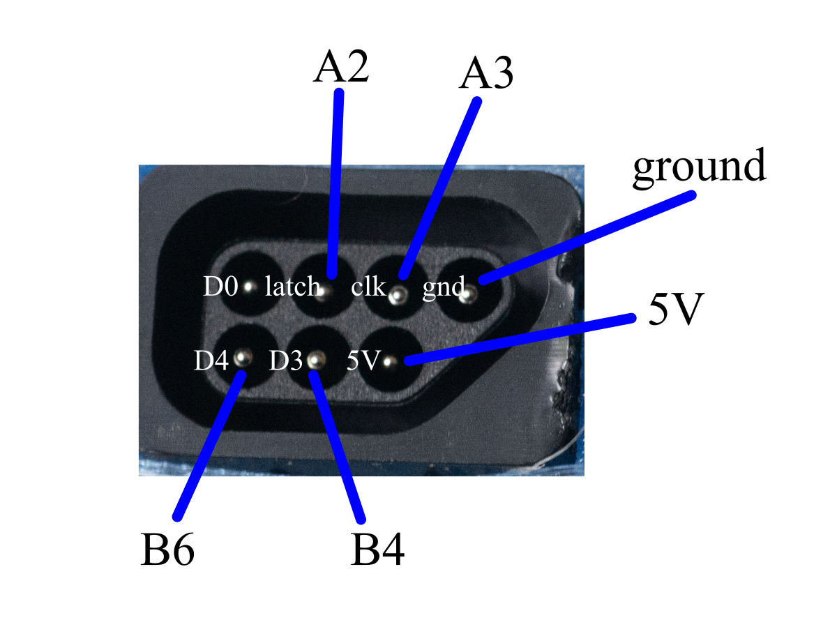
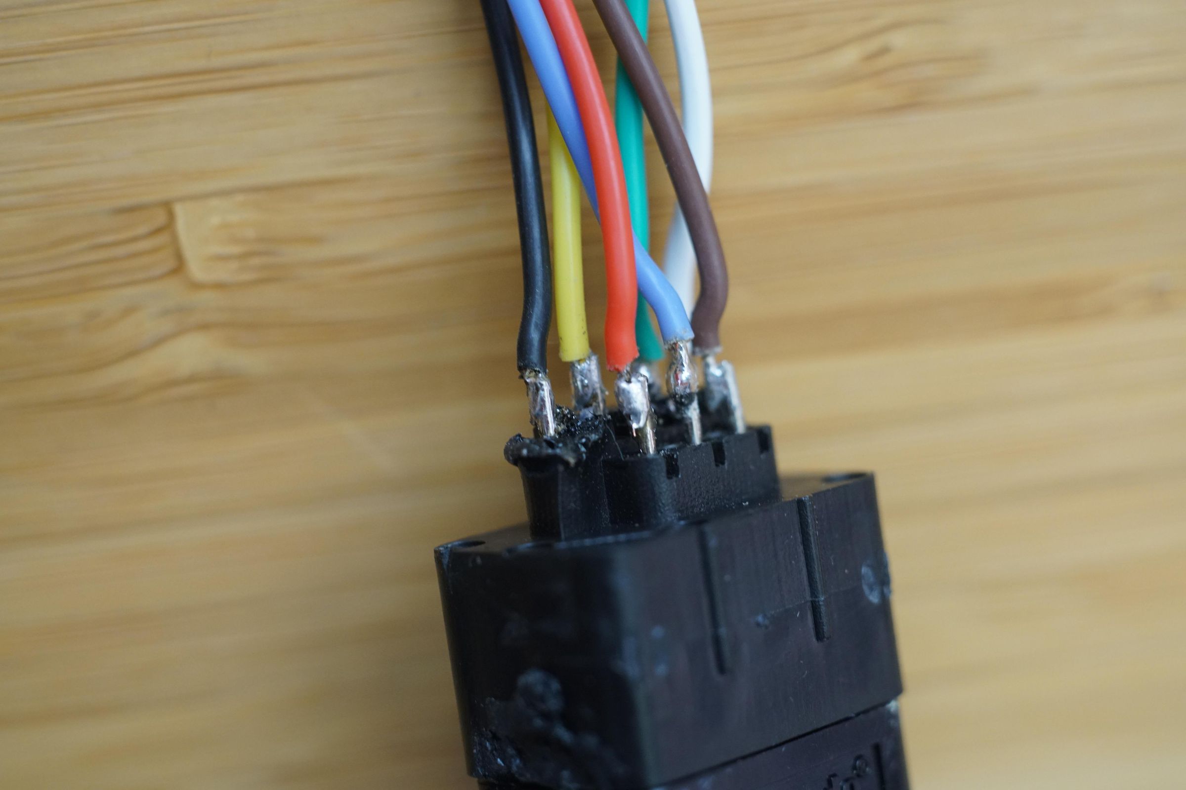
I made the mistake of ordering what Amazon labeled as "7 pin" extension cords for NES controllers, hoping I could just cut them in half, use the female and solder the cables to the blue pill. Unfortunately, while it does have 7 pins in the socket, it only has five cables, leaving the D3 and D4 pins that the Power Pad uses unconnected. I ended up ripping (with some help from a rotary tool) the female connector out of its housing, and soldering cables to the pins directly.
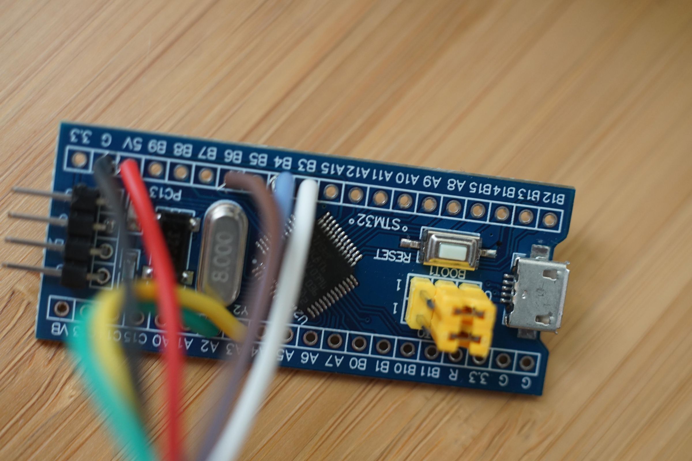
Make the following connections following the diagram above.
- NES GND - blue pill GND
- NES 5V - blue pill 5V
- NES latch - blue pill A2
- NES clk - blue pill A3
- NES D4 - blue pill B6
- NES D3 - blue pill B4
For future use, I suggest also connecting NES D0 with blue pill B3. This way if I ever extend the firmware to work with a standard NES controller, you can upgrade to that functionality. (The D0 pin is used for the standard controller.)
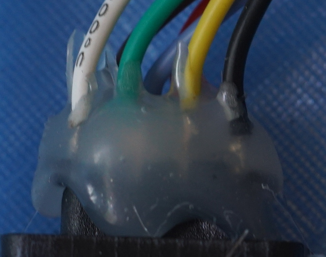
Hints: When I took the female end of the extension cord apart, the pins were held in place with a hot glue. After removing that, one of the pins was completely loose. I found it easiest to solder wires to the pins by just pulling out each pin, soldering to the end, and putting it back in, trying to keep it centered. The loose pin was an issue. After soldering and testing, I ended up plugging in the Power Pad's plug to make the pins be centered, and then generously put hot glue on the soldered ends.
Test
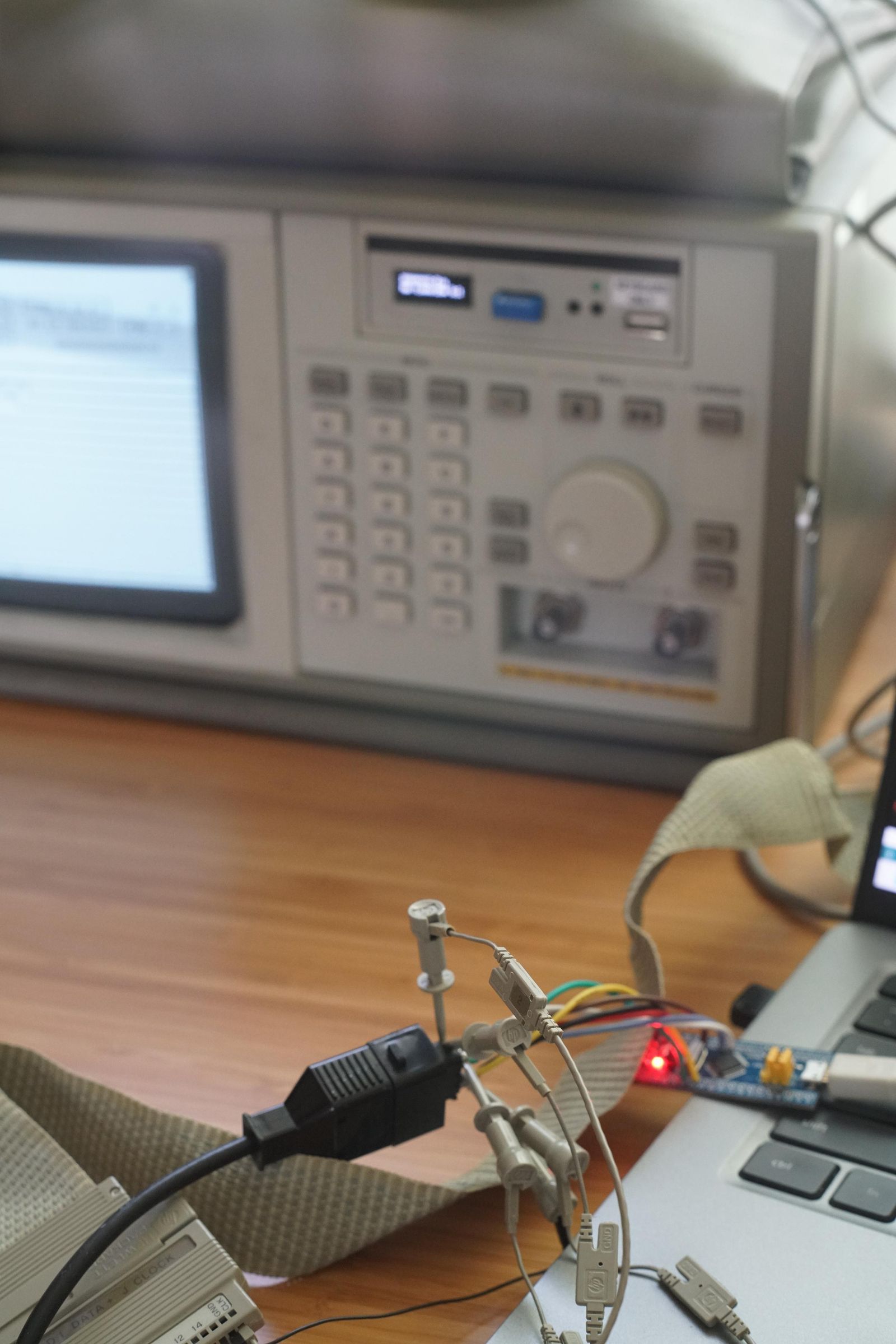
Verify the connections with a multimeter (or for overkill with a logic analyzer!).
Plug the Power Pad into the socket.
Connect with a USB cord to PC.
Check that the power pad side B is generating qwer/asdf/zxcv.
Flip the pad to side A, and activate Scroll Lock on your computer. This will tell the adapter to reverse the mappings for the reversed pad (fceumm expects to see qwer/asdf/zxcv for games that use side B and games that use side A). If your computer keyboard doesn't have a Scroll Lock key, you may need to figure out how to do this. On my Dell laptop, fn-s does it. On my Raspberry PI, I can activate Scroll Lock with the command
and then deactivate it with
(I have one game that uses side A, Athletic World, and I have a script that does the above when I launch it.)
Play!
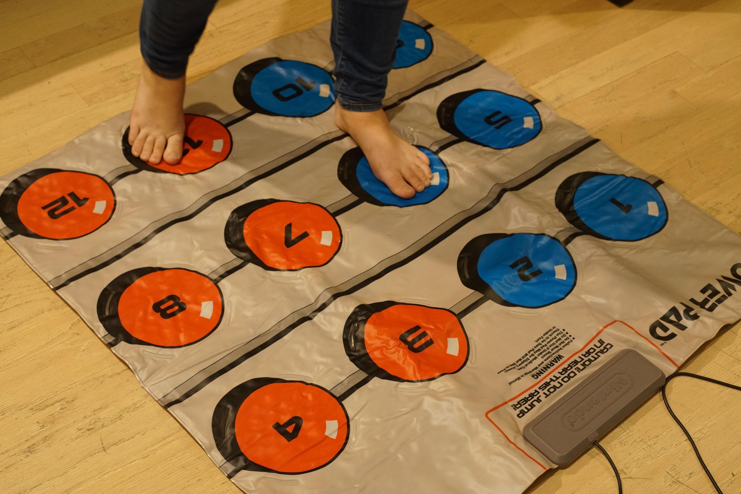
Use a version of fceumm that's not too old. (I added Power Pad keyboard support to fceumm at least three years ago.) Enjoy!
You can also use the Power Pad for DDR-like games if you remap the game appropriately.
Case (optional)
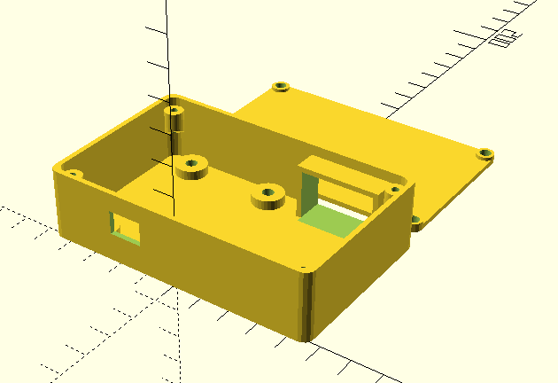
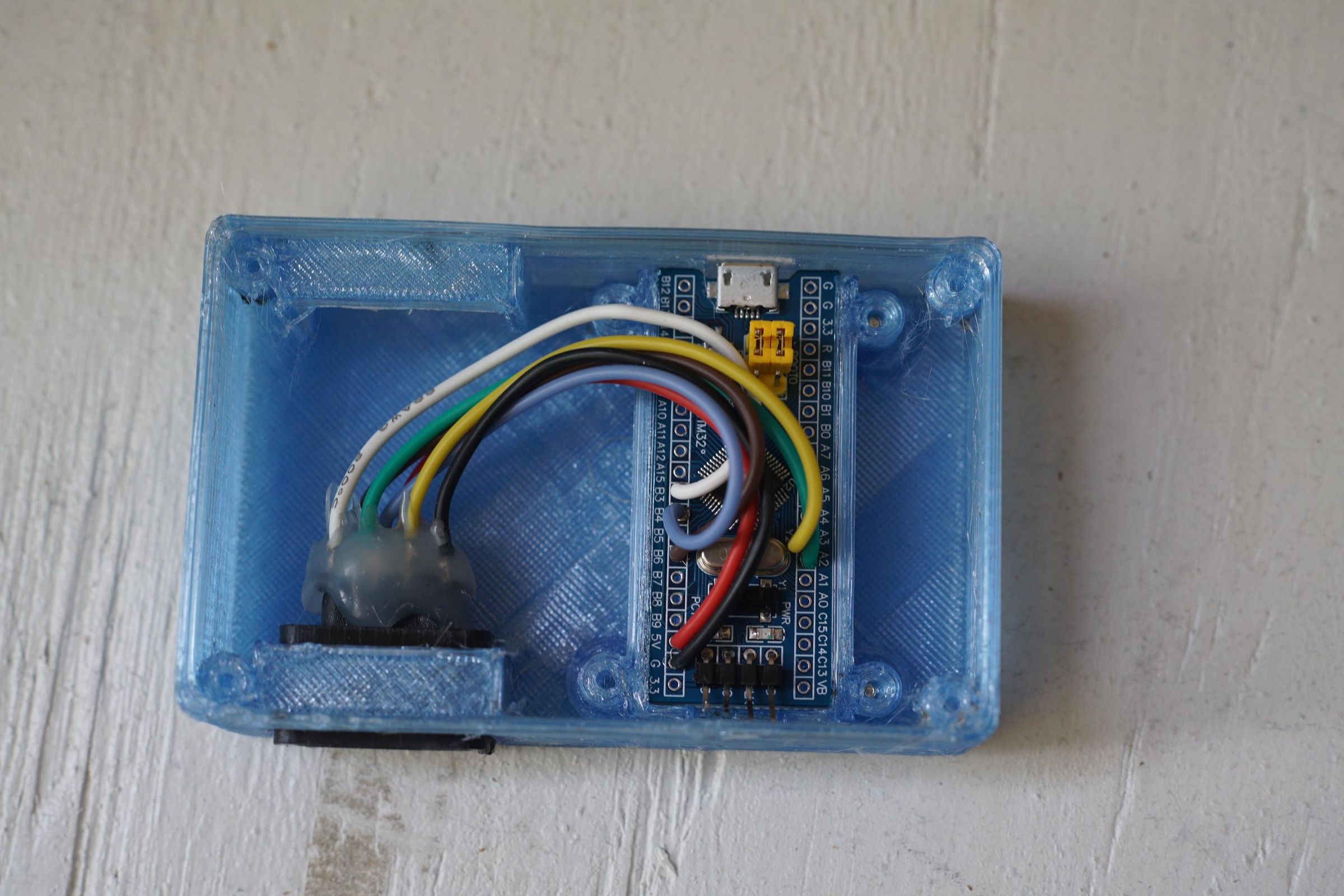
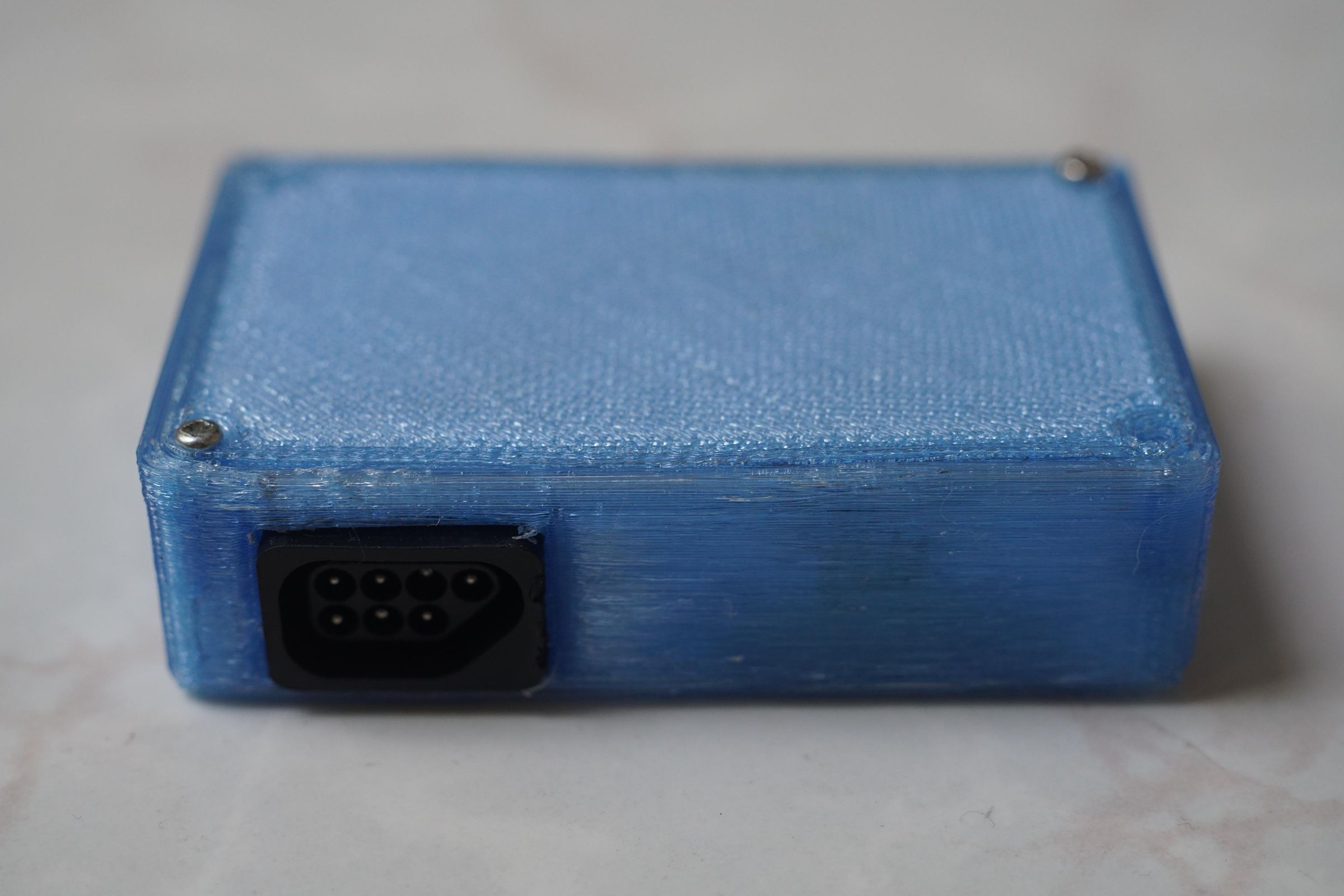
I made a simple 3D printed case (files here). You may need to tweak the OpenSCAD file if your NES sockets are differently sized from mine. (I ended up trimming some things on the socket sides to fit.)
Technical Notes
The blue pill is a 3.3V board, while NES controllers are designed for 5V. But I had no problem with the Power Pad as long as I powered it via 5V, and made sure that I connected the Power Pad's output pins (D0/D3/D4) to 5V-tolerance pins on the blue pill.
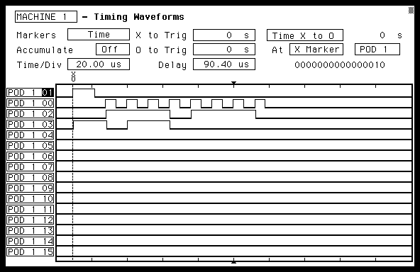
You read from an NES controller by sending a pulse on the latch pin. Shortly, the first data bits come through on the controller lines (D3 and D4 for the Power Pad), with HIGH=0 and LOW=1. You then send pulses on the clock line to get the remaining seven data bits on the controller. The NES actually apparently sends eight pulses on the clock line from the information, with the last pulse not providing any data.
My reference material was this and this. I used the same timings that the NES apparently does (basically 12 microseconds per bit), but experiments showed a wide range of flexibility on the timings--I could read a lot faster if I wanted to.
In the image are logic analyzer traces (screenshot from my HP1653b) for my adapter while buttons 2, 3 and 6 are pressed down. The lines from top to bottom are latch, clock, D3 and D4. Note that the last four bits on the D4 line are always low (i.e., 1) when using the Power Pad.