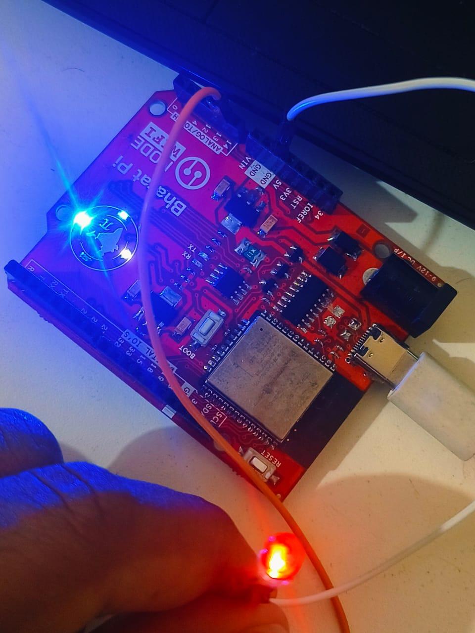
ON AND OFF ALED USING BHARAT PI BOARD AND TRANSMITING IT TO CLOUND TO SWITCH ON AND OFF THE LED
40 Views, 0 Favorites, 0 Comments
ON AND OFF ALED USING BHARAT PI BOARD AND TRANSMITING IT TO CLOUND TO SWITCH ON AND OFF THE LED


Blynk Cloud Integration:
- The code uses Blynk to establish a connection between the ESP32 and the Blynk Cloud.
- The virtual pin V1 is linked to a button widget in the Blynk app to control the LED state.
WiFi Connection:
- The ESP32 connects to the internet using your WiFi credentials (ssid and pass).
- Upon successful connection to WiFi and Blynk Cloud, the device is ready to receive commands.
LED Control:
- An LED is connected to GPIO 13 (LED_PIN) of the ESP32.
- When the user toggles the button in the Blynk app, the state of the LED changes accordingly.
- The code ensures that the LED is turned off initially (digitalWrite(LED_PIN, LOW)).
Button Interaction:
- The BLYNK_WRITE(V1) function listens for button presses from the Blynk app.
- The virtual pin V1 sends the button state (0 or 1) to the ESP32, and the LED is controlled based on this input.
Supplies
.png)
.png)
Hardware Requirements:
- ESP32 development board.
- LED.
- Resistor
Connections:
- LED:
- Long leg (Anode) of the LED → Connect to GPIO 13 of the ESP32 (defined as LED_PIN in the code).
- Short leg (Cathode) of the LED → Connect to one leg of the resistor.
- The other leg of the resistor → Connect to GND on the ESP32.
- WiFi:
- Ensure your ESP32 is powered and connected to the same WiFi network as configured in the code (ssid and pass).
Connection Table:
LED PinConnects To
Long leg (Anode)
GPIO 13 (LED_PIN)
Short leg (Cathode)
Resistor → GND
Notes:
- Optional Resistor: If you skip the resistor, the LED might draw too much current, potentially damaging the LED or the ESP32 pin. Use a 220Ω or 330Ω resistor to limit current.
- GPIO Pin Selection: If GPIO 13 is already in use or inaccessible, change the #define LED_PIN value in the code to an available GPIO pin, and connect the LED accordingly.
- Power Source: Power the ESP32 via USB or an external 5V power supply.
Testing the Connection:
- Verify the LED turns ON when the button in the Blynk app is pressed.
- If the LED doesn’t respond:
- Check the GPIO pin mapping.
- Confirm the Blynk app is linked correctly to Virtual Pin V1.
- Check for loose connections or incorrect polarity of the LED.
CODING
#define BLYNK_TEMPLATE_ID "TMPL34yhUAgOe"
#define BLYNK_TEMPLATE_NAME "LED1"
#define BLYNK_AUTH_TOKEN "lQgz0RXOeV8pIQeYC6vvC9SiRhyWLMfL"
#include <WiFi.h>
#include <BlynkSimpleEsp32.h> // Use the Blynk library for ESP32 or Bharat Pi
const char* ssid = "Yogesh"; // Your Wi-Fi SSID
const char* pass = "Yogi5244"; // Your Wi-Fi Password
// Define the GPIO pin where the LED is connected
#define LED_PIN 13
// Define the switch state for controlling the LED
bool ledState = false;
void setup() {
// Initialize Serial Monitor for debugging
Serial.begin(115200);
// Connect to WiFi
Serial.print("Connecting to WiFi...");
WiFi.begin(ssid, pass);
while (WiFi.status() != WL_CONNECTED) {
delay(1000);
Serial.print(".");
}
Serial.println("\nConnected to WiFi");
// Initialize the Blynk connection
Serial.print("Connecting to Blynk...");
Blynk.begin(BLYNK_AUTH_TOKEN, ssid, pass);
// Set the LED_PIN as OUTPUT
pinMode(LED_PIN, OUTPUT);
digitalWrite(LED_PIN, LOW); // Initialize the LED to be OFF
Serial.println("Blynk Connected.");
}
// Blynk button widget will control the LED state
BLYNK_WRITE(V1) {
ledState = param.asInt(); // Get the state of the virtual switch (0 or 1)
Serial.print("Button State: ");
Serial.println(ledState); // Debugging: Print the state of the button
if (ledState == 1) {
digitalWrite(LED_PIN, HIGH); // Turn the LED ON
Serial.println("LED is ON");
} else {
digitalWrite(LED_PIN, LOW); // Turn the LED OFF
Serial.println("LED is OFF");
}
}
void loop() {
Blynk.run(); // Maintain the Blynk connection
}