OP-Z Replacement Battery | Supercapacitors
by Jimothea in Circuits > Audio
26 Views, 0 Favorites, 0 Comments
OP-Z Replacement Battery | Supercapacitors
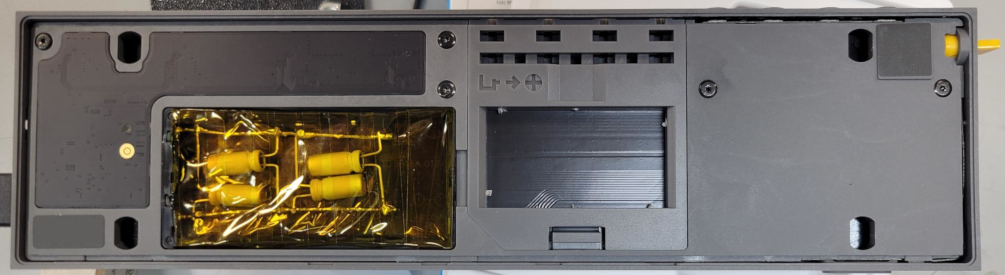
For those of you who, like me, enjoy working and playing with OP-Z but have suffered from the early death of the battery, this is for you. These instructions assume that you have a basic working knowledge of soldering and electronics but is rather simple. If you are unsure, please read through the whole list of instructions first and practice portions that you are uncomfortable with and use proper PPE. Burns, cuts, toxic fumes and the destruction of your unit are all possibilities of mistakes. That said, with some precaution and preparation, this is something anyone can do.
About the supercapacitor swap: This will only get you about 5 minutes of off charging use. I chose to move in this direction to modify the OP-Z to always require power input (from an outlet or power bank; this can still go mobile) but I will never have to worry about the battery degrading again. My typical workflow makes this requirement trivial and I wanted to push for the greater long-term reliability of just using capacitors to mimic the power draw buffer that a battery provides. The OP-Z seems to need this buffer as it will auto-shutdown if it sees the battery voltage is too low after a certain amount of time.
For the lawyers:
> **Warning:** This procedure involves modifying the unit's power system and working with conductive materials, soldering equipment, and an energy storage device. Disconnect the unit from all power sources before beginning. Take appropriate ESD and electrical safety precautions throughout the procedure.
Supplies
* Non-conductive prying tool (a plastic spudger or an old credit card works well)
* Wire cutters / flush cutters (preferably a large set and and a small set)
* Soldering equipment
* Electrical tape
* Kapton tape (polyimide film)
* Two stiff conductive posts (uncoated paper clips work well)
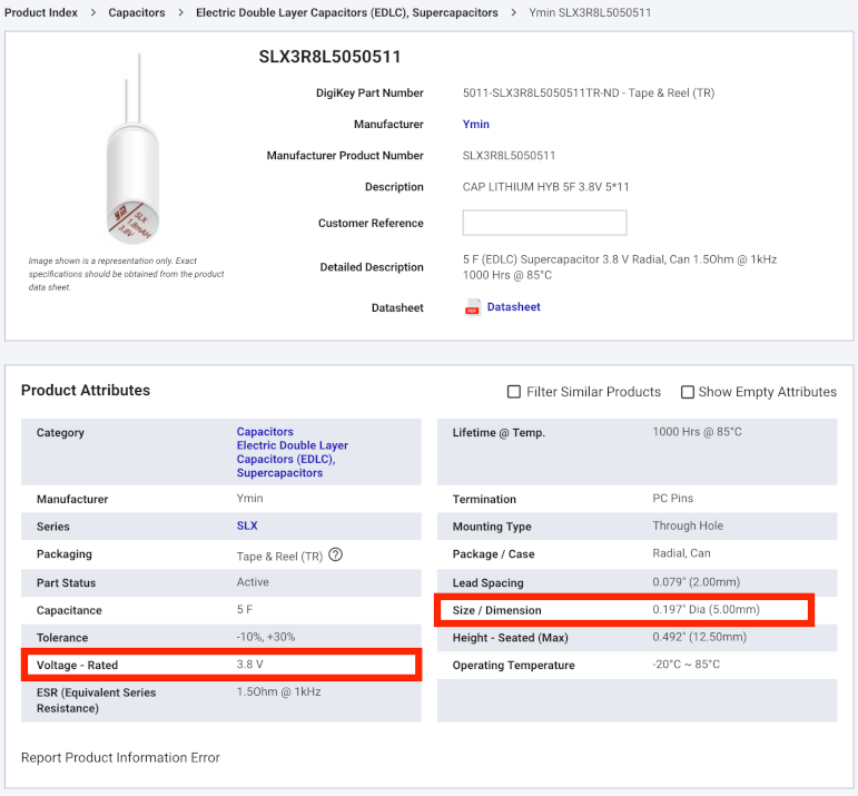
* Replacement supercapacitors (see photo; includes part number but it does not need to be these)
- Rated for very near to battery pack voltage (3.7V listed on my battery pack; double check yours)
- Max 5mm diameter to fit in plastic frame
- 20 F of total capacitance (4 x 5 F wired in parallel) gives about 5 minutes of buffer if unplugged
* Hot glue (optional)
Remove the Battery Assembly
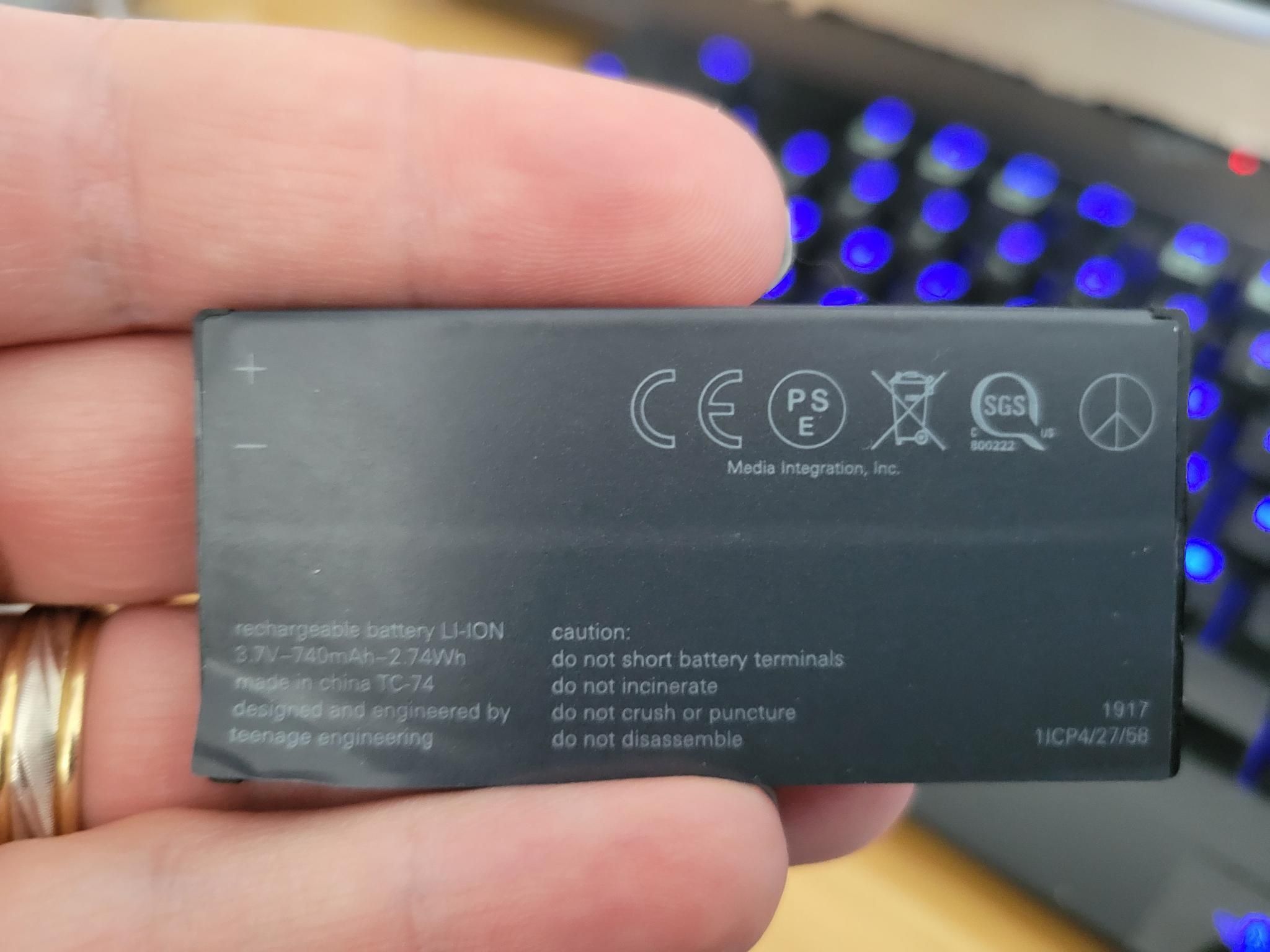
Remove the rear cover of the unit and carefully remove the battery assembly.
Remove the Battery Wrap
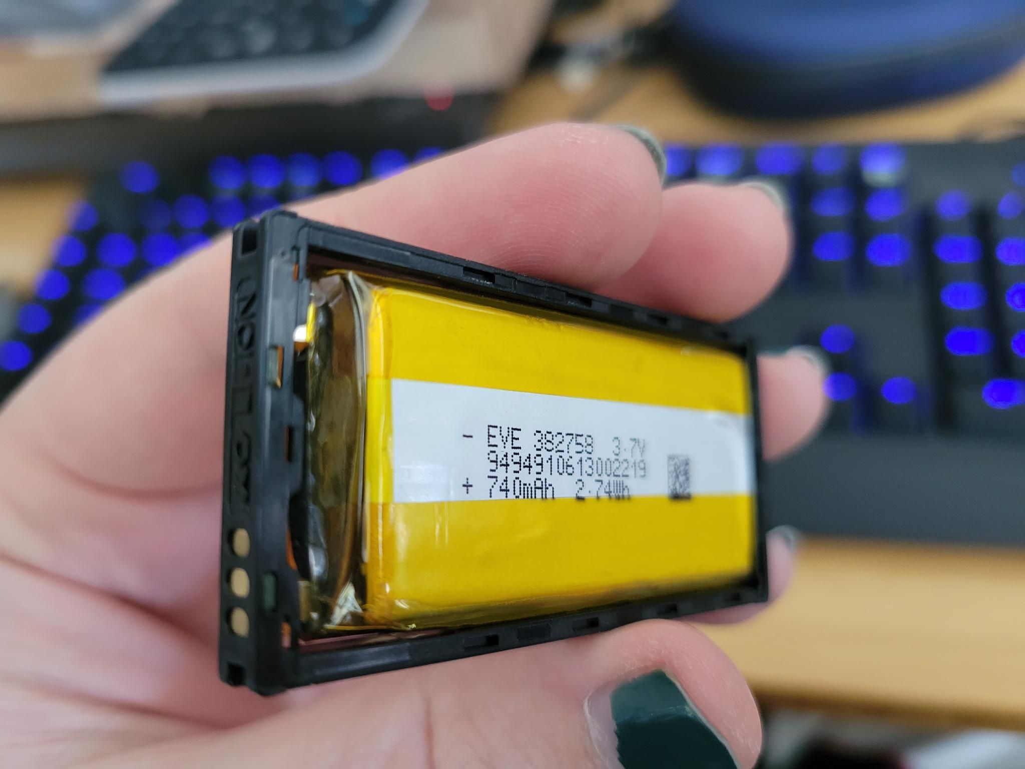
Peel back and remove the informational battery wrap from the assembly.
The thin protective plates will often separate from the plastic frame along with the wrap. If they remain attached, gently lift them free using a non-conductive tool. An old credit card works well for this purpose.
Remove the Battery and BMS Board
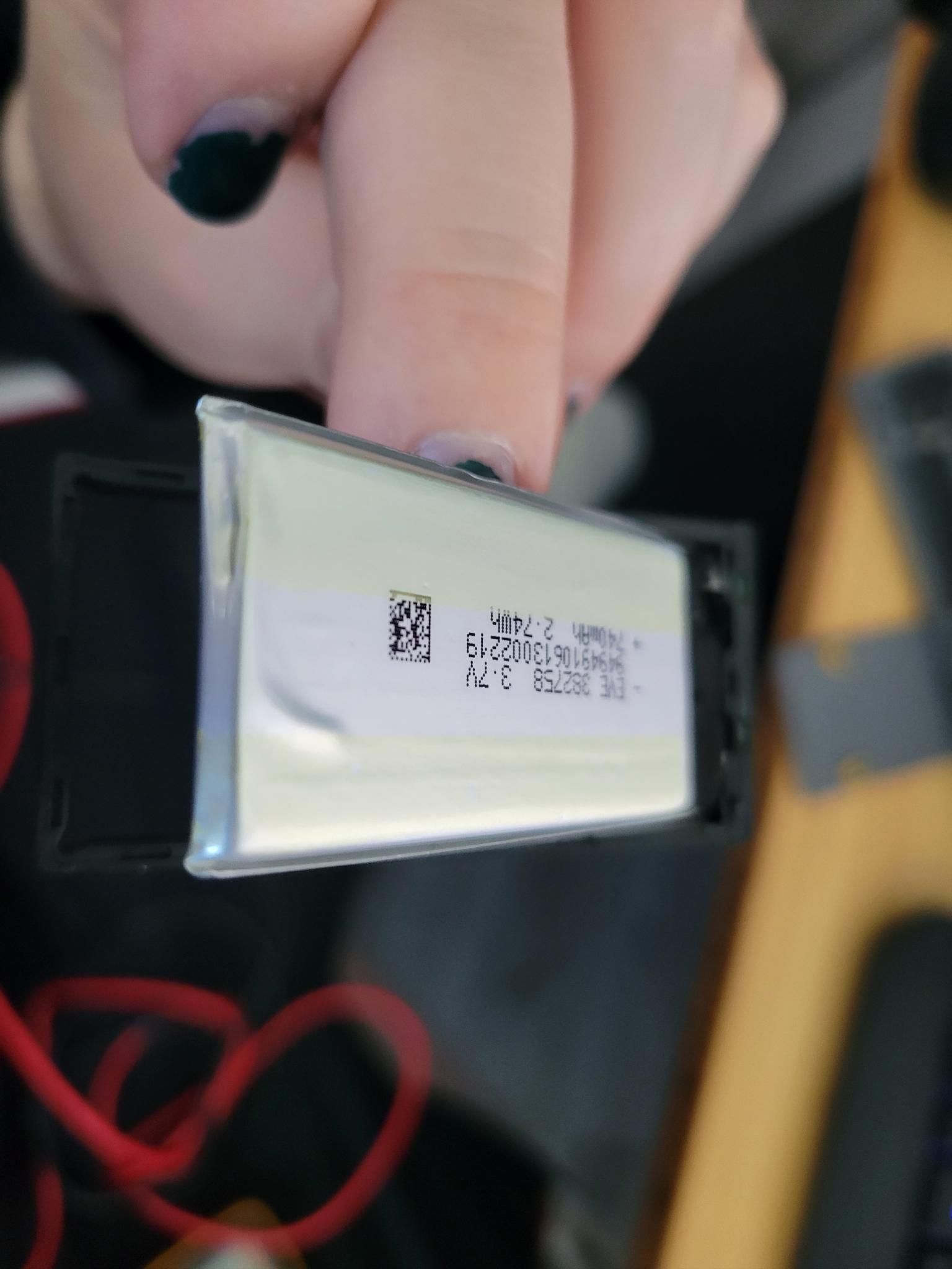
Using a non-conductive tool, gently pry back the retaining tabs that secure the battery and Battery Management System (BMS) board. Remove both components carefully, taking care not to damage the plastic housing or the BMS.
Disconnect and Dispose of the Battery
Cut the battery tabs as close to the BMS solder pads as practical to minimize excess material remaining on the board.
Immediately cover the exposed battery tab leads with electrical tape to prevent accidental short circuits, then take the battery to an appropriate battery recycling facility for disposal.
Install New Connection Posts
Fabricate two short conductive posts from a stiff conductor such as an uncoated paper clip.
Solder one post to the BMS positive (+) pad and the other to the negative (-) pad. Take care to correctly identify and preserve the polarity of the connections before soldering.
Install the Supercapacitors
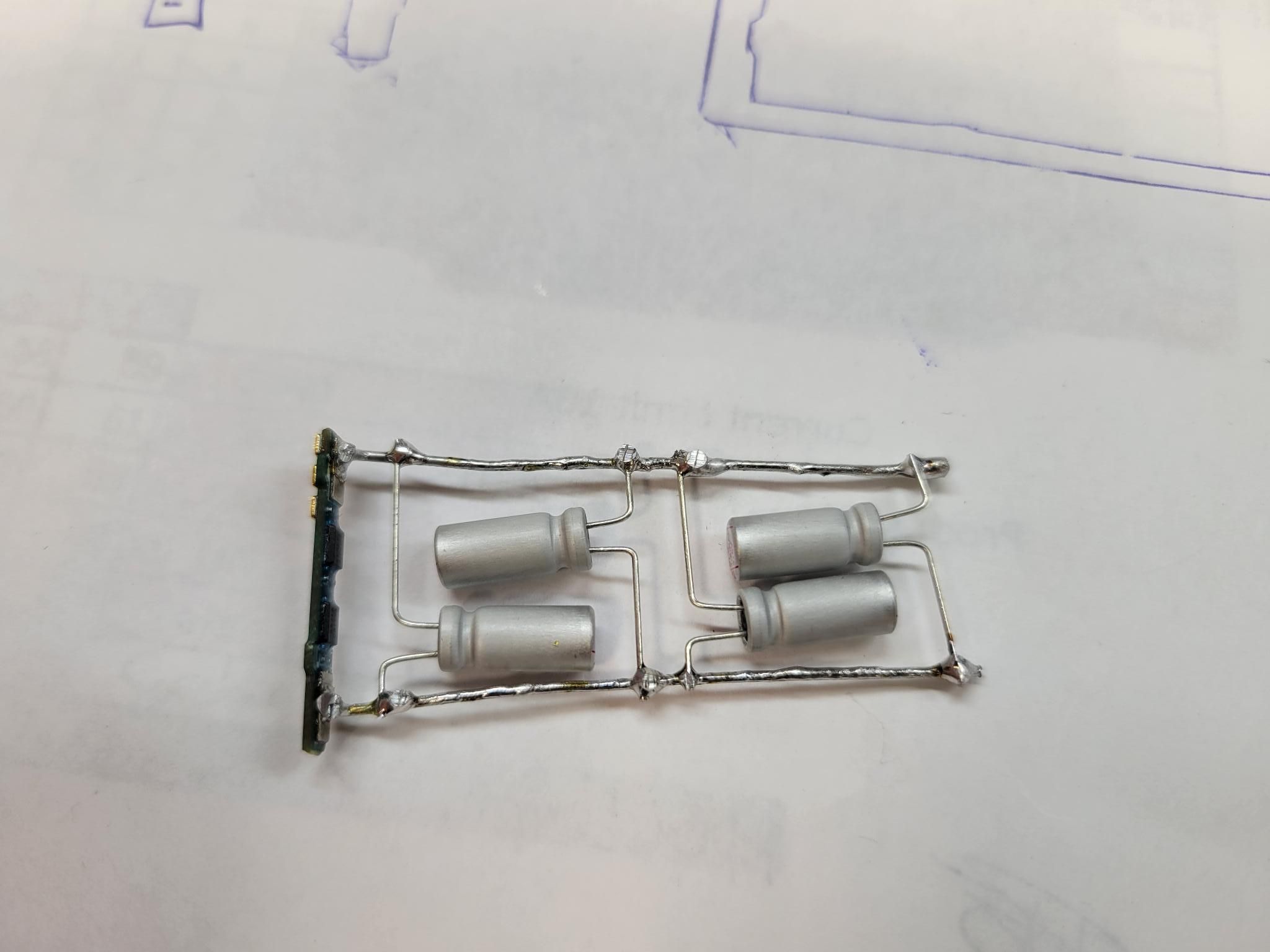
Verify the polarity markings on each supercapacitor before installation.
Solder the supercapacitors between the positive and negative rails, ensuring that each capacitor is connected with the correct polarity. Carefully inspect the assembly for solder bridges, stray wire strands, or other unintended conductive paths, and remove any excess material before proceeding.
Reinstall the BMS
Press the BMS board back into the plastic housing.
If the retaining tabs have become bent or no longer hold the board securely, apply a small amount of hot glue to secure the board in position.
Insulate and Reassemble
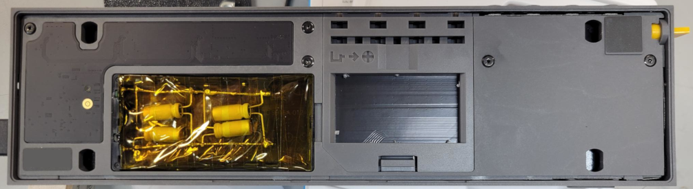
Wrap the exposed portion of the completed assembly with Kapton tape to restore electrical insulation.
Reinstall the completed assembly into the unit and replace the rear cover.
Charge Before Use
Connect the unit to its charger and allow it to reach a full charge before powering it on.
For normal operation, keep the unit connected to external power whenever it is in use. This allows the supercapacitor bank to remain fully charged and ensures reliable operation.