Off-Grid Solar and Hand-Crank Smart Watering System
by 3590638750 in Circuits > Arduino
269 Views, 1 Favorites, 0 Comments
Off-Grid Solar and Hand-Crank Smart Watering System


We've all been that person staring at a drooping plant and whispering, "I'm so sorry, I forgot." If plants could file complaints, "irregular watering" would top the list.
Plenty of us dream of a greener home — a balcony garden, a windowsill of succulents, a corner that actually feels alive. The problem is, plants don't wait for your schedule. Many would-be plant parents are complete beginners who aren't sure when to water, or busy people who travel and simply can't show up for their plants every week. So the green dream quietly turns into a trail of brown leaves.
What if plants could water themselves — with solar power, a bit of elbow grease, and zero wall outlets? That's this project: an off-grid smart watering system that never asks you to plug it in. It harvests energy from a small solar panel and a hand-crank generator — in a real setup, picture yourself pedaling a stationary bike to top up the battery. Sensing, deciding, and watering happen in one self-contained loop, and the whole thing runs on so little power that it survives entirely on what it harvests. No wall wart, no electricity bill, no guilt.
Here's what it does:
- Fully automatic watering. It reads soil moisture, air temperature, and humidity, decides whether the plant is thirsty — and how much — then runs a small pump. All by itself.
- An AI that tunes itself. Every few wake-ups it connects over WiFi and lets a cloud AI review the recent readings, then adjusts its own watering rules to match your plant and climate.
- Brutally low power. The ESP32-S3 spends almost its whole life in deep sleep at around 10 µA, waking for a few seconds every 30 minutes.
- Hand-built, fully open. A custom power PCB I soldered myself, off-the-shelf sensors, and open Arduino firmware — and this tutorial ships every file you need: PCB design, code, and wiring.
Using it is simple:
- It wakes itself every 30 minutes to check the plant, or you can press the button to wake it right now and force a check.
- One RGB LED tells you everything at a glance: green = all good; blue = watering now; a quick white flash = watering finished; yellow = battery low, paused; red = watering failed (pump blocked or reservoir empty); off = battery critically low, responding only to the button.
- Internet is optional. The core watering runs fully offline. It only reaches for WiFi every few cycles to let the AI fine-tune things — no WiFi, no problem, it falls back to its built-in rules.
- And there's a full serial debug interface too: you can wake it over serial, and the menu system gives you command-line control over just about everything.
I'll also walk you through the whole messy, rewarding journey, because the mistakes are where the real lessons live. Here's the roadmap:
- Steps 2–3 — the idea: why this project, and the "power like a plant" thinking behind it.
- Steps 4–10 — the design: each part of the system, from energy harvesting to AI.
- Steps 11–12 — the wiring: connecting sensors, pump, and LED to the ESP32-S3.
- Steps 13–14 — the code: the firmware that reads, decides, and sleeps.
- Steps 15–20 — the power PCB: designing the board that turns sun and cranking into battery power.
- Steps 21–22 — soldering: putting that board together.
- Steps 24–25 — the enclosure: designing and building a home for the electronics.
Your plants get a butler; you keep your wall outlet.
Supplies
Note: We are undergraduates from China, so the software and component models we used may differ from what's available where you live — feel free to swap in any equivalent you can find locally.
Main controller
- ESP32-S3 development board
Power
- Solar panel — 12 V / 7 W
Hand-crank generator — 25 V / 8 W DC motor with crank handle, with a bridge rectifier (AC → DC) with low internal resistance
- Lithium battery — 3.7 V (18650 cell)×2
Peripherals (sensors & actuators)
- Capacitive soil moisture sensor
- Temperature & humidity sensor — DHT22
- Momentary push button
- RGB LED (common cathode)
- Mini water pump — 5 V (USB-powered), driven through a MOSFET driver module (IRF520 or similar)
Basic hardware
- Breadboard
- Jumper wires
- Solid-core copper wire
- Resistors (various values)
Software
- Arduino IDE
- EasyEDA (for schematic, PCB layout, and ordering)
Off-the-shelf modules
- CN3791 — solar MPPT charger
- TP4056 — charge/discharge combo module
- XL6009 — boost converter
- MT3608 — boost converter
- CW2015 — battery fuel gauge
PCB components
- 100 µF electrolytic capacitor ×2 (SMD)
- 1000 µF electrolytic capacitor ×2 (through-hole)
- 1N5819 Schottky diode ×2 (SMA)
- 1N4744A Zener diode ×1 (15 V, DO-41)
- SMBJ24A TVS diode ×1 (SMB)
- 0.5 A resettable fuse ×2 (0805)
- Screw terminal 5.0 mm, 2-pin ×3 (solar, generator, GND)
- PH2.0 connector, 2-pin ×3 (battery)
- XH2.54 connector, 2-pin ×2 (pump, GND)
- XH2.54 connector, 4-pin ×1 (battery monitor → dev board)
- USB-A female connector (side-mount) ×1
- Slide switch (SS-12D10L5) ×2
- 0 Ω resistor ×1 (0805)
- Test point ×1
- 2.54 mm pin header
Basic tools
- Multimeter
- Soldering kit (iron + solder)
- USB data cable (Micro-USB or Type-C, depending on your board)
- Wire stripper
- Tweezers
Architectural model making materials
- PVC foam board
- Wood grain sticker
- PVC foam board adhesive
- Debonder
- Plastic bottle
- Heat Shrink
Code, Schematic and PCB Files
https://github.com/mimeticword/off-the-grid-codes-and-PCB-files.git
(Actually, we should call it Step 0. )The link is provided here for easy reference. It contains the complete code, schematic, and PCB files.
Ideation — From a Green Thought to a Real Plan
Every project starts with a spark. Here's how a single word grew into a real plan.
It began with one word: green — not just a color, but a value: working with nature, not against it.
If we wanted to build something truly green, the first step was obvious: find a role model in nature.
Question 1: What's the greenest thing we know?
Plants. They plug into nothing, buy no batteries, and still grow, adapt, and thrive for years on end.
Question 2: What can a plant actually do that's clever?
We listed what a plant does — and it's quietly impressive. No brain, yet it runs a whole suite of self-regulation:
- It angles its leaves toward the sun to catch the best light.
- It opens and closes tiny pores (stomata) to balance water and CO₂.
- It photosynthesizes — turning sunlight straight into usable energy.
Question 3: What can we borrow from a plant?
Two principles stood out:
- Self-powering. A plant runs on sunshine. Why shouldn't our gadget do the same?
- Self-regulating. A plant continuously senses and responds to its environment — light, moisture, temperature. Could we build a device that does the same, with no human intervention?
Question 4: Where does a plant fall short?
This is where the idea clicked: for all its cleverness, a plant can't water itself. It waits for rain. If the rain doesn't come, it wilts — perfect photosynthesis or not.
That gap is our opportunity.
Our initial plan:
Build a gadget that lives like a plant, but fixes its one weakness:
- Power like a plant — harvest energy from the sun (plus a hand-crank for cloudy days). No wall outlet.
- Regulate like a plant — sense soil, temperature, and humidity, then decide on its own when and how much to water.
- Water itself — the one thing a plant can't do.
In short: a plant that waters itself, powered by the sun.
From Ideation to Plan
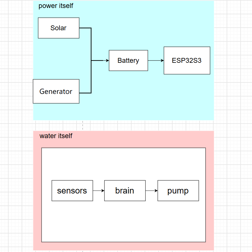
The idea was clear: a plant that waters itself, powered by the sun. But making it happen wasn't as simple as it sounded. So we broke it into functions and worked out what each one needed.
Function 1: Power itself.
Solar was the obvious choice — free, clean, everywhere. But two problems stood out.
First, what if the sun hides for days? We needed a backup as green as the primary. Wind is too bulky; thermoelectric needs a temperature difference we can't guarantee. A hand-crank generator fit the bill — zero emissions, human-powered, and a nice symbolic touch.
Second, what if neither source is steady? Clouds and tired arms happen. So we added a rechargeable battery — a reservoir that stores energy from both sources and delivers steady power to the system. As long as there's charge left, the gadget keeps going.
The power train: Solar + Hand-crank → Battery → System. No wall outlet, no disposables. Just sun, sweat, and a little chemical storage.
Function 2: Water itself.
This broke into three problems.
How do we know when to water? In an ideal world, we'd track everything — plant species, light, wind, pressure, seasons, you name it. But every sensor adds cost, power draw, and logic complexity. We had to draw a line. Two sensors gave us the most insight for the least cost: soil moisture (is it thirsty right now?) and air temperature/humidity (how fast is the soil drying out?). That pair covers both sides — what the plant needs and what the environment is doing. Enough to beat a blind timer by a mile. Other data could refine things, but they're optional.
How do we make sense of the data? Sensors give raw numbers. We need a brain to read them, compare against thresholds, and decide when to water.
How do we deliver the water? A small pump, switched by a simple driver.
That gave us three pieces: sensors → brain → pump. One question left: what brain? A Raspberry Pi is powerful but power-hungry — it'd drain the battery in hours. A basic Arduino is cheap but lacks wireless. The ESP32-S3 sits in the middle: low power, built-in WiFi, enough pins for everything, and costs about the same as an Arduino.
That's the plan: sun and crank in, water out, and a brain in the middle making the calls.
Looking back at what we just laid out, two distinct jobs emerged. The first is about energy, the second is about intelligence. These two jobs barely depend on each other. The brain doesn't care whether the power came from the sun or a hand crank, as long as there's enough of it. And the power system doesn't care what the brain is doing with the energy, as long as it's not asking for more than what's available.
That separation is useful. It means we can design and debug each half on its own. So we officially split the project into two independent loops: the energy loop (harvest, store, deliver) and the intelligence loop (sense, decide, act).
In the steps ahead, I'll walk you through both — but which one you tackle first, and how much time you spend on each, is entirely up to you.
Ready? Let's begin.
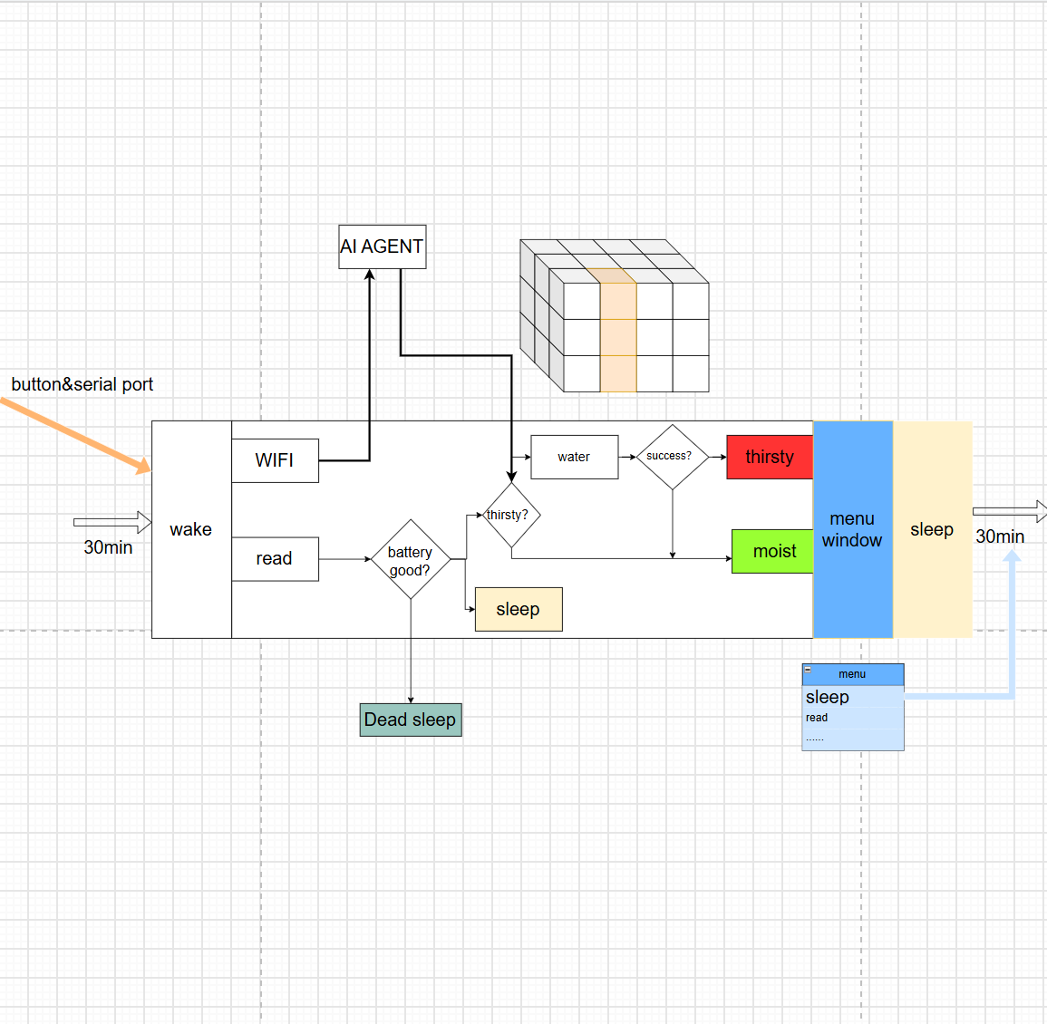
The Core State Machine
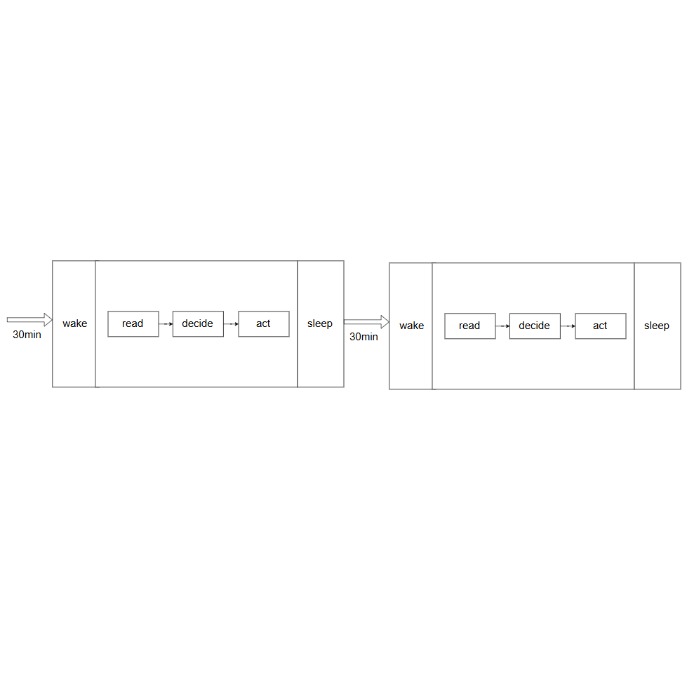
Now we build the intelligence loop, one part at a time: architecture, then hardware, then code. This step is the first part — working out what the brain does.
If you're new to embedded development, here's the short version: instead of a full-blown computer, we're writing software for a tiny chip that does one job — watching sensors, reacting in real time, and sipping power instead of gulping it. We chose the ESP32-S3 for this project: compact (stamp-sized), beginner-friendly (programs in the Arduino IDE), cheap enough for a student budget, and well-rounded — dual-core, built-in WiFi and BLE, plenty of GPIO pins, and a deep-sleep mode that drops current consumption to around 10 µA. Smart enough to decide when to water, connected enough to consult a cloud AI, and efficient enough to run for weeks on one small battery.
And the very first thing the architecture has to respect is power. An ESP32-S3 that stays awake draws tens of milliamps — roughly 40 mA — the entire time it's running. Put it into deep sleep, and that falls to about 10 µA: thousands of times less, which matters a lot when every watt has to come from the sun or your arm.
The good news is that a plant changes slowly. Soil doesn't dry out in a second, and the temperature doesn't swing in a minute, so the brain has no reason to watch around the clock. It can sleep almost all of the time and only check on the plant now and then.
That gives us a simple rhythm: wake up(30 min), read the sensors, decide, act, and go back to sleep.
There's one exception to the rhythm: when the board first powers on, we make it read the sensors immediately, before its first sleep. Otherwise you'd be waiting half an hour just for the first reading.
The Watering Process
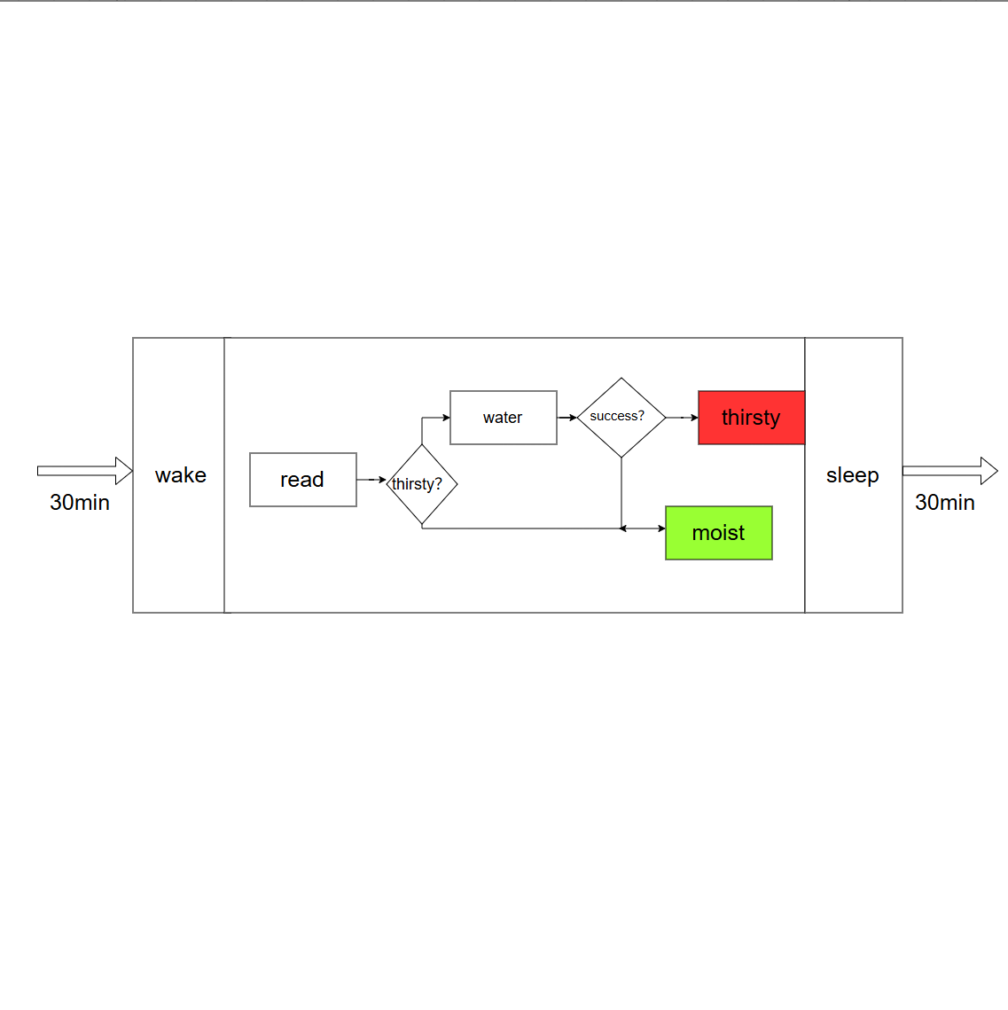
The brain turns on the pump when the soil is dry. The hard part is knowing when to stop.
While the pump runs, only soil moisture changes quickly — temperature and humidity barely move in a minute. So we sample soil moisture every second, and keep the temperature and humidity readings from the wake cycle.
We stop when the soil hits its target. (What that target is, we'll pin down next step.)
But what if something goes wrong — a broken pump, an empty tank, or a sensor that never reaches the target? If we only stop on soil moisture, the pump could run forever. So we add a fail-safe: a 60-second time limit. Stop either way. Better to underwater than to flood the pot or drain the battery.
That's the watering process: pump on, watch the soil, stop when it's wet enough or when the timer runs out. Next, how the brain decides when to start.
The Decision Matrix
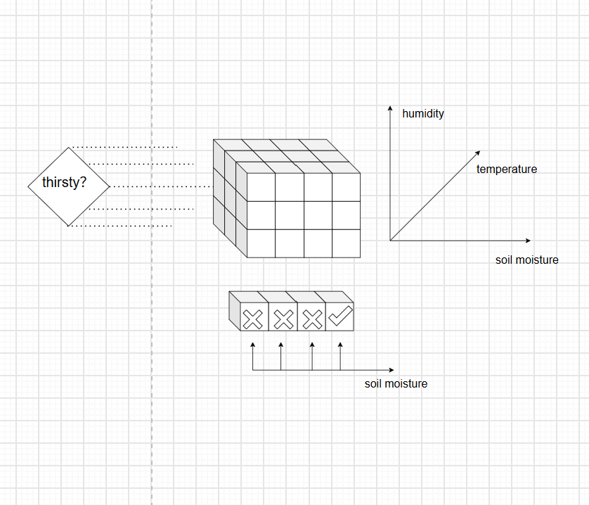
We have three signals: soil moisture, temperature, and humidity. The challenge is turning three messy numbers into a clear yes-or-no.
We split each into levels.
- Soil: four levels (bone-dry to wet).
- Temperature and humidity: three each (hot/mild/cold, dry/normal/humid).
That gives 4 × 3 × 3 = 36 possible states. Each state gets a decision: water or don't. Dry soil in hot, dry air? Water. Damp soil in mild air? Don't. Fill in all 36, and you get a three-dimensional grid — like a Rubik's cube where each small cube tells you what to do.
The brain reads the sensors, looks up which cube it's in, and follows the instruction.
This same grid also answers the question we left open earlier: when is watering "done"? While the pump runs, only soil moisture changes. Picture a column of cubes along the soil axis: as the soil gets wetter, we move down the column. The moment we step from a "water" cube into a "don't water" cube — that's done.
So the decision matrix does two jobs: it tells us when to start, and, walked one cube at a time, when to stop.
Button,Serial Port and Menu
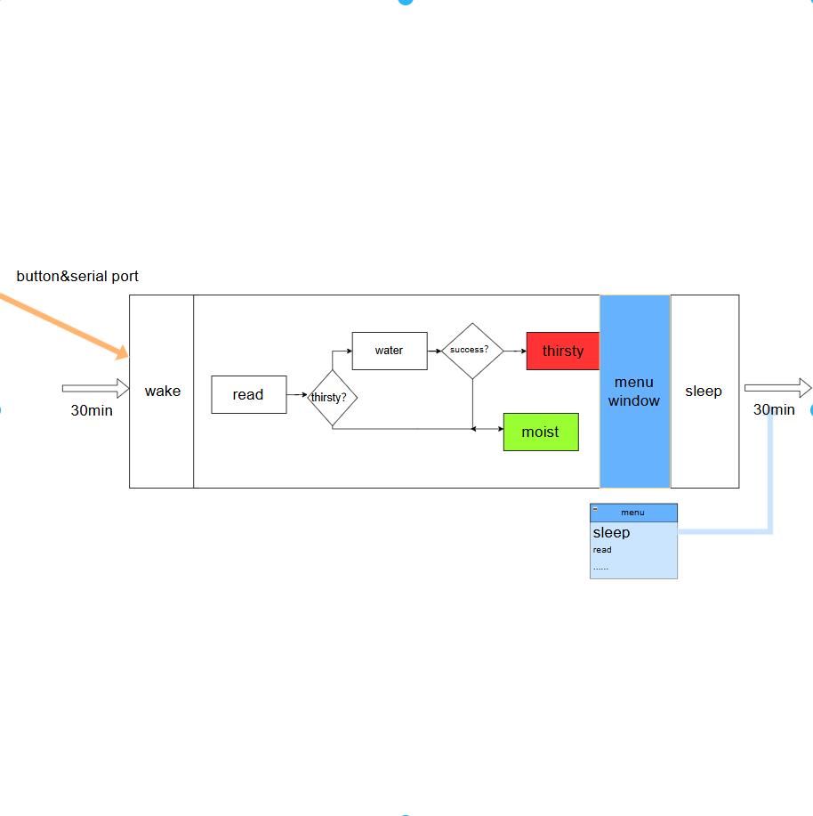
The board runs on autopilot most of the time: sleep 30 minutes, wake, read sensors, check the plant, decide, then go back to sleep. Great for a finished gadget — but miserable for debugging. Waiting half an hour just to run one more test gets old fast.
So we added two manual overrides: a button and a serial port. Either one wakes the board instantly for a fresh reading.
But with two manual triggers and an automatic timer all in play, who's in charge? We set a strict priority: serial first, button second, timer last. Human always beats the program.
That handles waking up. But waking up isn't the same as talking. A button just says "check now" — it doesn't let us ask questions, tweak settings, or test components. For that, we need the serial menu: a command-line window into the machine's brain.
Here's how you get in: every time the board is about to go back to sleep, it pauses for ten seconds. Type anything into the serial monitor during that window, and it opens the menu. Stay silent, and it goes back to sleep on its own.
Once you're in the menu, you're in charge. No auto-sleep — only the sleep command sends it back. A handful of commands cover everything we need:
- read — take a fresh reading
- state — show current thresholds and active watering cells
- run — manually trigger AI adjustment
- p 1 / p 0 — turn the pump on/off
- led R,G,B — set LED color
- help — the one you'll actually remember
- sleep — the only exit
The Battery Check
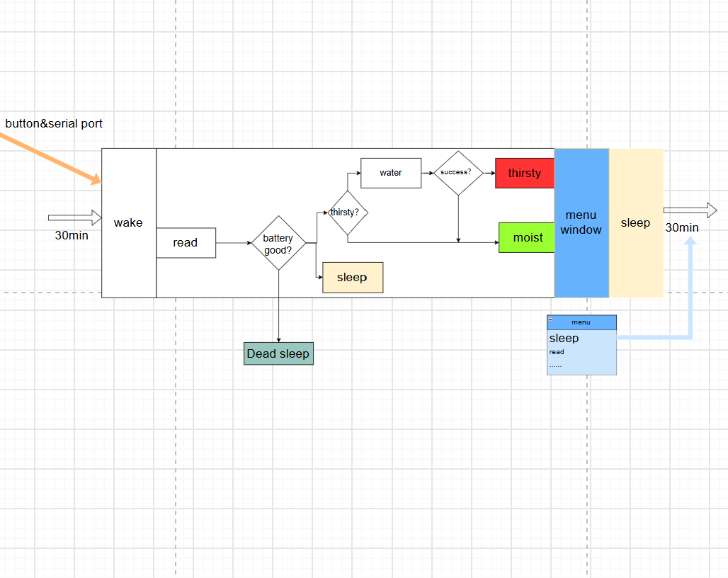
Everything we've built so far assumes the board has power to spare.. But our power comes from a battery, which means it is finite, and one day the battery may run low.
So we add a gate at the very top of every wake: before anything else, read the battery voltage. That single number decides how much of the brain we're allowed to run this time.
There are three possibilities:
- Healthy. The battery is comfortably charged, so the board runs the full state machine: sense, decide, and water if needed.
- Low. There's still some charge left. The board keeps its 30-minute schedule, and its button and serial still work — but it skips watering. Reading sensors is cheap; pumping water is not.
- Critical. The battery is almost empty. Now even the 30-minute timer stops, because waking up costs more than it's worth. The board drops into deep sleep and stays there, waking only on a button press or a serial connection.
Instead of dying suddenly mid-watering — or worse, silently draining the battery below the point where it can ever charge again — the system degrades step by step:
That leaves one final piece: how the board shows which state it's in — using nothing but a single LED.
The Status Light
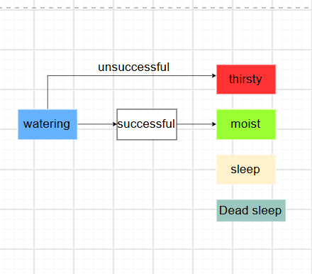
We added an RGB LED that stays lit even in deep sleep — glance at it and you know the state at a glance.
While asleep (the ones that matter from a distance):
- Green — all good.
- Red — something went wrong. Last watering attempt didn't finish in time.
- Yellow — battery running low.
- Off — battery critically low. Nothing left to light the LED.
Briefly while awake:
- Blue — pump is running.
- White flash — watering cycle just completed.
The cost: the LED draws about 6 mA, while the sleeping ESP32 draws just 10 µA — hundreds of times more. On an off-grid system, that's not nothing. But we accepted it. A gadget you have to plug into a computer to read isn't one you'll actually live with. The LED is the one place we spent power to make the system feel alive — and that's worth a few milliamps.
Filtering and Debouncing
Voltage, soil, and temperature/humidity readings all jitter. If that jitter happens right around a threshold, it can cause the system to make wrong decisions—watering when it shouldn't, skipping water when it should, or mistaking a normal voltage for low battery. So we can't trust any single sample. The fix is to read each sensor multiple times and take the median. The median is more robust than the average: one wild glitch can pull an average off course, but the median just treats it as an irrelevant outlier and ignores it. In practice, we sample the soil and the DHT22 three times each, and the battery five times, taking the median of each. The DHT22 also gets a warm-up—its first reading right after deep sleep is often garbage, so we give it a couple of seconds to settle before we start counting. On top of that, all thresholds have a built-in hysteresis gap—a value must cross the line by a real margin before the state changes, so even wobbly readings won't make the system flutter back and forth.
Separately, buttons have a similar jitter problem, but for a different reason. When you press a mechanical button, the metal contacts don't close cleanly once—they bounce, chattering open and shut for a few milliseconds before settling. The chip ends up seeing a dozen "presses" for one real one. We debounce it the same way: read the button, wait a moment, read it again, and only act if both reads agree. One press, one action.
Power and Pins
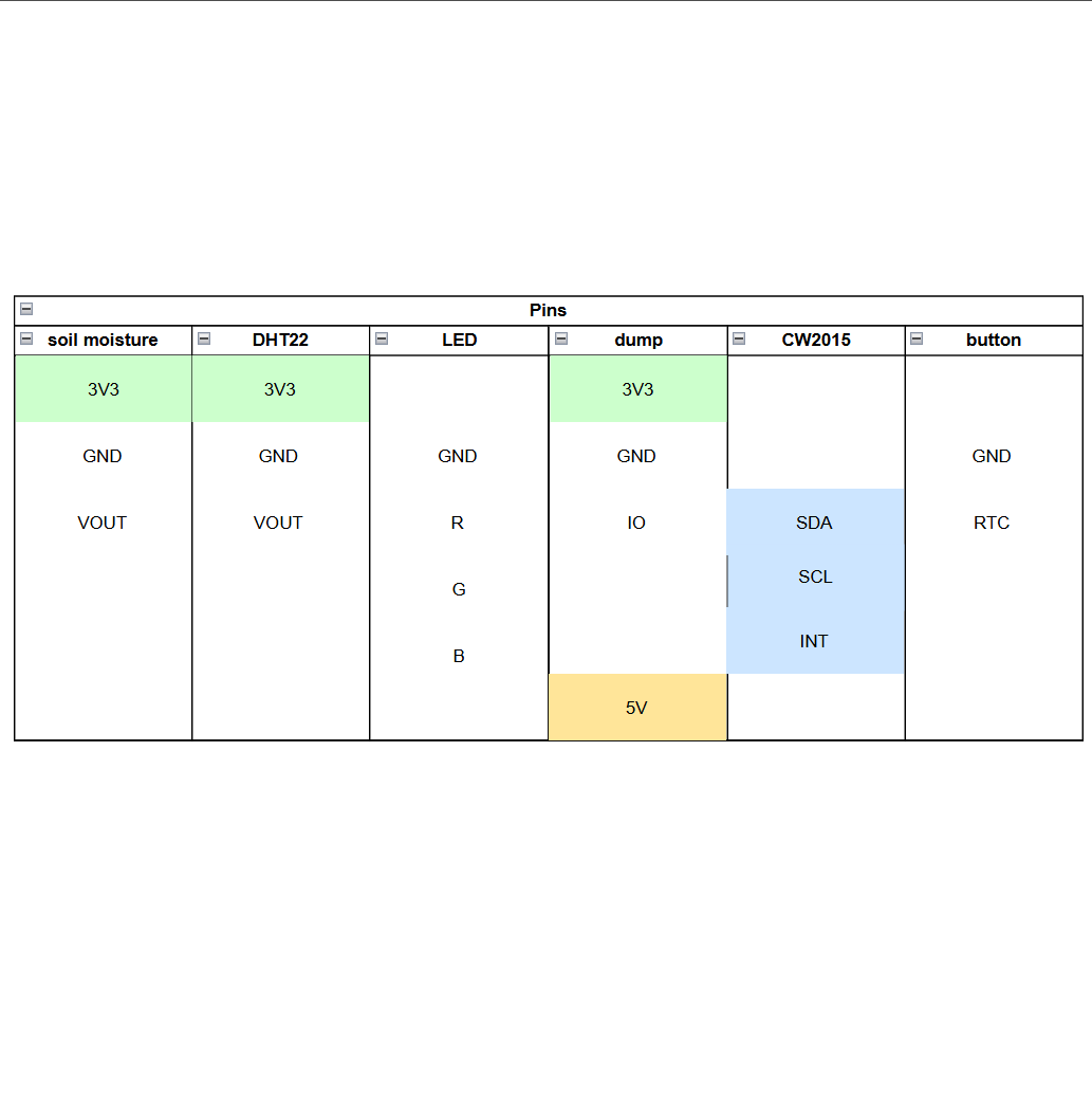
The smart loop is designed, so now we move from planning to building. Before buying components, we need to understand what each one requires. Every external part needs three things: VCC, GND, and a function pin. Some also need extra power.
Good news: all logic components we bought run on 3.3V, so they can share one power rail(you should check yours).
Two exceptions: the battery voltage monitor is already on the power board—only its function pins (SDA, SCL, INT) go to the ESP32. The pump needs 5V and 250mA from a separate supply—never power it directly from the board.
Function pin assignments (special pins first, ordinary ones wherever tidy):
- Soil sensor → ADC pin
- Battery voltage monitor → SDA, SCL, INT (I²C, reports remaining charge)
- Button → RTC pin (wakes the board from deep sleep)
- DHT22 → ordinary digital pin
- RGB LED → three ordinary digital pins
- Pump → ordinary digital pin (switch only), power separate
Before you start laying everything out, here's the pin map we settled on. Ordinary pins can be shuffled to whatever's tidy on your board — the code just needs to match. Two are locked in, and they're explained below.
- Soil sensor → ADC (analog) → GPIO 16
- Battery monitor → SDA → GPIO 8
- Battery monitor → SCL → GPIO 9
- Battery monitor → INT → GPIO 2
- Button → RTC (wake) → GPIO 17
- DHT22 → digital → GPIO 7
- RGB LED — red → GPIO 6
- RGB LED — green → GPIO 5
- RGB LED — blue → GPIO 4
- Pump → switch → GPIO 15
The two that can't move:
- Button → GPIO 17, because it has to be an RTC pin — the only kind that can wake the chip from deep sleep.
- Battery monitor → GPIO 8 / 9 (SDA / SCL), because those are the ESP32-S3's default I²C pins, so Wire.begin() works with zero setup. INT → GPIO 2 is optional — it flags a battery-state change, but we poll the gauge on each wake anyway, so you can leave it unconnected if you're short on pins.
Now we can finally lay everything out on a breadboard.
The Breadboard Build
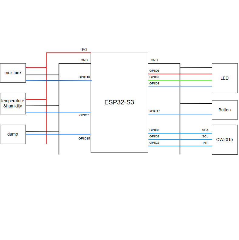


A breadboard is the electronic equivalent of a whiteboard — you sketch your circuit by poking wires into little holes, and if you mess up (which you will), you just yank them out and redraw. No soldering, no permanent mistakes, just pure trial-and-error therapy.
You can follow the simulation wiring diagram provided.
There's one component, though, that deserves a warning before you start: the DHT22. This little temperature and humidity sensor talks over a single data wire, and it relies on a trick that isn't obvious at first. A single-wire bus needs the line to be pulled up — held at a known high voltage by a resistor — so that both sides can signal by tugging it low. The ESP32 has a built-in pull-up, but it's a feeble one (around 45 kΩ), far too weak for the DHT22, which answers with nothing but zeros.
So we add our own: a 4.7 kΩ to 10 kΩ resistor between the DHT22's data line and VCC. That one little resistor is the difference between a sensor that reports real numbers and one that sits there spitting out zeros.
Keep it in mind! If you wire everything up and your temperature and humidity read zero, the first thing to check is whether that pull-up resistor is in place.
May the “Smart” Be With You——Adding AI Adaptation
The machine now runs on its own, but its brain is frozen. The decision matrix we built says "water when the soil is bone-dry and the air is warm," and that's fine — for one season, in one climate, at one altitude. Move the same pot to a humid coast or a dry mountainside, and those fixed numbers quietly stop being right. Rather than hand-write a matrix for every possible situation, we taught the board to reach out to something smarter than itself.
Here's the idea: the board already knows everything it needs — the soil, the temperature, the humidity, and (once it checks a time server) what season it is. So every fifth wake-up, instead of just doing its chores and going back to sleep, it connects to WiFi, sends that little report off to a large language model, and gets back a fresh set of thresholds tuned for right now. It's a distant intelligence quietly guiding the whole thing — about as close to the Force as a houseplant is going to get. The board stores the answers and uses them for the next several cycles.
Setting this up is four steps:
- WiFi — point it at your network.
- An API key — sign up with your favorite LLM (we use DeepSeek) and grab a key.
- The prompt — this is the sneaky part. Every call to an LLM starts with a blank slate, so the prompt has to carry everything: the plant rules, the current thresholds, the recent readings, and the exact format we want back. We wrote ours carefully; borrow it or rewrite it.
- The code — wire the above together.
All of it already works in our project, but it's personalized to us — our phone hotspot, our API key, our idea of a good prompt. The bits you'll want to change live in two files: config_ai.h, for the WiFi password and the API key, and prompt.h, for the prompt itself. Swap in your own, and the machine starts thinking for your garden.
The smart loop is truly finished — it senses, decides, acts, sleeps, and even adapts. But it's still running on a laptop's USB cable, and that's not very "off the grid." Time to fix the power.
Turning the Plan Into Code
The smart loop is designed, the parts are wired on the breadboard, and now the board needs to be taught what to do. We write the firmware in the Arduino IDE — the friendly, free tool that's become the default for hobbyist microcontrollers — and upload it to the ESP32 over a USB cable.
Every major idea we've designed — sleep rhythm, decision matrix, watering window, menu — maps to a separate file in the code. The structure is clean; you'll find your way around. One file does the heavy lifting: the config. Every number you'll ever need lives there in plain sight — the 30-minute sleep cycle, how many samples to average per reading, the 10-second menu window, and every threshold we agonized over (soil dry/wet, hot/cold, humid/dry, battery low/critical).
So you have two paths forward.
The easy one — grab our code and flash it straight onto your board. It's already written, tested, and working.
The more interesting one — write it yourself. And here's where our earlier planning pays off twice over: the same keywords we used to describe each idea are now a ready-made prompt. One thing the prompt won't do: pick your numbers. You'll set all of those yourself. The silver lining: changing how the thing behaves later is just editing the config and re-flashing.
Just don't expect it to be flawless. AI-generated code is like a first sketch — broadly right in direction, full of small surprises. You will debug: a pin that's off by one, a sensor that reads zero until you remember that pull-up resistor, a sleep command that doesn't actually sleep.
Now that the code is uploaded and behaving, the machine is finally running autonomously.
The Power Problem
Now for the other half of the project—the power loop. This is what makes the system truly self-sufficient. We'll follow the same rhythm: design the circuit, draw it onto a board, and solder it together.
But two loose ends from the smart loop are waiting for us here.
- The pump still needs its own proper supply.
- The board needs a real way to read the battery's voltage—the code asks for it every wake-up, but the hardware doesn't exist yet.
Both belong to the power loop, so let's keep them in mind.
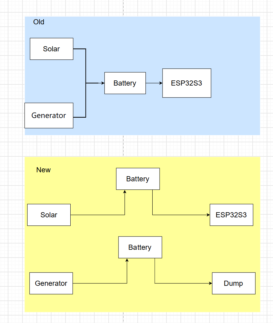
Our first power plan looked fine on paper—until we looked closer. It had two serious flaws.
- First, we'd tied the solar panel and hand-crank generator together in parallel. This looks convenient, but it's risky. The higher-voltage source backfeeds into the lower one. Even with Schottky diodes, the lower source just sits idle—power is generated but wasted. The hand-crank generator, when running unloaded, turns all its energy into heat in the coil—prolonged idling can cause overheating, insulation damage, and burnout. Worse, the two sources have completely different characteristics (solar is quasi-constant current, the generator fluctuates wildly), making it nearly impossible to find a single charging IC that handles MPPT, protection, and response for both.
- Second, we'd let the battery charge and discharge at the same time. A single lithium cell has only one terminal—current flows one way at a time. But the real danger is subtle: if a charger fills the battery while a load drains it, the charger can't tell which electrons go where. It misreads the battery, keeps pushing current, and overcharges it. For lithium, overcharging means heat, swelling, and eventually fire.
So we tore it apart and rebuilt it as two clean, separate paths, each guarded by a switch: one where the solar panel charges the battery and the battery feeds the board, another where the battery feeds the pump. Charging and discharging never happen at once, and every source gets its own lane.
That's the skeleton. Next, we have to make the voltages actually match.
Matching the Voltage
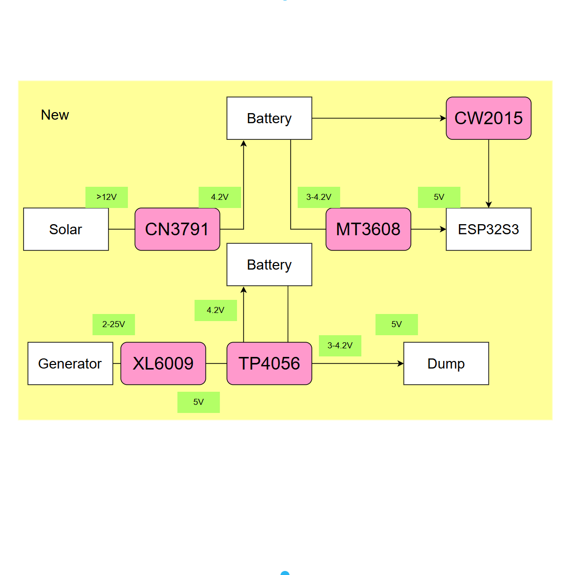
We rebuilt the power plan into two clean paths, but there's a small problem hiding in plain sight: nothing in this project runs at the same voltage. Here's the damage, path by path.
The solar side:
- Panel — rated 12 V, but its peak can push past 24 V under a bright sun.
- Battery — charges at a gentle 4.2 V.
- Board — wants 5 V or more.
The crank side:
- Generator — 2 to 25 V, rising with how hard you turn it.
- Battery — charges at 4.2 V.
- Pump — wants 5 V.
Connect any two of those directly is mismatching, so we need voltage conversion modules. You can use the ones we picked or choose your own, but check each module's input and output range carefully, because they're not all the same.
Four of ours are converters, changing one voltage into another:
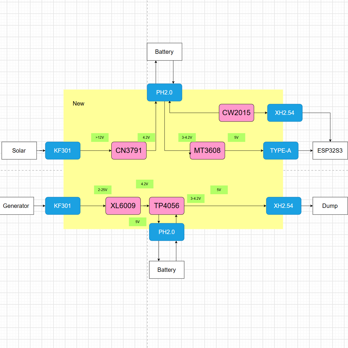
- CN3791 — solar panel (12 V, spiking) → 4.2 V, charging the cell the right way.
- MT3608 — battery 3.0–4.2 V → 5 V for the development board.
- XL6009 — generator 2–25 V → 5 V, taming the crank down to something usable.
- TP4056 — and here's the fun one. Remember how we said a battery can't charge and discharge at once? It turns out there's a TP4056 module with a built-in load-sharing circuit that handles exactly that safely. It sits between the XL6009 and the pump, managing the battery's charge and discharge in one go, so it replaces the switch we'd otherwise need. The other path keeps its switch.
And one of ours is a reader, not a converter, so it gets its own line: the CW2015, a tiny battery fuel gauge that measures the cell's voltage and reports it back to the board — which finally closes out that second loose end from before.
With those in place, the finished circuit reads like a map:
Solar panel (12 V+) ──▶ CN3791 (charge) ──▶ Battery (3.7 V) ──▶ MT3608 (5 V) ──▶ Board
Generator (2–25 V) ──▶ XL6009 (5 V) ──▶ TP4056 (charge+discharge) ──▶ Pump
Battery ──▶ CW2015 ──▶ Board (reads the voltage)
One honest note about the pump: the battery tops out at 4.2 V, but the pump is rated for 5 V. In theory, we could add another boost converter to give it exactly what it wants. In practice, that extra module would cost us efficiency — every conversion burns a little power, and in an off-grid system, a little adds up fast.
So we tested it. Turns out this little pump runs just fine at 3.3 V — a bit slower, sure, but still moves plenty of water. The trade-off was clear: accept a slightly slower pump, or burn more battery to give it full speed. We chose the former. The pump hasn't complained yet, and neither have the plants.
Protection and Refinement
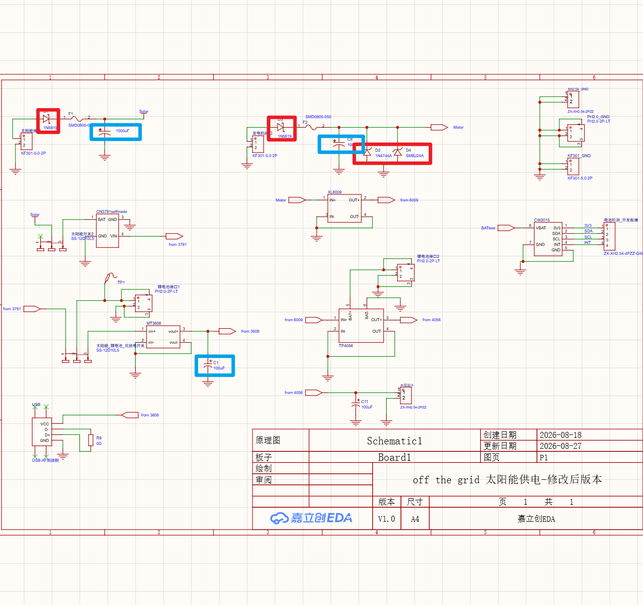
The circuit works in theory, but theory doesn't protect hardware. One wiring fault or voltage spike can destroy the panel. Thus, we add protection and tuning before final implementation.
The protectors:
- Fuses (self-resetting, 0.5 A) — tripwires that pop on a short and reset when things cool down.
- Schottky diodes — one-way doors for current. They stop power from flowing backward into a source, so a stronger source can't pour current into a weaker one.
- A master switch — the simplest safety device there is: a big manual off switch that disconnects everything while you're tinkering.
- A zener diode (1N4744, 15 V) — A 15 V zener diode clamps the panel voltage — a brute-force fix that wastes power, but keeps things safe during testing. Remove it after validation to recover efficiency.
The refinements:
- Electrolytic capacitors (100 µF and 1000 µF) — reservoirs that smooth the generator's jerky output into something steady.
- Ceramic capacitors — tiny filters parked next to the modules to catch the high-frequency noise the big electrolytics can't reach.
- A TVS diode (SMBJ24A) — a fast-acting spike suppressor. It catches the sharp, brief overvoltage transients that a zener is too slow to stop.
- An extra ground terminal — a dedicated point where every ground meets, keeping the return path clean and the whole system happy.
These protections and refinements can be seen directly in the provided schematic diagram
Match Before You Mate
Connectors are one thing — but what if the board itself doesn't have the right holes for them? That's where footprints come in.
I made this mistake myself before: bought the wrong connectors and they didn't match the pin headers. They looked the same, but the pitch was different — one 2.0 mm, the other 2.54 mm — so they wouldn't fit. Just like VCC, connectors come in all kinds. You have to get the matching right. Here are the common ones we used:
- Screw terminals (KF301) handle the bare wires — the solar panel and the generator plug in here, because their wires are thick and a screw gives a solid, no-solder grip.
- XH2.54 is the classic 2.54 mm header, the same spacing as a breadboard, and it's where the pump and the battery-monitor cable live.
- PH2.0 is its tighter 2.0 mm cousin, and the battery box plugs in here.
- USB is the one everyone already owns, for charging and talking to the board.
The takeaway: don't memorize our list — check your parts. Look at each wire's pitch, and make sure your board's terminals match. A 2.0 mm plug will not fit a 2.54 mm socket no matter how hard you press. Trust me.(╥﹏╥)ノ゙.
Drawing You Own Footprints
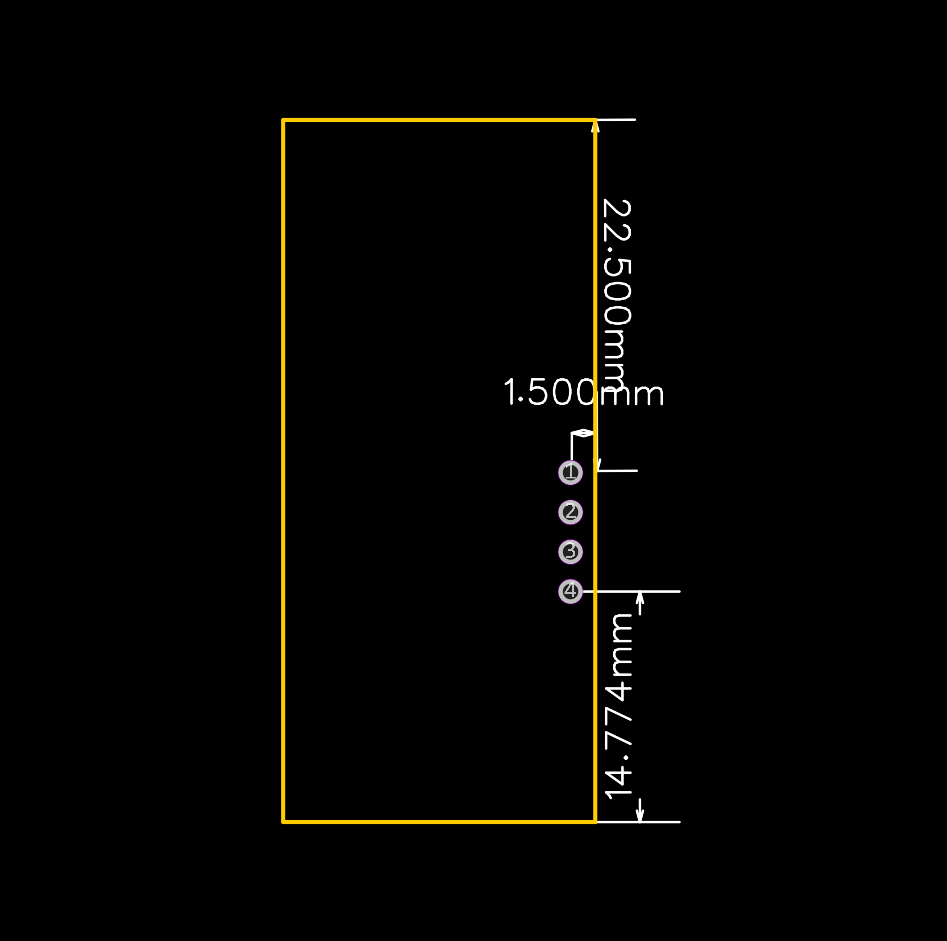
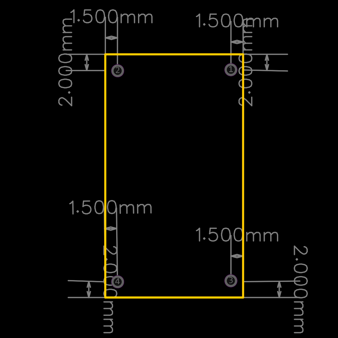
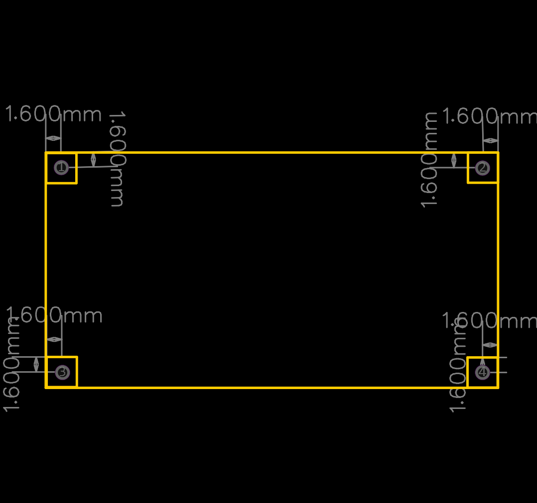
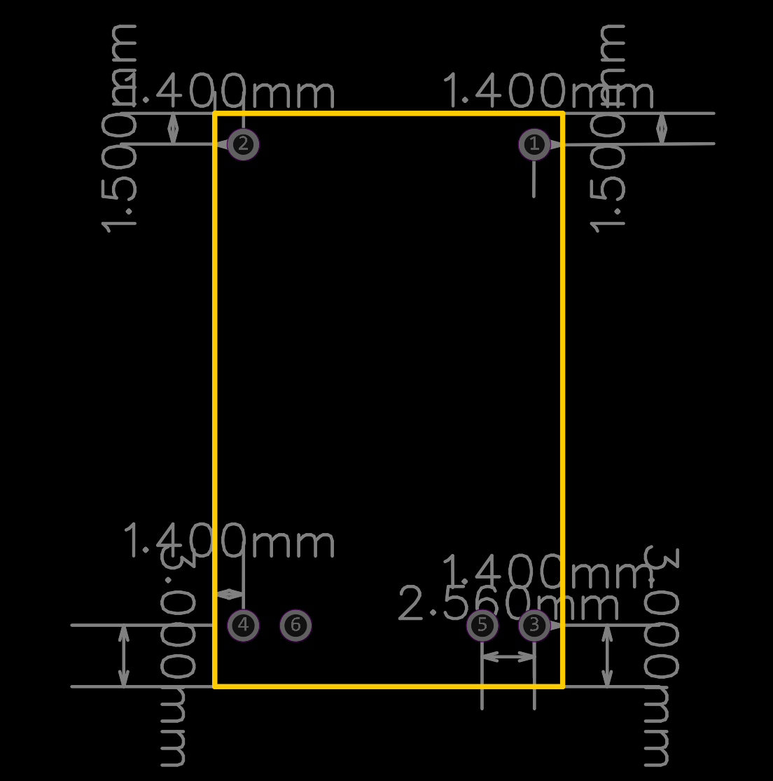
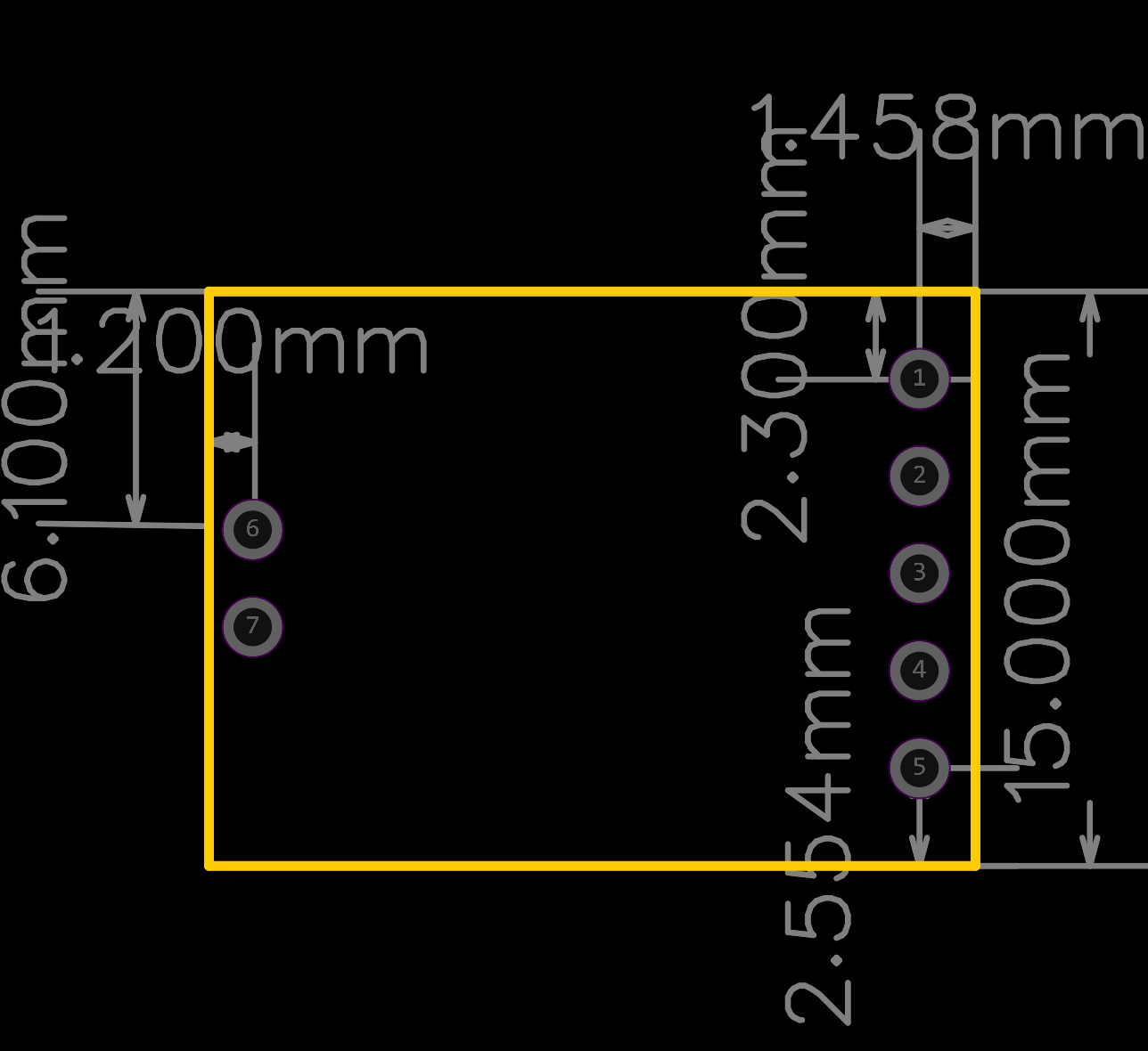
Here's the thing nobody tells you about PCB design: your parts won't always be in the library. EasyEDA has thousands of footprints, but search for something like a CN3791 and you'll only get bare chips instead of modules(only modules can fulfill the function). So you have to draw your own.
It's not that hard. A footprint is just a drawing of where the pins go. You only need the part's size and pin spacing. Grab the datasheet, measure, and draw.
Feel free to use our footprints — but only if your part matches ours exactly. If not, just redraw.
Two things will get you. First, pin numbers: the footprint must match the schematic symbol. If they don't, the software won't warn you, and the board will be wrong. Second, spacing: even a fraction of a millimeter off, and the module won't fit. So you have to be cautious!
PCB Layout Guidelines
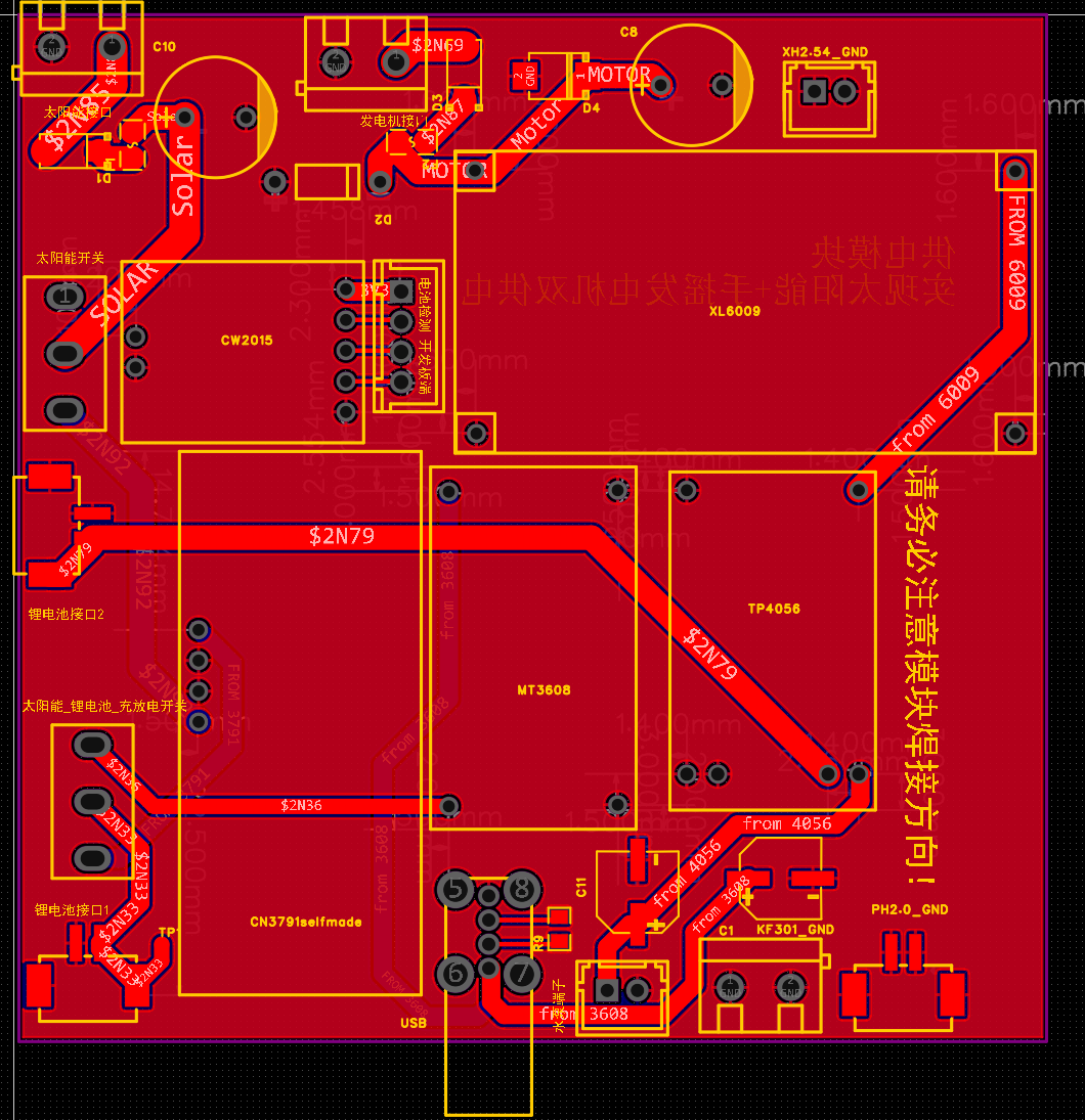
Now turn the design into an actual board. Two drawings: schematic (electrical connections) and PCB (physical layout). Use ours or draw your own.
If drawing your own PCB, keep these in mind:
Trace width — the charging path can hit 1A, so give those traces at least 0.5mm. For power traces, 1mm is safer—wider means lower voltage drop and less heat.
Copper pours — fill unused areas with ground copper on both layers and stitch them with vias. This lowers return impedance, cuts noise, and helps with cooling.
Heat management — the CN3791 runs warm while charging. Leave a copper pad under it with thermal vias to pull heat to the other side. More copper around it means a longer life for the chip.
Placement — keep noisy stuff (switching nodes, inductors) away from sensitive stuff (feedback dividers, analog sense lines). Keep high-current loops short and tight to reduce radiated noise.
Decoupling capacitors — place the 100nF ceramic cap as close as possible to each IC's power pin, with its ground side straight to the ground plane. Bulk caps (100µF, 1000µF) go near the input and output.
Size — smaller is cheaper, but leave 2–3mm between components for hand soldering.
The above lists and briefly describes common PCB requirements. You can search online for more detailed requirements, as well as the PCB recommendations and limitations found in each module's datasheet.
How well you follow these requirements will largely determine whether your power board design works properly. This is especially true for sensitive components like voltage regulator modules, where certain requirements directly affect functionality. That's exactly one of the main reasons we chose integrated modules instead of designing everything from scratch. To be honest, we even have some doubts about our own power board—if you spot any issues or come up with a better solution, feel free to reach out to us!
One more thing: EasyEDA runs a monthly free prototyping offer, so your first board can cost you nothing. The catch is it has to fit within 100×100mm—ours does.
Get all that right, and you're ready to place your order. Click the button, wait a week, and a shiny board shows up at your door—ready for soldering. And don't forget to grab that monthly free prototyping coupon before you check out if you use EasyEDA.
Buying the Parts
A perfect schematic is useless if its parts don't exist. Before ordering, make sure every symbol maps to a real part number that's actually in stock — in a package you can actually solder. Then use our BOM below, or build your own.
Or skip the whole headache and use our bill of materials:
Off-the-shelf modules
- CN3791 — solar MPPT charger
- TP4056 — charge/discharge combo module
- XL6009 — boost converter
- MT3608 — boost converter
- CW2015 — battery fuel gauge
PCB components
- 100 µF electrolytic capacitor ×2 (SMD)
- 1000 µF electrolytic capacitor ×2 (through-hole)
- 1N5819 Schottky diode ×2 (SMA)
- 1N4744A Zener diode ×1 (15 V, DO-41)
- SMBJ24A TVS diode ×1 (SMB)
- 0.5 A resettable fuse ×2 (0805)
- Screw terminal 5.0 mm, 2-pin ×3 (solar, generator, GND)
- PH2.0 connector, 2-pin ×3 (battery)
- XH2.54 connector, 2-pin ×2 (pump, GND)
- XH2.54 connector, 4-pin ×1 (battery monitor → dev board)
- USB-A female connector (side-mount) ×1
- Slide switch (SS-12D10L5) ×2
- 0 Ω resistor ×1 (0805)
- Test point ×1
- 2.54 mm pin header
Soldering


The board comes back from the factory, shiny and empty. Now it's your turn. Soldering sounds scary, but it's just hot glue with metal — and like hot glue, you'll burn a finger or two before you get the hang of it.
Order matters: surface-mount first — the tiny fuses, diodes, and ICs that sit flat like a carpet. Then through-hole: the big caps, terminals, switches. Shortest to tallest, always. Nothing's worse than a giant capacitor blocking your iron from a tiny resistor hiding behind it.
For surface-mount, tweezers and flux are your best friends. Place the part, tack one pin to hold it, then solder the rest. And don't drown the pads — a solder bridge between two pins is the classic "oops," and it usually means you got a little too generous with the solder.
Through-hole is simpler: poke the leads through, bend them slightly so they don't fall out when you flip the board, solder from the back, and snip the excess. Satisfying, like trimming nails.
Screw something up? No panic. Bridges disappear with solder wick or a sucker; a dull, grainy joint just needs a reheat with a dab of flux and it'll flow shiny again. Magic, but with smoke.
One last thing: the CW2015's BAT+ pin needs a jumper to the testpoint — that's how the board reads battery voltage. Easy to miss, absolutely maddening to debug later when everything else is already soldered. Check it twice. Future you will be grateful.
Make sure to verify that the module is functioning correctly prior to soldering. After soldering, conduct circuit tests immediately to confirm that no abnormal conditions, such as short circuits, have occurred.
The 1.5 Volt Mystery: What We Learned About Grounding


After soldering the power board, we tested it with the hand-crank generator. The generator spins up to 10 V with no load, so we expected smooth sailing. Instead, three bad things happened at once:
- The board only reached 1.5 V.
- The crank got noticeably harder to turn than with no load.
- The wires got hot.
All three together point to one thing: a short circuit. A big current was flowing somewhere it shouldn't.
Hypothesis #1 — a solder bridge. We assumed the XL6009 boost converter's input had shorted during soldering. So we desoldered it, bought a fresh one, confirmed the new chip worked on its own, and this time mounted it on header pins with flying wires instead of soldering it straight to the board. Powered it up — and got the exact same 1.5 V, hard crank, and hot wires. So it wasn't the soldering.
The accidental discovery. While re-testing, we happened to wire the generator's negative straight to the XL6009's IN- pin, and left IN- disconnected from the board's shared ground. Suddenly everything worked: the crank turned freely, and the output came up to a clean 5 V.
That was confusing, because IN- and OUT- are the same node inside the module (we measured it). "Disconnecting" IN- shouldn't have changed anything — yet it fixed everything.
What was actually going on. Here's the lesson: ground is not 0 Ω. When the generator's noisy, pulsing current returned through the shared ground plane, it made that "0 V" reference bounce around. The boost converter relies on a clean ground to time its switch — with a dirty reference, the control loop misbehaved, the switch stayed on too long, the inductor saturated, and the input effectively became a short. Hence 1.5 V, hot wires, and a stubborn crank.
The fix wasn't really floating the ground. It was giving the return current a clean, dedicated, short path straight to the converter's IN- pin, instead of letting it flow through the shared ground pour. That's star grounding — a single-point return.
Three rules we took away:
- Star-ground the generator. Run its negative directly and separately to the converter's IN-, not through the shared ground plane.
- Keep the loop small. Twist the generator's two wires together to shrink the loop area and cut down on noise pickup.
- Keep input capacitance close. A low-ESR electrolytic (100 µF) plus a small ceramic right at IN+/IN- gives the boost converter a soft buffer against the generator's high impedance.
Our final fix: don't solder the XL6009 straight to the board — mount it on pins and connect it with flying wires, and wire the generator directly to the converter. Not elegant, but it works, and it's far easier to debug.
Enclosure Design and Materials


Before cutting anything, I asked two questions: what does this box need to do? and how big should it be?
What does the enclosure need? Three things, in order:
- Easy to show off. This is a display piece, not a hidden gadget — the plant and the electronics should both be visible.
- Reasonably pretty. It'll live on a wall or shelf, so it shouldn't look like a pile of parts.
- As simple as possible. No complex joinery or laser-cut parts — just flat panels I can cut by hand.
Research. I looked at wall-mounted planters and letterboxes online for inspiration. The shape that kept coming out on top was the classic wall-mounted mailbox: a sloped roof that sheds water, three walls, and an open front you can see into.
The design. A sloped-roof box, open at the front, with three walls — basically a tiny mailbox for a plant. The slope isn't just for looks: it lets the solar panel sit at an angle and keeps rain from pooling on top.
How big? Sizing came from the layout, not the other way around. First I decided where everything would sit:
- Breadboard and ESP32-S3 dev board — side by side, left to right, mounted on the back wall.
- Power board — on the floor, toward the right.
- The plant — on the floor, toward the left.
- Water pump — outside the left wall.
- Hand-crank generator — out front, or outside the right wall.
- Solar panel — on the roof.
Then I measured the modules and settled on these panels (all in cm):
- Floor: 25 × 25
- Back wall: 25 × 30
- Side walls (×2): a trapezoid — 25 along the bottom, 30 up the back, 25 up the front, sloped top between them
- Roof: 25 × 25.9 (the sloped face)
Material. PVC foam board (Sintra/Foamex). It's light, cuts cleanly with a craft knife, is stiff enough to hold its shape, and is a common go-to for enclosures and props.
Tools and supplies:
- PVC glue + glue remover (debonder)
- Clear tape
- Strong double-sided tape
- Scissors and a utility knife
- Brass standoffs (to mount the boards with a little air gap)
- Ruler and pencil
The finish. A wood-grain adhesive film over the outside turns plain white foam board into something that reads as a proper little wooden mailbox.
Enclosure Assembly


Time to actually put the box together. Assembly order matters here — it's much easier to mount everything while each panel is still flat and reachable than to fish wires into a finished box.
1. Back wall first. Mount the dev board and breadboard onto the back panel (screws or brass standoffs give them a small air gap). Then glue the back wall to the floor at a right angle. These two pieces define the whole box, so make sure that corner is square.
2. Left side wall. Drill a hole and pass the water pump through, so the pump ends up outside the left wall with its hose free. Do this before gluing the wall on — the hole is much easier to cut flat.
3. Right side wall. I'd planned to hang the hand-crank generator outside the right wall, but its wire came up short. Rather than splice in an extension, I moved it to the front of the box instead. The right wall just stays plain.
4. Roof. Don't glue the roof flush against the back wall — leave a small gap at the top. That gap is where the solar panel wire and the DHT22 wire slip through to the inside.
5. Remaining modules. Fix the LED, the soil moisture sensor, and their wires in place. Route the wires along the panels and tape them down so nothing dangles or gets pinched when the last walls go on.
6. Plant and power board. Set the plant on the floor (left) and the power board on the floor (right), then connect the power board up to everything else.
7. Adjust and power on. Do a final check on the wiring, then power it up. Watch the LED, run a test wake cycle, and tweak anything that looks off.
Thanks for Reading
You made it to the end — thank you for sticking with us.
This whole thing was built by me and two friends(雒丹语&吴浩源) in about a month, so it's far from perfect. If you spot a mistake, or know a better way to do something, please feel free to point it out — we'd genuinely love to hear it.
And here's hoping we all end up a little greener. 🌱