"Old School" 7 Segments Mechanical Wifi Clock (and More...)
by Etienne Leroy in Circuits > Clocks
1268 Views, 6 Favorites, 0 Comments
"Old School" 7 Segments Mechanical Wifi Clock (and More...)
)
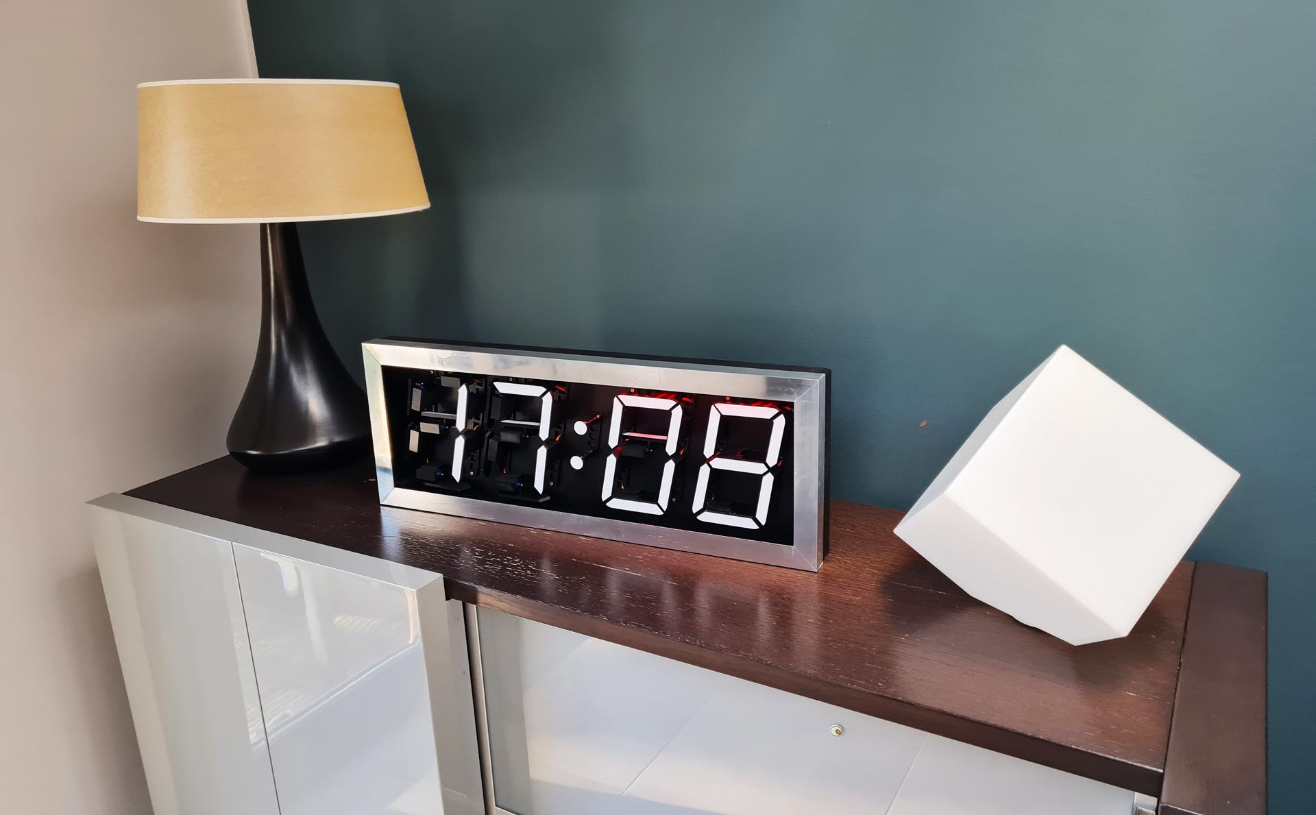
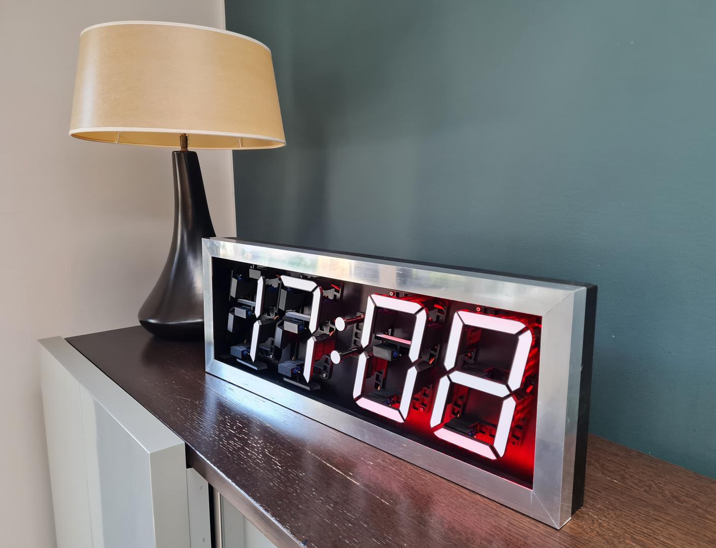


Born in the 70's, I was constantly in visual contact with these 7 segments displays. Watches, calculators, alarm clocks, etc...These were almost the only screens we looked at.
I made this one as a tribute to the many "7 segments displays" that rocked my childhood and further.
Hope you'll enjoy making yours.
Supplies

Here's what you need, to build this 7 segments Display panel :
3D PRINTED PARTS
- 3D Printer (or access to a 3D Printer)
- Black PLA and White PLA
ELECTRONICS :
- 28x MicroServo SG90
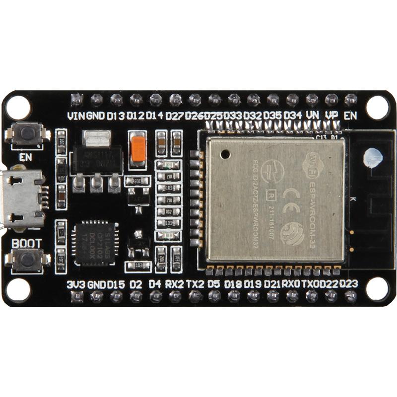
- ESP 32 wifi Board
- 2x PCA9685 PWM Boards
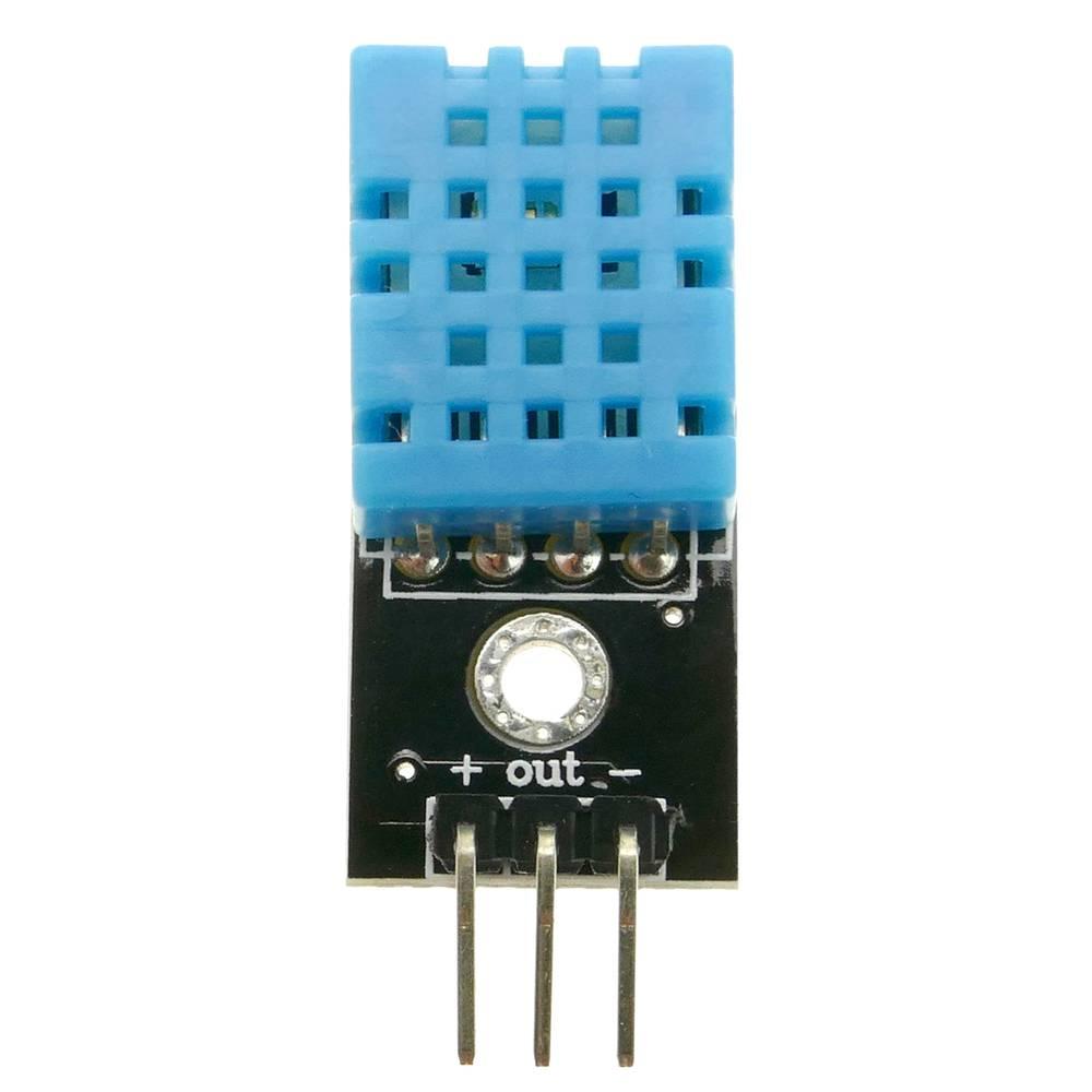
- DHT11 Temperature and Humidity sensors Board
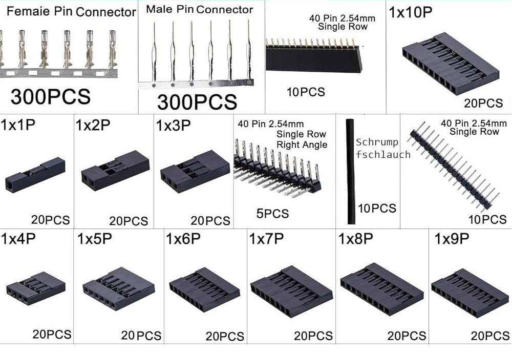
- Male and female Dupont Connectors
- Wires
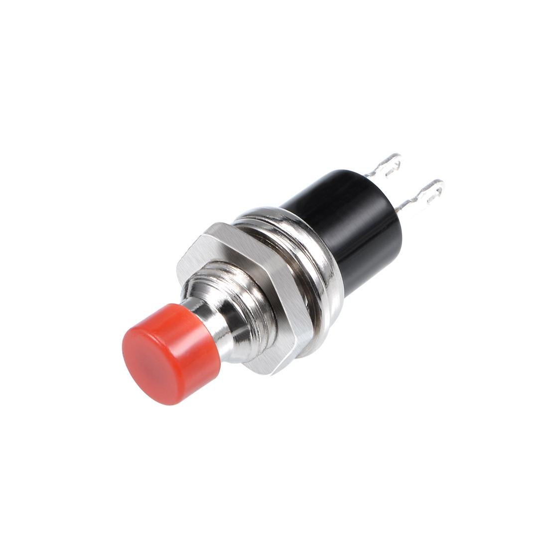
- 2 push buttons
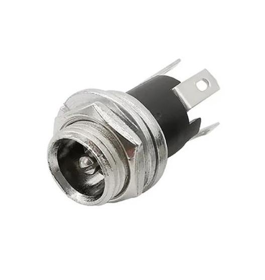
- Power connector
- Power Supply 5V (at least 20A)
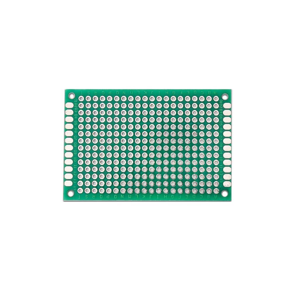
- Raw PCB
- 108 Leds Strip WS2812B
THE CASE :
9mm thick Black Medium Wood (670 mm x 240 mm) for the wood base.
5mm thick Plywood
For the Front Panel :
- 670mm x 65mm x2
- 250mm x 65mm x2
- 30mm x 30mm Aluminim Corner (1.5mm thick) 2 Meters long
- M3 x 25mm screws + bolts x4
For the Rear Box :
- 600 mm x 40mm x2
- 180mm x 40mm x2
- 610mm x 180mm x1
M3 x 15mm screws + bolts x18 (for the 4 PLA bases and the Dots Support)
MISCELLANEOUS :
- Wood Glue
- Cyano Glue
- Hot Glue
- Solder Iron + Tin
- Circular Saw
- Jig Saw
- Dremel + Metal Cutting discs
- 2mm Pencil Lead (for marking holes to drill)
- Aluminium polish
3D Printing

First you'll need to print the different parts of the display, which is 4 times the same unit.
For 1 Unit : (x4 for the total display)
- Base x1 (Black PLA) (0.2mm layers with supports).
- Segment_1 to 7 (Black PLA) (0.15mm layers) / Print these upside down with supports.
- SegmentWhite_1 to 7 (White PLA) (0.15mm layers) / Print these upside down, no supports).
- Arm x5 (Black PLA) (0.15mm layers, no supports) / Print as shown on image#5.
- Arm_2 x1 (Black PLA) (0.15mm layers, no supports) / Print as shown on image#5.
- Arm_6 x1 (Black PLA) (0.15mm layers, no supports) / Print as shown on image#5.
- Servo_Cover x7 (Black PLA) (0.2mm layers, no supports) / Print these upside down.
For the Dots :
- Dot x2 (Black PLA) (0.15mm layers) / Print these upside down with supports.
- Dot_White x2 (White PLA) (0.15mm layers) / Print these upside down, no supports.
- Dots_Support x1 (Black PLA) (0.2mm layers, no supports)
For the Front frame and Rear box : (Non visible, so whatever the PLA color)
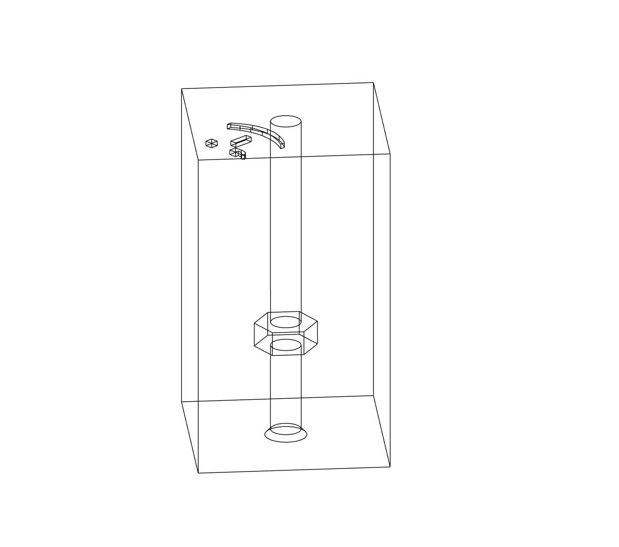
- Wedges x8 (PLA) (0.2mm layers) / Smiley face up, no supports. (see image#1)
- Corner x4 (PLA) (0.2mm layers, no supports.)
- 45_degrees_tool x1 (PLA) (Optional) (0.2mm layers, no supports.)
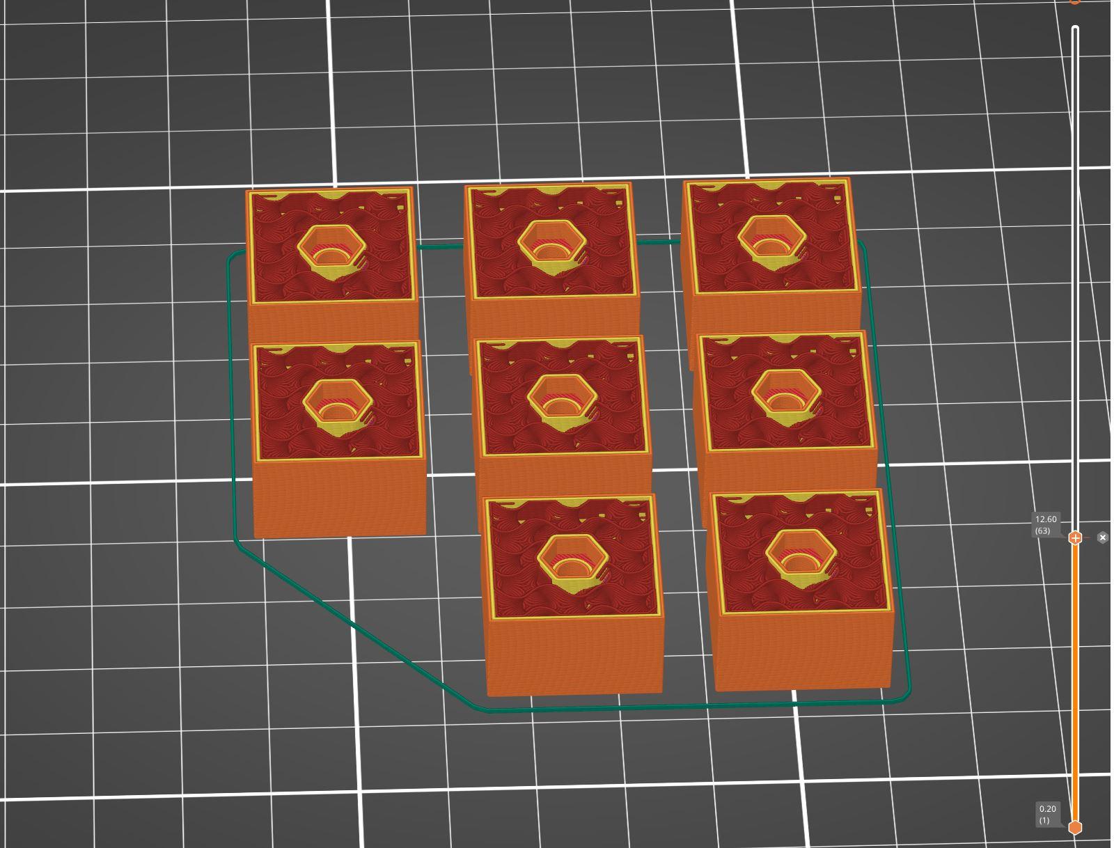
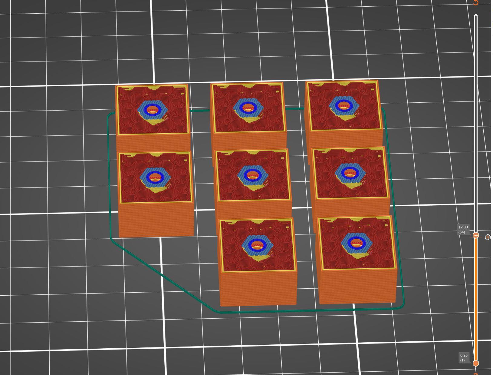
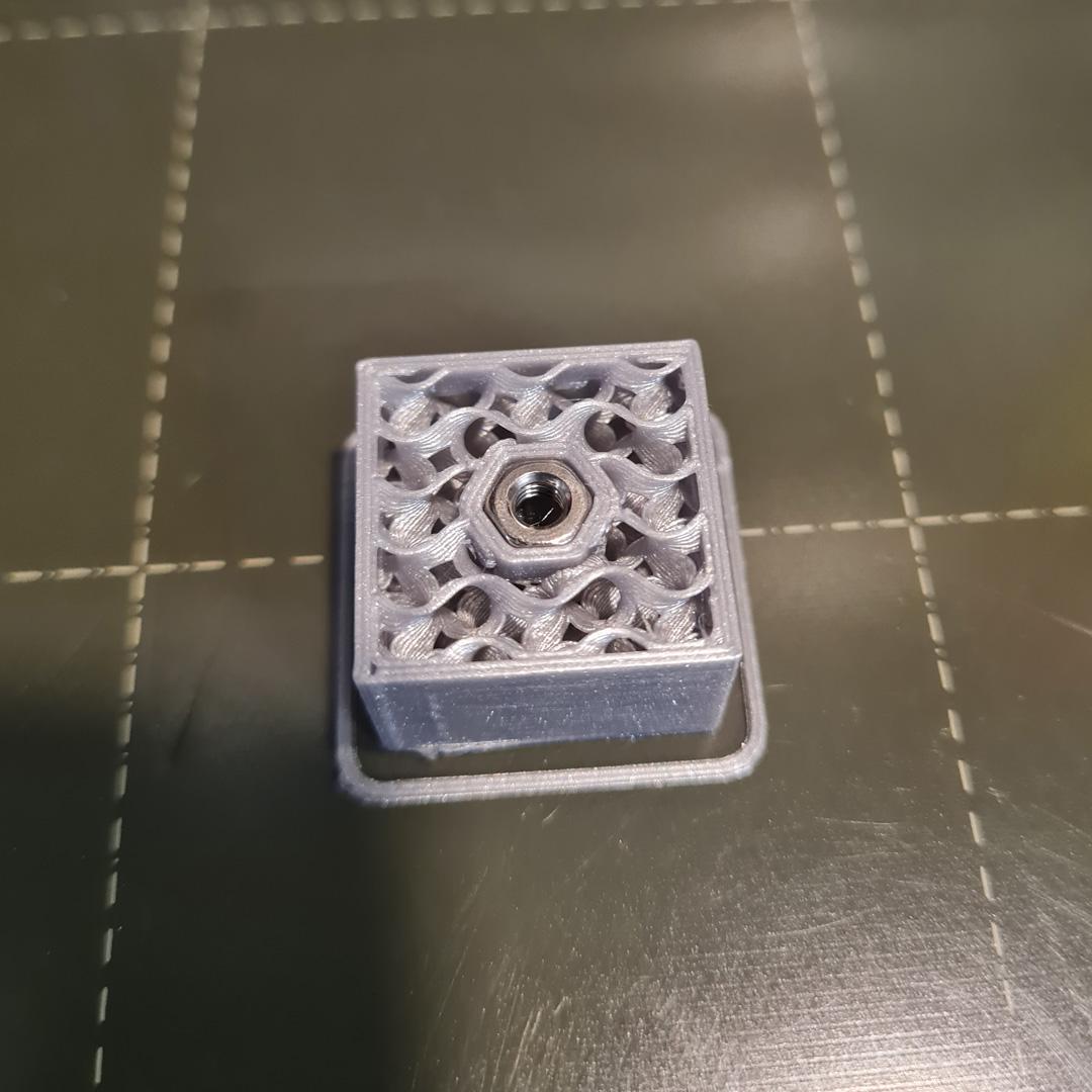
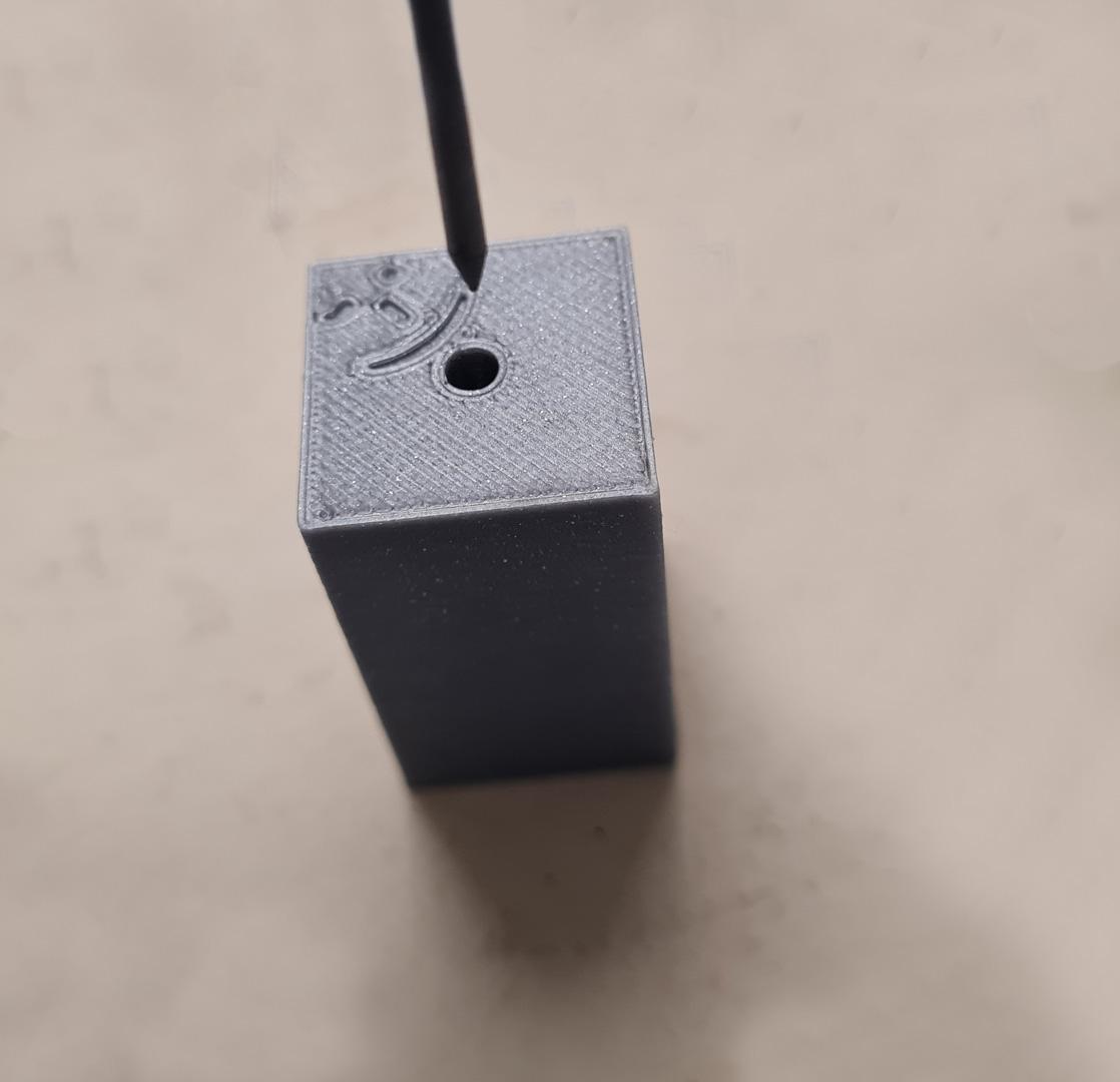
You'll have to insert a pause in the printing of the 8 Wedges in order to insert M3 bolts inside the prints. (see Images#2, #3 and #4). The pause to insert is at the end of layer 63 if you print at 0.2mm/layer.
If you don't know how to do so, you can download the G-code with the pause just below. >>>Wedges_0.2mm_PLA_Paused.gcode
Once everything is printed, remove all the supports and clean the prints.
For the Wedges, ensure to clean inside the hole (with a long nail for ex) before screwing the M3 screws.
Downloads
The Wood Base
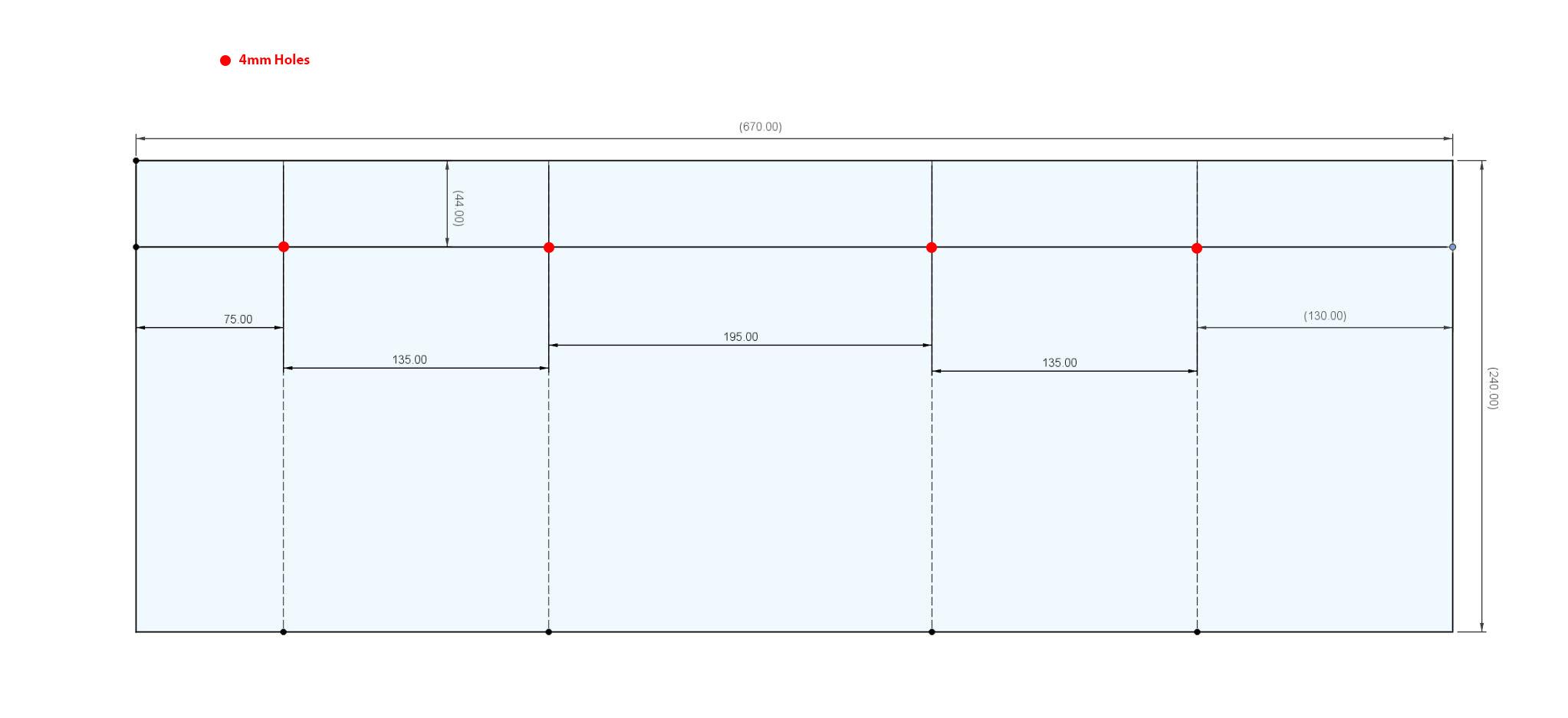
9mm (Black optionnal) MDF wood. Dimensions : 670 mm x 240 mm
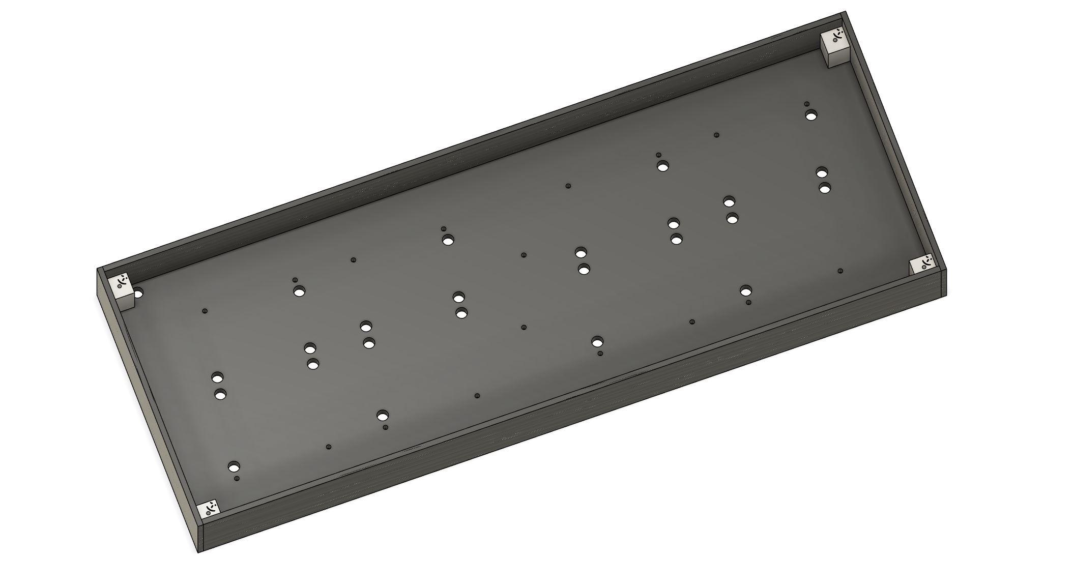
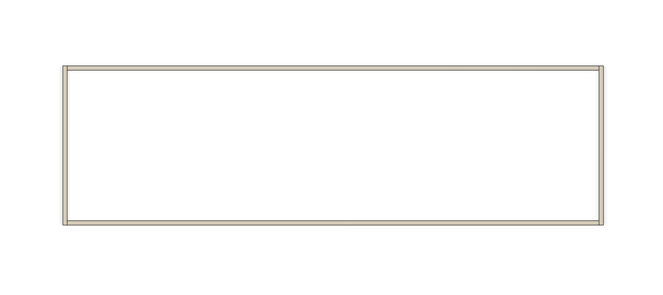
Draw a line, parralel to the length, at 44mm of the top. (see Image#1)
This will be the line to center the upper holes of the PLA bases.
1st hole : 75mm from the left edge of the base
2nd hole : 135 mm from the 1st hole
3rd hole : 195mm from the 2nd hole
4th hole : 135mm from the 3rd hole
These are the holes for the upper left holes of each PLA base. Drill at 4mm diameter.
Insert screws and bolts to place the 4 bases.
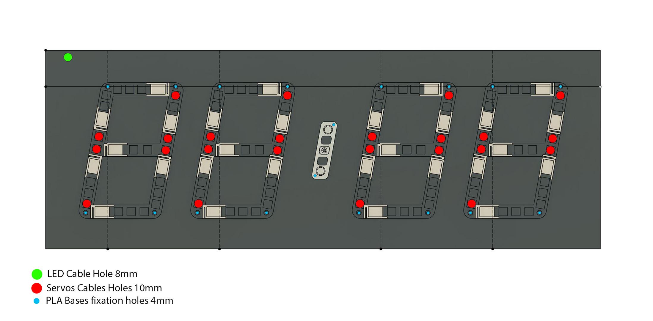
Now, align the PLA Bases and mark all the 3 other holes per unit and drill . The upper right hole must be on the 44mm line. (Image#2)
Then, we have to drill 10mm holes for the servos cables as shown on the Image#2.
Drill a hole near the upper left corner for the LED cable to pass through the wood base. (Image#2)
When everything is in place, drill 2 holes, 4mm diameter, centered, for the Points_Support. (Image#2)
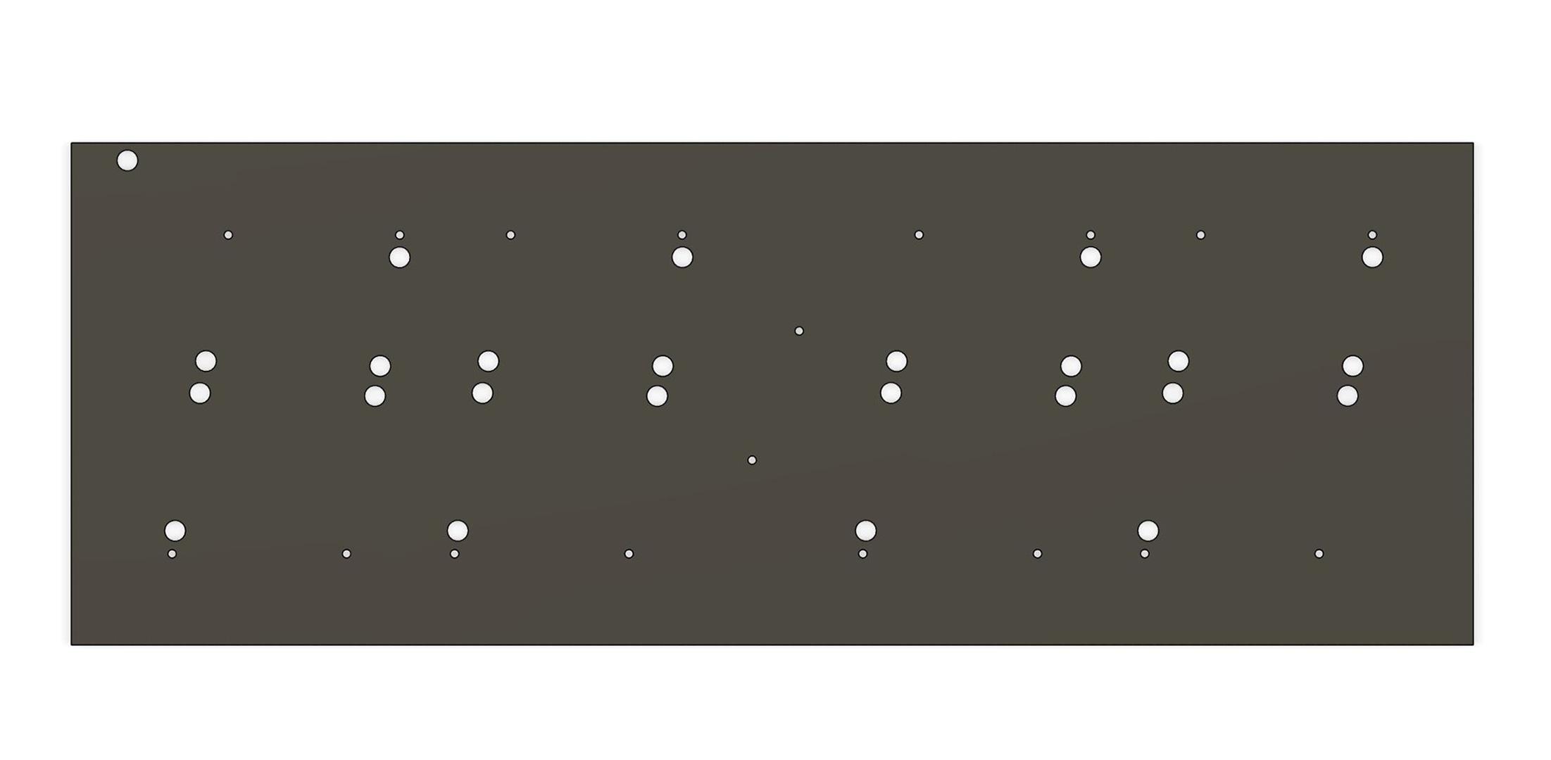
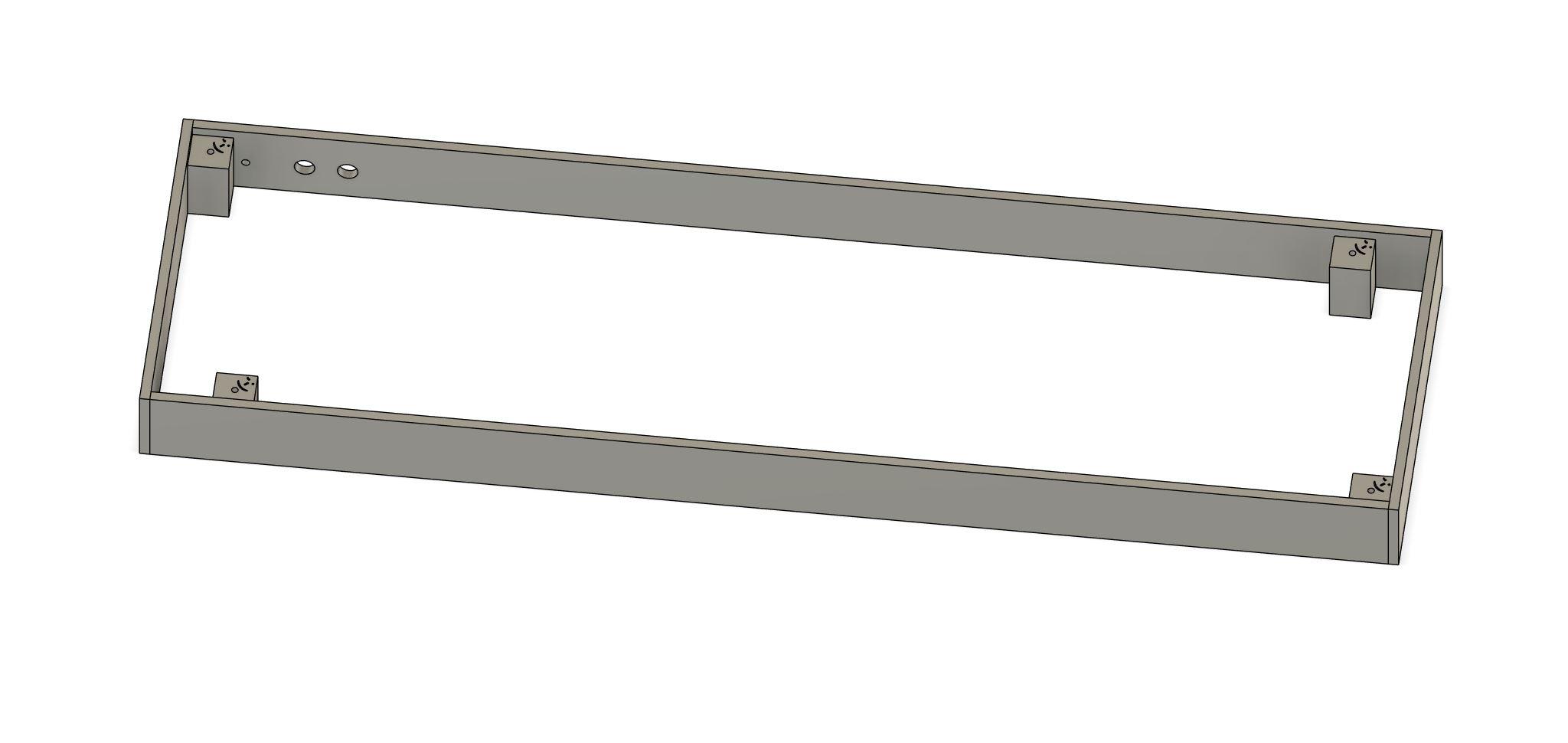
Your wood base should look like Image#3 when all the holes are drilled.
Once all the holes are drilled, unscrew everything and paint the visible face of the wood base in matte black.
2 layers (even 3 if the wood is not black).
The Front Frame


Let's make the removable Front Frame.
Cut 4 pieces of 5mm thick ply wood :
670mm x 65mm x2 (upper and lower walls)
250mm x 65mm x2 (left and right walls)
Place the wood base on a flat surface. Visible face Up.
Place the upper wall in place, aligned with the wood base and glue it to the left wall (NOT to the wood base !)
Place the lower wall in place and glue it to the left wall (NOT to the wood base !)
Place the right wall and glue it to the upper and lower walls (NOT to the wood base !) (see Anim#1)
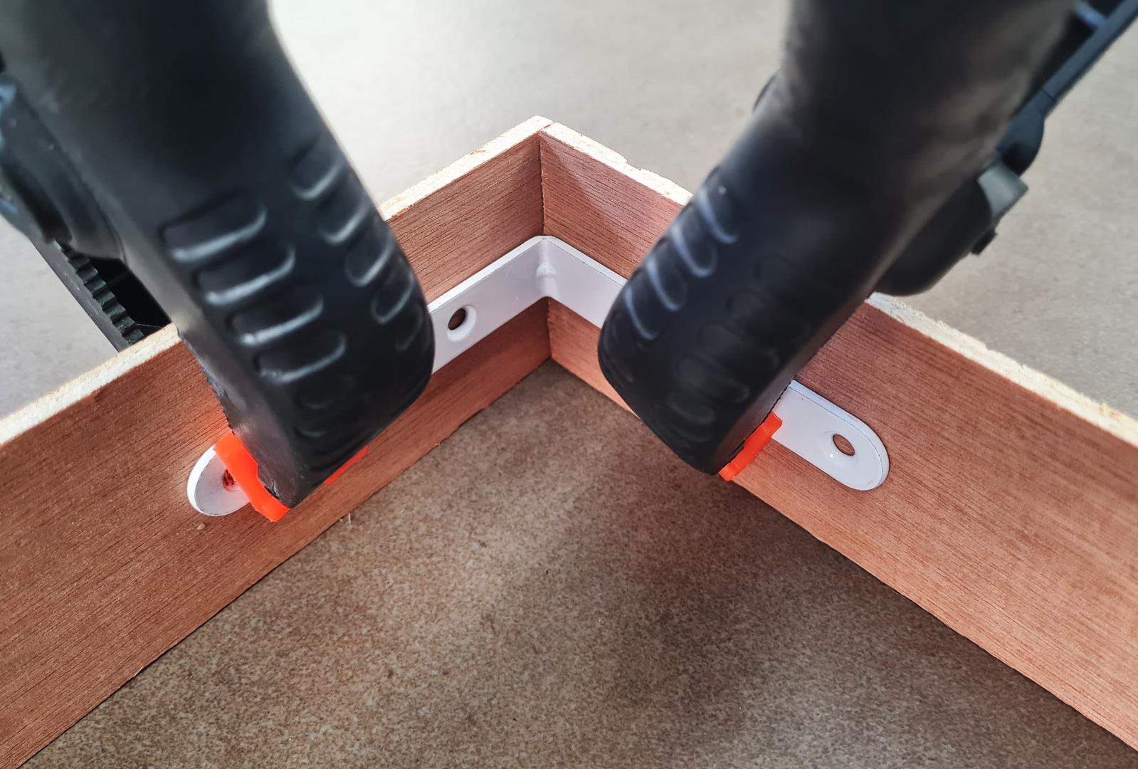
To place correctly the different walls you can help with metal corners and clamps. (Image#1)
Let dry.
Place the 4 PLA Front_Wedges in the 4 corners, in contact with the wood base, smiley face visible and glue them (with Cyano glue) to the front frame (NOT to the wood base !) (Image#2)
Insert a 2mm pencil lead inside the holes of the 4 corner wedges to mark the holes on the wood base.(Image#3)
Drill the 4 corner holes in the wood base at 4mm of diameter.
Paint the entire frame (inside and outside) in matte black.
Now let's make the aluminium frame.
For the Upper and lower corners the outer length is 683mm.
For the Left and Right corners the outer length is 253mm.
You can find help to mark the cut with the PLA 45°degrees tool (see Image#4)
Cut with a Dremel loaded with a metal cutting disc (or the tool you like most)
Before gluing the aluminium corners to the wood frame, check if everything fits together.
If not, use sand paper or the metal cutting disc on the Dremel to adapt correctly the different pieces. This was the hardest phase for me ;-)
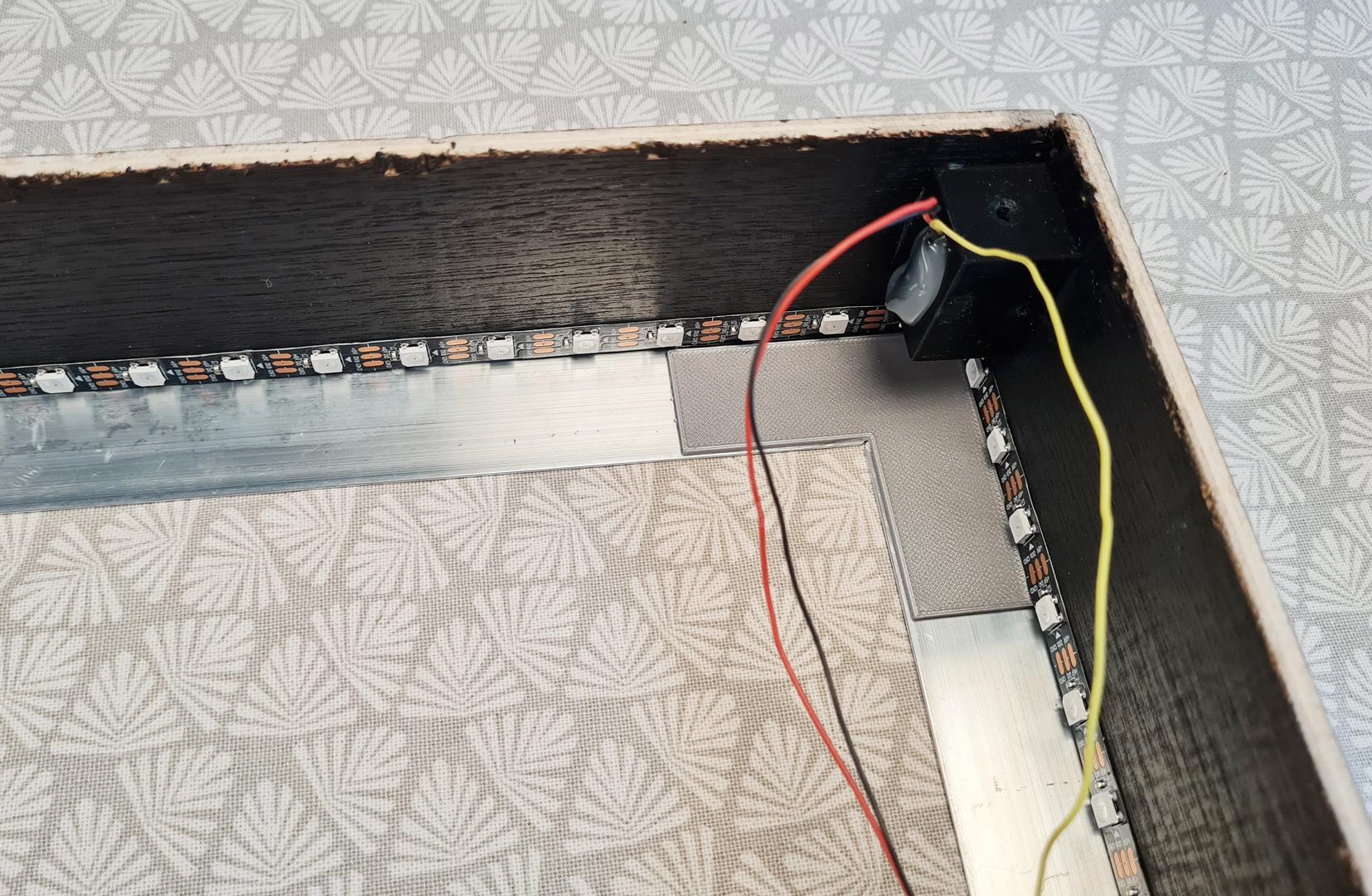
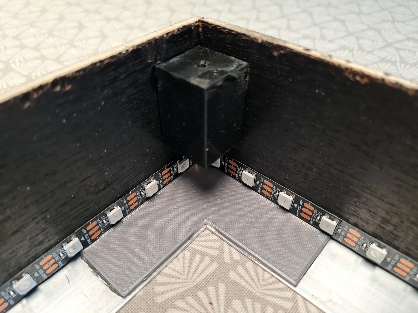
Then glue the 4 aluminium corners to the wood frame and glue the 4 PLA Corners on the inside face of the aluminium frame. (see Anim#2 and Image#5 and #6).
To make the aluminum shiny, I used a metal polish and a microfiber cloth.
Solder 3 wires (around 25/30 cm, 5V, GND, DIn) to the DIn side of the 108 LEDs strip (beware the arrow).
Male Dupont Connectors to the other end of the wires.
Stick the LEDs strip like shown on Images #6 and #7 , First LED in the upper left corner when facing the display. Then Clockwise when facing the display.
Now you have the fully removable Aluminium front frame. Don't screw it to the Wood base for the moment.
The Rear Box


Now we have to lodge all the electronics in a rear box.
Cut the pieces in the 5mm thick plywood :
- 600 mm x 40mm x2 (upper and lower walls)
- 180mm x 40mm x2 (Left and Right walls)
- 610mm x 180mm x1 (Lid)
On a plane surface, place and glue the different pieces as shown in the Image#1
You can help with metal corners and clamps to hold everything orthogonal.(see Image#2)
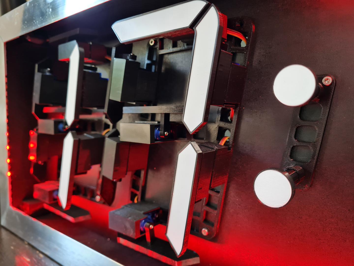
On the upper wall of the Rear box drill 2 holes for the push buttons (check the diameter of your buttons) and one hole for the LED cable (3mm diameter) as shown on Image#3.
Then glue the 4 wedges . Smiley face of the wedge visible. Other side in contact with the surface beneath.
2 of them in the angles and 2 of them slightly moved away from the holes that are in the corners. (see Image#4)
Place the Lid on a plane surface.
Place the rear box on top of the lid (smiley faces of the wedges visibles) and align with it. Then mark the holes on the Lid, through the wedges with a 2mm Pencil lead.
Drill holes in the Cover at 4mm diameter.
We can now glue (wood glue) the rear box at the back of the wood base. 30mm from the top and 30mm from the left. Smiley faces of the wedges NOT VISIBLE. (see Image#5)
Let dry.
The Electronics

Let's add a brain to our clock !
When I first design this panel, I choose an Arduino Nano and a Real-time clock board (DS3231) to get the time, but it was so imprecise (like 1 minute in advance per day !!!) that I decided to change for an ESP32 wifi board and catch the real time (UNIX Time) on Internet via WIFI network.
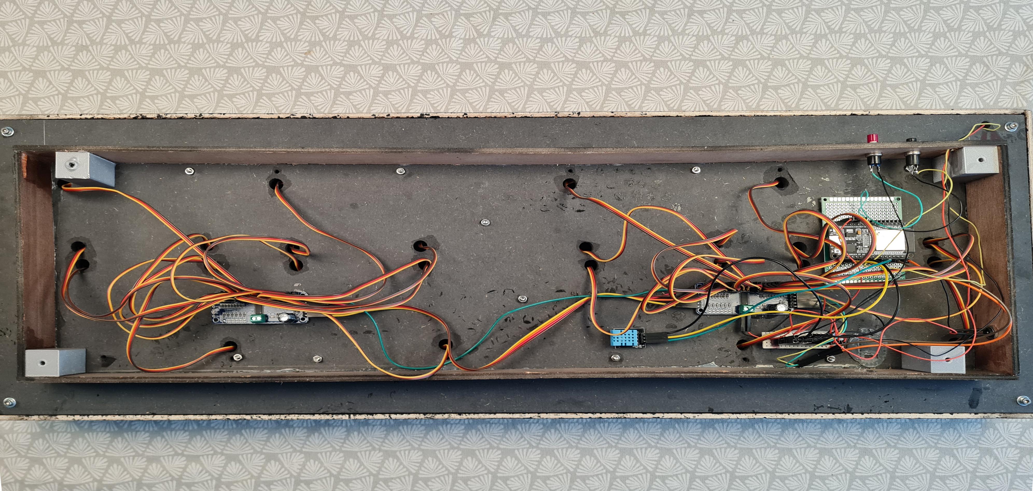
I choose not to solder every component for the versatility of the system.
The Dupont connectors was the solution (for me!). You could choose to solder everything, it's up to you.
I glued all the components with hot glue to the back of the wood base. (see Images #3 and #4)
A small home made PCB helped me to centralize power and ground connections. (Images #1, #3 and #4)
Let's appreciate the cable managment :-)))
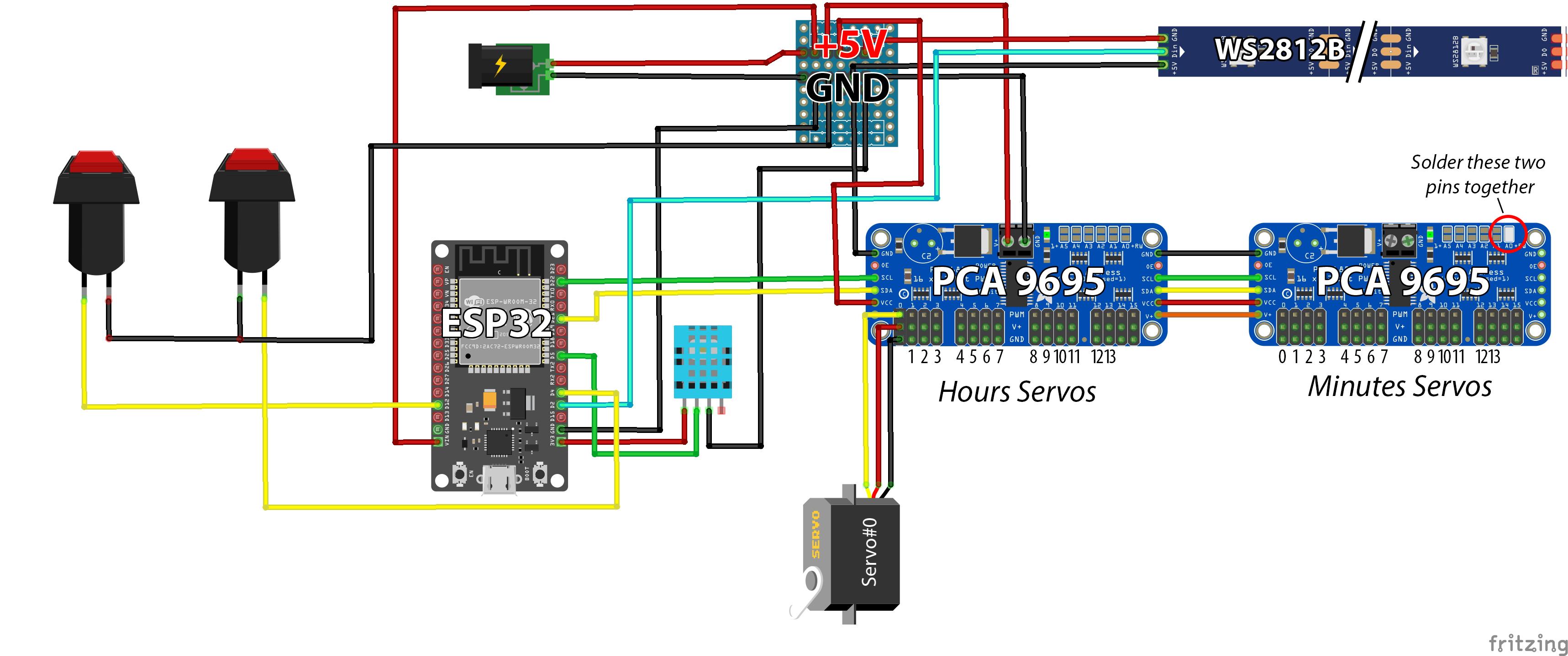
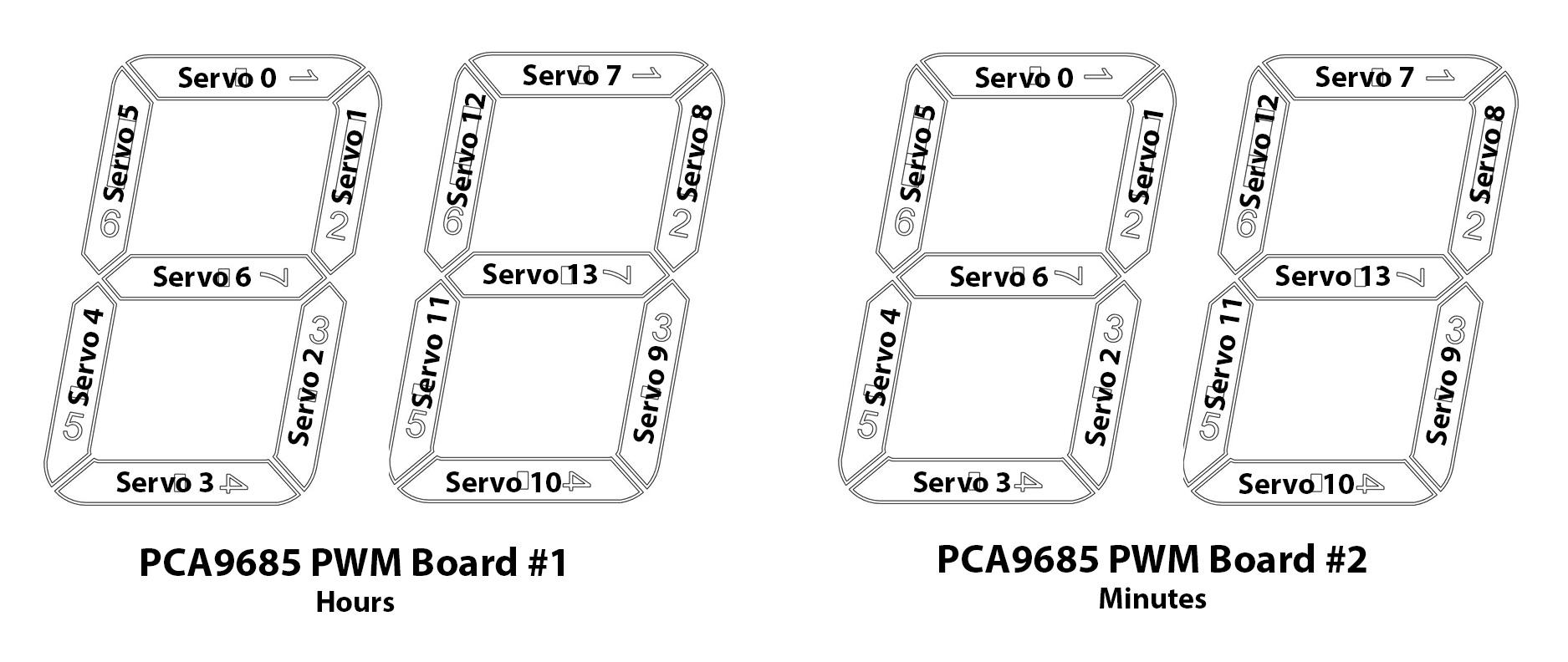
Tin the I2C adress on the Minutes board. (image #1)
Then let's connect everything as shown on the electronic diagram (image #1 and #2).
Mounting the Digit Unit
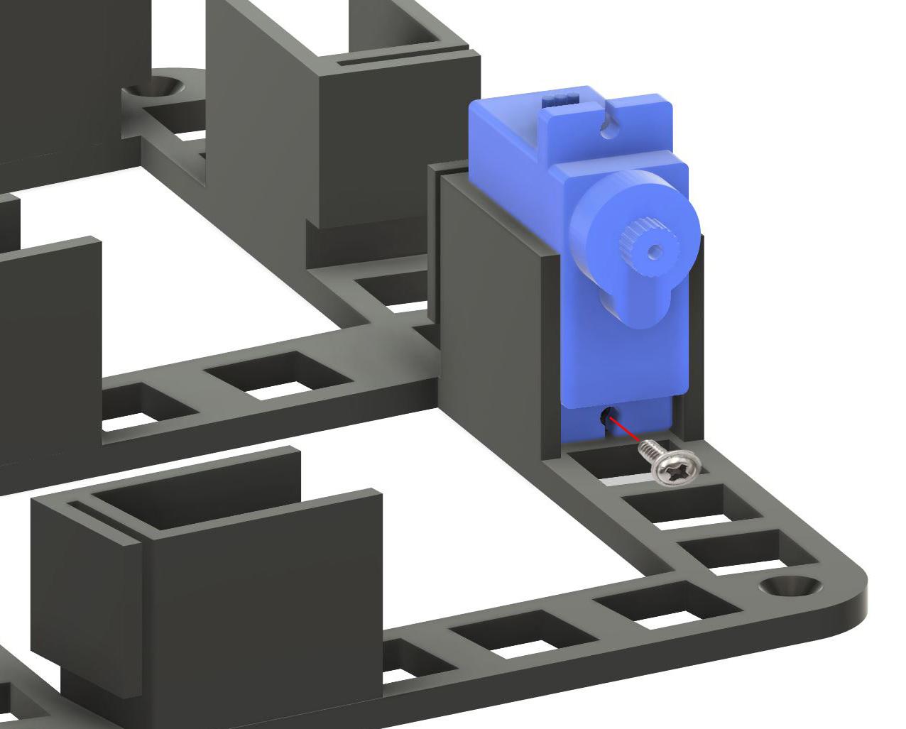

- Insert the 7 servos in place (On the PLA Base) and screw them to the bottom hole of each support. (see image#1).
- Pass the cables inside the small path at the back of the servo.
- Place each PLA Base on the wood base and screw them in place.
- Pass all the servos cables through the 10mm holes of the wood base and connect them to the PCA9695 PWM Boards like shown in image#2.
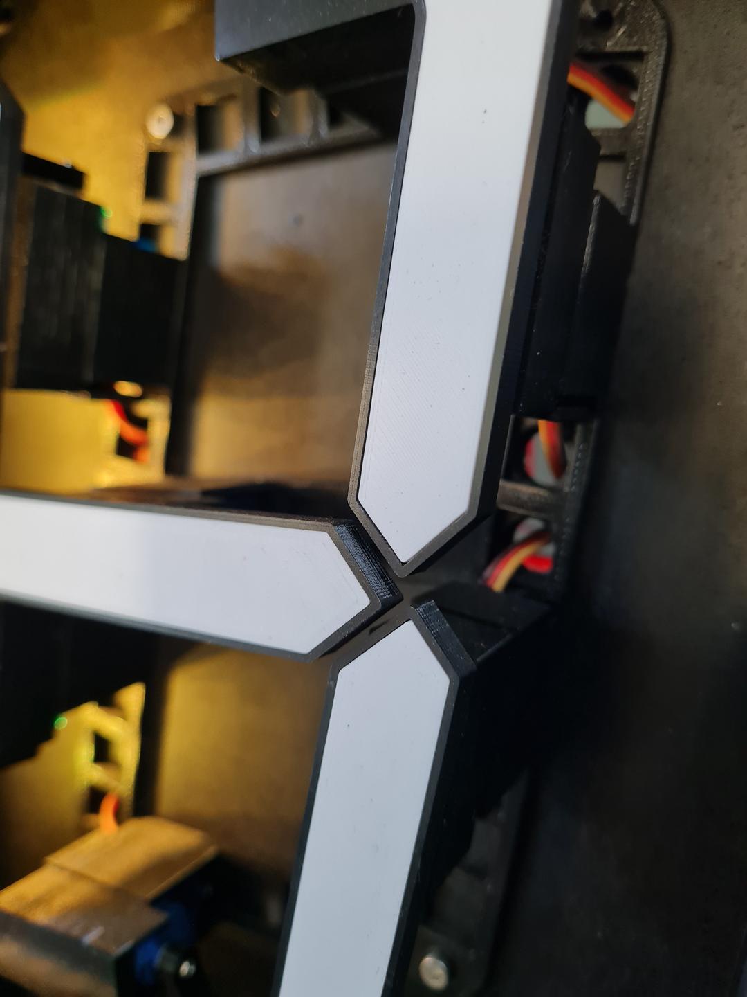
- Insert each arm into their respective segment. Watch the orientation. Easy with the printed numbers ;-)
Tolerance between arms and segments is tight so you normally don't need to glue.
- You can easily differentiate between arms 2 and 6. Arm 2 is longer than arm 6
- Do not place the SegmentsWhite for the moment so you'll be able to read the numbers when placing the arms on the servos.
- REPEAT THIS FOR THE 4 UNITS.
- Insert the 2 Dot_White in the 2 Dots. Insert the 2 Dots in the Dots_base. Glue if necessary.
- DO NOT place the arms on the servos for the moment.
- Let's first calibrate all the servos.
Calibrate the Servos

Before attaching the arms to the servos axes, we must calibrate the servos.
ESP32 connected to the computer. Power ON.
Open the Servos_Calibration.ino file.
You'll have to install this library first >> Adafruit_PWMServoDriver : HERE
Upload the file to the ESP32.
All the servos will move in the ON position of the arms.
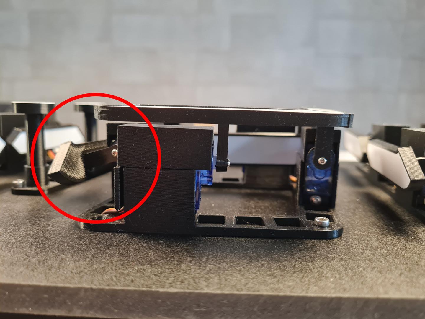
Then place the arms/segments #1 on all digits in upper position on the servo (arm orthogonal to the wood base, segments visible and parallel to the wood base), like shown in image#1.
Screw them in the servo axis.
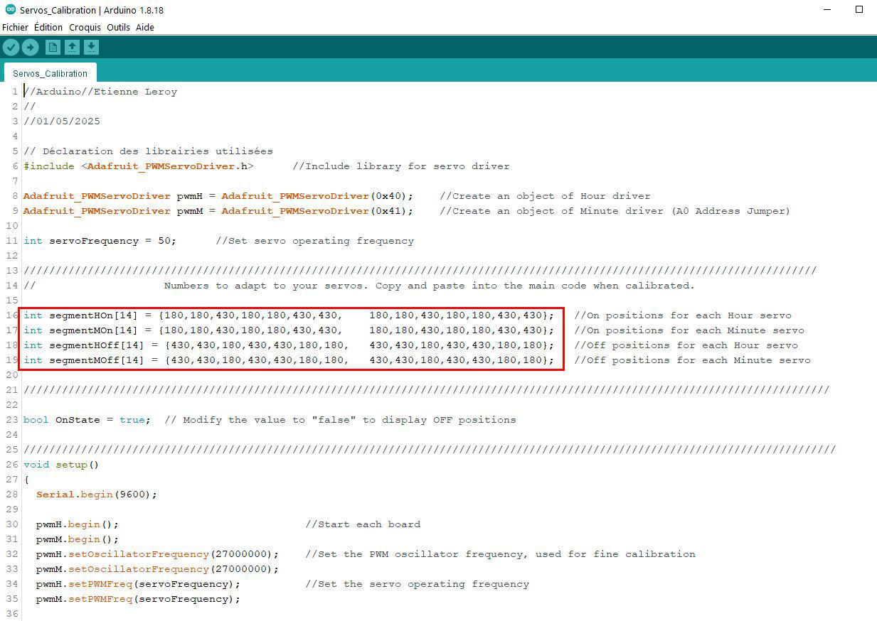
You can slightly adjust the position of the arm modifying the 1st and 8th numbers in lines 16 (segmentHOn) and 17 (segmentMOn) of the code. See Image#2
Try with increments or decrements of 10 to align correctly the segments.
(Line 16 for the hours digits. Line 17 for the minuts digits).
Upload the code again and repeat operation until the segments are in good position.
Repeat these steps for all the arms/segments until all the segments are right in place.
Exemples : To adjust the segments #2, modify the 2nd and 9th numbers in lines 16 and 17 of the code.
To adjust the segments #6, modify the 6th and 13th numbers in lines 16 and 17 of the code.
Etc...
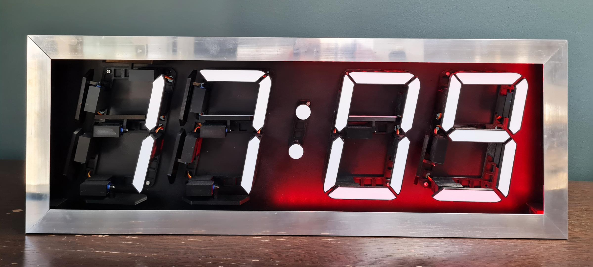
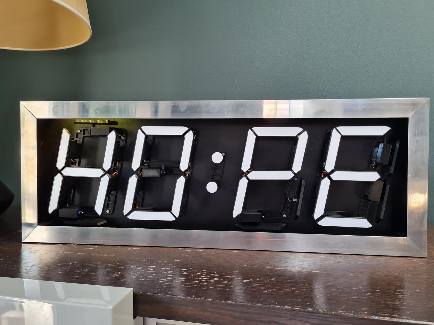
All the arms/segments are now screwed to each servo, in ON position. Displaying 88:88.
You can now place the SegmentWhite_1 to _7 in their respective Segments. Glue if necessary.
Now we have to calibrate the OFF postion of each servo.
Modify the code on line 23 >> bool OnState = false;
And Upload the new code to the ESP32.
All the servos will move in the OFF position of the arms.
It's time to put all the Servo_Covers on the Servomotors.
You can slighly adjust the position of the arms/Segments #1 modifying the 1st and 8th numbers in lines 18 (segmentHOff) and 19(segmentMOff) of the code. (Line 18 for the hours digits. Line 19 for the minuts digits).
See Image#2
Try with increments or decrements of 10 to align correctly the segments.
Upload the code again until the segments are in good position.
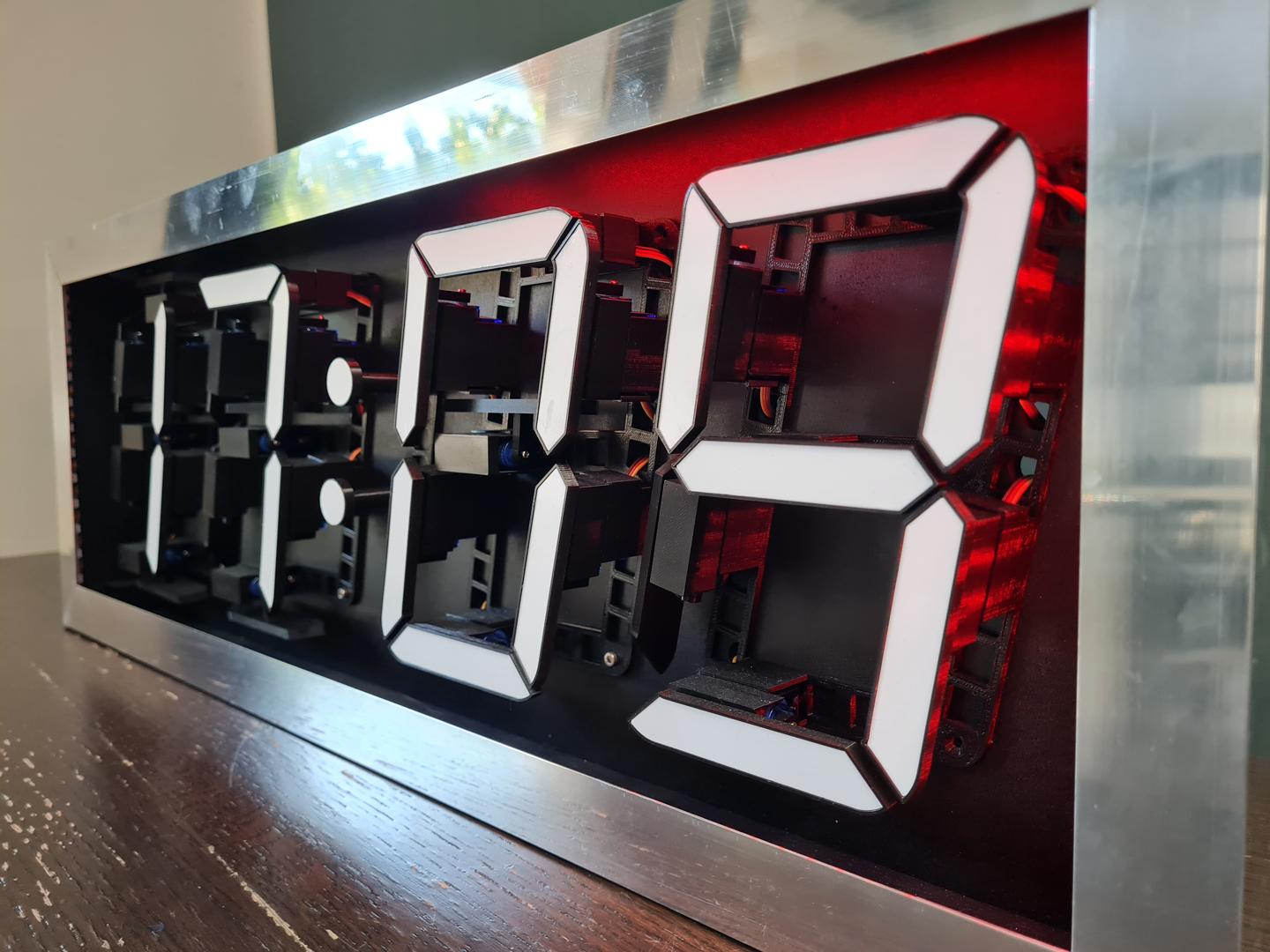
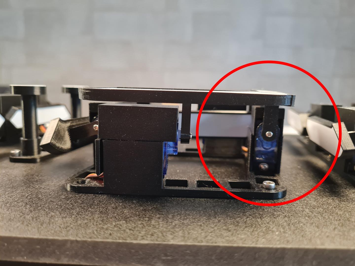
The good OFF position is slightly beyond the Orthogonal position of the arm.
So the white part of the segment will NOT be visible when OFF. (see images#3 and #4)
Repeat these steps for all the arms/segments until all the segments are right in place.
Exemples : To adjust the segments #2, modify the 2nd and 9th numbers in lines 18 and 19 of the code.
To adjust the segments #6, modify the 6th and 13th numbers in lines 18 and 19 of the code.
Etc...
You can switch between ON or OFF positions just by modifying the value of "OnState" Variable to true(ON) or false(OFF).
Don't forget to Save the Servos_Calibration.ino file with the correct values to your computer.
Downloads
Screw the Front Frame
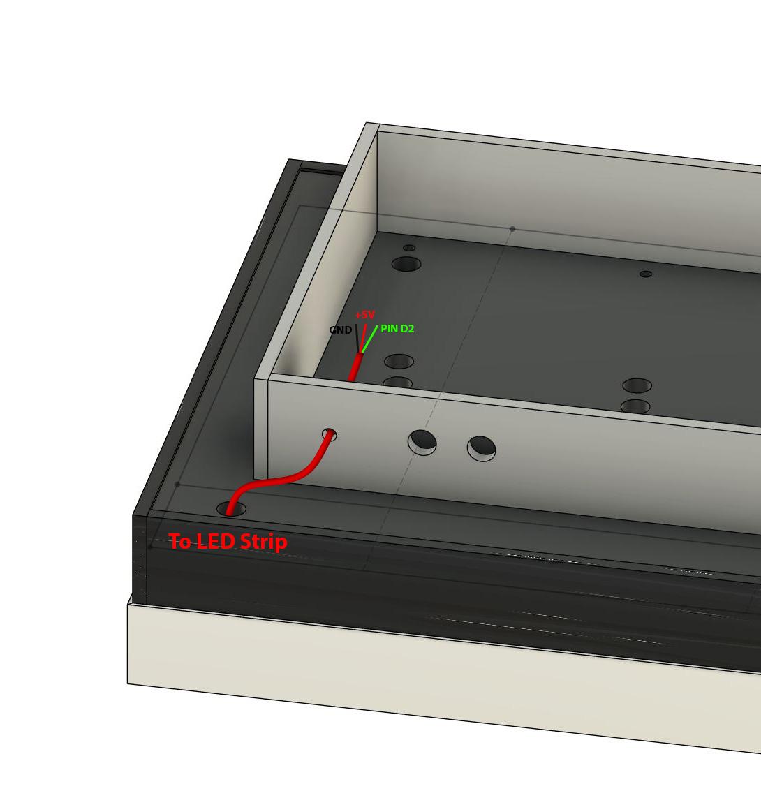
Before installing the front frame, pass the LEDs cables through the wood base and through the rear box.
(see Image#1)
Now, screw the front frame to the wood base, using M3 screws, to the bolts that are already in the wedges.
Upload the Final Code


First you'll have to install several libraries for the code to run :
- WIFI : HERE
- EasyNTPClient : HERE
- TimeZone : HERE
- FastLED : HERE
- DHT (for temperature and humidity sensor) : HERE
- OneButton : HERE
Open Servos_Calibration.ino file.
Open 7_Segments_Wifi_Clock.ino file.
-ServoMotors Parameters :
Copy the 16,17,18 and 19 lines of the Servos_Calibration.ino file. Close Servos_Calibration.ino.
Paste them to replace 42,43,44 and 45 lines in the 7_Segments_Wifi_Clock.ino file. (image#1)
-WIFI Parameters :
On Lines 491 and 492, you'll have to fill with your WIFI network name and password. (image#2)
-Time Zone Parameters :
On Lines 33 and 34, you'll have to define your Time Zone. (image#3)
The code is grabbing the UNIX time on internet.
UNIX time is the number of seconds elapsed since 1st of January 1970 in UTC (Coordinated Universal Time).
The parameters to change are the parameters between the brackets in lines 33 and 34.
What does it mean ?
In France we apply summer and winter time. (see exemple#1)
Summer time is beggining the last sunday of march at 2AM and it results in 120 minutes in addition of the UTC time >>> {"RHEE", Last, Sun, Mar, 2, 120}
Winter time is applying the last sunday of october at 3AM and it results in 60 minutes in addition of the UTC time >>> {"RHHE", Last, Sun, Oct, 3, 60}
If your country do not apply these summer and winter time changes put the same number just before the closing bracket (see exemple #2).
Exemples :
1/ You live In NYC (USA) :
Summer time begin the 2nd sunday of march at 2AM (UTC time - 240 minutes = 4 Hours) and ends the 1st sunday of november at 2AM (UTC time - 300 minutes = 5Hours)
So the code will be :
line 33 {"RHEE", second, Sun, Mar, 2, -240};
line 34 {"RHHE", first, Sun, nov, 2, -300};
2/ You live In New Dehli (India) :
No changes between summer and winter
Change only the last number for 330 ( UTC + 5H30 or UTC + 330Min) on both lines 33 and 34.
>>> For more precisions you could check the library github HERE
-Words mode Parameters :
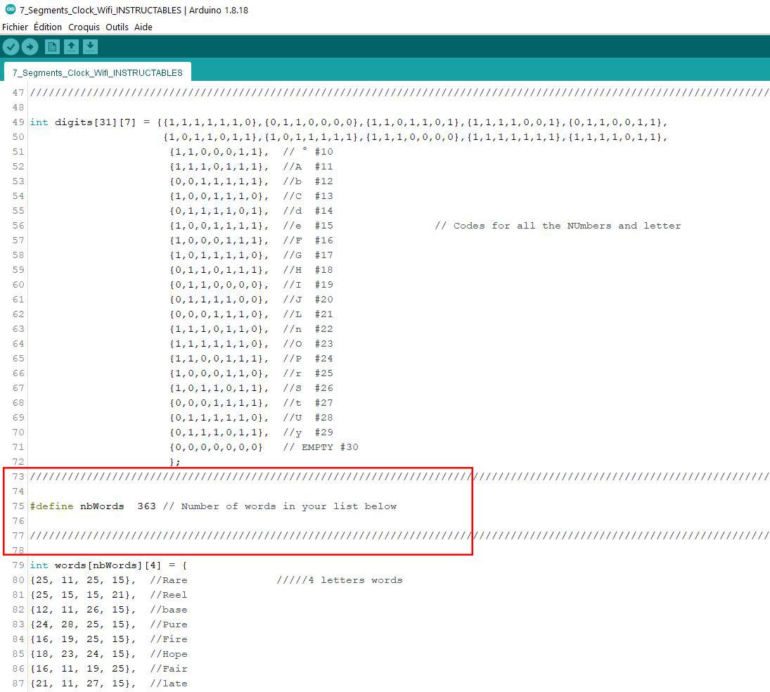
You can, of course, create your own list of words, modifying the variable "words[nbWords][4] = ", line 79 and after.
This Clock is NOT able to display the following letters : K, M, Q, V, W, X and Z.
Each word is coded with 4 numbers corresponding to the 4 letters of the word according to the following :
A=11, B=12, C=13, D=14, E=15, F=16, G=17, H=18, I=19, J=20, L=21, N=22, O=23, P=24, R=25, S=26, T=27, U=28 and Y=29.
AI (ChatGPT or equivalent) may be your friend to create a list of existing words (without the forbidden letters!) and code them into this pattern
{1st letter, 2nd letter, 3rd letter, 4th letter}, // Word
Don't forget to count the exact number of words that are in your list and change the value of the variable "nbWords" at line 75 of the code. (image#4)
Save 7_Segments_Wifi_Clock.ino file on your computer.
Upload it to the ESP 32 and you're good to go !
Screw the cover of the rear box with M3 screws.
Credits : My final code is a mix of different codes found on the internet and adapted to this project.
Check them :
Moving the segments to display time or whatever : There
Grabbing time on the internet : Here
Downloads
Enjoy !
)


How it works :
One short press on the first button to change mode.
Default mode is Mode 1.
Mode 1 : Clock Mode (image#1)
Display actual time in your Time Zone. Refreshing every minute. Refreshing Summer and Winter times if coded.
Red LED lights ON, one by one, all the way around, like seconds on a analogic clock. LEDs OFF when minute changes. To change the color, Change the value of "LedColorTime", line 459 of the code.
Mode 2: Words displaying (image#2)
Display a random word, chosen in the list.
Random LED color. LED lights ON one by one, from the upper left corner, all the way around, according to the selected refreshing interval. Then LEDs lights OFF, one by one, from de upper left corner, all the way around, according to the refreshing interval selected.
And repeat...
Mode 3 : Temperature displaying (image#3)
Display the actual temperature of the room. One decimal.
LEDs lights ON changing color from red to red across the color wheel, according to the refreshing interval selected.
When you're in mode 2(Words) or 3(Temperature), a long press on the first button will lead to the Duration Menu.
This will allow you to change the intervals between refreshings (both words and temperature).
Default value is 5 minutes.
Short press on the 2nd button changes the refresh interval. Available values are 1, 5, 10, 15, 30, 45, 60 minutes and so on.
To store your value and quit the duration menu : Long press on the 1st button.
Short press on the 2nd button when you're NOT in the duration menu will lead to refresh the word or the temperature.
It's now time to enjoy you're brand new 7 segments display !
Upgrades
Some ideas I had to upgrade the project :
- Adding a ON/OFF switch instead of Plugging/unplugging the power line. (level easy)
- Adding a Photoresistor to adapt the LED brightness according to ambient lightness.
- Displaying Humidity in your room.
- All kinds of LED patterns, playing with time.
- Coding a timer.
- Designing a mechanism to make the 2 dots invisible when words displaying.
- Buying quiet microservos. It is quite noisy when updating display with these ones.
- Up to your imagination... ;-)
Thank you for reading these lines and sorry if there are some errors in my english.