One Button Based 5-20V USB-C PD Voltage Selector
by sainisagar7294 in Circuits > USB
129 Views, 2 Favorites, 0 Comments
One Button Based 5-20V USB-C PD Voltage Selector
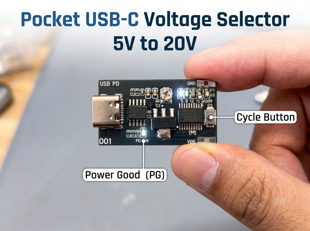
USB-C PD Selects the Voltage from 5V to 20V at the Press of a Button with CH224K + CH32V003 RISC-V
Supplies
Components Required
Here is the complete list of components I used for this project:
- USB Type‑C Connector
- CH224K
- CH32V003F4P6
- LM317DCYR
- LEDs
- 1 kΩ Resistors
- 10 kΩ Resistors
- Voltage Divider Resistors
- 100 nF Capacitors
- 1 µF Capacitors
- 16 pF Capacitor
- Push Button Switch
- Screw Terminal Block
- Custom PCB from JLCPCB
STORY:
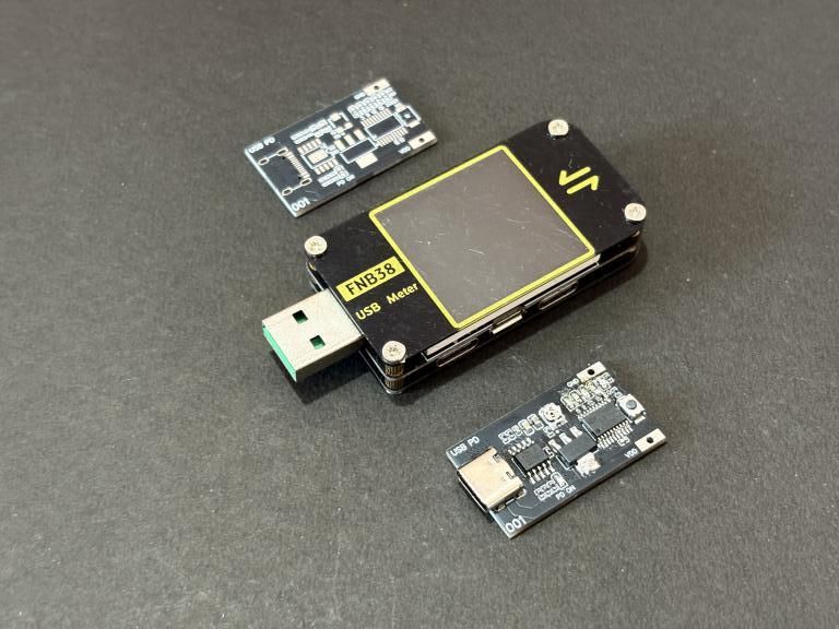
In the past, I have worked on Power Delivering (PD) ICs. They are perfect for getting instant voltage from a GaN charger. I made a simple, standalone board that lets me select different PD voltages by charging the register settings. But why not keep it more usable with a single-button setup and a 10-cent microcontroller? No OLED displays, no rotary encoders, no over-engineering, just a simple toggle button with a few LEDs. That is exactly what I built in this project using the CH224K USB PD sink controller and the CH32V003F4P6, both made on WCH hardware.
The idea is straightforward. You plug in a USB-C PD charger, press the button to cycle through 5V, 9V, 12V, 15V, and 20V, and the corresponding LED lights up to tell you which voltage is currently active. I have designed the circuit in EasyEDA and manufactured the PCB with JLCPCB to realize this idea. In this session, I will share the code and hardware files so you can easily build your own. Let’s get started.
What Is USB Power Delivery?
Traditional USB ports give you 5V, and that is it. USB PD is a protocol that allows a charger and a device to negotiate higher voltages and currents over the USB-C cable. A typical USB PD charger can deliver 5V, 9V, 12V, 15V, and 20V, with a maximum power of 100W. This came into play when fast charging became popular in mobile phones: it is easy to charge at a higher voltage while fast charging because the mobile's internal circuits buck down and charge the battery at a higher current locally.
This negotiation happens over the CC (Configuration Channel) lines on the USB-C connector. The sink device tells the source what voltage it wants, and the source either agrees or offers the closest available option. This makes PD sink boards incredibly useful for makers and electronics hobbyists. Here, I have a dedicated chip for all this: CH224K. Based on three configuration pins (CFG1, CFG2, CFG3), it automatically negotiates the voltage with the PD source. You can use fixed resistor values, or you can drive the CFG pins with a microcontroller for dynamic voltage selection, which is exactly what I am doing here.
Key features of the CH224K:
- Supports USB PD 2.0 and 3.0 protocols
- Selectable output voltages: 5V, 9V, 12V, 15V, and 20V
- Three configuration pins (CFG1, CFG2, CFG3) for voltage selection
- Power Good (PG) output for voltage-ready indication
- Built-in CC pull-down resistors for USB-C detection
- Available in a compact SOP-10 package
- Operating supply voltage: 3.3V to 5.5V
Choosing a Microcontroller for Action
The main problem is the device's cost; I cannot pick a controller that exceeds the device's cost beyond the actual functionality cost. CH32V003F4P6 is WCH's ultra-low-cost $0.10 MCU. Despite the price, it is surprisingly capable for simple control tasks like this project.
Key specifications of the CH32V003F4P6:
- Core: QingKe 32-bit RISC-V2A, up to 48 MHz
- Flash: 16 KB
- SRAM: 2 KB
- Package: TSSOP-20 (20 pins)
- GPIO: 18 I/O pins
- Peripherals: USART, I2C, SPI, ADC, timers
- Operating voltage: 3.3V to 5V
- Cost: approximately $0.10
For this project, I am using 9 GPIO pins total. 3 for driving the CH224K configuration pins, 5 for the indicator LEDs, and 1 for reading the push button.
Circuit Diagram
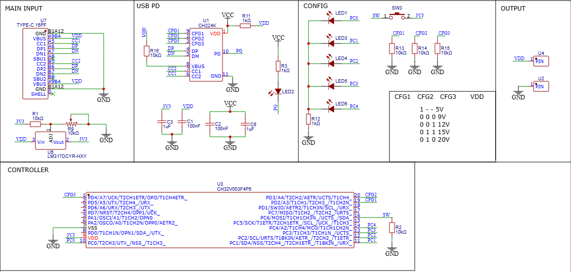
The USB Type-C connector is a standard 16-pin one. The VBUS pins carry the PD voltage from the charger, and the CC1/CC2 lines connect directly to the CH224K for PD communication. The three configuration pins CFG1, CFG2, and CFG3 are connected to the MCU's PD2, PD3, and PD4 pins, respectively.
There is a 10K pull-down resistor on the VDD line and decoupling capacitors to provide clean power to the IC. The PG (Power Good) pin of the CH224K directly drives LED2 through a 1K resistor. This LED lights up at the corresponding voltage at the output. I chose the LM317 because it can handle a wide input voltage range, which is important here since the VDD rail voltage varies with the selected PD voltage. Whether you have 5V or 20V on the input, the LM317 keeps the MCU supply at a stable 3.3V.
Note: Solder the MCU after configuring the LM317 potentiometer to 3.3V; otherwise, you will burn the MCU.
The firmware uses this exact table to set the correct voltage on each button press:
CFG1,2,3 and Voltage
1 - - 5V
0 0 0 9V
0 0 1 12V
0 1 1 15V
0 1 0 20V
PCB Design
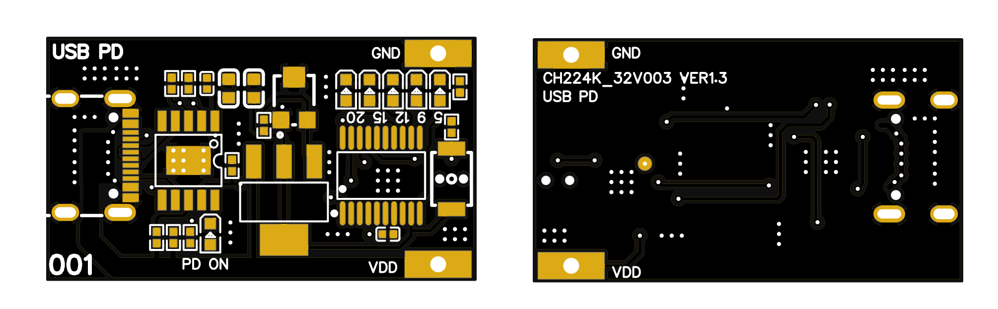
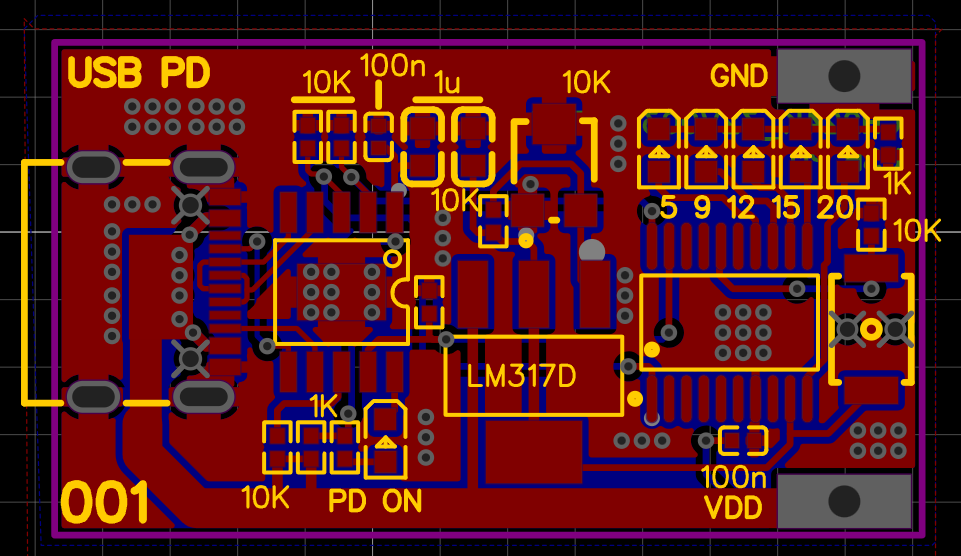
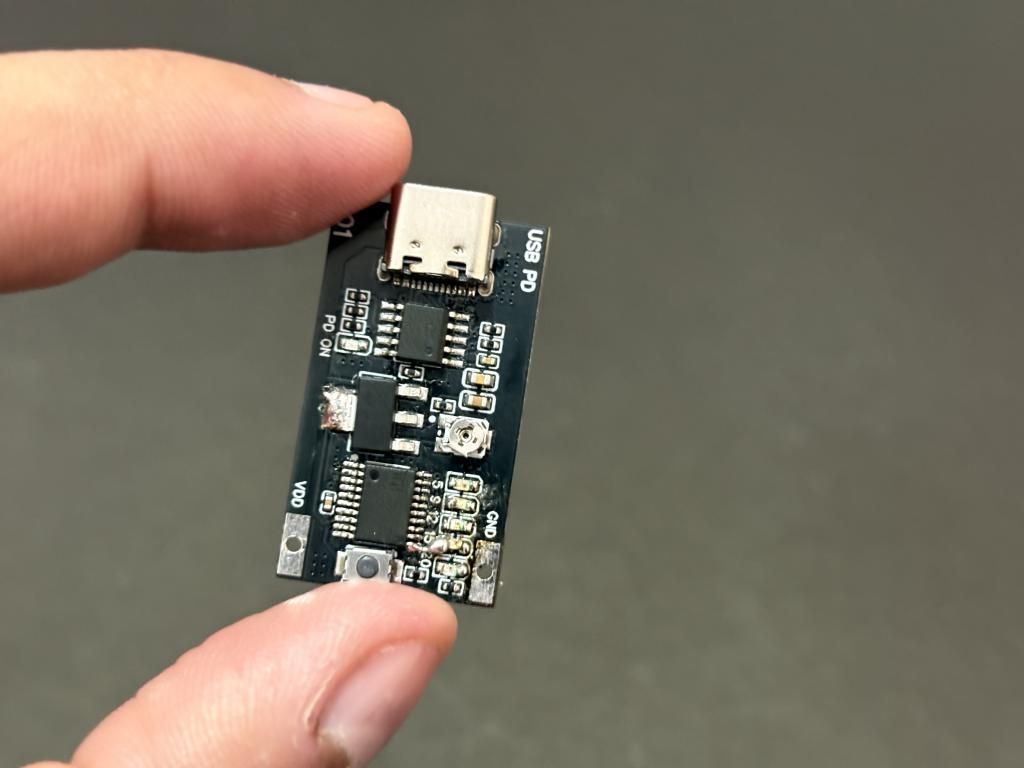
I designed the PCB in EasyEDA as a compact two-layer board. The layout is organized with the USB-C connector on the left, the CH224K and supporting components in the center, and the indicator LEDs, button, and output terminal on the right. The board has silkscreen labels for the voltage levels 5, 9, 12, 15, 20 next to each indicator LED.
The Power Good LED and the "PD ON" label are placed near the CH224K section. For the power traces carrying VBUS current, I used wider traces to handle the higher currents that USB PD can deliver (up to 5A at 20V, that is 100W). The LM317 regulator is positioned centrally with adequate copper area for heat dissipation. I get 5 of them fabricated from JLCPCB because they offer the best price-to-performance. I never had a problem fabricating the PCBs from JLC. Get your fabrication files(Gerber/BOM/CPL) from here and get started.
Firmware Explanation
The firmware for the CH32V003 is written in C using WCH's MounRiver Studio IDE and their standard peripheral library. The code is clean and minimal. It does exactly three things: read the button, update the CH224K configuration pins, and light the correct LED. Let me walk you through each part.
GPIO Configuration: The `GPIO_Config()` function configures all required pins. First, we enable the peripheral clocks for Port C and Port D:
Then we configure PC0 through PC4 as push-pull outputs for the LEDs, PC5 as a floating input for the button (since we have an external 10 kohm pull-down resistor via R2), and PD2-PD4 as push-pull outputs for the CH224K CFG pins. At the end, we set all LED pins HIGH to turn them off (remember, active-low configuration).
Lookup Tables for Configuration: This is the clever part. Instead of using a big switch-case block, I created three lookup tables that map the mode index (0 through 4) directly to the CFG pin states:
Mode 0 is 5V (CFG1=1, don't care about CFG2/CFG3), mode 1 is 9V (all zeros), mode 2 is 12V (CFG3=1), mode 3 is 15V (CFG2=1 and CFG3=1), and mode 4 is 20V (CFG2=1, CFG3=0). The `led_table` maps each mode to its corresponding LED pin. This approach is much cleaner than a switch-case and makes it trivial to add or reorder modes.
Setting the CFG Pins: The `setCFG()` function takes three arguments (one for each CFG pin) and drives the corresponding GPIO pins HIGH or LOW:
This is straightforward GPIO manipulation using WCH's peripheral library functions. `GPIO_SetBits` drives the pin HIGH, and `GPIO_ResetBits` drives it LOW.
Applying the Current Mode: The `applyMode()` function ties everything together. It first turns off all LEDs by setting their pins HIGH, then calls `setCFG()` with the values from the lookup tables for the current mode index, and finally turns on the correct LED by pulling its pin LOW:
This function is called both at boot (to set the initial 5V mode) and whenever the button is pressed.
Button Reading with Debounce: The `readButton()` function handles the push button with rising-edge detection and debouncing:
Here is how it works. The function reads the current button state and compares it with the previous state. If the button just went from LOW to HIGH (a rising edge), we wait 20 milliseconds for debounce, then read the button again. If it is still HIGH after the debounce delay, we know it is a genuine press. The mode index increments and wraps back to 0 after reaching 4, cycling through 5V, 9V, 12V, 15V, and 20V in order.
Main Loop: The `main()` function is simple. It initializes the system clock, delay timer, and GPIO pins, then sets the default mode to 5V (mode index 0) and enters an infinite loop that continuously polls the button:
I deliberately chose 5V as the default boot voltage because it is the safest. Every USB PD charger supports 5V, and it will not damage any connected device. You can then press the button to step up to higher voltages as needed.
Power Good LED
One detail I really like about this design is the Power Good LED (LED2). This LED is not controlled by the microcontroller at all. It is directly connected to the CH224K's PG (Power Good) output pin via a 1K resistor (R11).
When the CH224K successfully negotiates the requested voltage with the PD, the PG pin goes HIGH, and LED2 lights up. If the negotiation fails, the PG pin stays LOW, and LED2 remains off. This gives you an independent, hardware-level confirmation that the output voltage is correct and stable. This is especially useful during development and debugging. If your voltage indicator LED shows 20V but the Power Good LED is off, you immediately know the charger could not deliver the requested voltage.
Testing and Working:
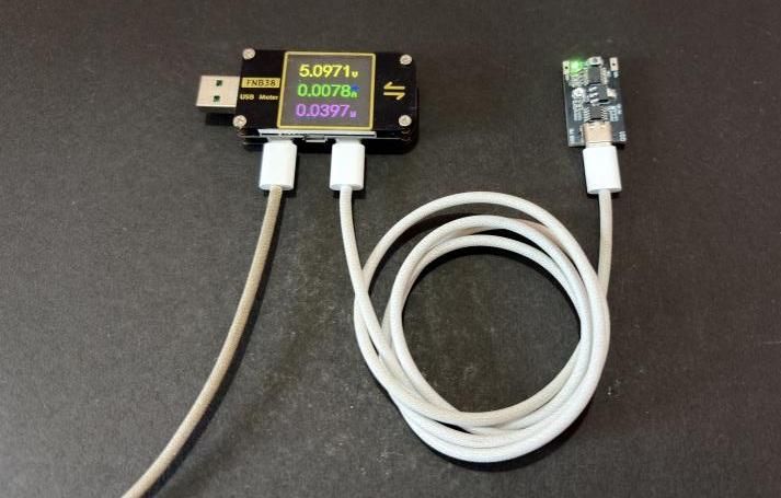
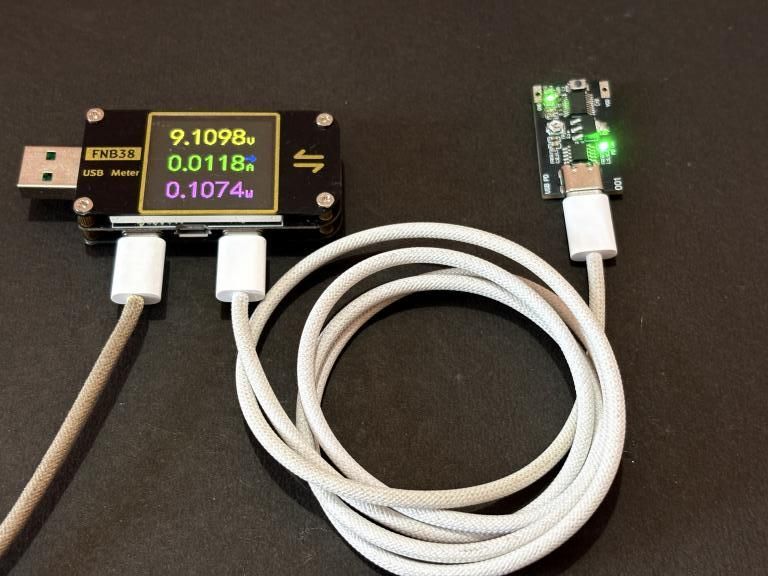
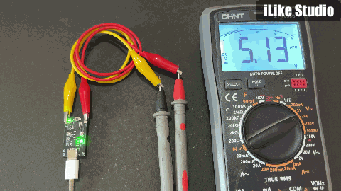
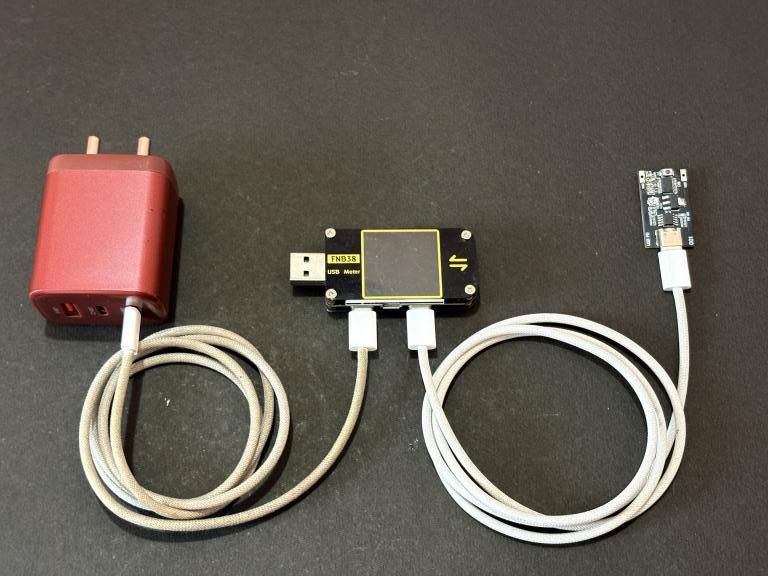
After assembling one of them, I turned it ON! Using a USB meter in series with the charger. This will help to monitor the current and provide overcurrent protection. So if anything goes wrong, the circuit will automatically power down.
Image 1:
Image 2:
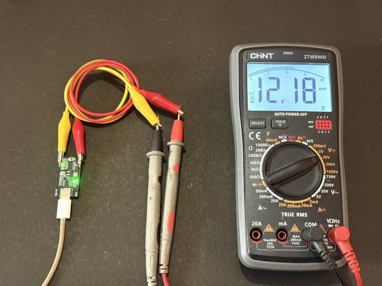
After clearly getting it worked and measuring the idle current, I switched to the charger directly.
Image 3:
Then connected a multimeter in voltage mode, and here are the results.
Outro
This USB PD Voltage Selector project combines two excellent WCH chips. With a single button press, you can cycle through 5V, 9V, 12V, 15V, and 20V, with clear LED indication of the selected voltage and hardware-driven Power Good confirmation. The total cost of this board is remarkably low, thanks to the CH224K and CH32V003 being among the most affordable chips in their respective categories. The firmware is simple, open-source, and easy to modify if you want to add features like EEPROM-based last-mode memory or a long-press to jump directly to a specific voltage. The hardware is minimal, and all the components are easy to source. This project helps you build your own USB PD voltage selector. If you have any questions, suggestions, or ideas for improvements, please comment below. Happy building!