Original Game Cabinet Fusion 360 Creation Guide
by 166088 in Design > Digital Graphics
729 Views, 3 Favorites, 0 Comments
Original Game Cabinet Fusion 360 Creation Guide

I made an original Donkey Kong game cabinet for the Arcade student design challenge.
Supplies
All you will need to make this project is a Fusion 360 account and a 3D printer(optional, I used a
Forming the Base Body


To start I used the Create Cube feature with a width of 75 millimeters, a length of 75 millimeters, and a height of 200 Millimeters. This will act as the body of the game cabinet that we will edit throughout.
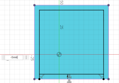
Then to create the curved edge on the top of the game cabinet create a sketch on the top face of your cube and use the project feature to create the outline of the top face on your sketch so you can use the offset line tool to offset the projected square by -5mm to create a smaller square on the top, then to finish the sketch use the create line tool to draw lines from the 2 bottom corners of the square to the base of the original square to section off the front part of the offset outline you created as seen in the image above
Once you have the sketch finished then extrude the square ring you created between the offset and original edge of the top face by 10mm with the join feature selected.
Making Control Board


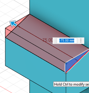
The base control board consists of 2 extrudes the first is going to be a 40mm by 75mm rectangle positioned at the midpoint of the front face of the game cabinet. Then extrude the rectangle by 30mm using the join command.
To then create the slanted part of the control face make a sketch on the right side of the cabinet and from the left side corner of the control face extrusion draw a triangle going 10mm down and 30mm right towards the joint where the control face meets the primary body. then extrude this triangle by -75mm using the cut feature.
Making the Side Walls


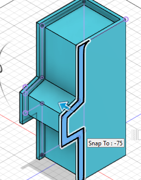

To create the side walls first create a sketch on the right side of the game cabinet and create a line from the top side 10mm down the right face before making an offset line of the right side of the game cabinet and that top line. Then go create a sketch on the left side and project the offset lines from the other side onto the left face, you will need to draw lines from the offset edges to the actual body of the game cabinet so that you can extrude it as a closed shape. on both sides, as separate extrudes, take both sketches and take them -5mm inwards toward the control panel as shown in the image above.
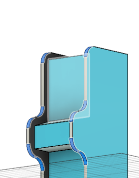
Lastly, fillet the 10 lines shown above by 15mm, they are the top corner line on both sides, the 4 corners from the offset of the control panel, and the 4 lines, 2 of each side, where the offset of the control panel meet the main body of the game cabinet. you will also see I start adding color from here on, I made a Donkey Kong game cabinet so I made the inside of the side walls black and their forward facing edge white but you can do whatever colors you want.
Making the Screen
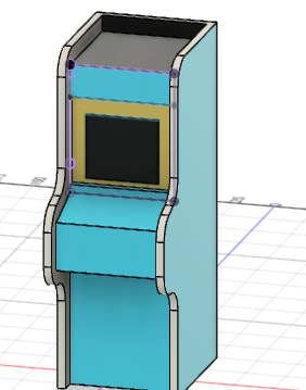

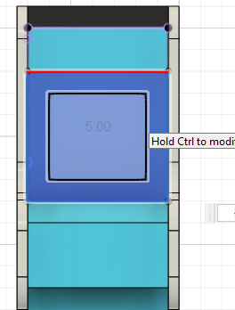

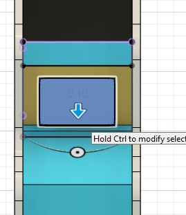
To start, sketch on the front side of the game cabinet make a rectangle from the inside edges of the side walls (65mm), and have it go to the bottom right corner where the control console meets the base of the top part of the forward face (60mm). then offset the rectangle by 10mm.
Then take both the offset rectangle and the offset gap and extrude them by -5mm with the cut function, after make sure to find the gap at the bottom created and extrude it up by 5mm using the join function. Then project the offset rectangle on the screen face before extruding it by 0.1mm so that it is a separate face so it can be colored differently.
Making the Joystick and Buttons


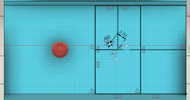

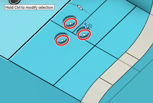


The joystick is created by sketching 2 lines across the midsections of the control board using the midpoint constraint to find the center point of the control board. Using this center point make a center point circle with a diameter of 3mm 12.5mm to the left of the center point along the horizontal midline. Then extrude the circle by 5mm before, using the sphere tool to make a sphere with a diameter of 6mm centered on the top face of the extruded handle.
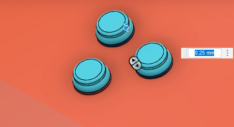
Next, make another sketch on the control board. Start by making a midpoint line cutting the face in half vertically. Using the 2-point square feature to make the half of the face a separate shape and then using the midpoint constraint cut that square into 4ths before cutting the top left quadrant in half lengthwise. Using that point make a circle centered on that point using construction lines with a diameter of 7. Then turn off the construction lines before making a circle centered on a point on the construction line circle with a diameter of 3.5mm and then a second circle with a diameter of 3mm. Then circular pattern in both circles around the center of the construction line circle so that both circles are patterned so there are 3 copies of each.
Extrude the outside circles by 1mm before filleting their outer edge by 1mm to make the button guard. To make the button extrude the inside circles by 1.5mm before filleting them by 0.25mm.
Making the Coin Slot
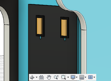
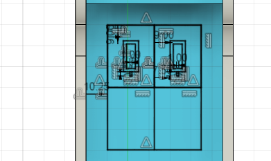
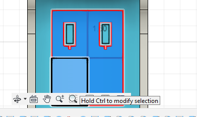


To start once again create a sketch but this time on the bottom section of the front face. Take the rectangular section of the bottom front face and offset it by -10.25mm and then use the midpoint constraint to cut the offset rectangle into quadrants before offsetting the top 2 quadrants by 7.5mm and 9mm to create 4 new rectangles. and then at the midpoint of both 7.5 offset rectangles create a 1mm by 2mm rectangle.
(For all these extrudes assume they use the join feature unless otherwise stated) For the extrudes, start by extruding the quadrants that are not sectioned off in the top 2 by 1.5mm, then extrude the small rectangles at the bottom by -20mm using the cut function, next extrude the outer offset rectangle by 2mm, and lastly extrude the inner rectangle by 3mm. You do see the last extrude one of them is invisible on my side and this is because in the appearance menu, I colored these faces with transparent plastic so that they look like arcade start buttons.
Adding in the Fan (opptional)


To start on the Fan sketch the front face of the control board and make a 16.5mm line that is at the horizontal midpoint of the face. Where that line ends create a circle with a diameter of 22.361mm made of construction lines. Then on the left side made 4 and a half ellipses before mirroring them at the half line to make sure the fan is even. I free-handed the measurements of these based just on what I thought looked good so play around with these measurements and use whatever you feel looks best. Then extrude the drawn ellipses by -20mm using the cut function, if you think this is to much then change the measurements because these add-ons are purely optional and you can do what ever you want.