Oscillating Desk Fan From CPU Cooler
by RichardHuberjohn in Circuits > Electronics
405 Views, 4 Favorites, 0 Comments
Oscillating Desk Fan From CPU Cooler
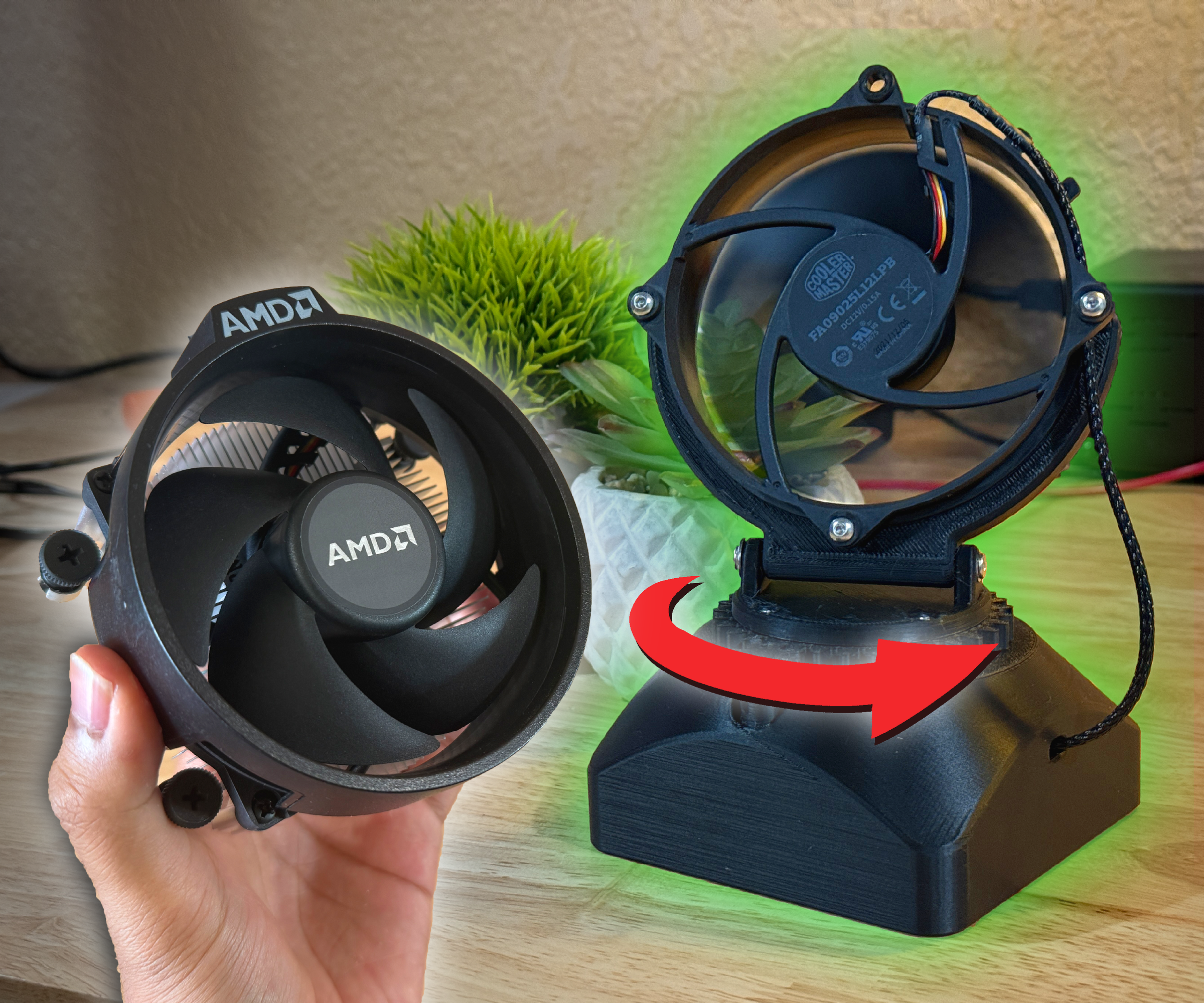
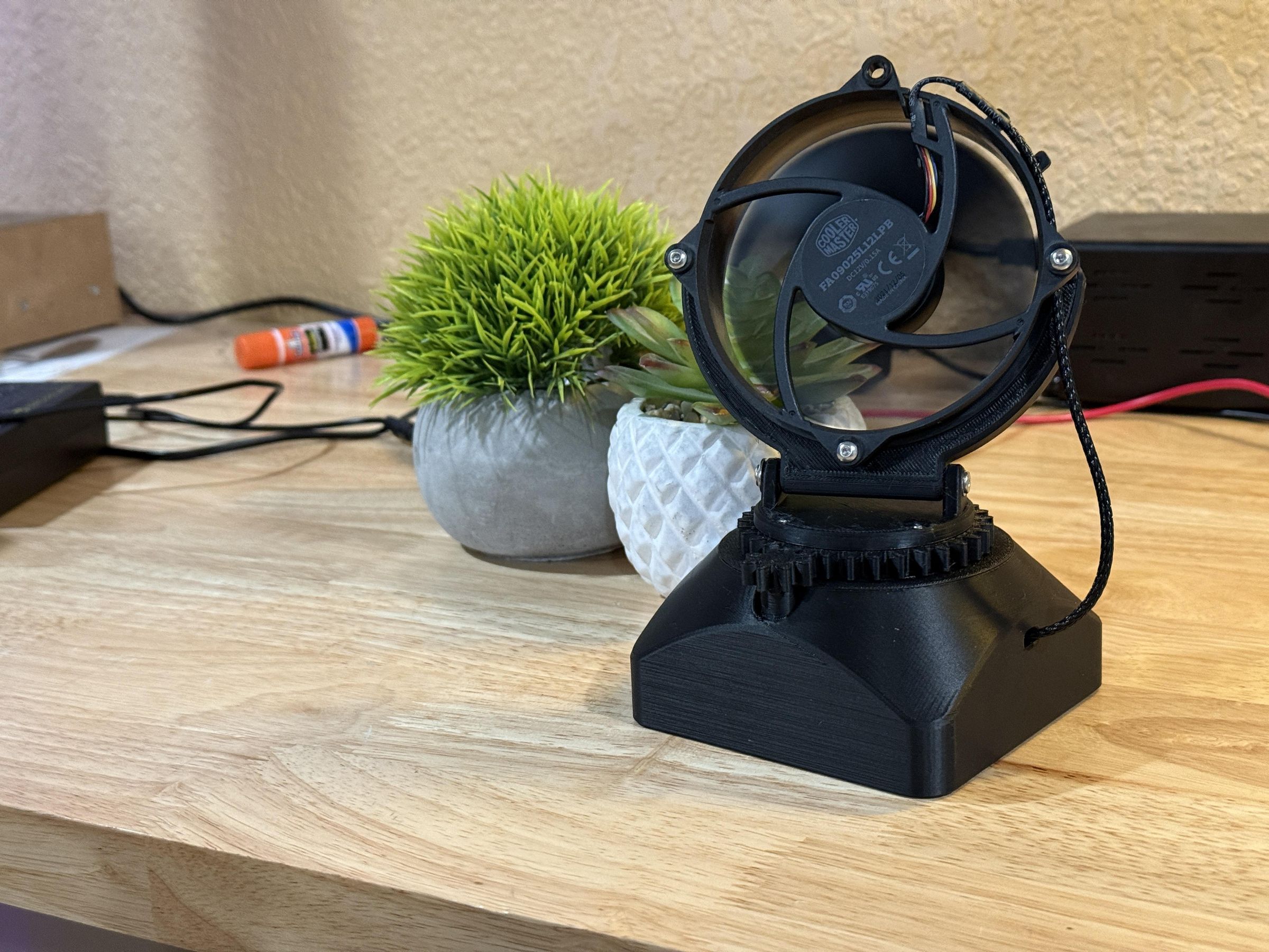
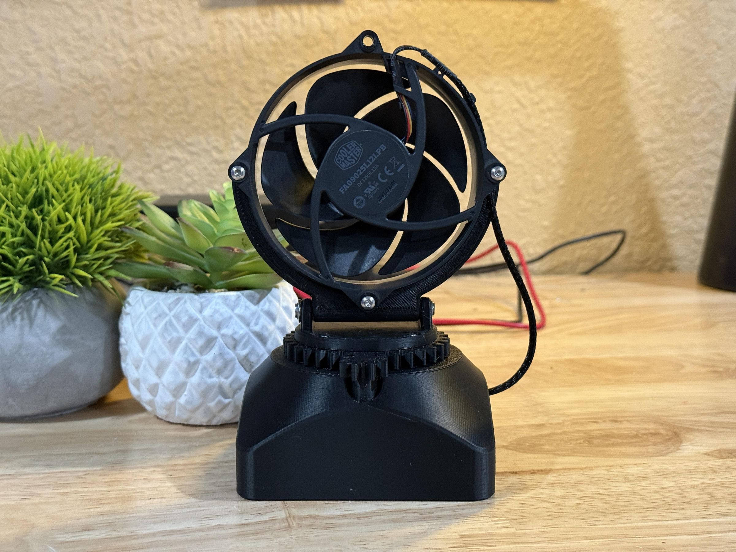
During the hot summer months, finding an effective solution to cool down is critical for comfort and productivity. However, in small spaces like dorm rooms or offices it may not be practical to implement full air conditioning units or large fans. In these scenarios, a simple desk fan can provide much needed relief while taking up little room. I wanted to find a way to receive as much cooling as possible from a small form factor desk fan, making work on hot days easier.
As a PC enthusiast, I realized I had multiple leftover CPU coolers (The ones that come included with AMD Ryzen CPUs). These coolers were exactly designed to produce ample airflow and cooling in a compact package. So I thought that repurposing one into a desk fan would make good use of the fan electronics.
I noticed that many standing fans have a feature where they can rotate back and forth to evenly distribute the airflow in an area. I wanted to implement this oscillating function into my desk fan to provide maximum airflow to the user.
This Instructable features the design and build process of a product that implements the aforementioned features, serving as a simple beginner electronics project, or simply a resourceful way to cool down during the summer.
Supplies
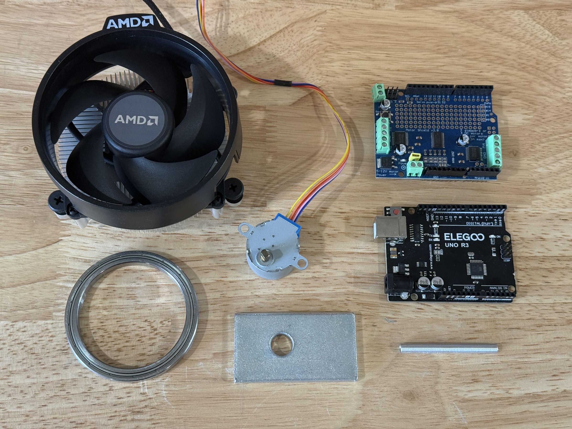
Supplies:
- 3D Printer Filament (PLA/PLA+)
- AMD Wraith Stealth Cooler (Or similar)
- Arduino Uno
- Adafruit Motor Shield V2
- Stepper Motor (28BYJ-48 12V)
- 12V Power Supply
- 55mm Ball Bearing
- Metal Weight
- 50mm M3 Standoff
- (3x) M3x30mm Bolt
- (4x) M3x20mm Bolt
- (6x) M3x14mm Bolt
- (3x) M3x8mm Bolt
- (2x) M3x6mm Bolt
- (4x) M3x5mm Bolt
- (15x) M3 Washer
- (7x) M3 Nut
- Electrical Tape
- Glue
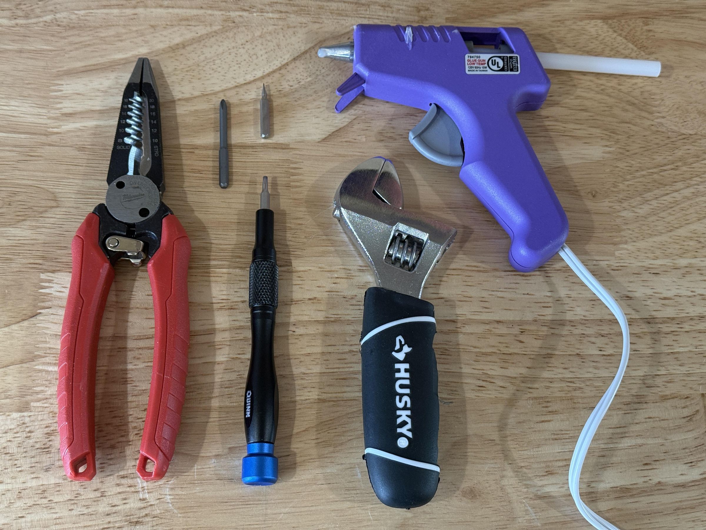
Tools:
- 3D Printer
- Computer
- Screwdriver (Hex, Philips, & Flat)
- Wrench/Pliers
- Wire Cutter/Stripper
Software:
- CAD Software (Fusion/Onshape/Solidworks)
- 3D Slicer (OrcaSlicer, Bambu, etc...)
- Arduino IDE
CAD
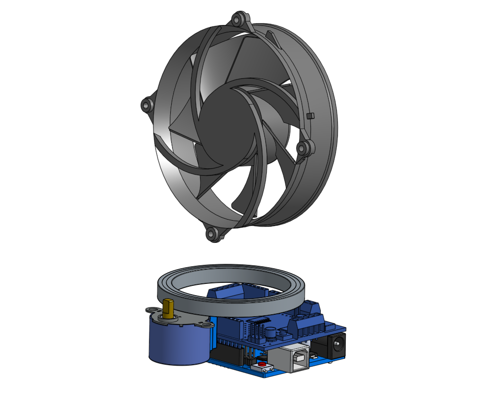
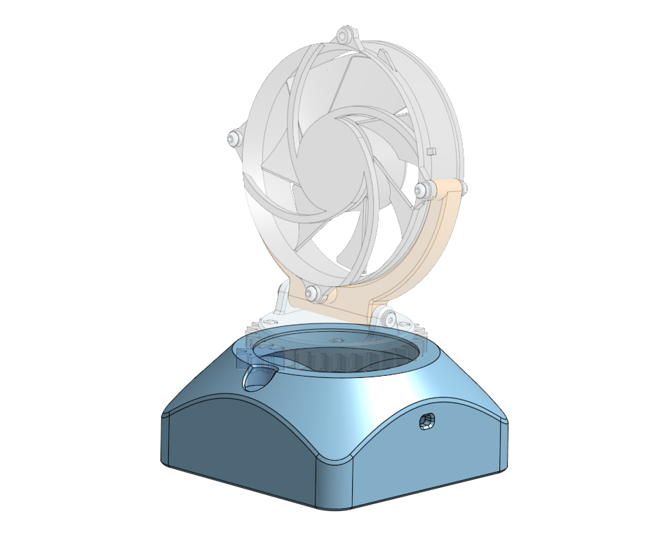
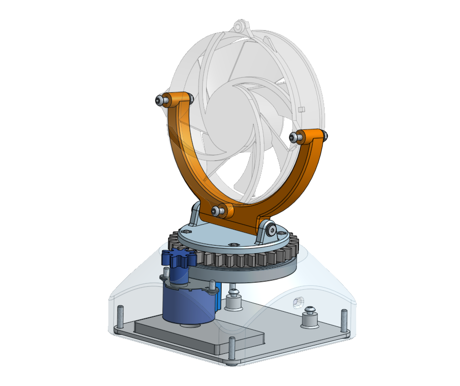
I began the CAD process by importing 3D models of all the off-the-shelf components I planned on using. This project was made with materials I already had on hand, however the components are very common and low cost. I arranged the electronics into the general shape that I wanted, with the fan rotating above the bearing and the Arduino/motor arranged compactly below.
The fan is actually positioned backward to how most would expect, as it is designed to intake air onto the heatsink, so the back of the fan is the side that needs to face the user.
Then I was able to create a "shell" to encapsulate the electronics and mount the bearing. The bearing and motion components for the fan all have a round profile, however the Arduino favors a rectangular enclosure so I used a large round chamfer to transition from a circular form at the top to a square form on the bottom. This large 45 degree chamfer also allows the part to be 3D printed upside down, which eliminates any sharp overhangs.
Afterward I was able to design the power transmission for the oscillating function. I created a small pinion gear that slips onto the stepper motor shaft, engaging with the flat spots on the shaft. This gear meshes with a larger gear that spins in the bearing and connects to the fan mount. The size difference between these gears also creates a gear reduction, resulting in smoother motion. The fan mount is on a simple pivot to provide adjustable fan tilt.
Finally there is a removable plate at the bottom which has standoffs for mounting the Arduino, and a space for the metal weight. This plate is removable for installation and maintenance.
CAD Assembly
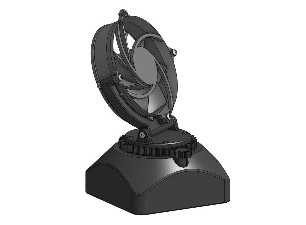
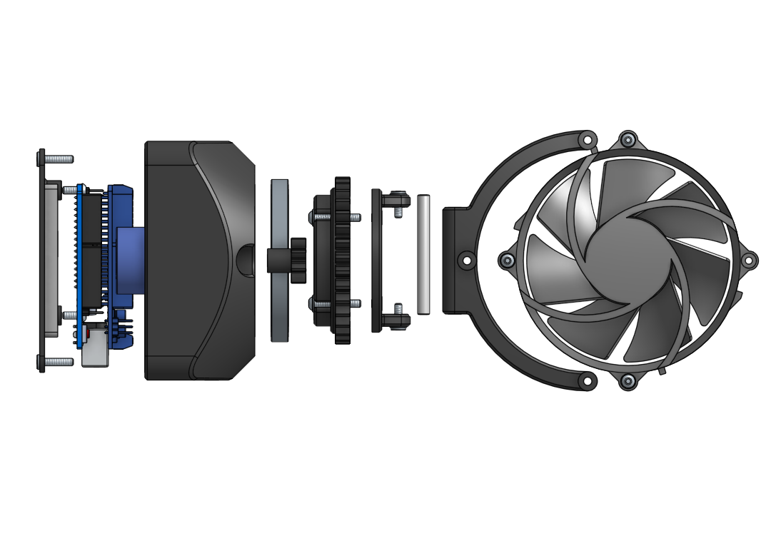
All of these parts come together in the final CAD assembly. However, in order to better visualize how they will interact in the real world I implemented accurate rotational joints for all the moving components.
The result is that I can spin the pinion gear and watch the fan rotate with the correct gear ratio, and dial in the rotational limits before ever seeing it in real life. Understanding the limits of the machine ensures the fan wires wont be overextended and potentially damaged.
The fan tilt also has accurate adjustment, allowing me to asses the range of motion and evaluate if there are any issues such as center of mass/tipping.
The full CAD file is provided below if you wish to look further into how the whole assembly interacts.
Downloads
3D Printing
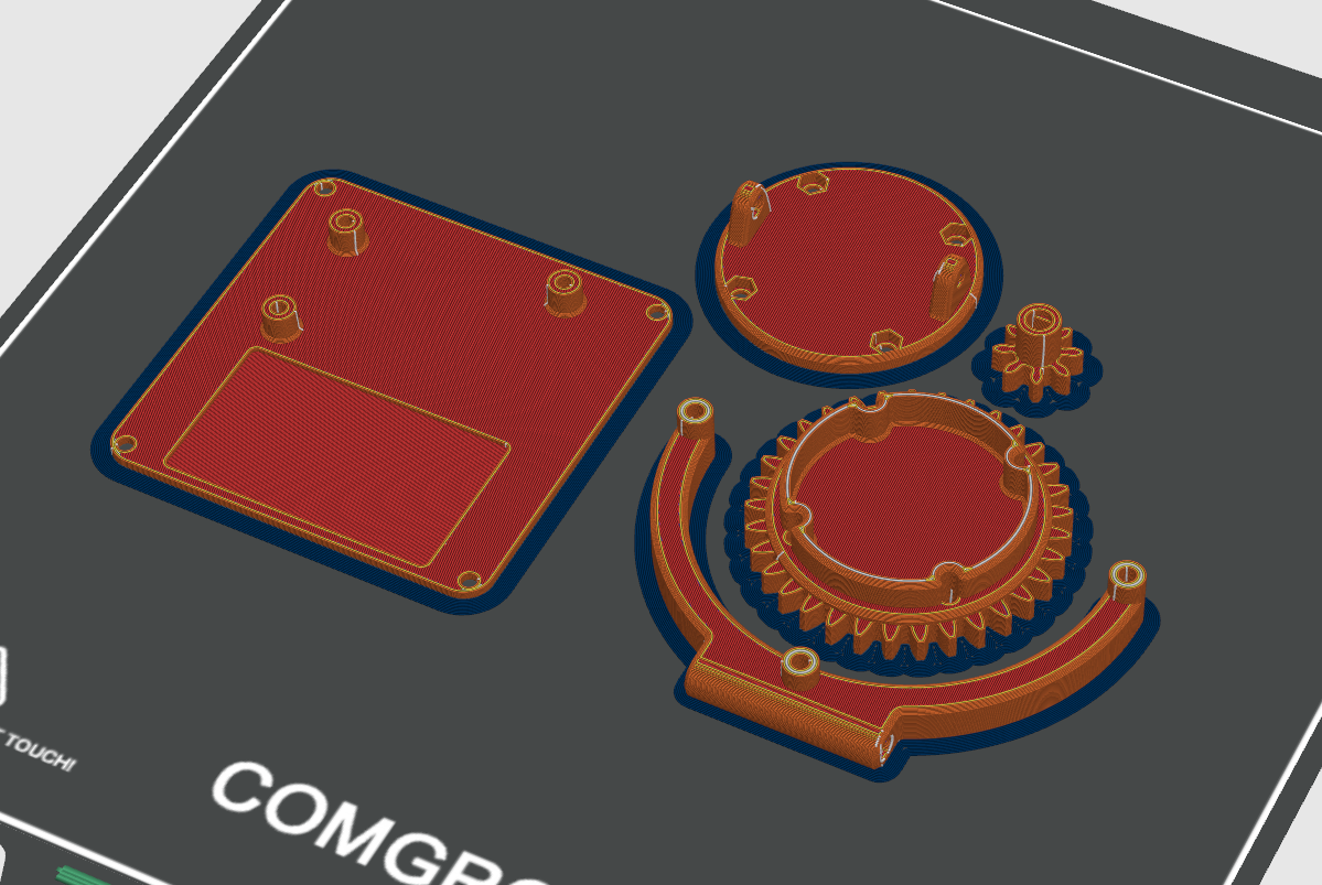
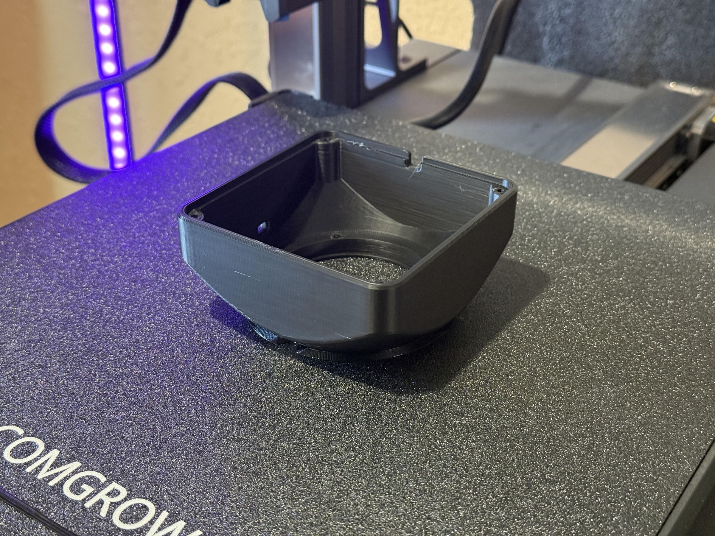
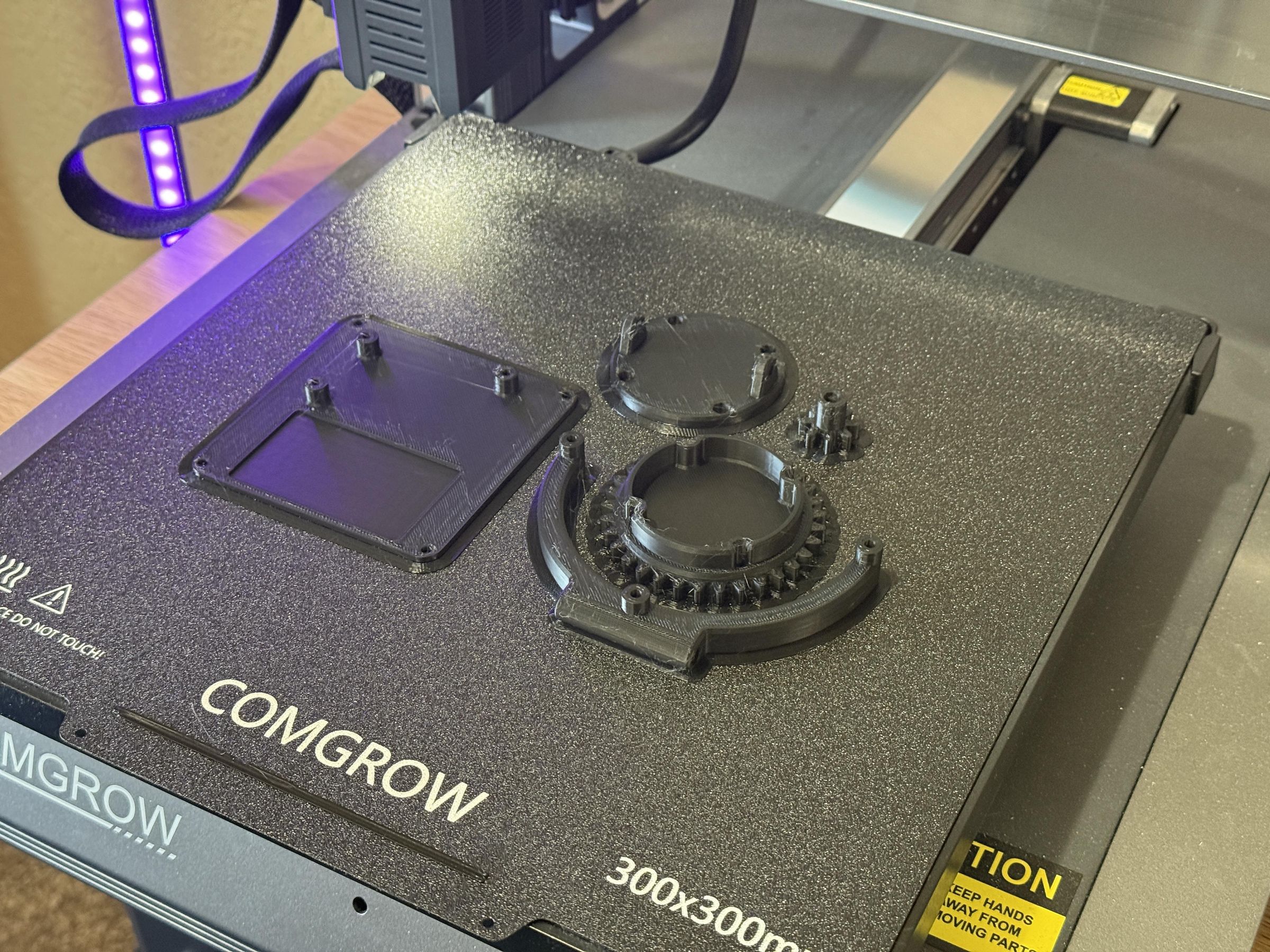
I started by importing all of the 3D printed parts into OrcaSlicer to prepare them for printing. I used Sunlu PLA+ 2.0 filament for all of the parts. The shell was printed with 10% infill but everything else used 20% infill as parts like the gears will experience more force and could benefit from extra strength. I added a brim to the outside of each part to reduce warping and increase adhesion to the build plate.
Every part was designed to print without the use of supports, making the process a lot simpler and more accessible. There is also the option to implement different color filament to add a stylized element or better match a specific desk setup.
All of the STEP files for the 3D printed components are provided below:
Disassemble CPU Cooler
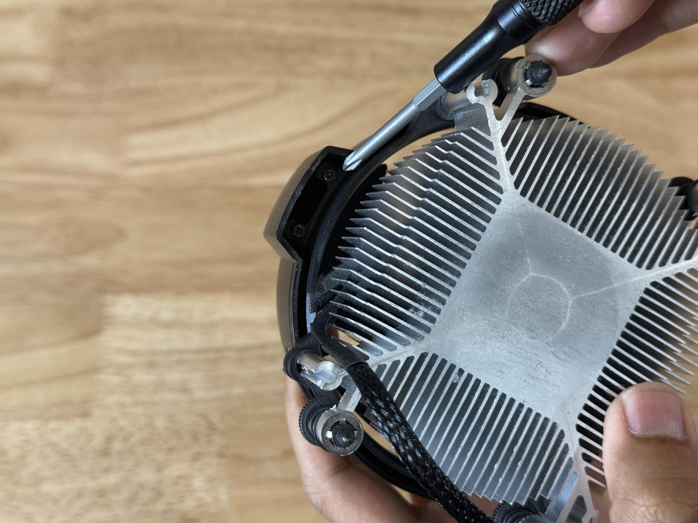
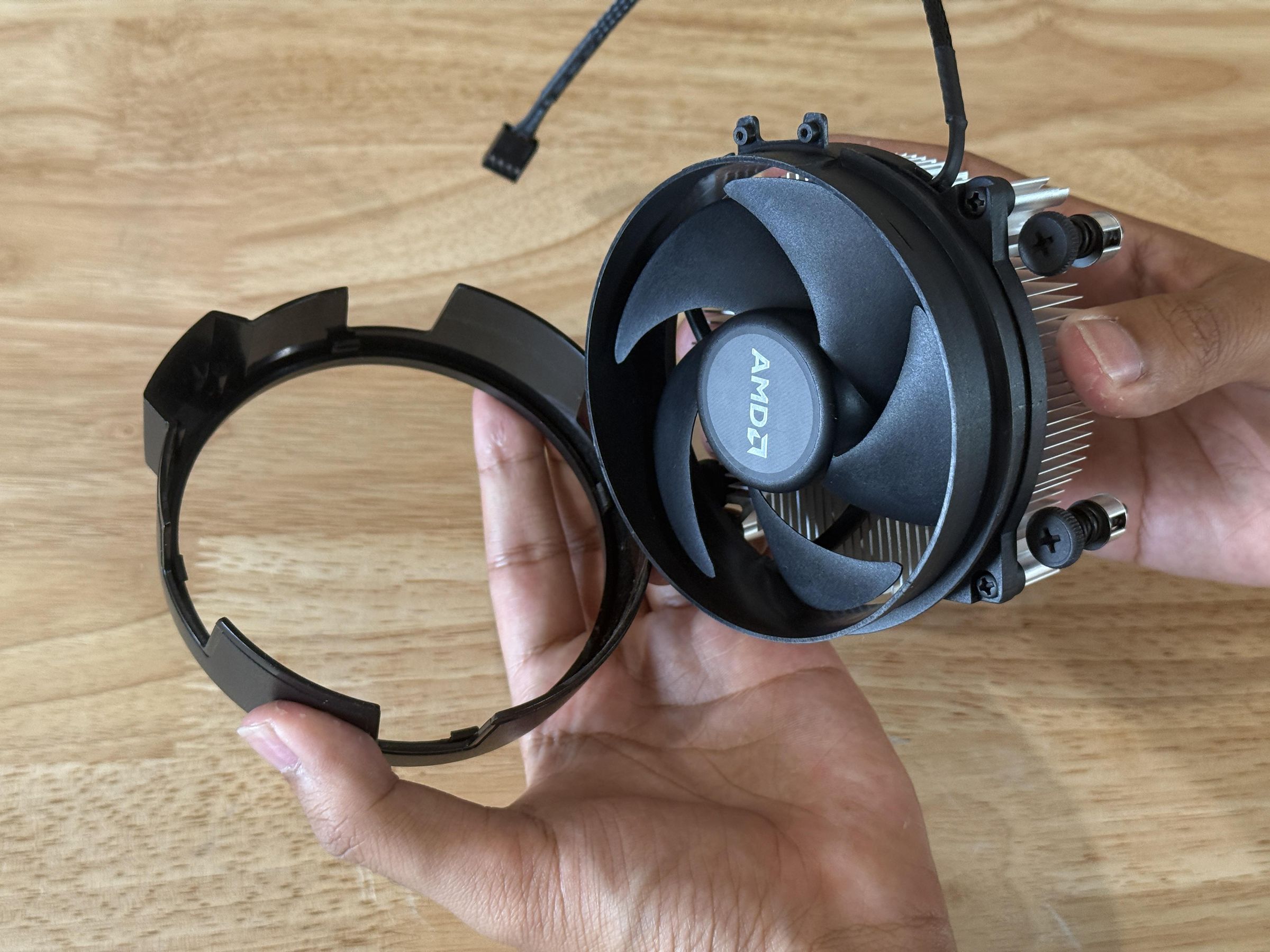
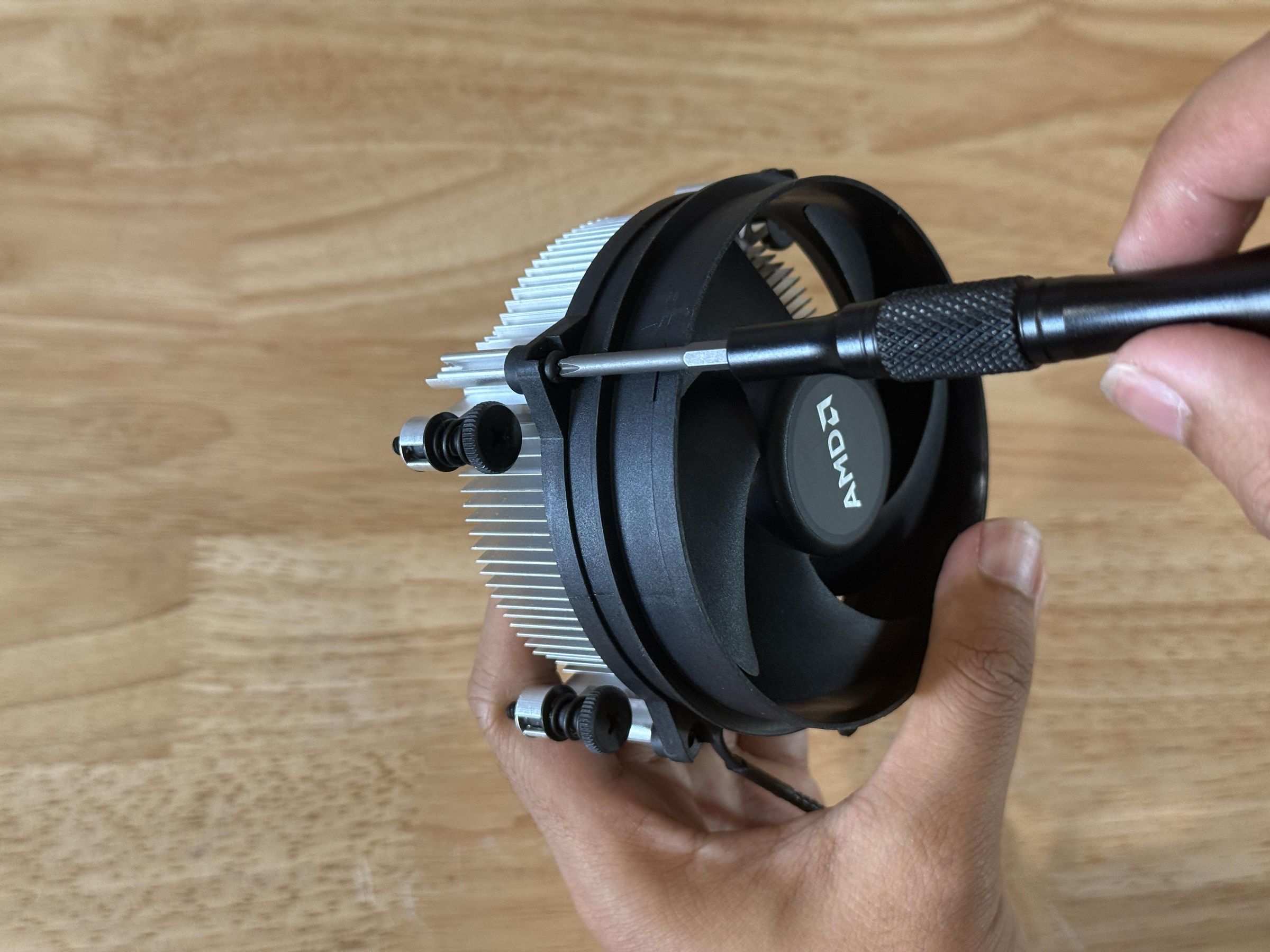
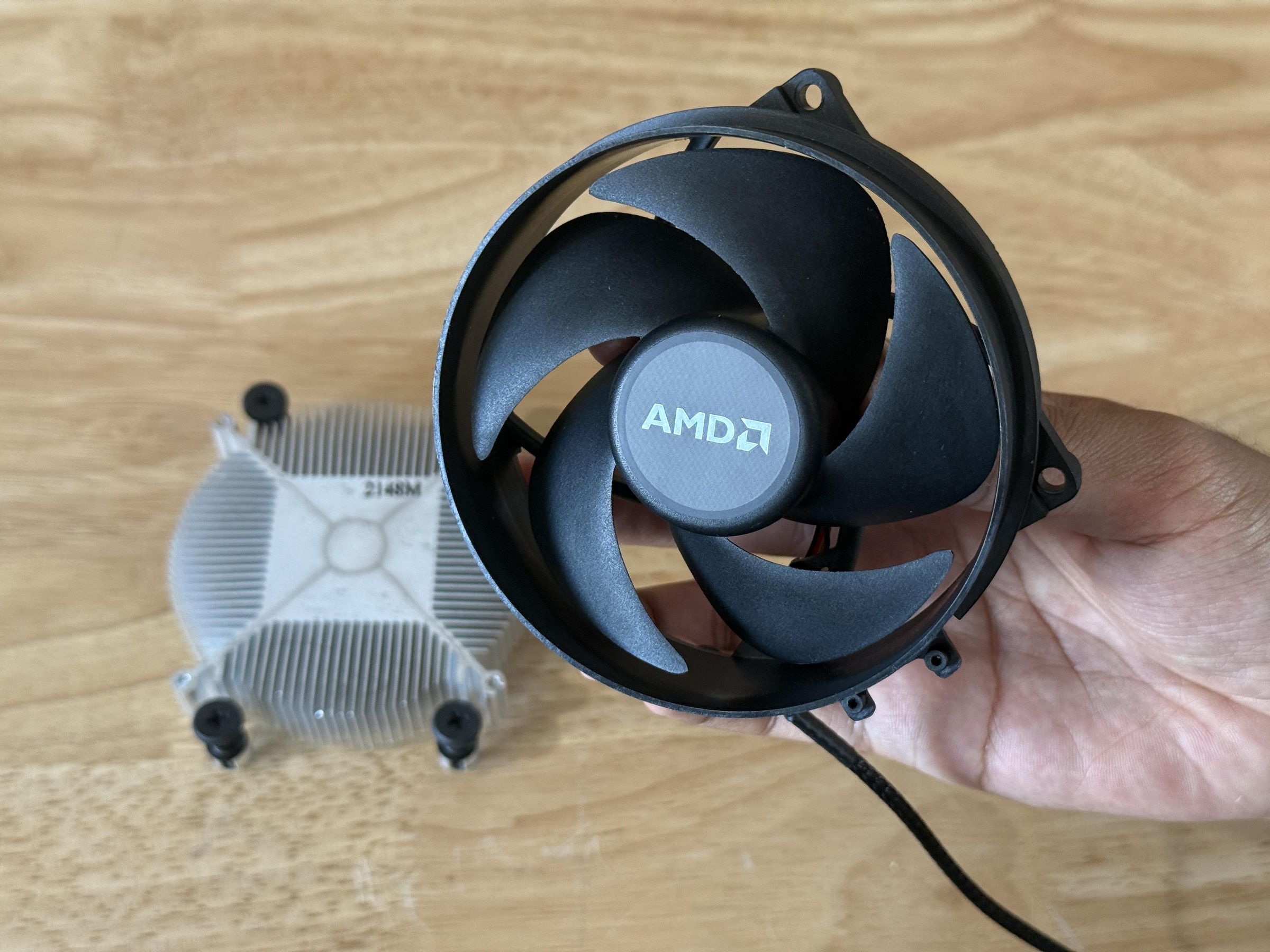
Start by unscrewing the two Philips screws from the underside of the CPU cooler. This allows you to detach the decorative cover which is held on by clips.
Then unscrew the four small Philips screws around the top of the fan, separating the actual fan from the heatsink.
Attach Fan Mount
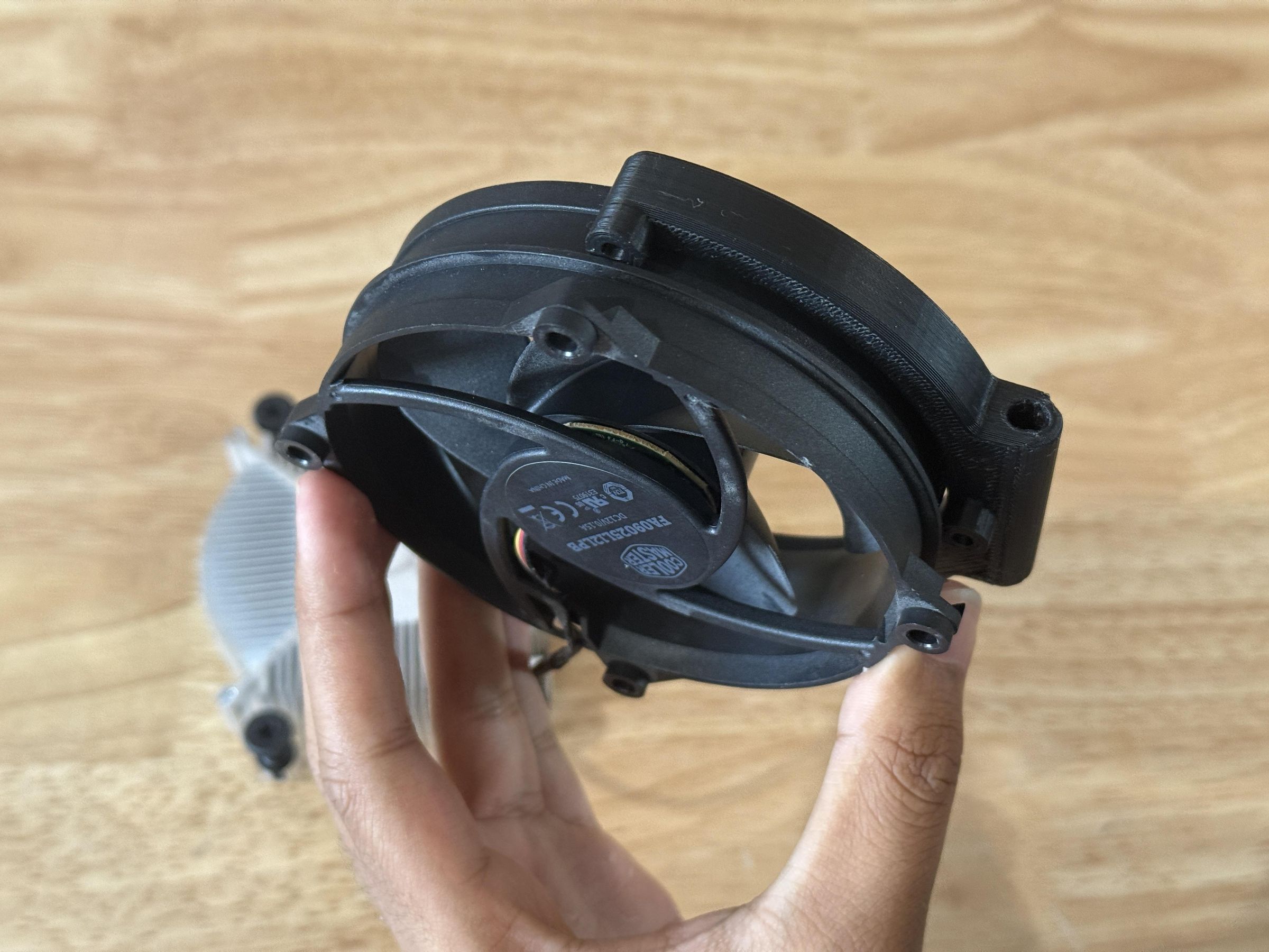
Upon trying to align the 3D printed fan mount to the holes on the actual fan, I realized it had a large lip that was not present in the CAD model and was preventing the standoffs from reaching the mounting holes. (1st Image)
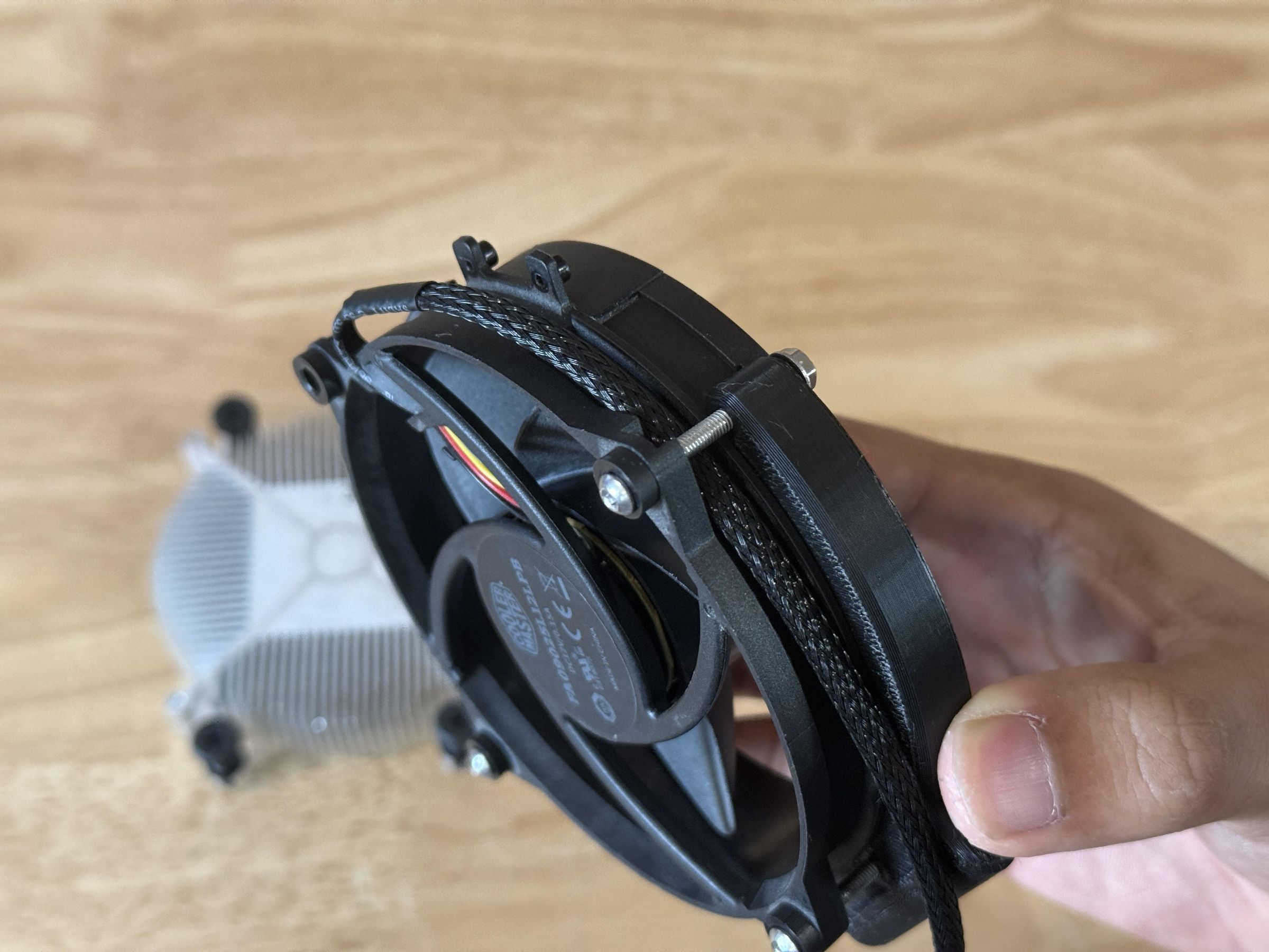
To fix this, I removed the standoffs in CAD, then reprinted the fan mount with the same settings. This allowed the mount to align properly and the bolts could pass all the way through. (2nd Image)
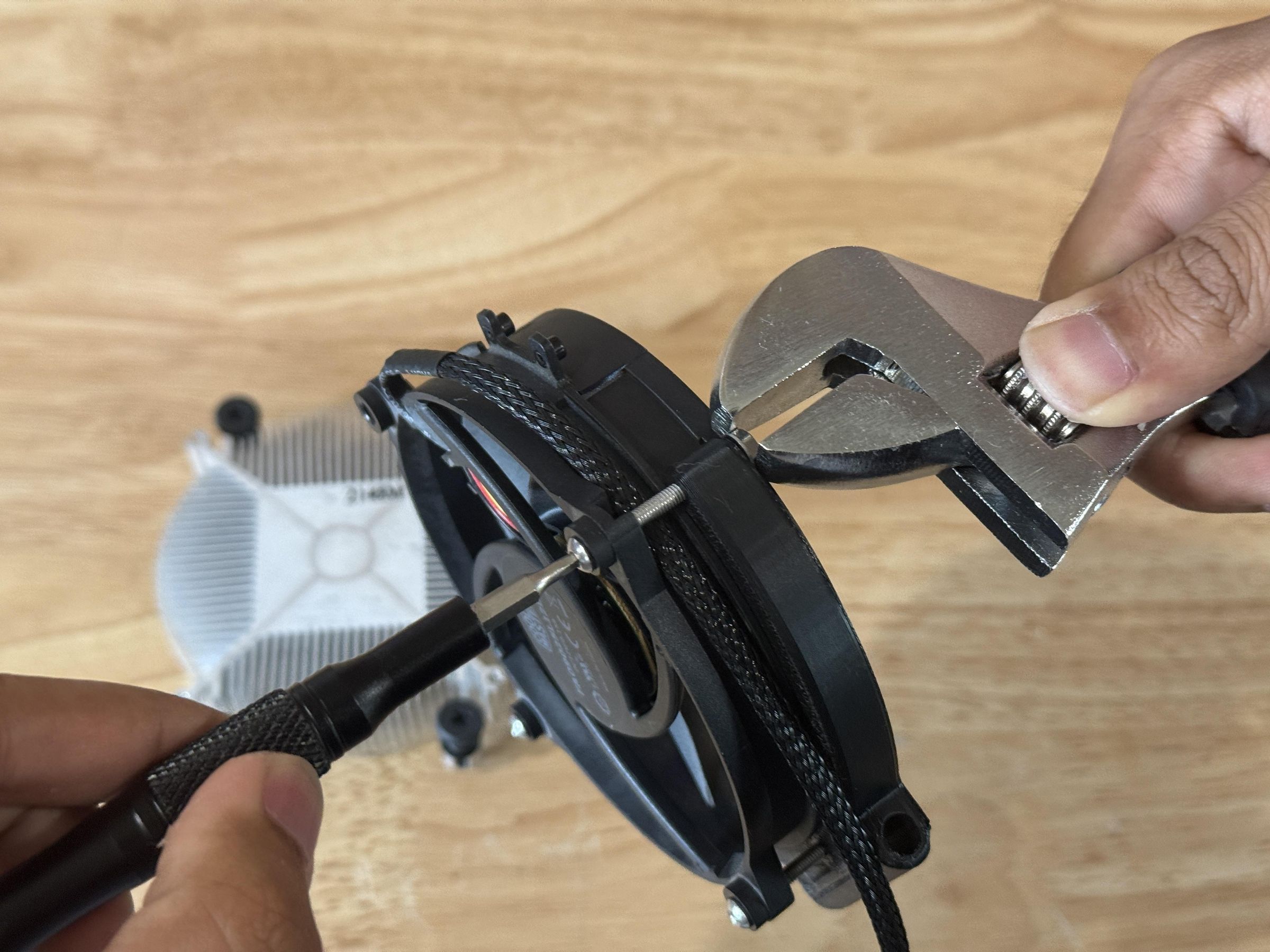
When attaching the fan mount, use three M3x20mm bolts with M3 nuts and washers to secure three out of four mounting holes on the fan. On the right side of the fan, tuck the fan cable underneath the bolt before tightening to redirect it towards the base of the fan.
Downloads
Attach Fan Pivot
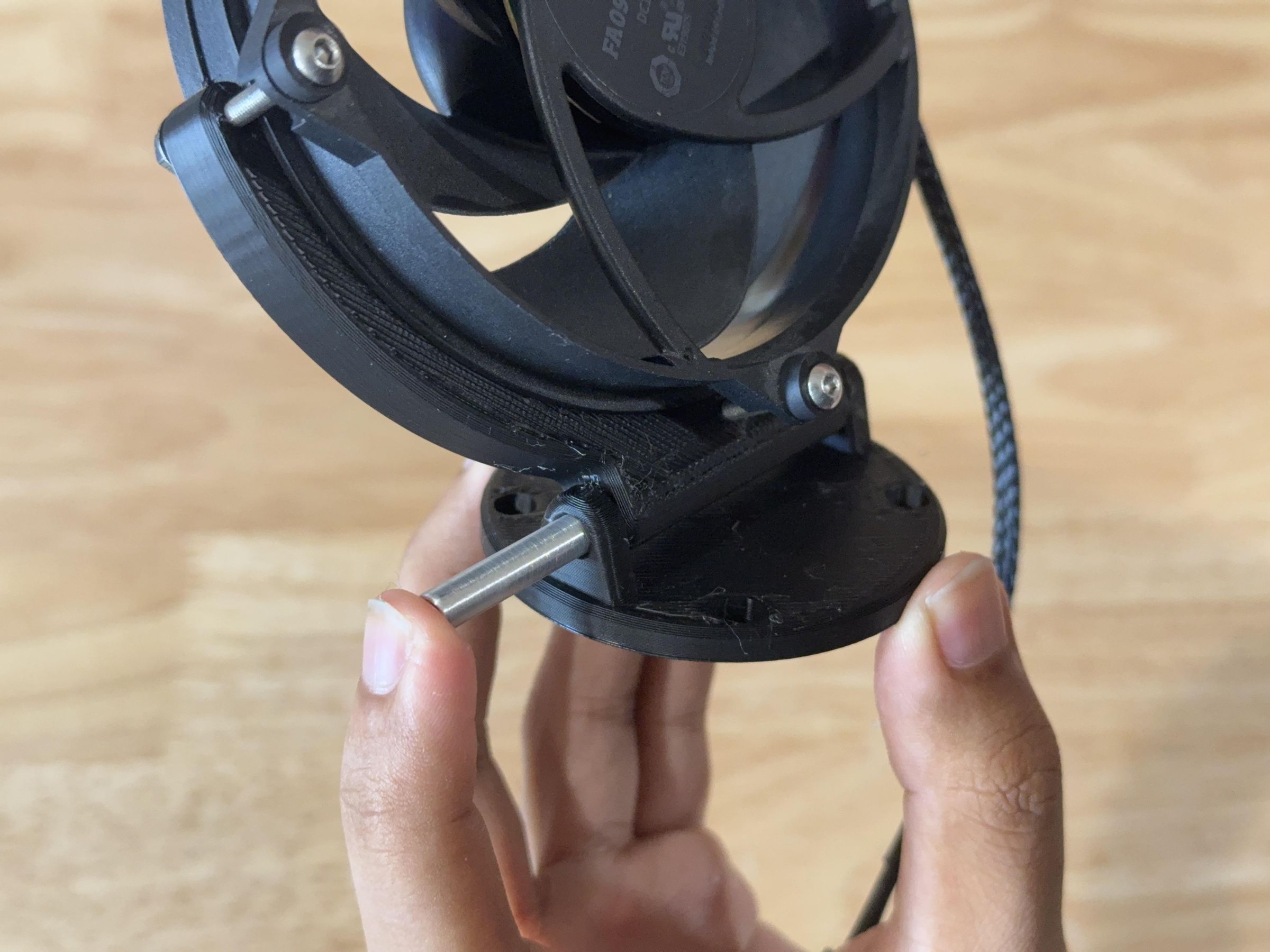
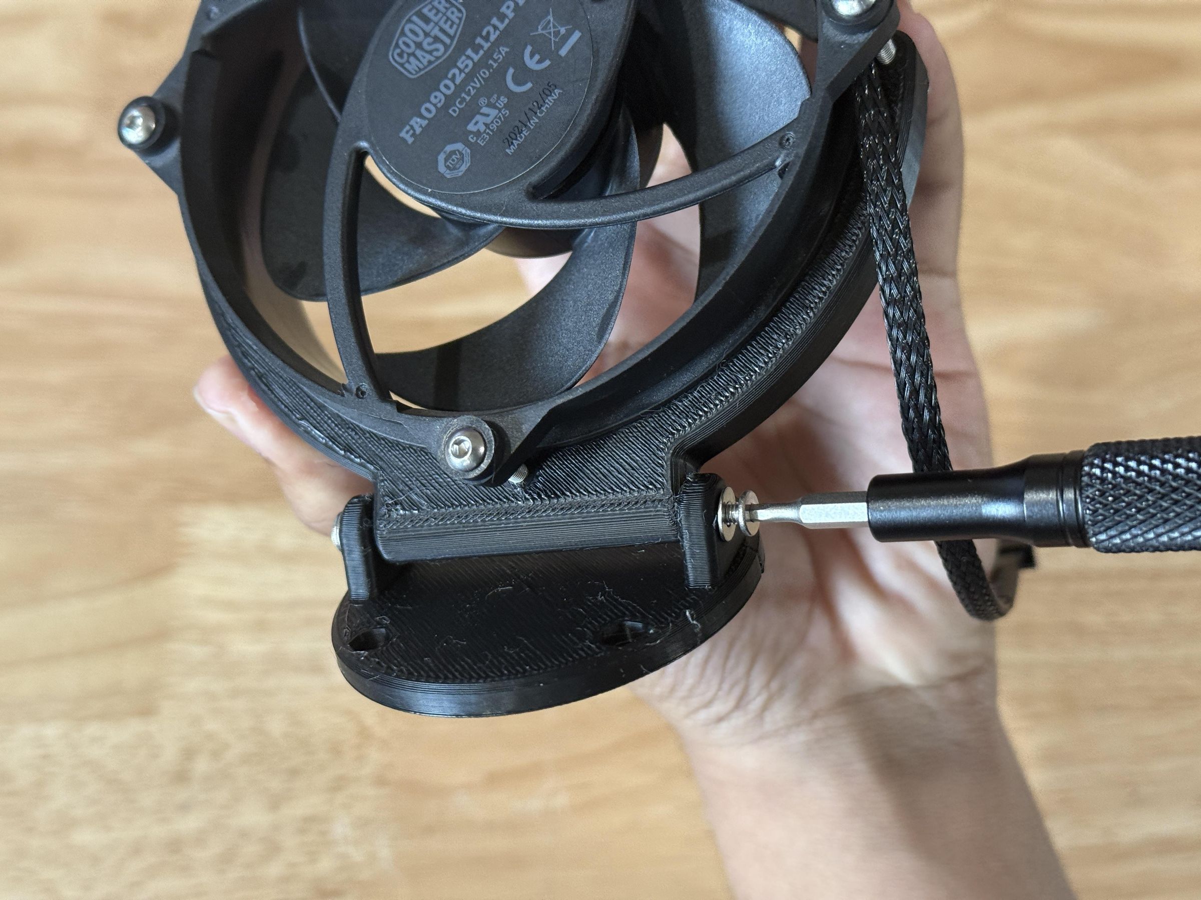
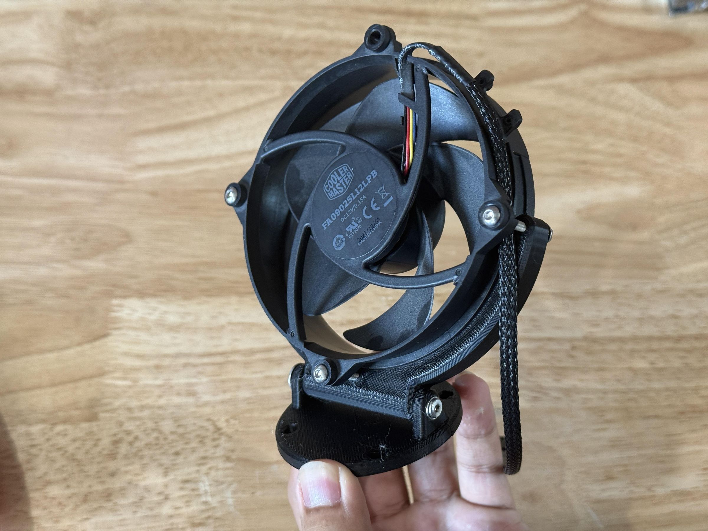
In order for the fan to tilt, it needs a strong pivot with enough resistance to hold itself up while still being adjustable.
Start by aligning the fan mount to the pivot and sliding an M3x50mm threaded standoff into the left side of the pivot. This should reach all the way through the fan mount.
Then secure both ends with M3x14mm bolts and washers, tightening until the pivot has enough strength to hold in any position.
Press Fit Nuts
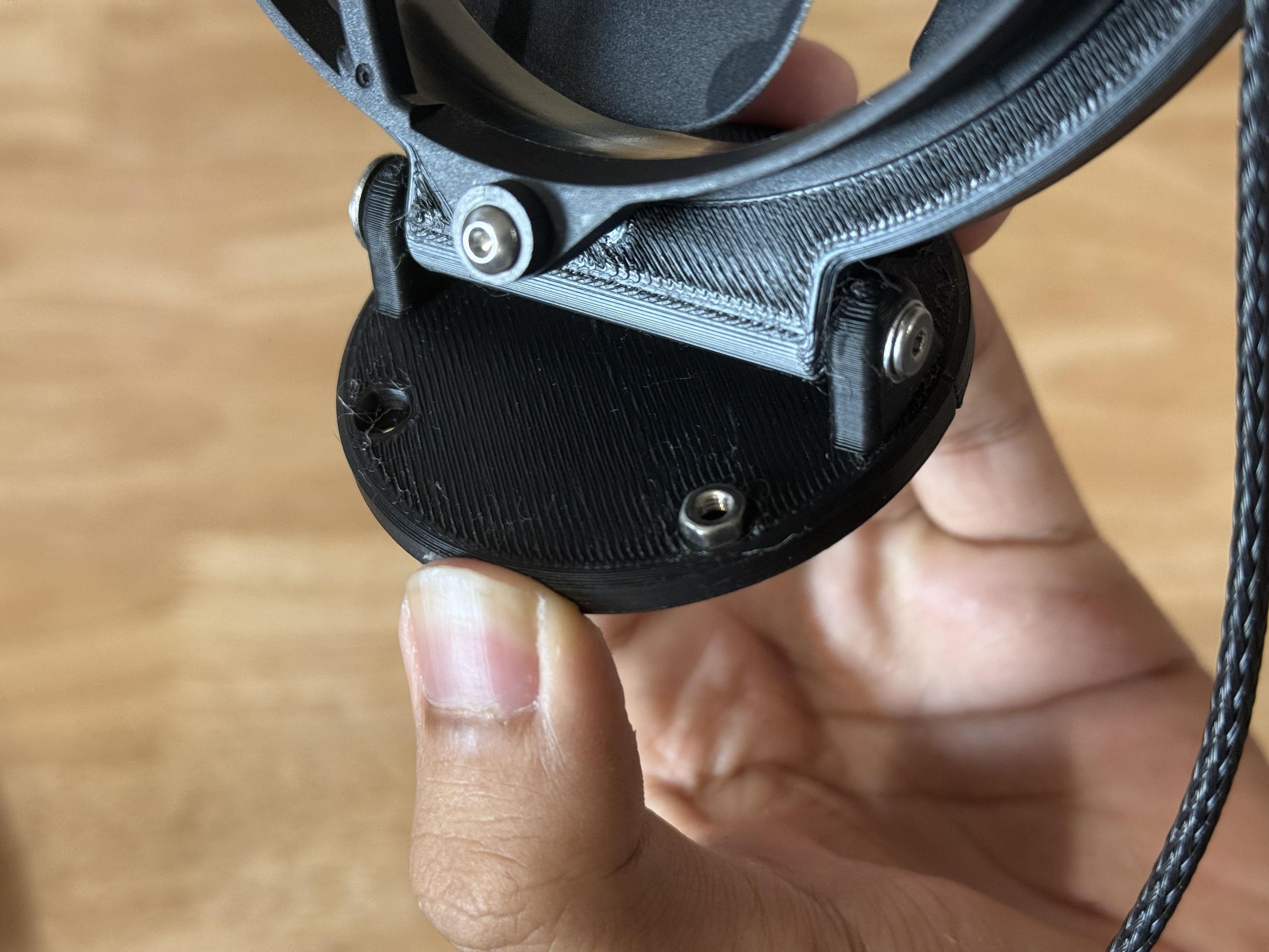
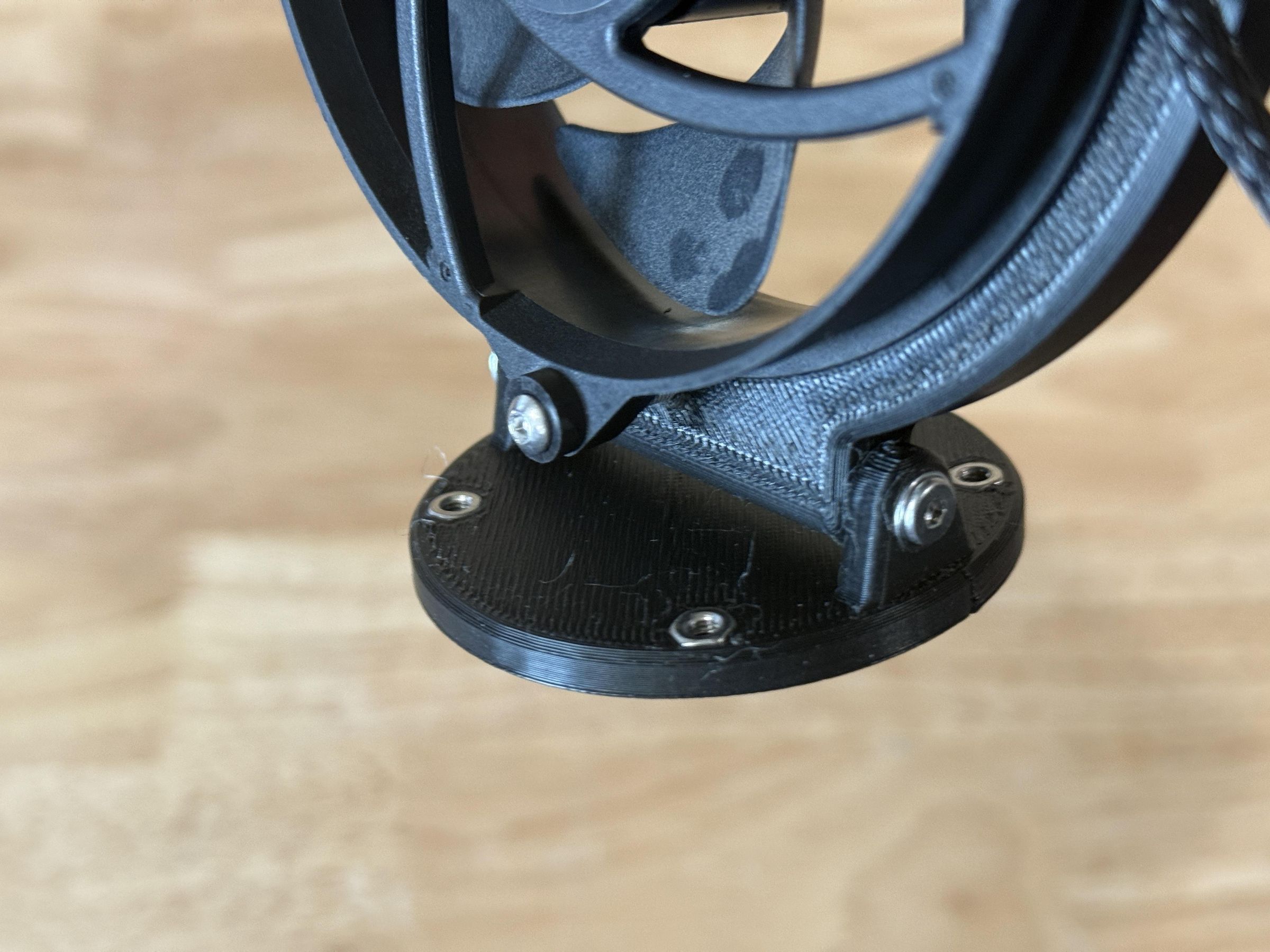
To prepare the pivot for installation, align an M3 nut into the hexagonal recess on top of the pivot plate. Then press it down into the print until it is flush with the top surface. Light force from something like a hammer may be required depending on print tolerances.
Repeat this process for all four M3 nuts around the pivot.
Install Bearing
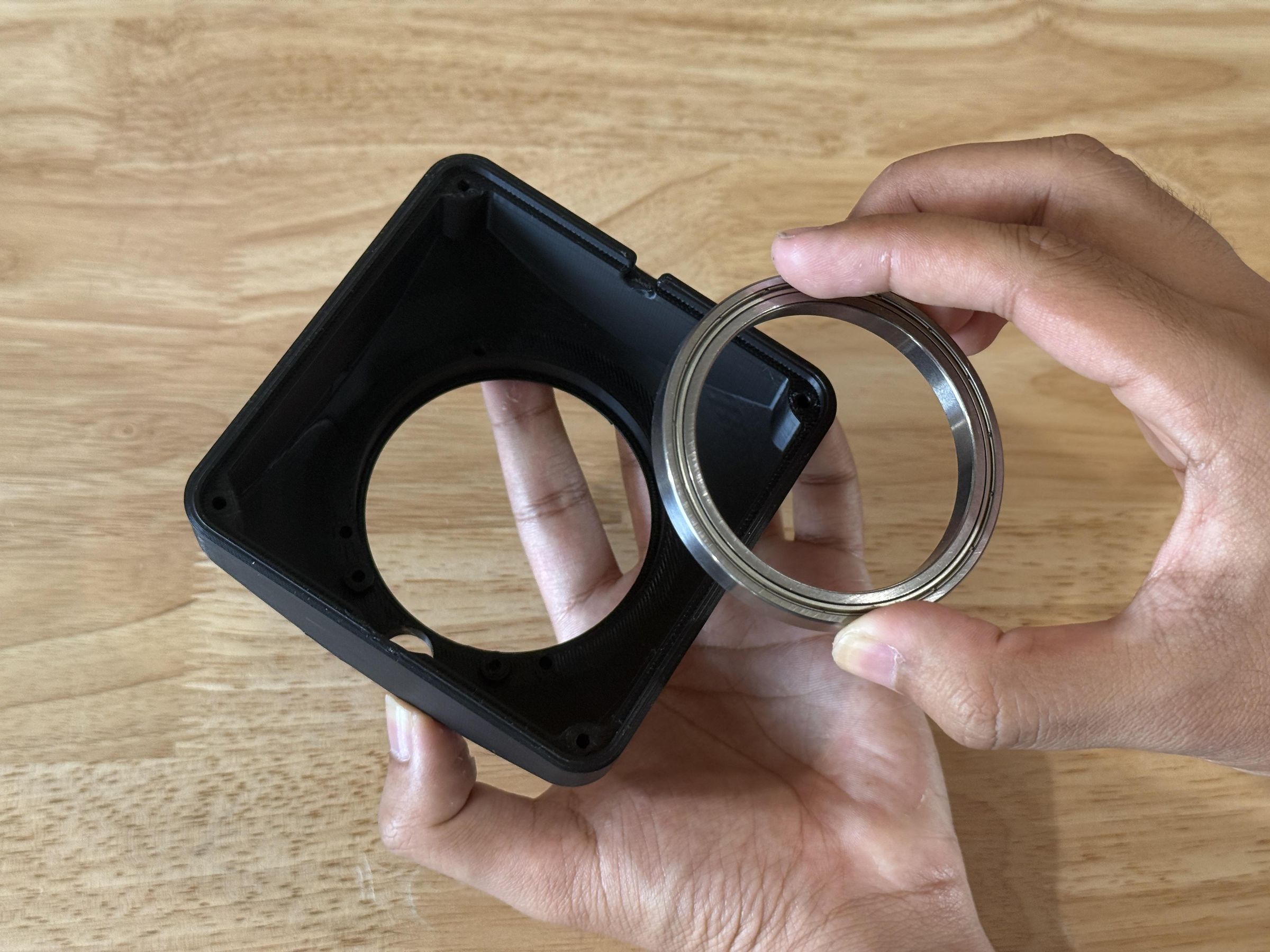
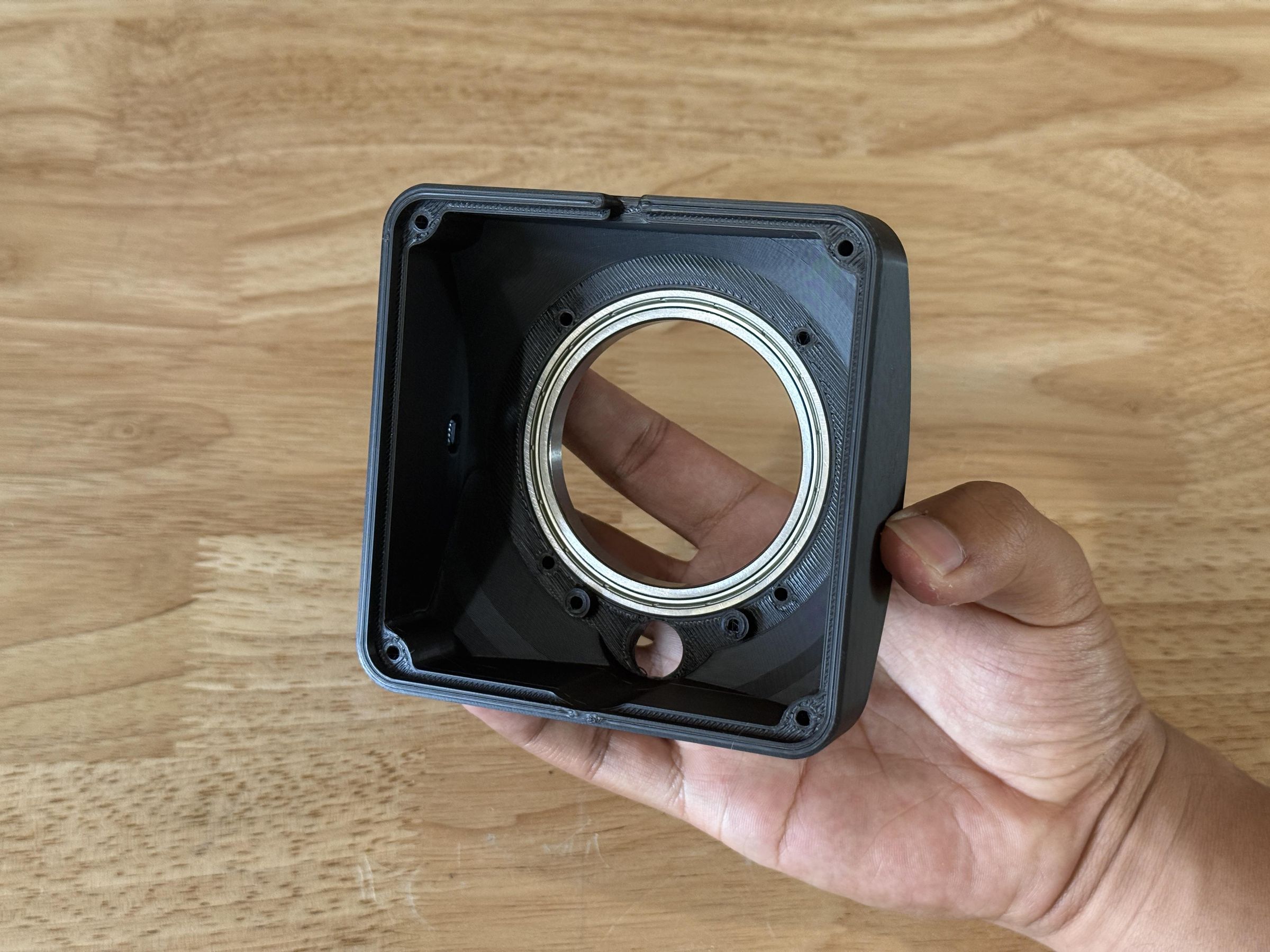
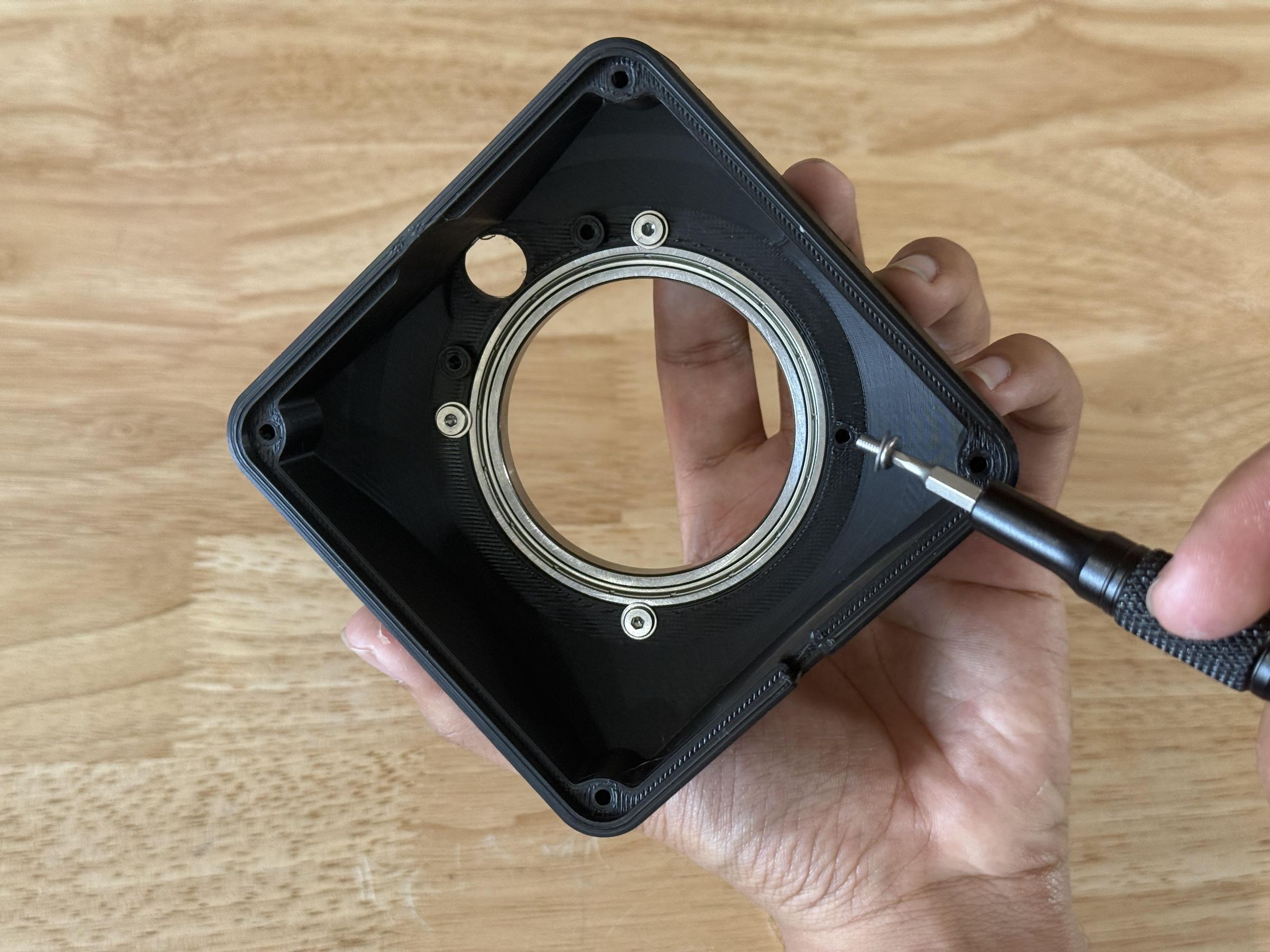
Press the 55mm ID bearing into the circular recess in the underside of the shell piece. This should be a press fit and the bearing should be able to hold itself in place.
However, in order to strength this connection, secure the bearing with four M3x5mm bolts and washers. The washers should be contacting the outer race of the bearing, preventing it from falling while still allowing smooth rotation.
Attach Stepper Motor

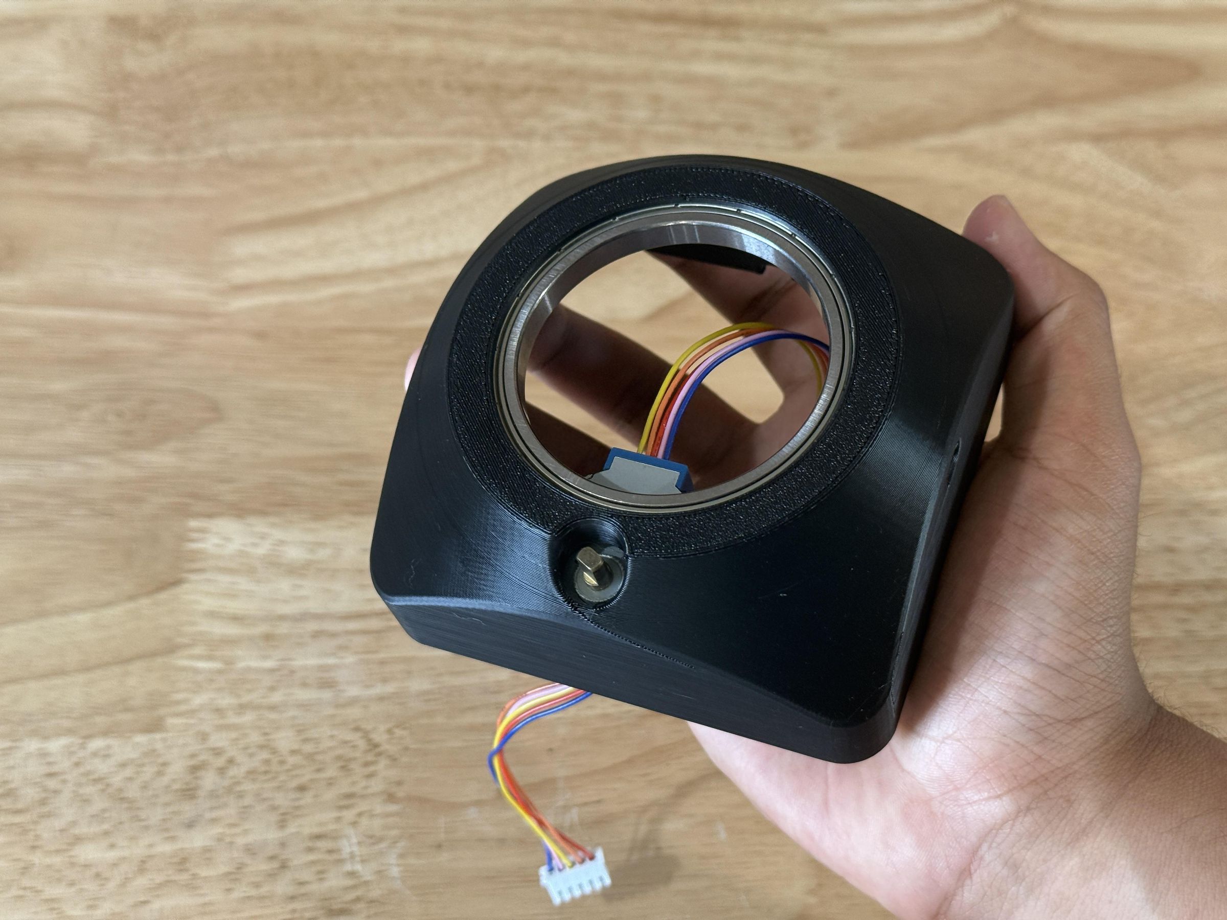
Align the stepper motor with the mounting holes on the underside of the shell and attach it with two M3x6mm bolts. The motor should be right up against the wall of the shell if aligned properly.
Also ensure the correct motor placement by checking that the output shaft is concentric with the small hole on the top side of the shell.
NOTE: Pictured in these images is the 28BYJ-48 stepper motor 5V version. However this must be replaced with the 28BYJ-48 12V version.
Secure Pivot Gear
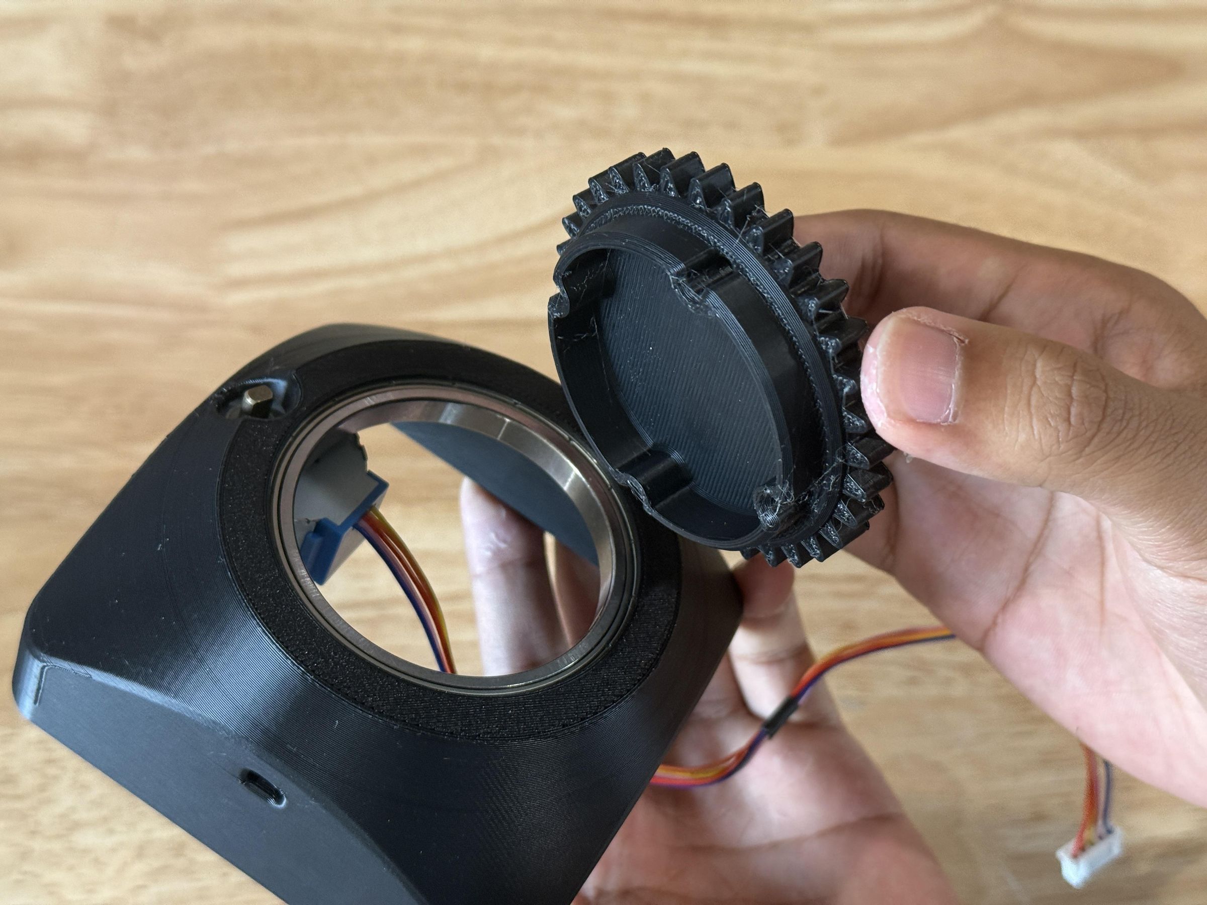
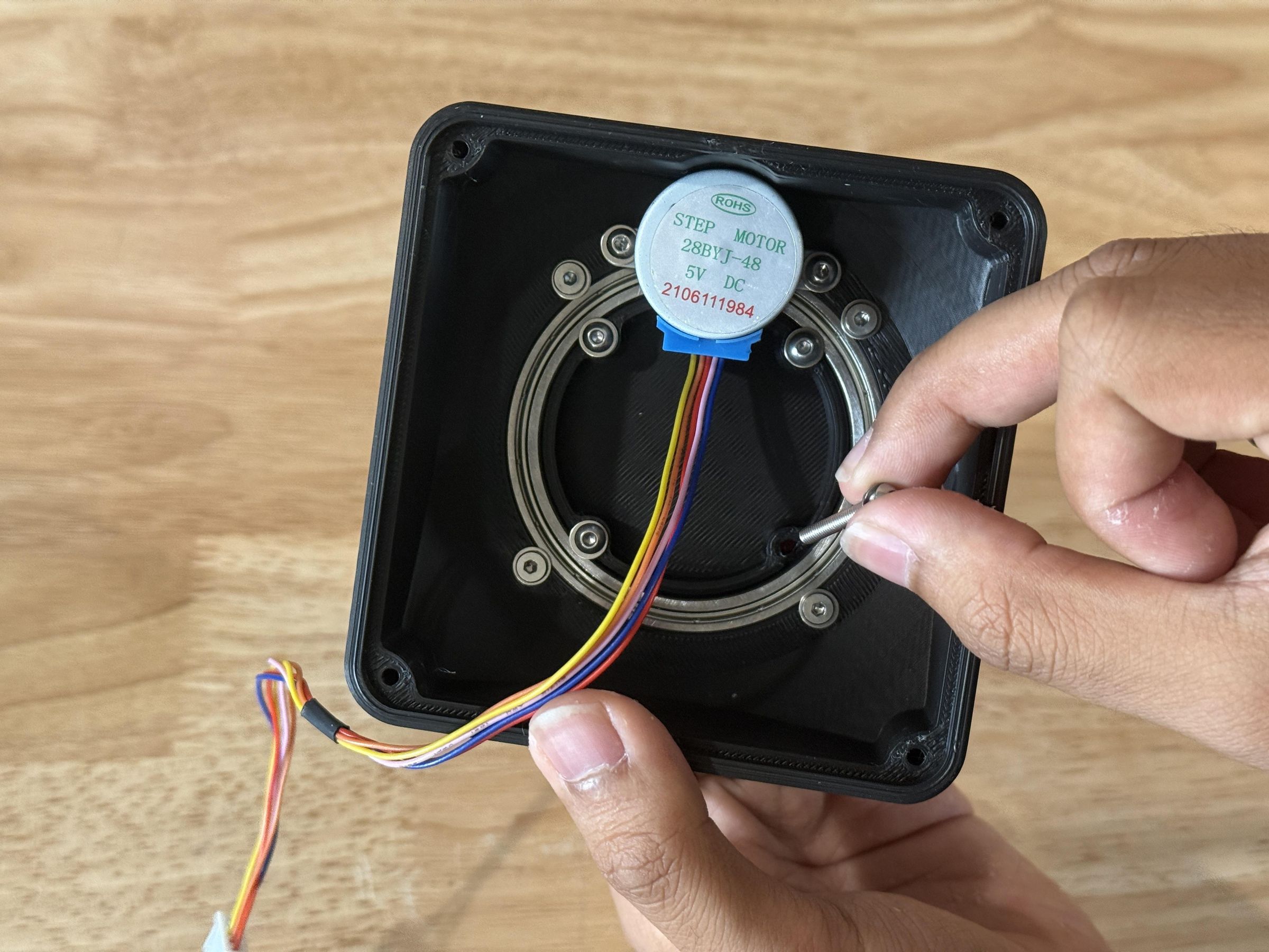
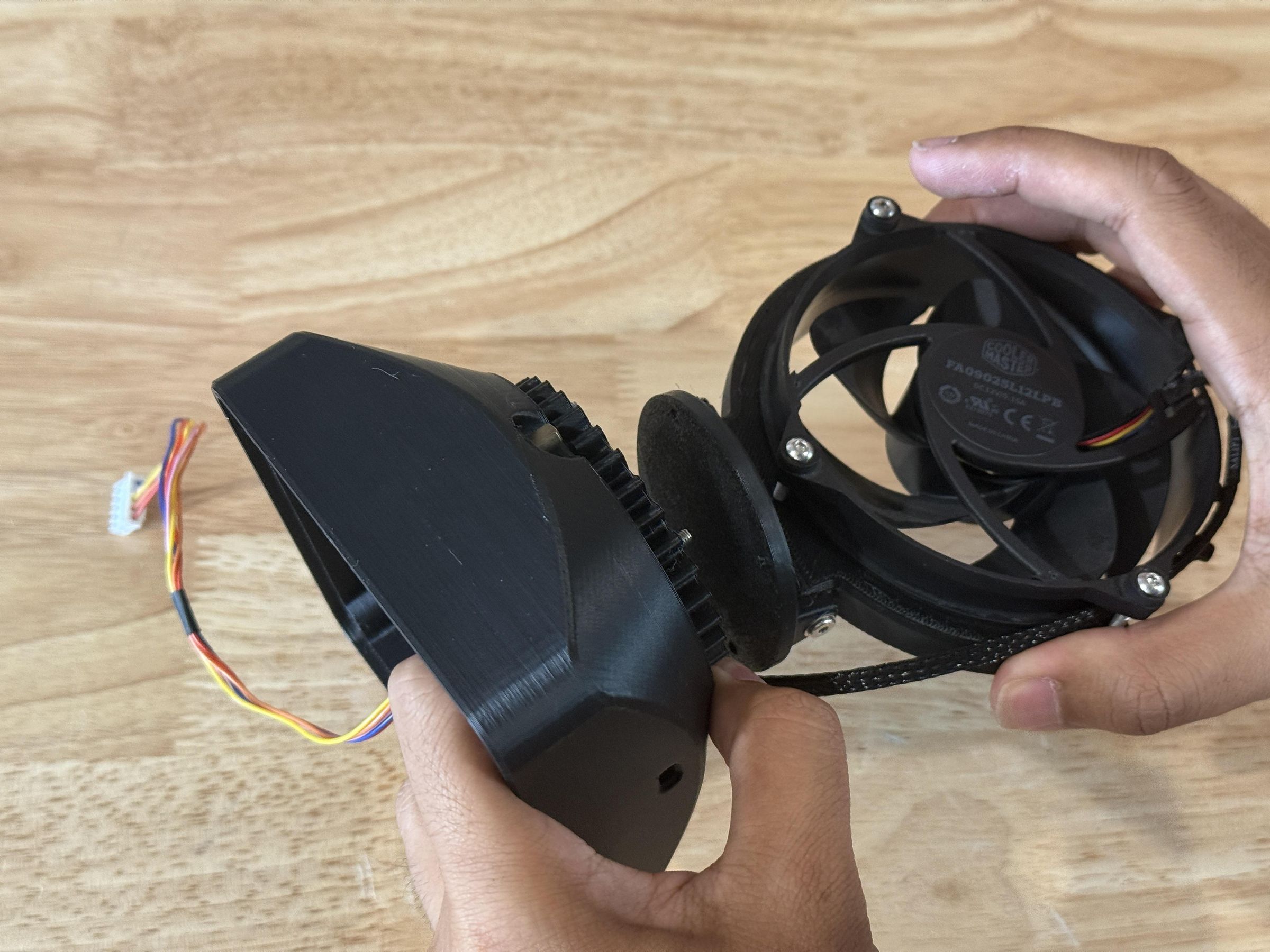
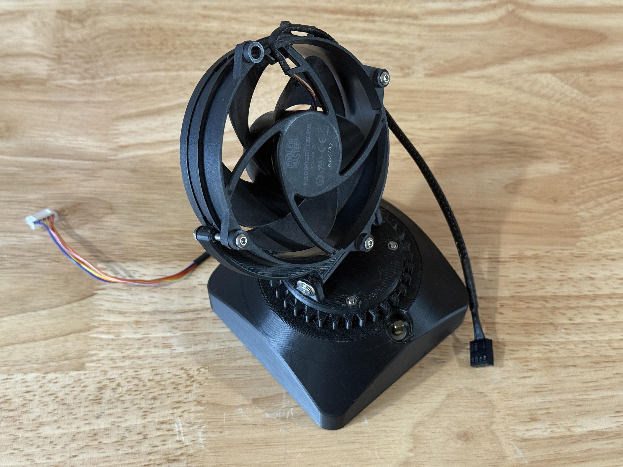
Insert the large gear into the inner race of the 55mm bearing. Then flip the assembly over while holding the gear in the bearing.
Then drop four M3x20 bolts and washers into the holes in the gear part. Bring in the pivot assembly and align the four holes with the bolts protruding from the large gear. Finally slide the bolts into place and tighten them until the pivot assembly is securely attached to the shell.
Ensure the fan and gear can still rotate freely and smooth, testing by turning it the full range of motion.
Attach Pinion Gear
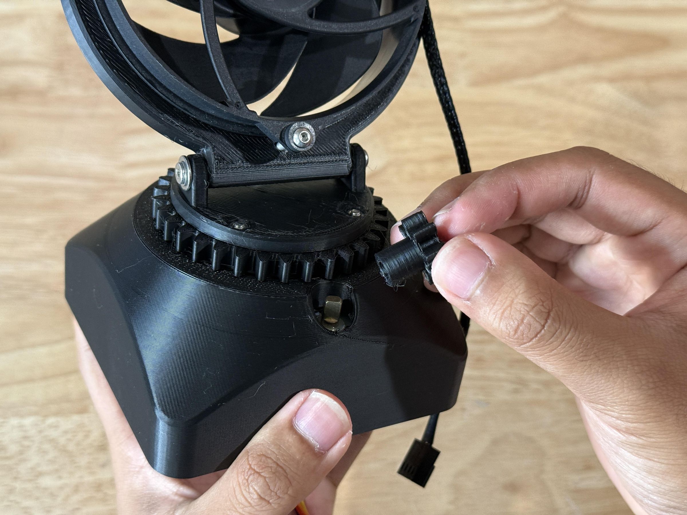
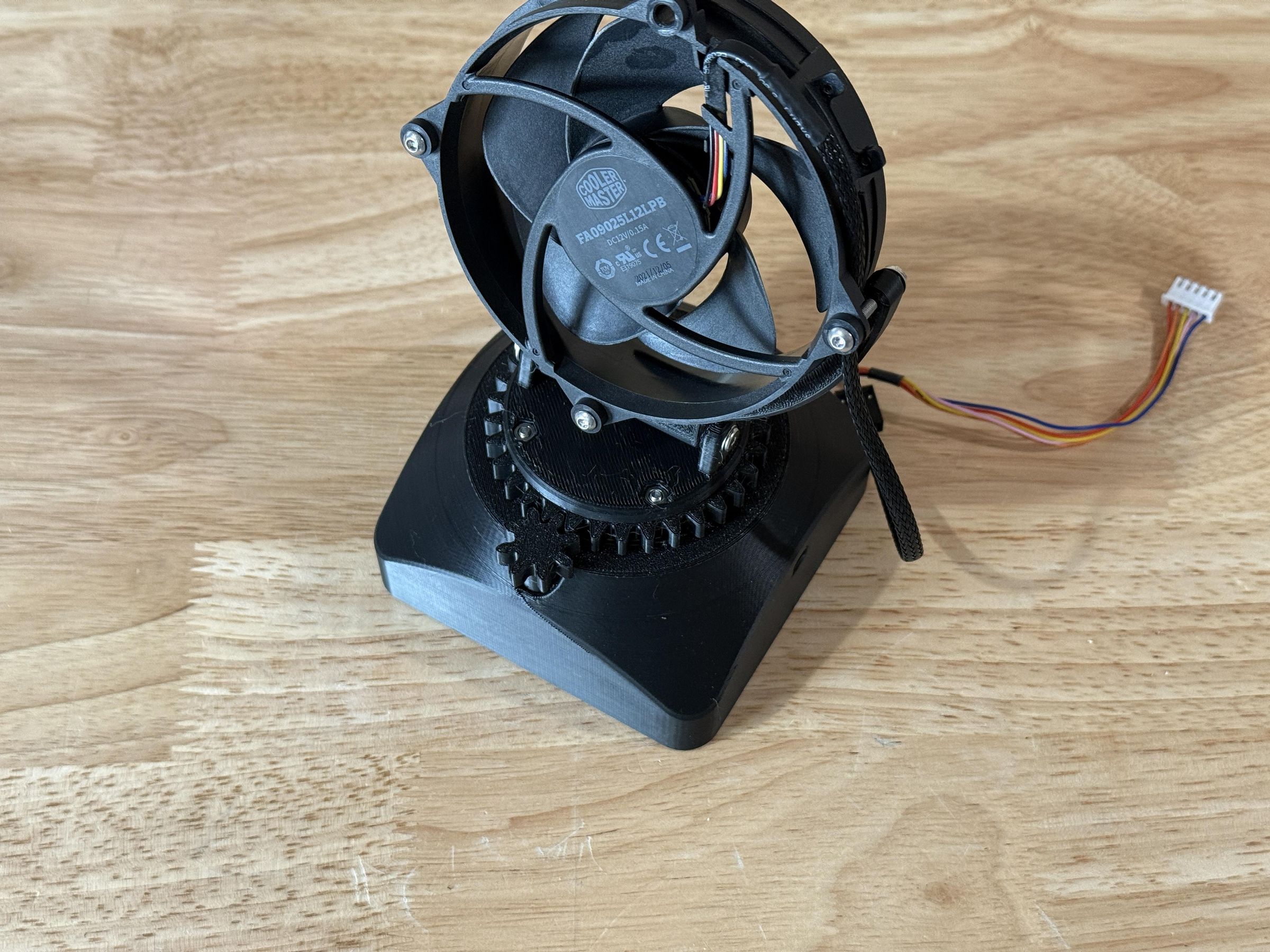
To prepare for attaching the small pinion gear to the stepper, rotate the large gear so that the front (previously back) of the fan is facing directly ahead towards the user. This will be the starting position for the oscillation.
Once the fan is aligned, acquire the pinion gear and look underneath to see the flat spots in the attachment hole. These need to mesh with the flat spots on the stepper motor shaft, so rotate the pinion gear accordingly.
Finally slide the pinion gear onto the shaft from above. You may need to slightly angle the large gear for the teeth to drop into place.
Add Weight
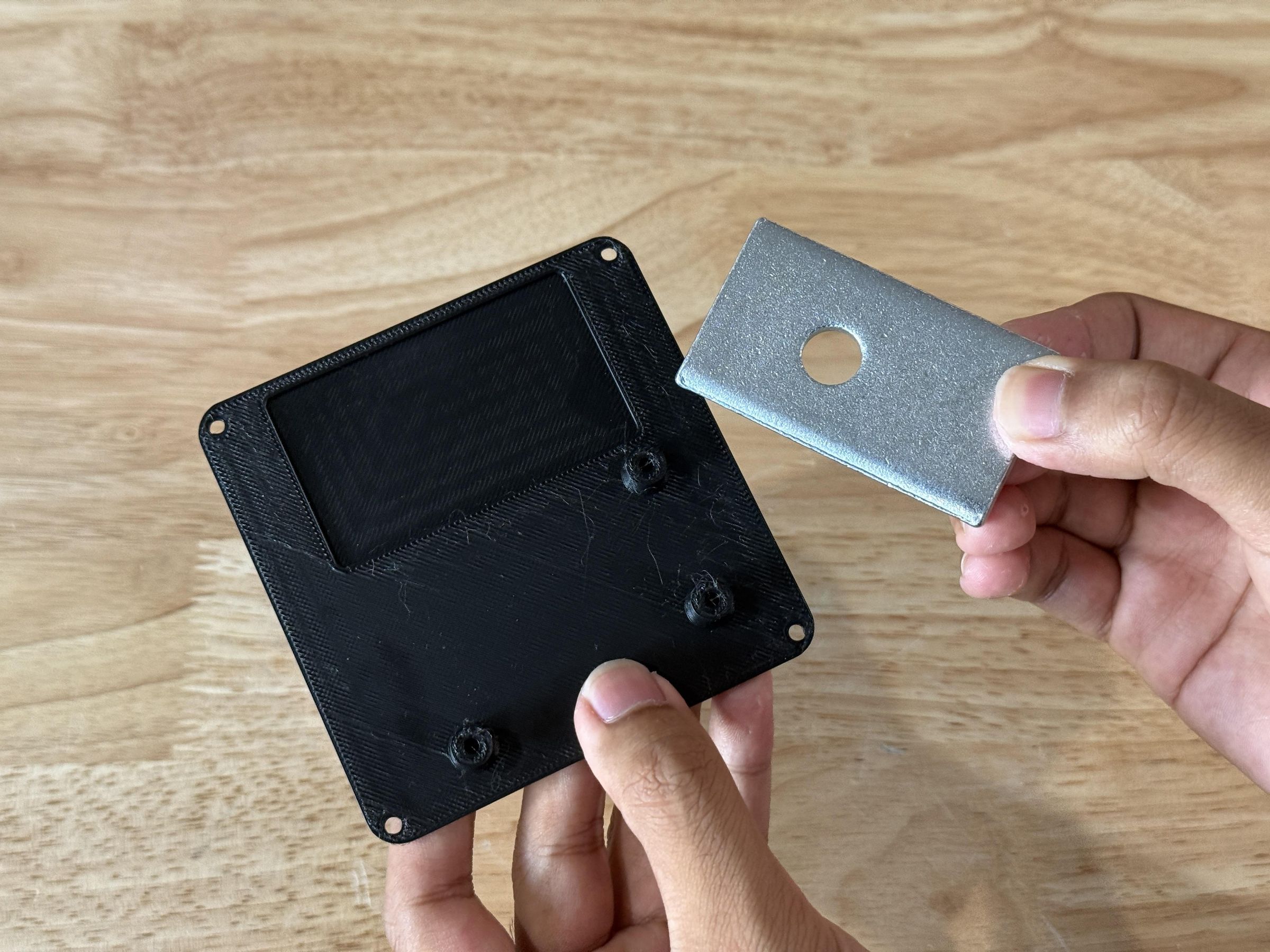
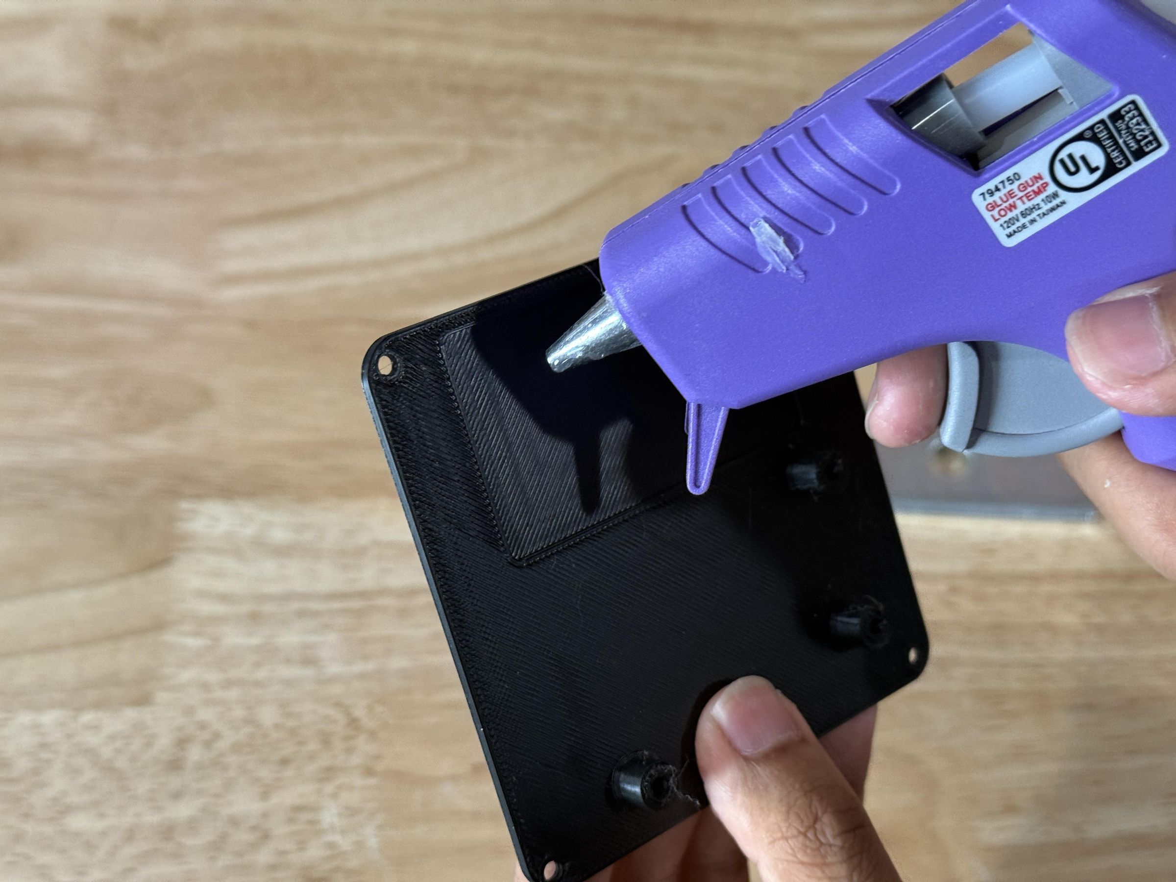
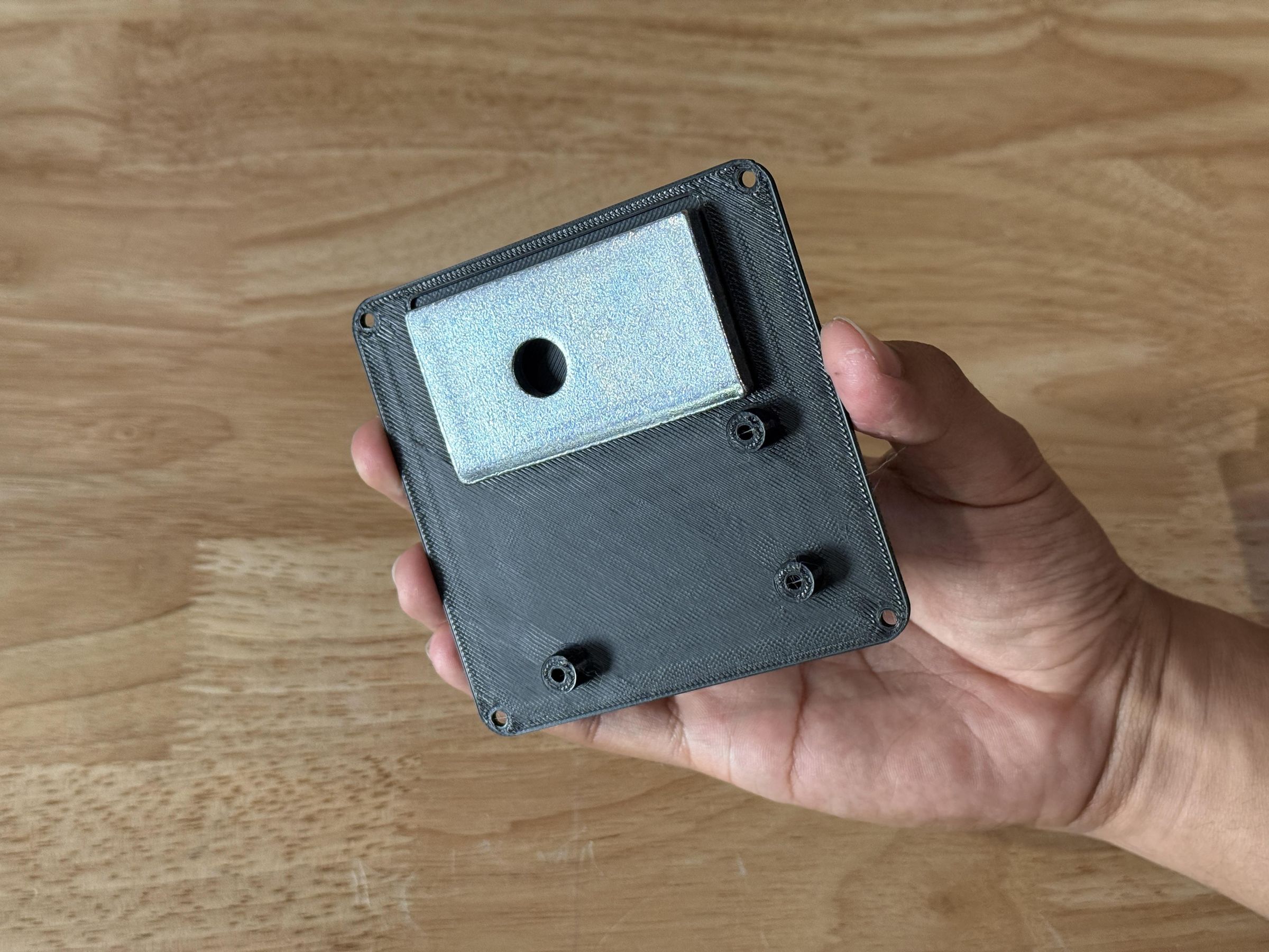
Moving to the base piece, begin aligning the metal weight with the small outline on top of the base platform. Then secure it in place using any adhesive such as hot glue.
This weight gives the fan a more premium feel and helps it stay securely on a desk while minimizing vibrations.
I also covered the top of the weight with electrical tape to prevent any issues like shorts if exposed electronics were to contact it.
Install Electronics
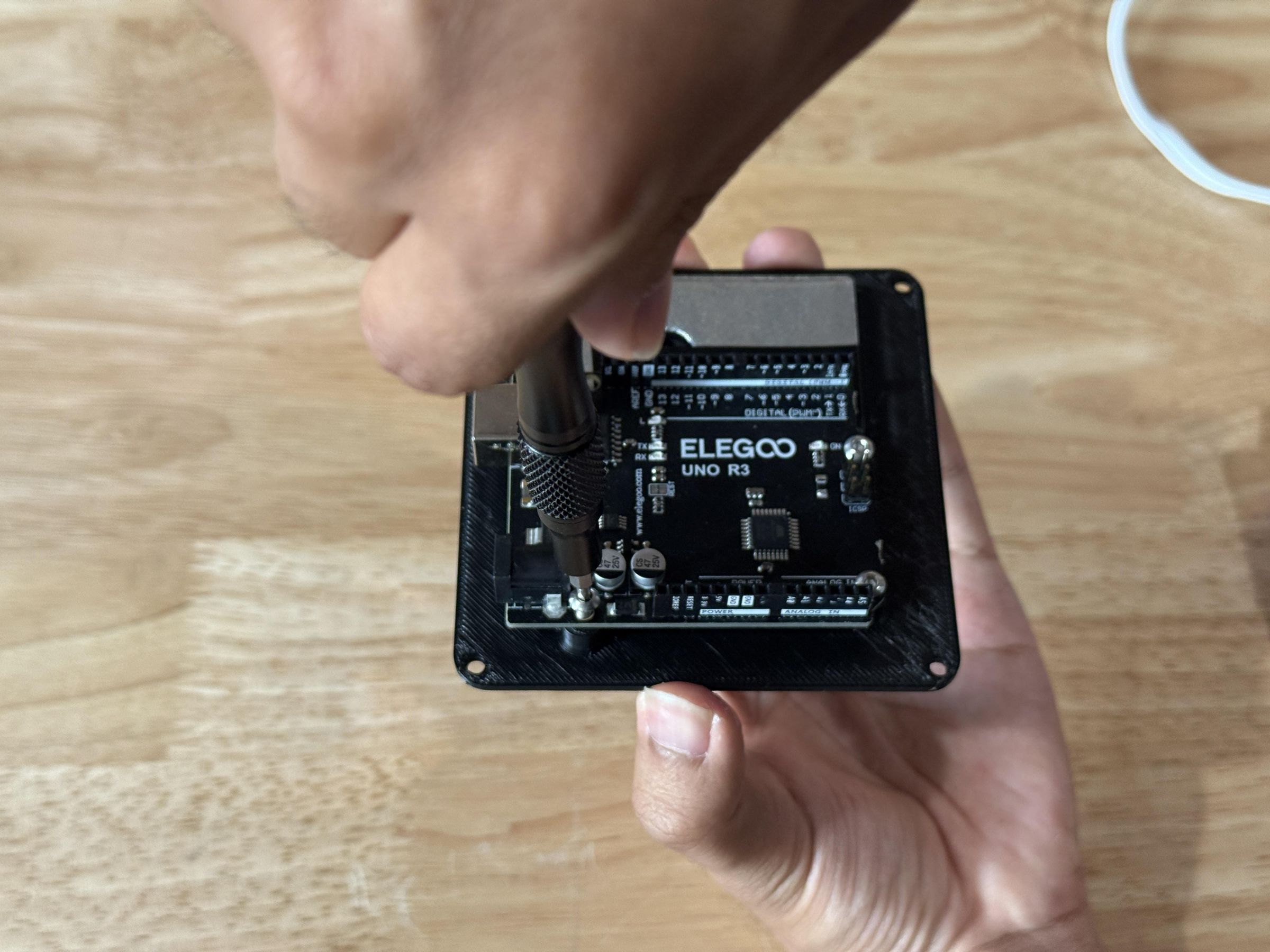
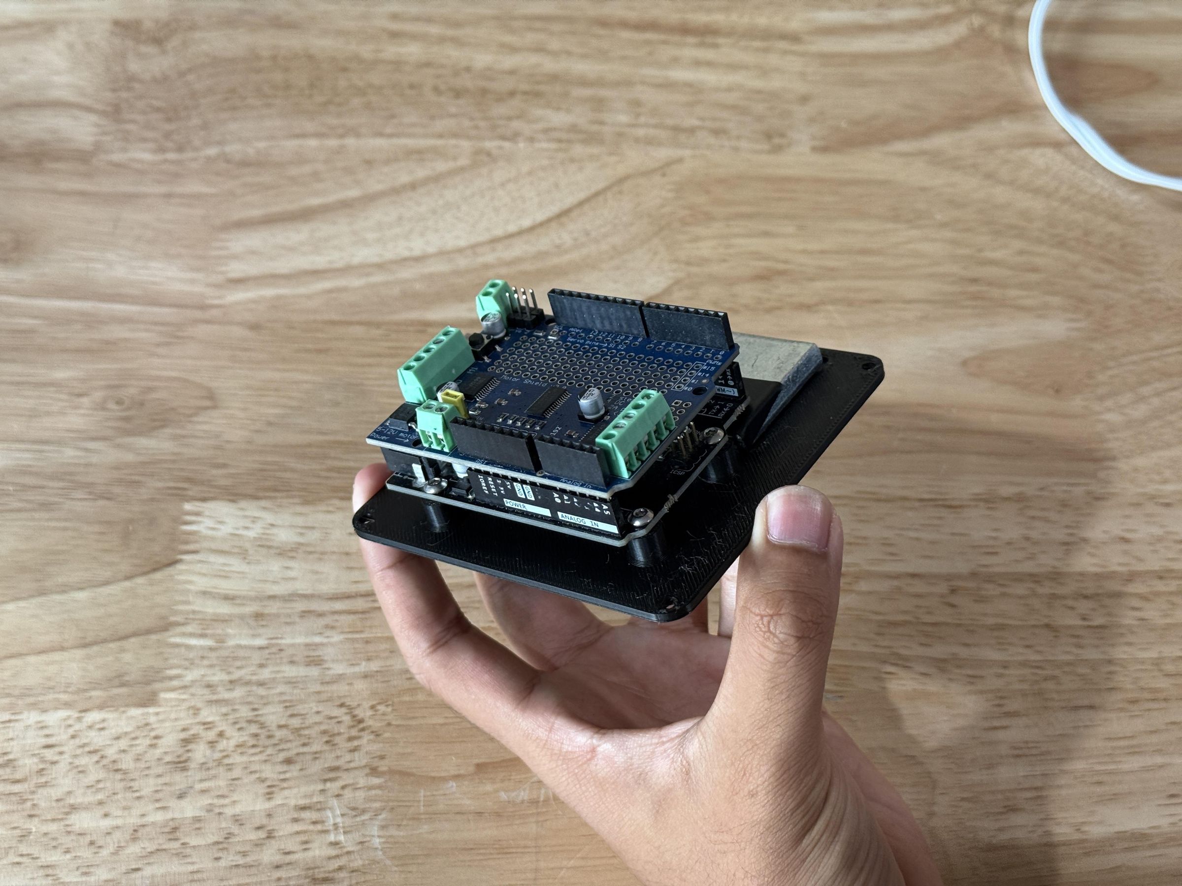
Position the mounting holes on the Arduino Uno over the three standoffs on the baseplate, then secure it with M3x8mm bolts.
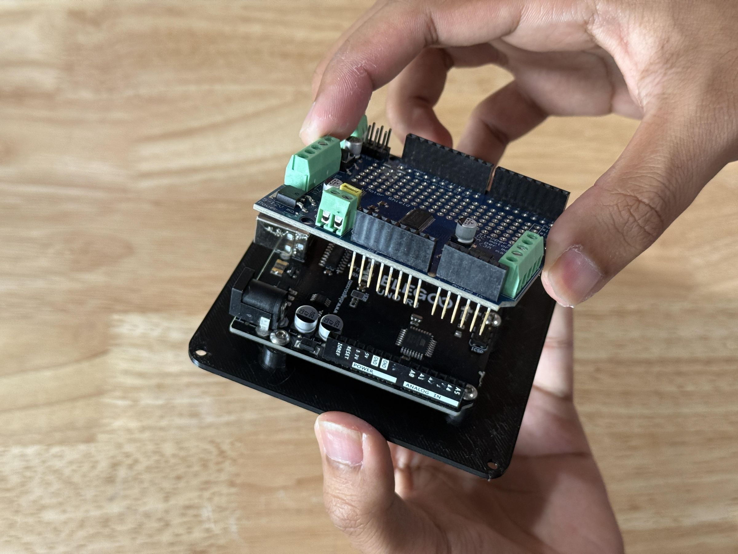
Then attach the Adafruit Motor Shield to the top of the Arduino, ensuring all the pins are positioned correctly and drop into the correct place. Press the shield down until it is fully seated and parallel with the Arduino.
Program Arduino
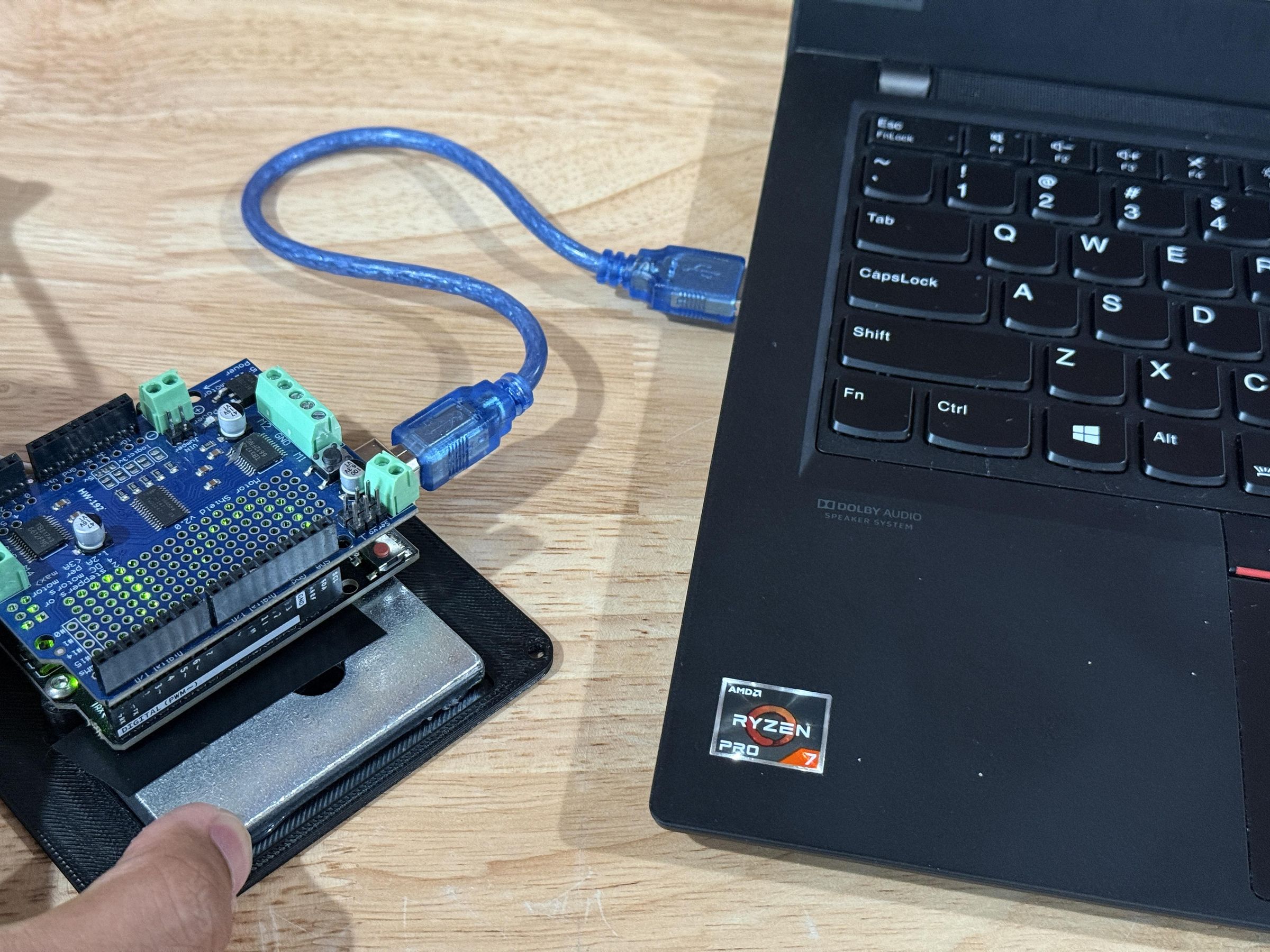
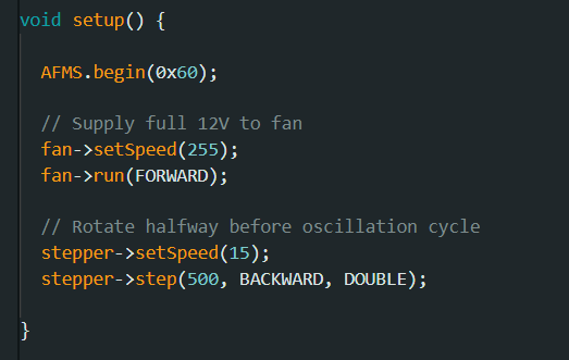
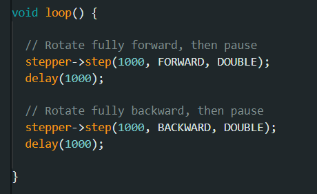
Connect the Arduino to a computer using a USB A to USB B cable. Then upload the program using the Arduino IDE software.
The first part of the code commands the fan motor to run forward at maximum speed, as the fan requires the full 12V power for efficient operation. Then it begins the oscillation cycle by turning the stepper motor halfway in one direction (500 steps).
The second section of code runs repeatedly and continues the oscillation cycle by moving the stepper motor fully in both directions, with small delays in between. The number of steps (1000) dictates how far the fan will rotate each time.
There is a bit more to the code so the Arduino sketch is provided below for anyone who may be interested.
Downloads
Prepare Stepper Wires
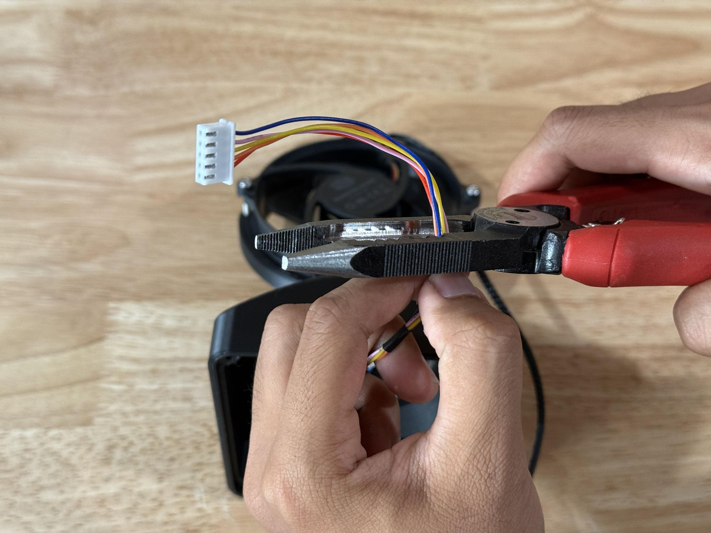
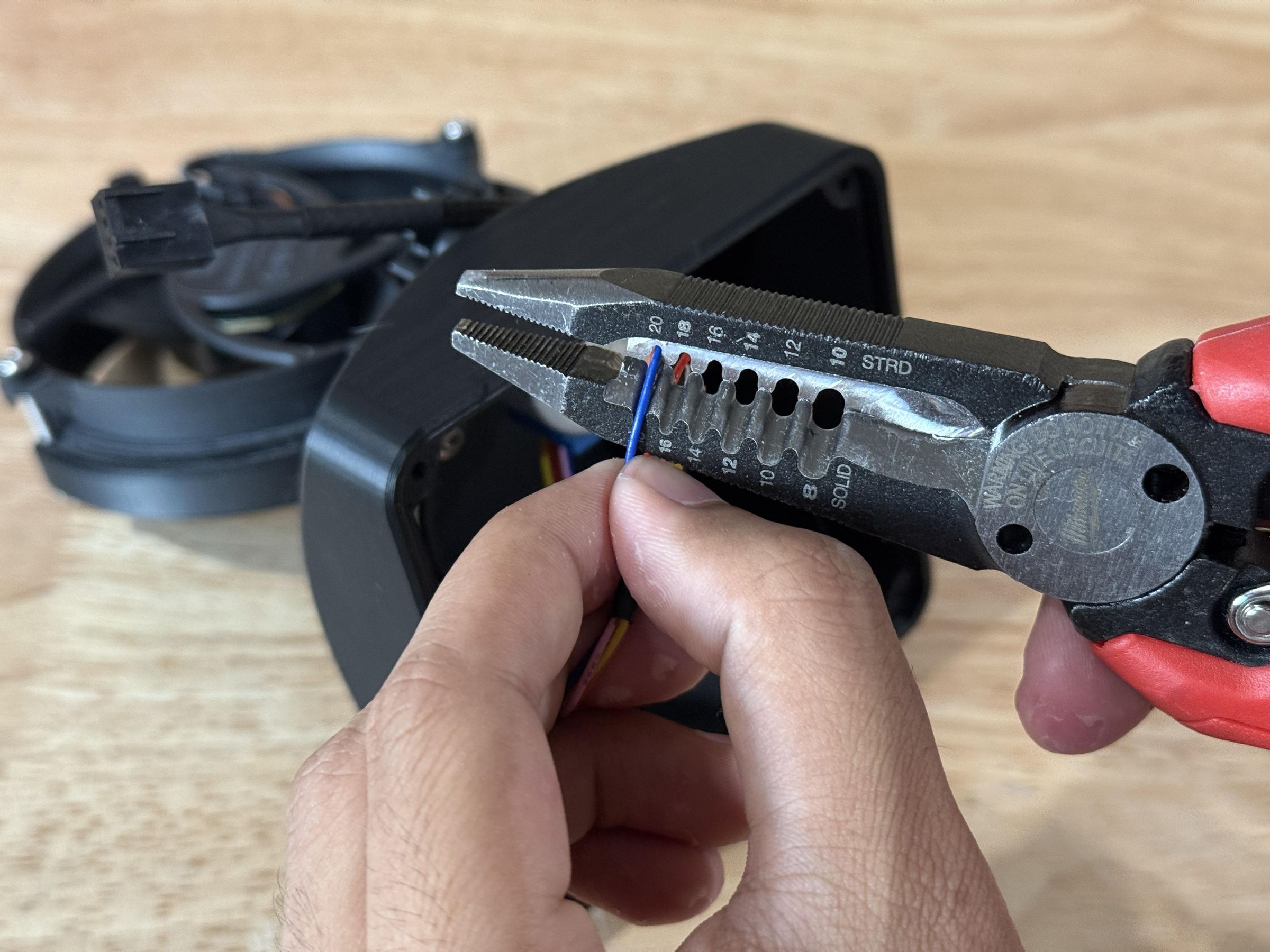
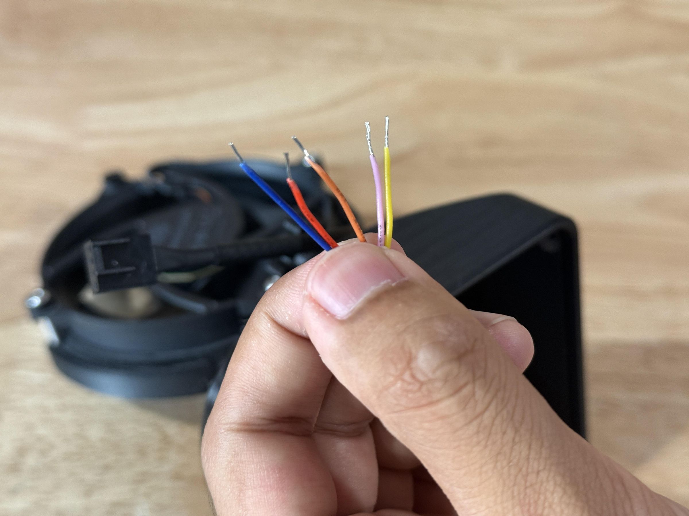
To prepare the stepper motor wires for attaching them to the motor shield, begin by cutting off the regular stepper motor connector, creating new wire ends.
Then, using a wire stripper, strip a small portion of the insolation at the end of each wire, revealing the metal underneath.
Prepare Fan Wires
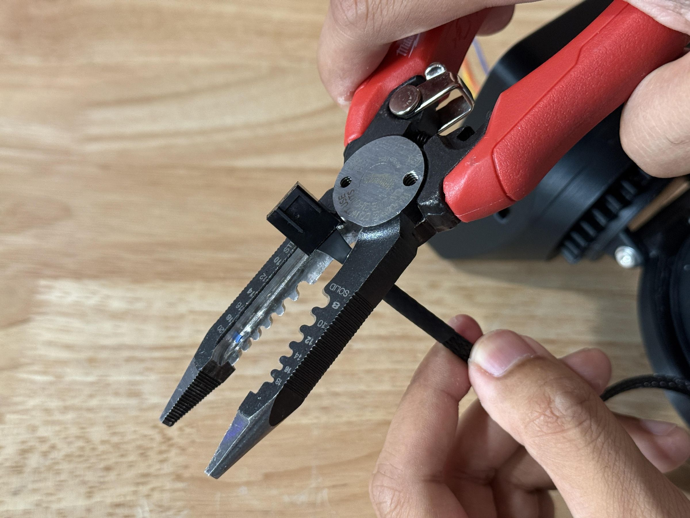
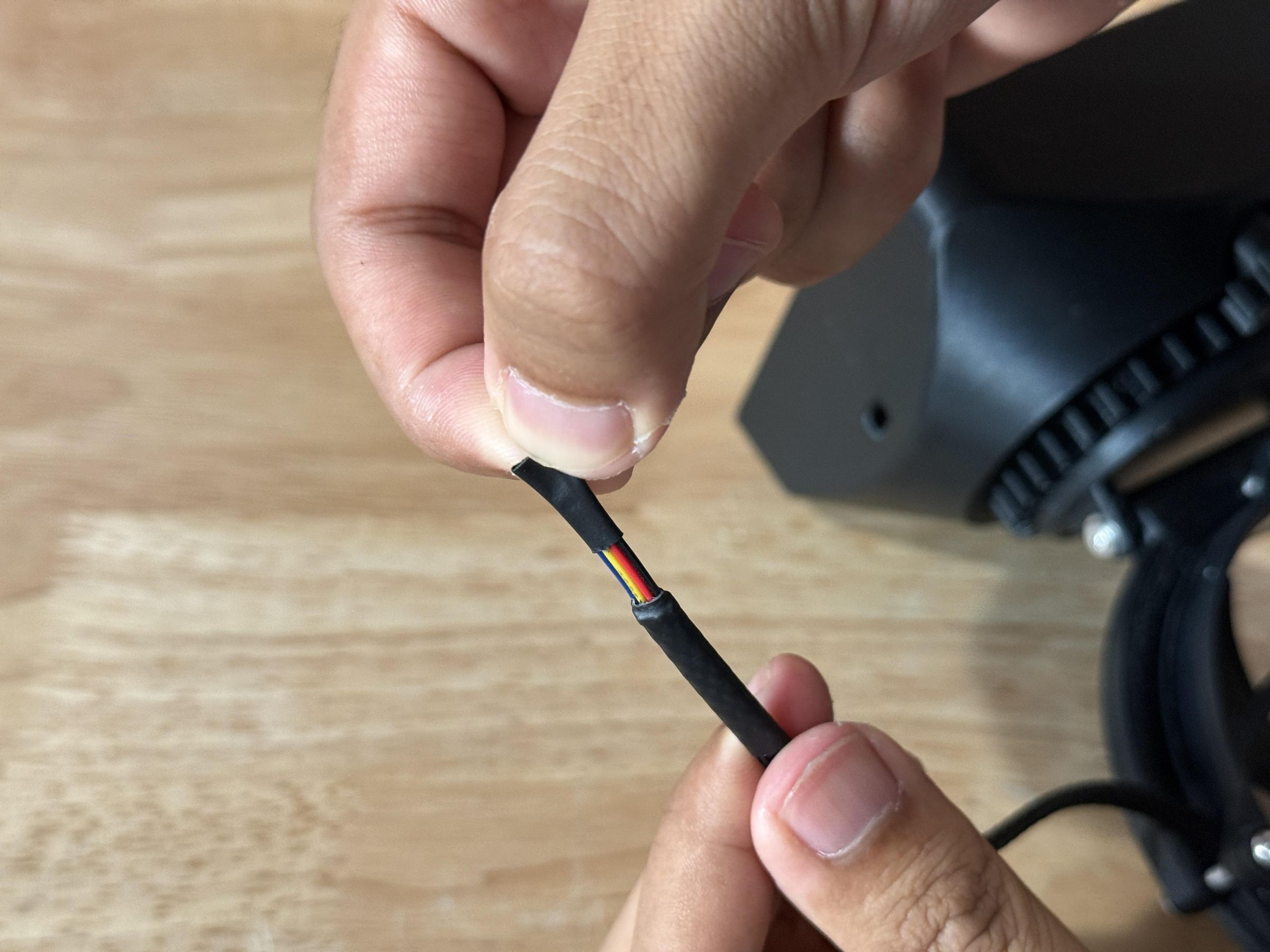
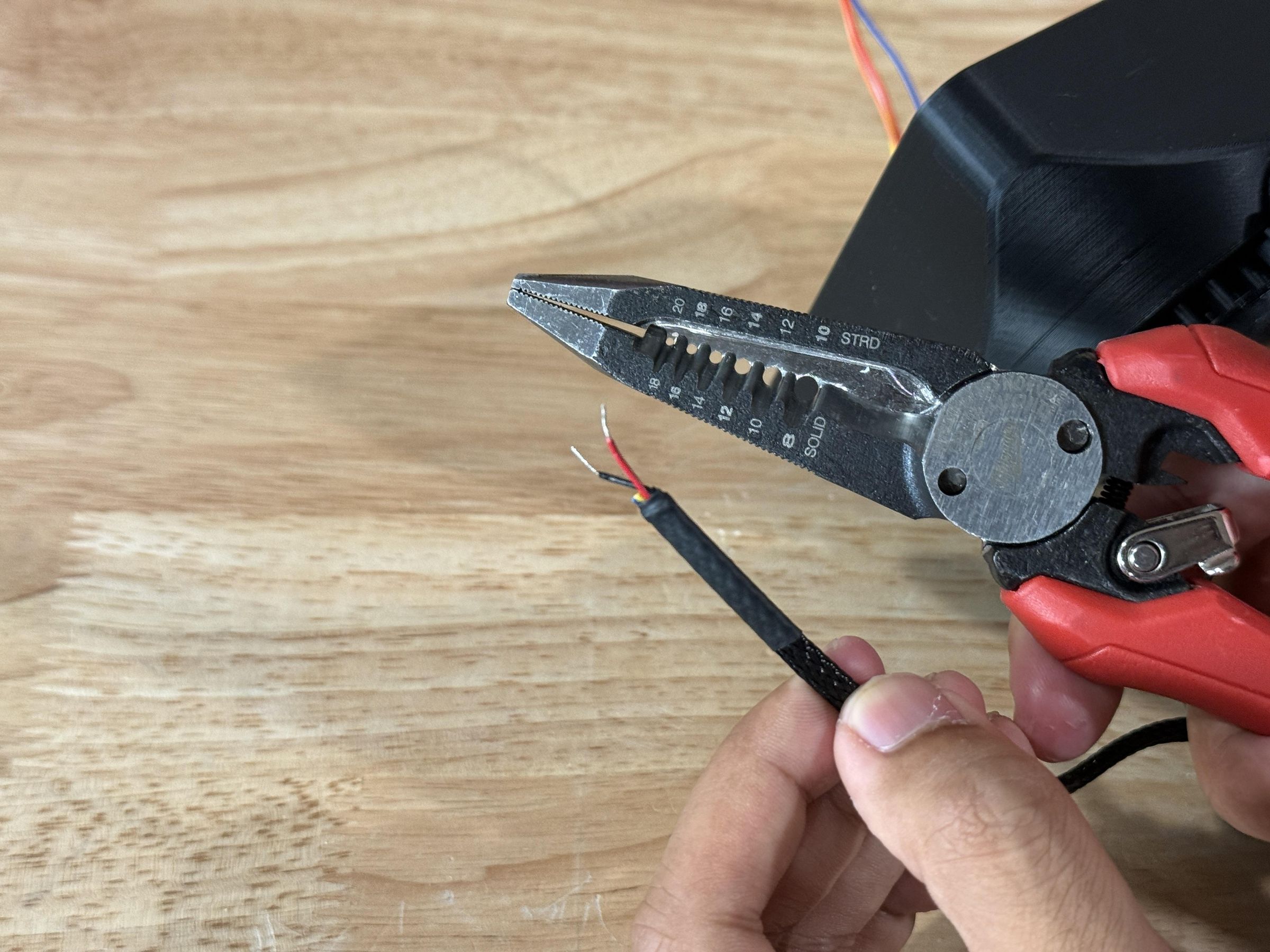
The process is similar for the fan wires, starting with severing the previous connector, and cutting part of the heat shrink tubing to reveal the colored wires inside.
There should be a blue, yellow, red, and black wire, however we only care about the red and black wires, so the blue and yellow ones can be cut or simply ignored.
Finish by stripping the red and black wires just like the stepper motor ones.
Connect Power Wires
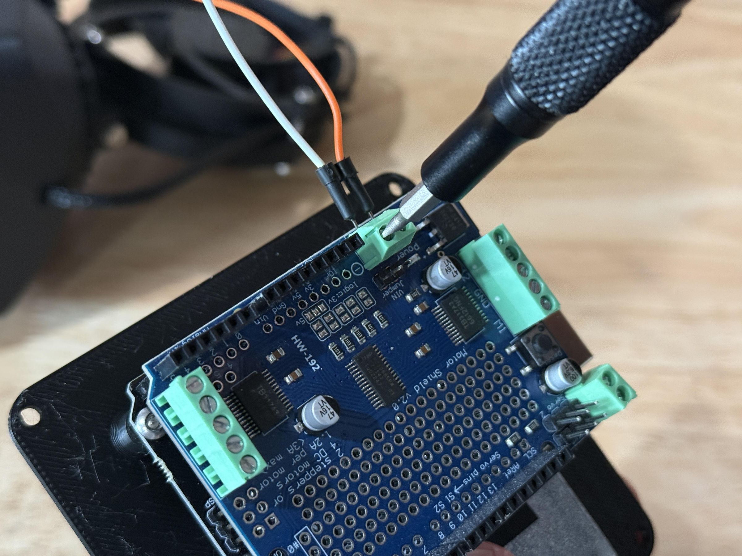
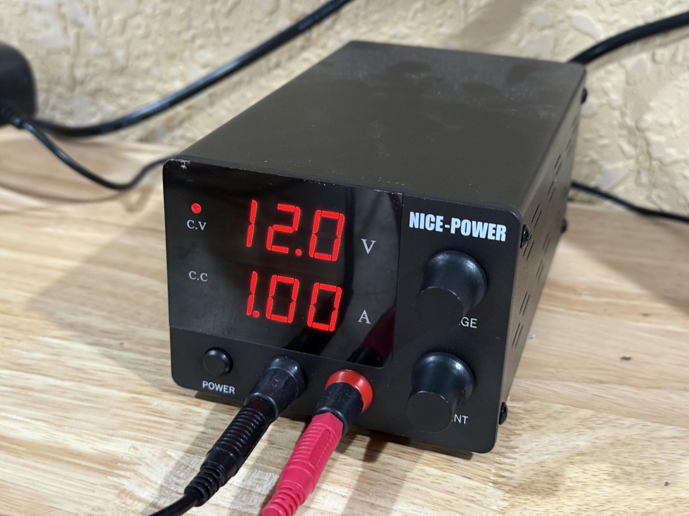
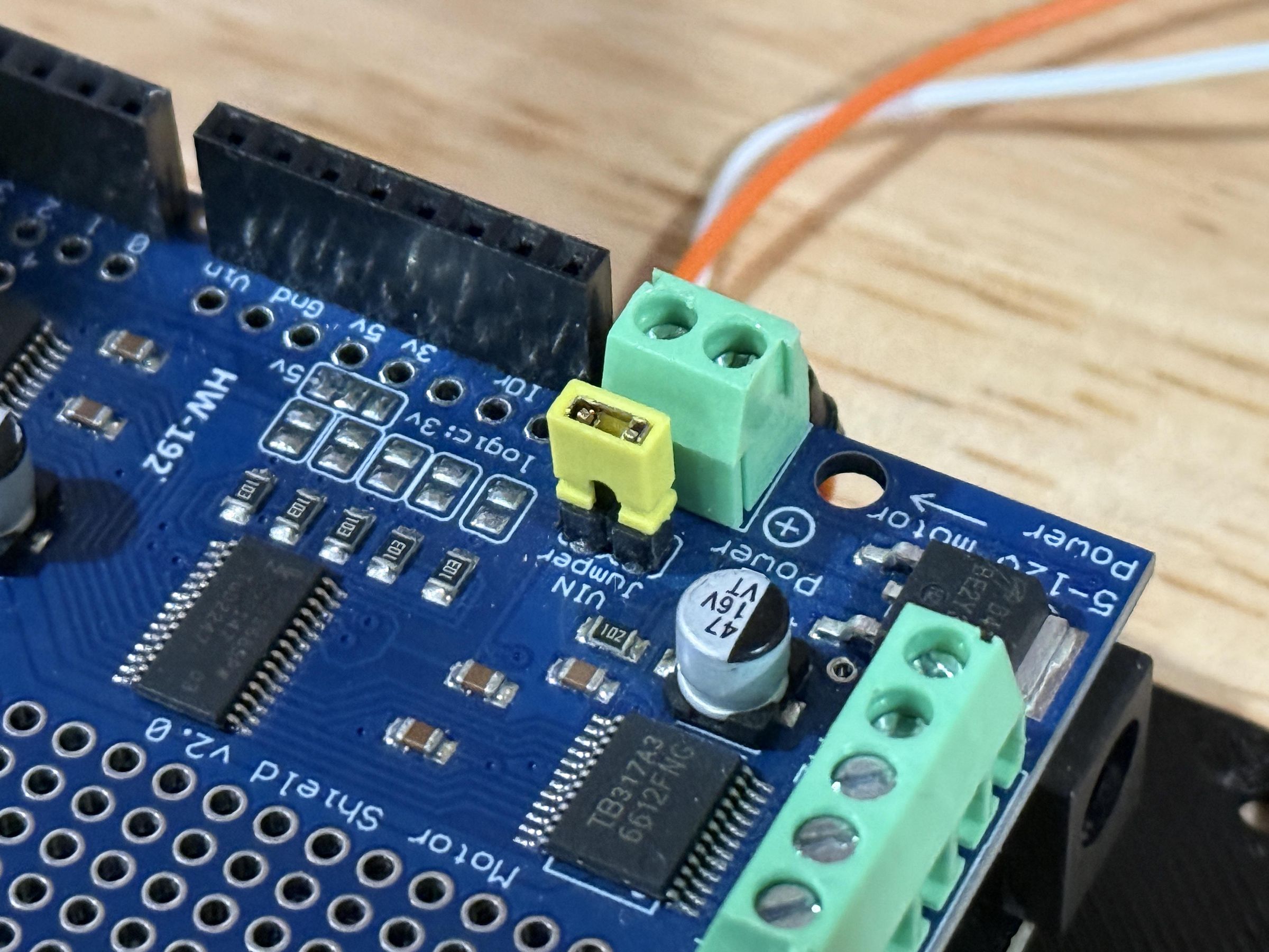
The Adafruit Motor Shield requires external power to run any motors. This power supply could be anything from a battery to an adjustable one like I am using for this project. The important aspect is that it has to be able to output 12V DC.
Connect the power supply to the motor shield using the terminals labeled "Power ->" ensuring that you follow the + and - markings on the board. Use the flathead screws to secure the power wires in place, and check that it is functioning by turning on the power and looking for a red LED.
IMPORTANT: Before inserting the electronics into the shell, ensure that the yellow jumper pin in the last image is present. This allows the Arduino to run from the same external power instead of via the computer over USB.
Finish Wiring
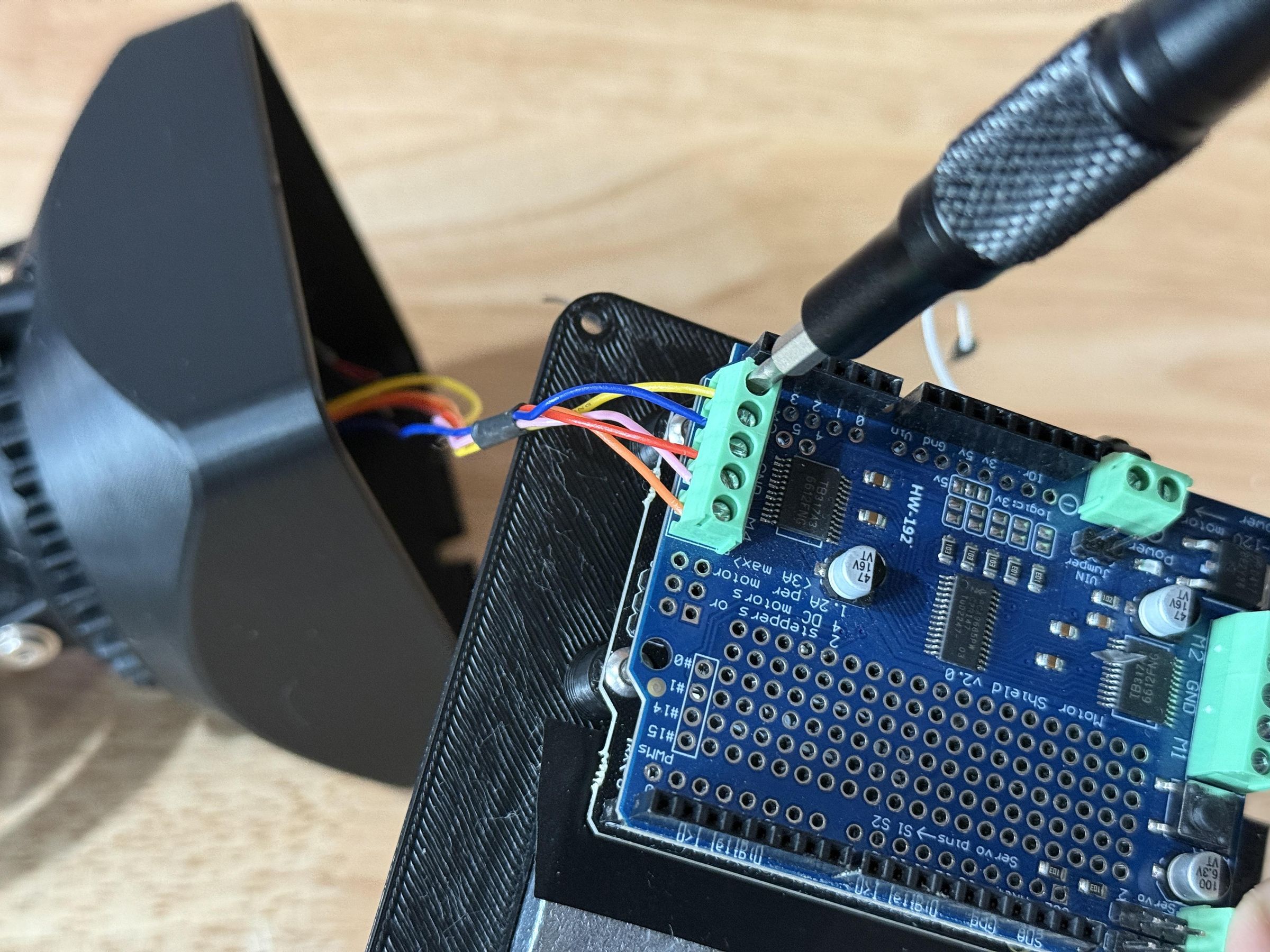
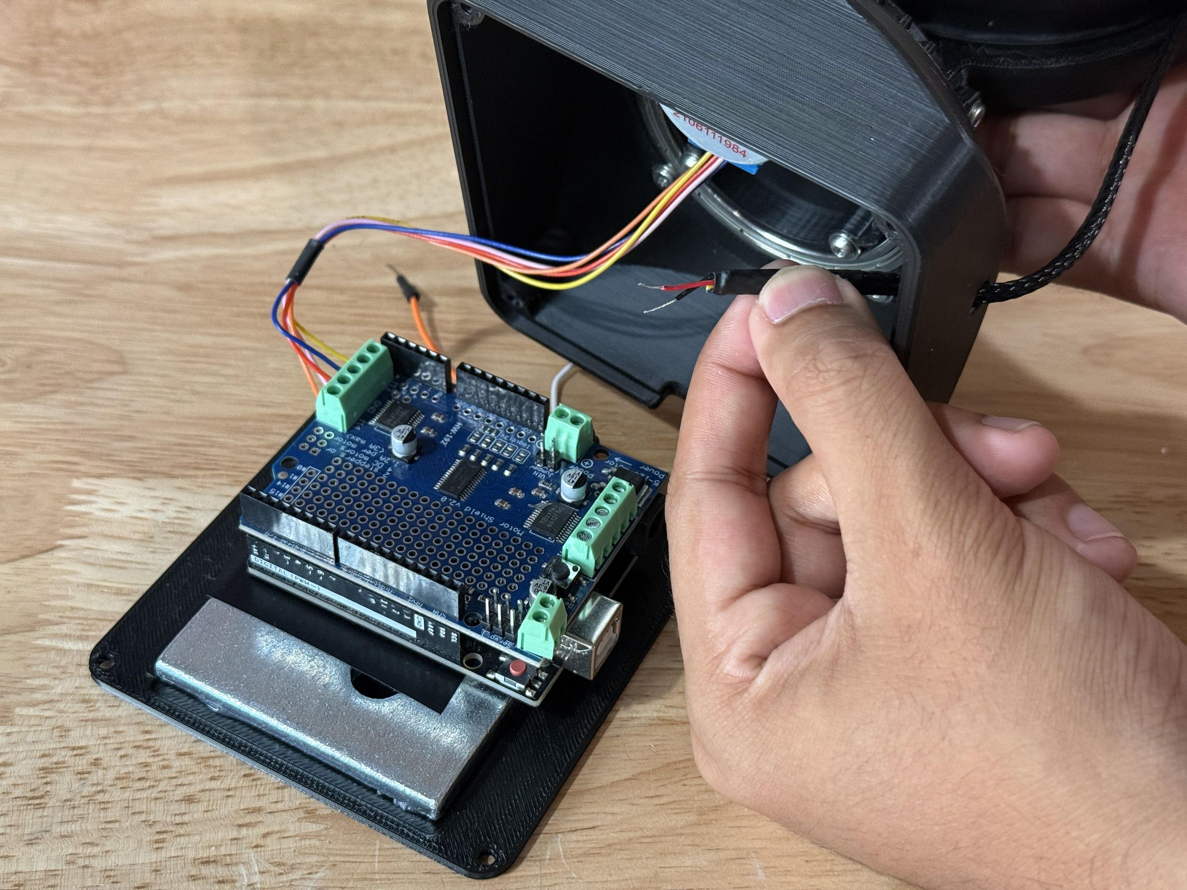
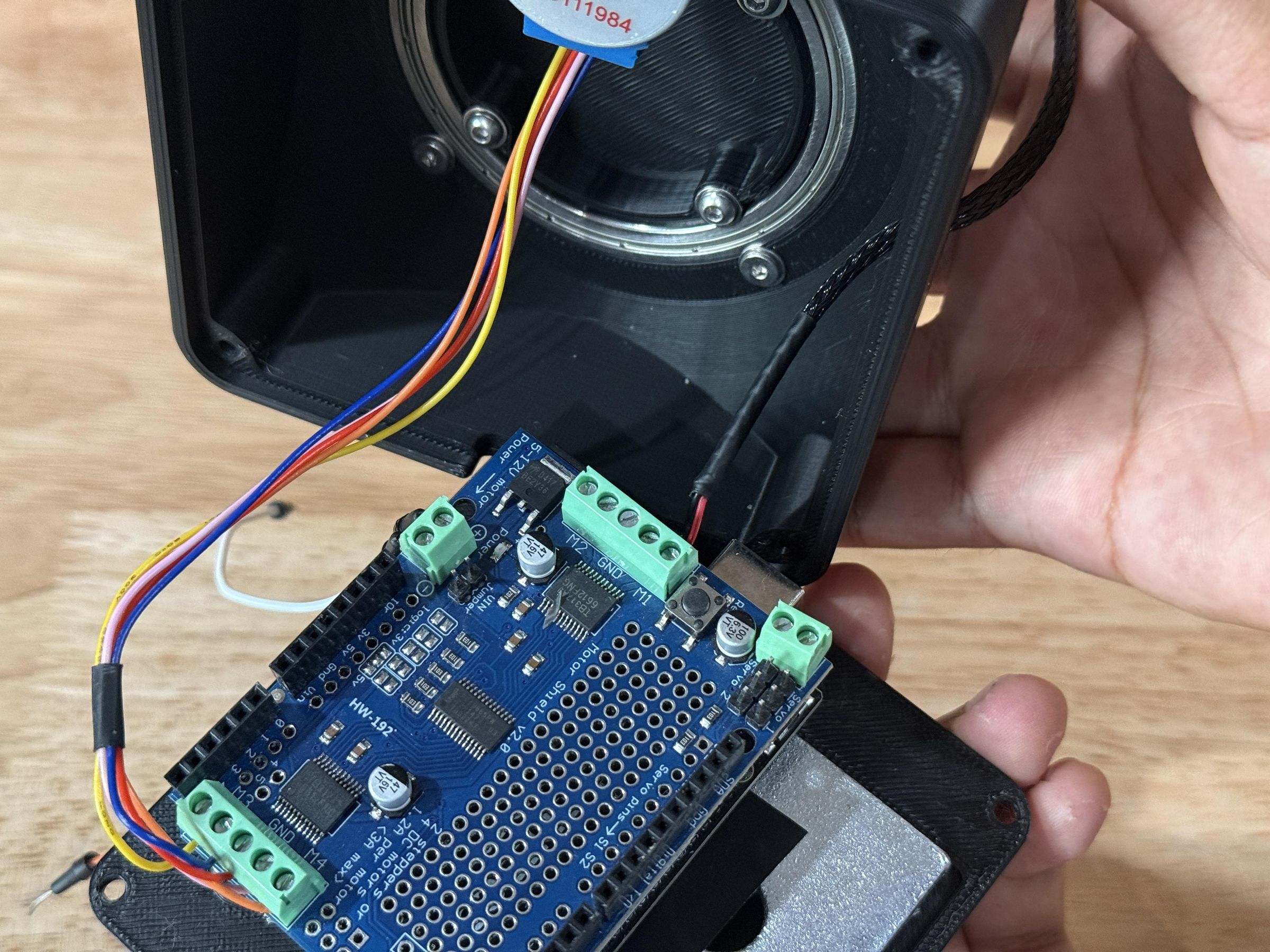
Connect the stepper motor by inserting the wires into the terminal side labeled M3 and M4, then tightening the screws to lock on to the exposed wire. When attaching the stepper wires, ensure they follow the color order:
Orange -> Pink -> Red -> Blue -> Yellow
Feed the fan wires through the hole in the side of the shell and direct them toward the terminal blocks on the other side of the motor shield. Then connect the wires to the terminal pair labeled M1, with the black wire being closest to the middle, and the red wire being on the outside.
Connect Base
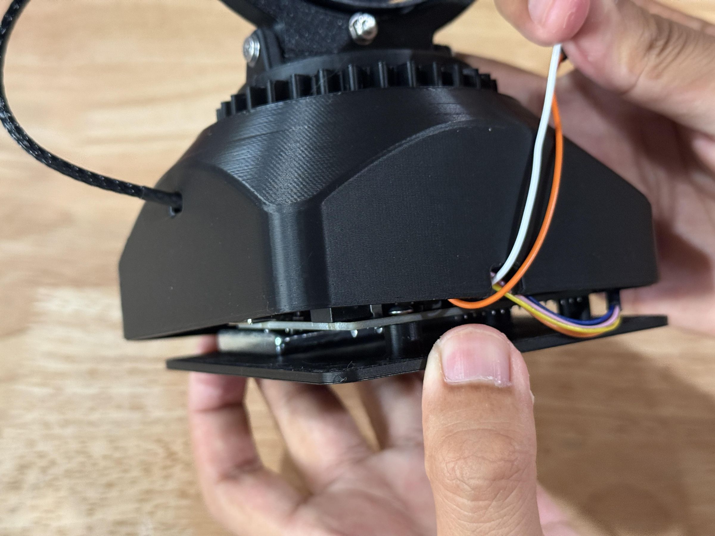
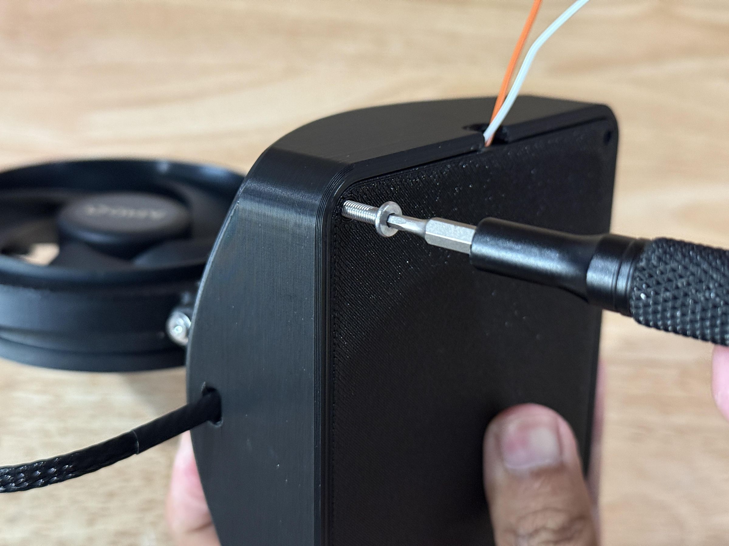
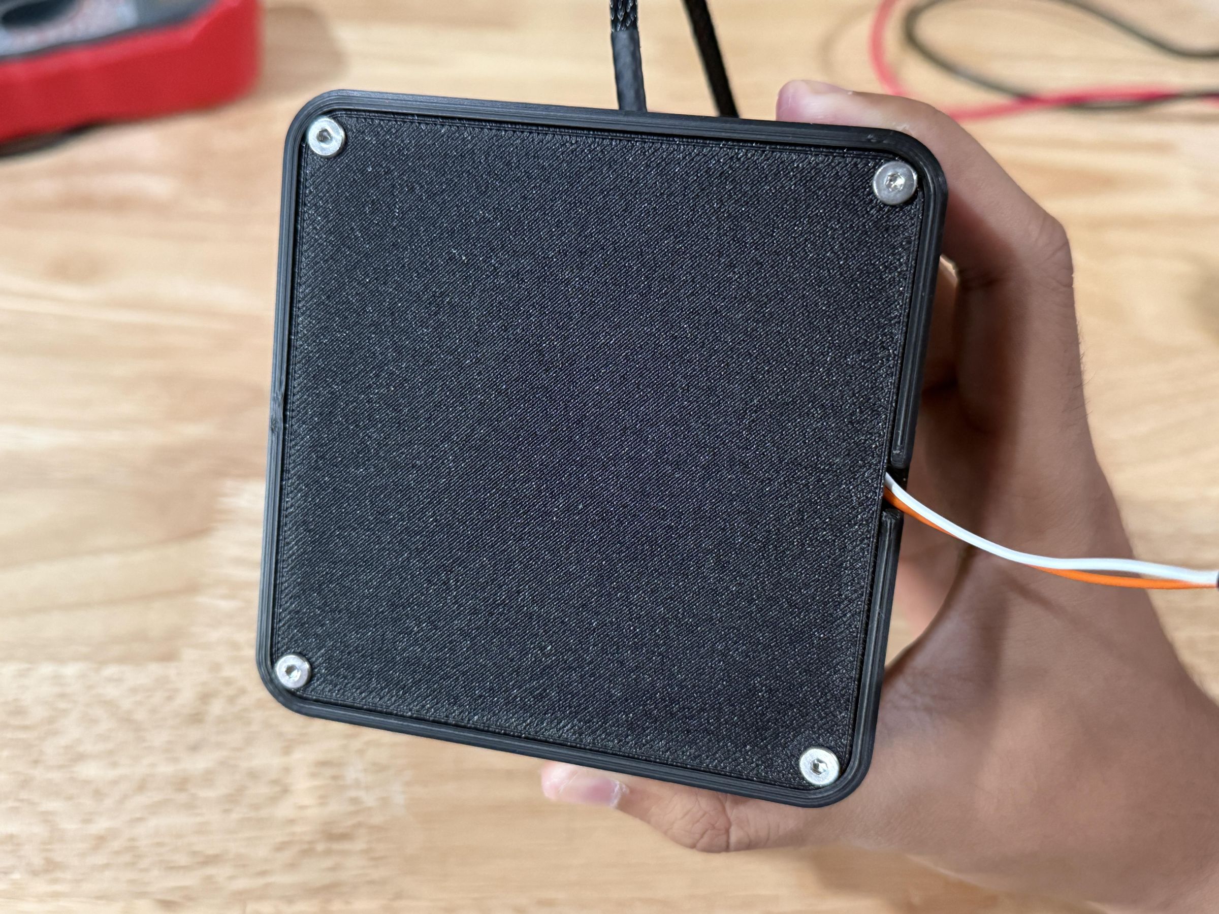
Finally, push the base up into the shell, ensuring that it is in the correct orientation (Weight should be at front) and that any wires are pushed inside. This is with the exception of the power wires, which need to be directed through the slot at the back of the shell, allowing the base to sit recessed into the shell.
To secure the base, use four M3x14mm bolts on the bottom corners which thread into the underside of the shell and complete the fan build.
Test!
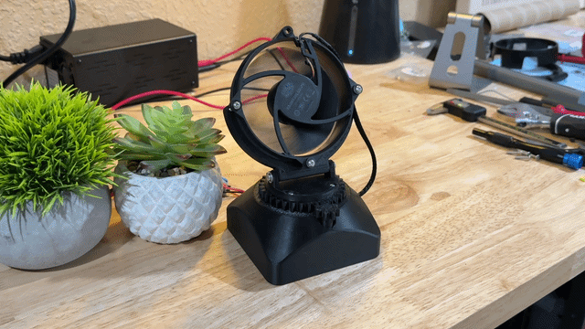
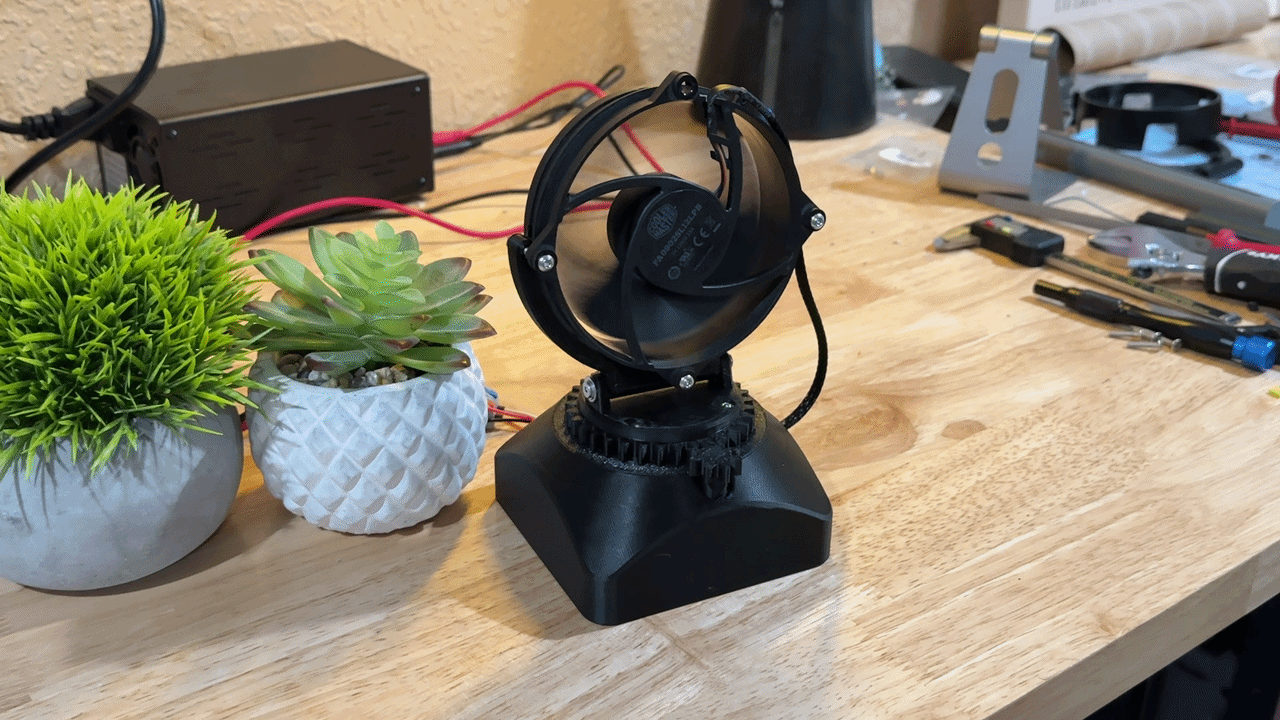
Supplying 12V DC power should spin up the CPU fan and begin the stepper motor's oscillation cycle. Check that the fan is outputting ample airflow and the gears are spinning the correct distance.
You can also experiment with different fan tilt angles, but most importantly enjoy the cool breeze.
Conclusion
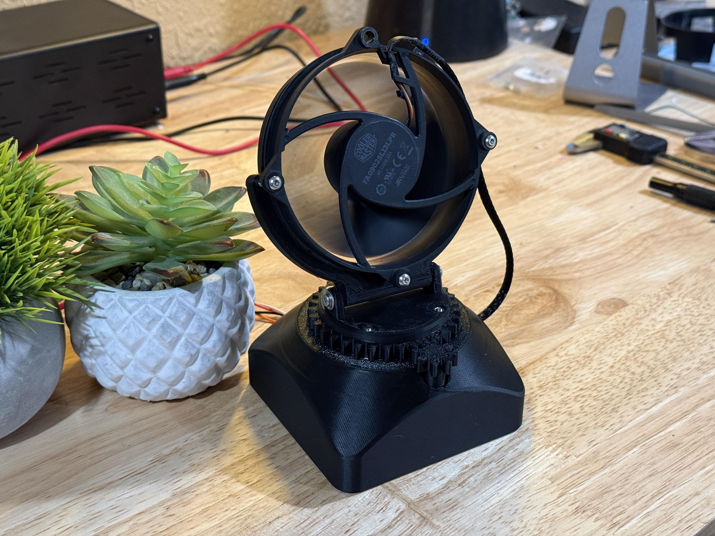
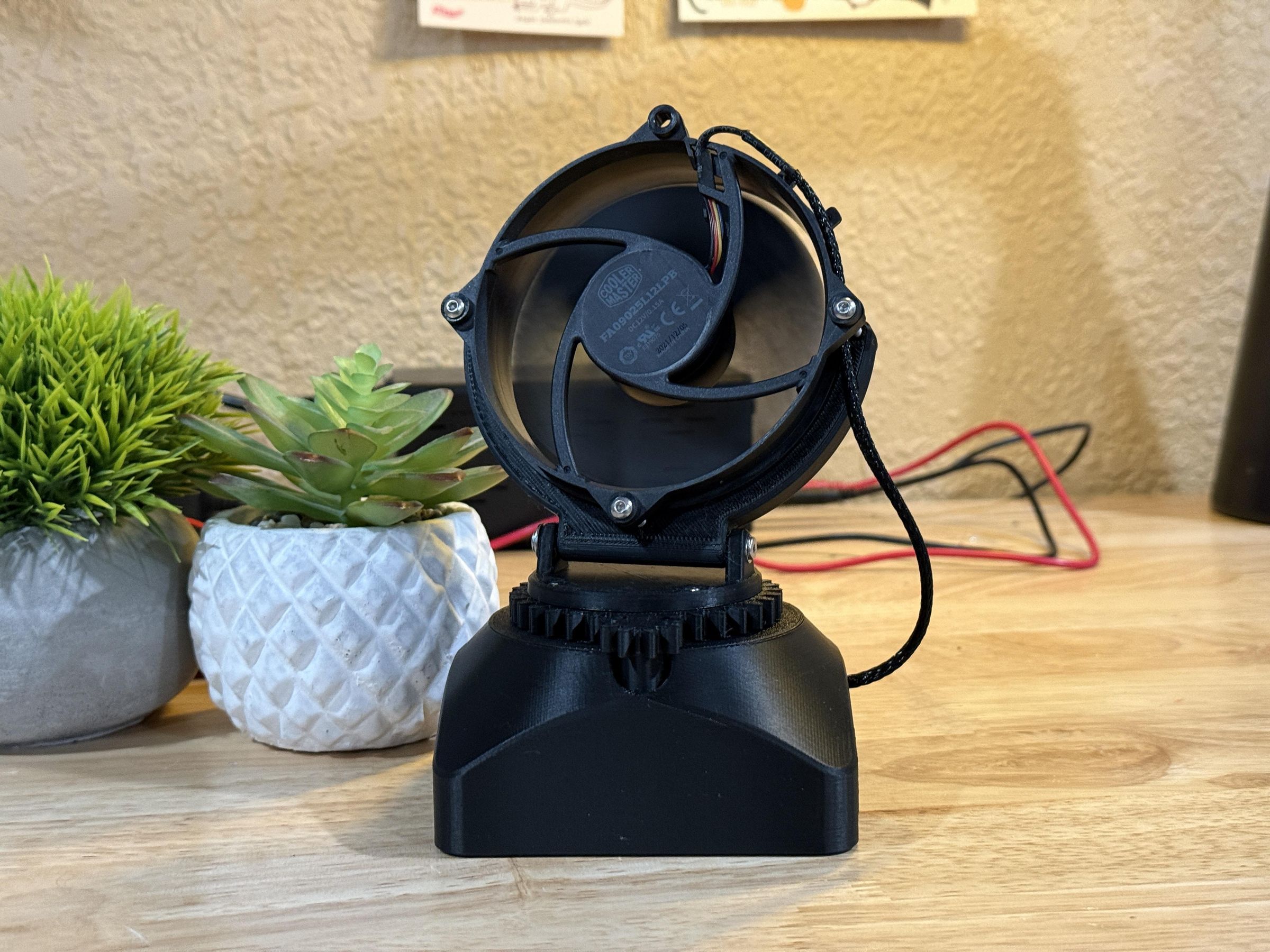
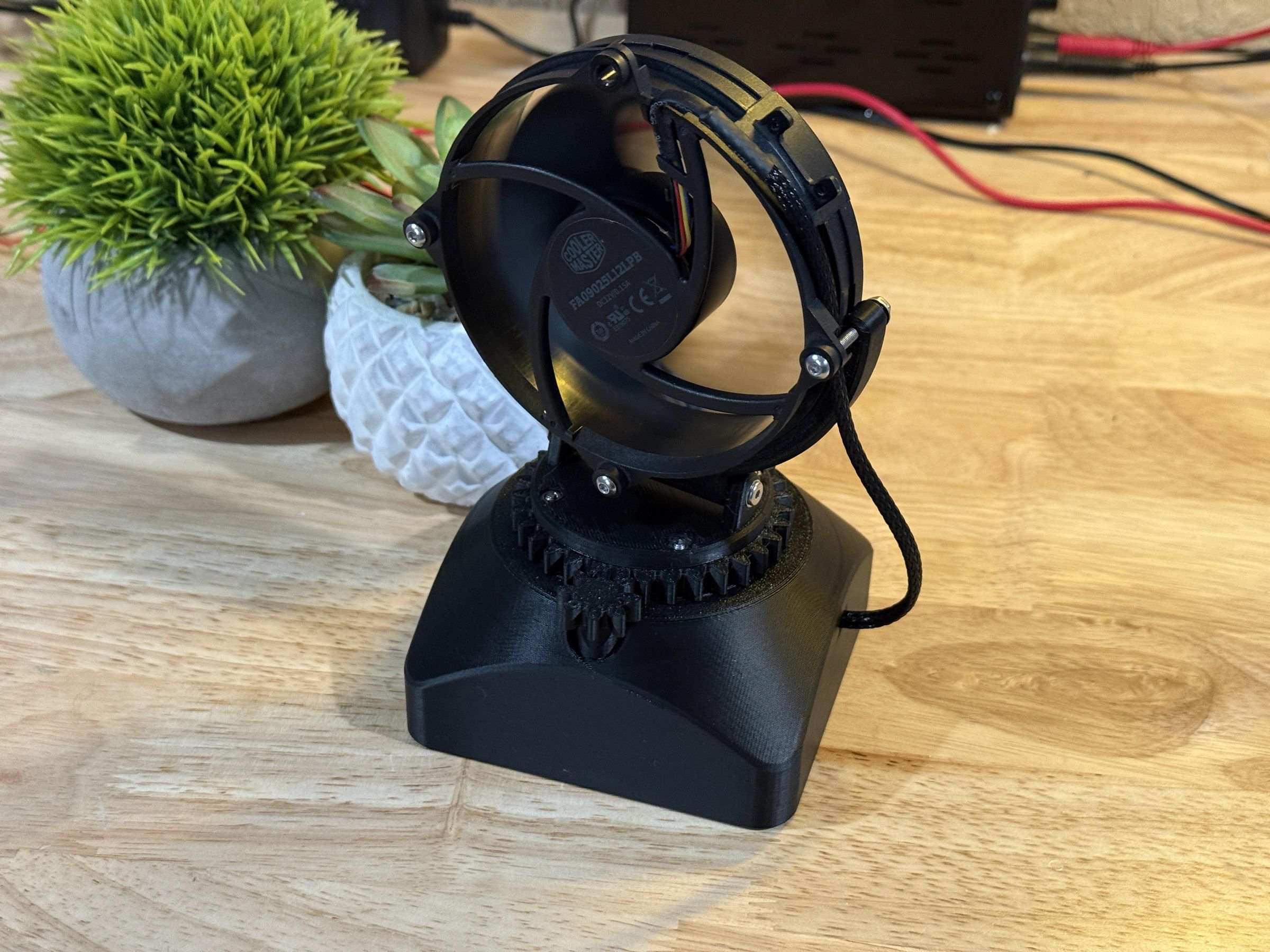
This project was a good example of how unused electronics can be utilized to create a product that makes life easier or more comfortable. The CPU cooler was actually designed to cool stuff, and this project redirects that ability into a user focused product.
Whether you are looking for an electronics project, have a spare CPU cooler around, or are just looking for some relief from the hot weather, I hope this Instructable was helpful.