PCRGo: a Battery-Powered PCR Machine for DNA Amplification
by smithcs in Circuits > Microcontrollers
983 Views, 14 Favorites, 0 Comments
PCRGo: a Battery-Powered PCR Machine for DNA Amplification

UPDATE: 29th July 2026
PCRGo goes to Brazil!
The free PCRGo is going to Brazil! The State University of Feira de Santana (UEFS) in Brazil and the Molecular Microbiology Lab (LAMASP), through the "BioMol Without Borders" initiative, brings molecular biology to public schools (K-12) using environmental DNA (eDNA), DNA barcoding, and water quality monitoring. Their mission is to make biotechnology accessible and inspire the next generation of scientists. I look forward to seeing what they can do with the PCRGo!!!
What is PCRGo!
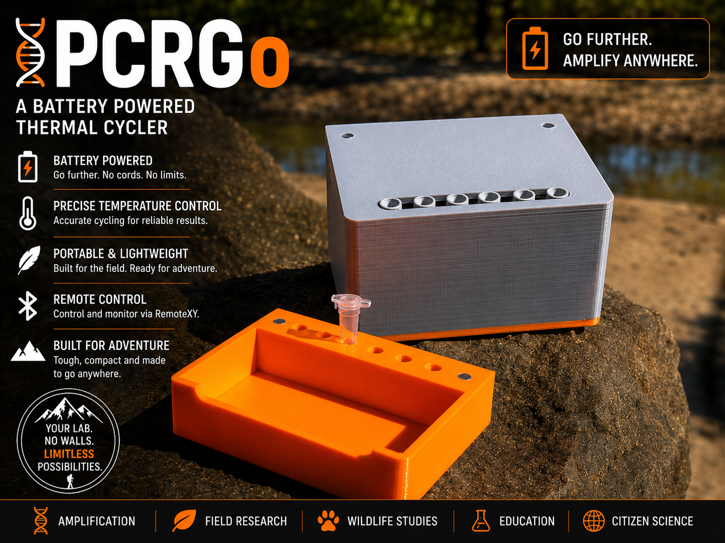
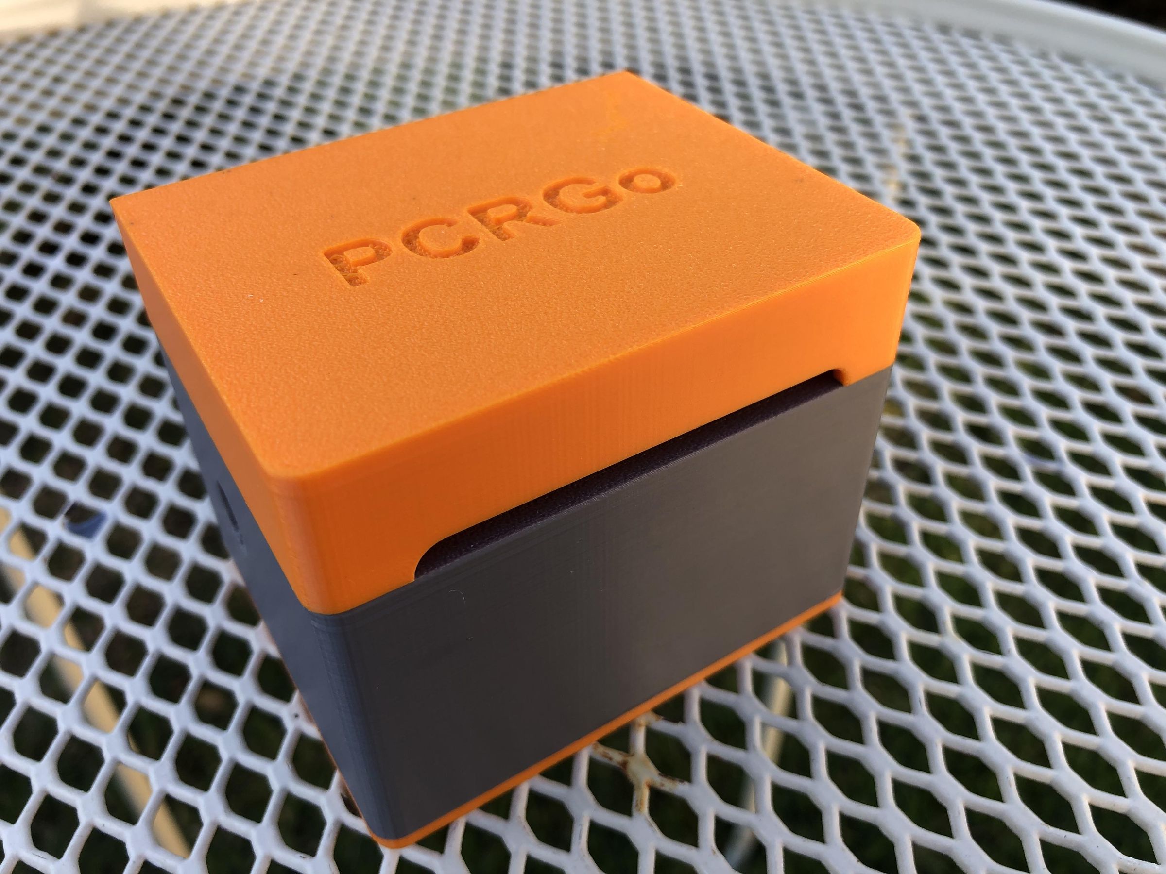
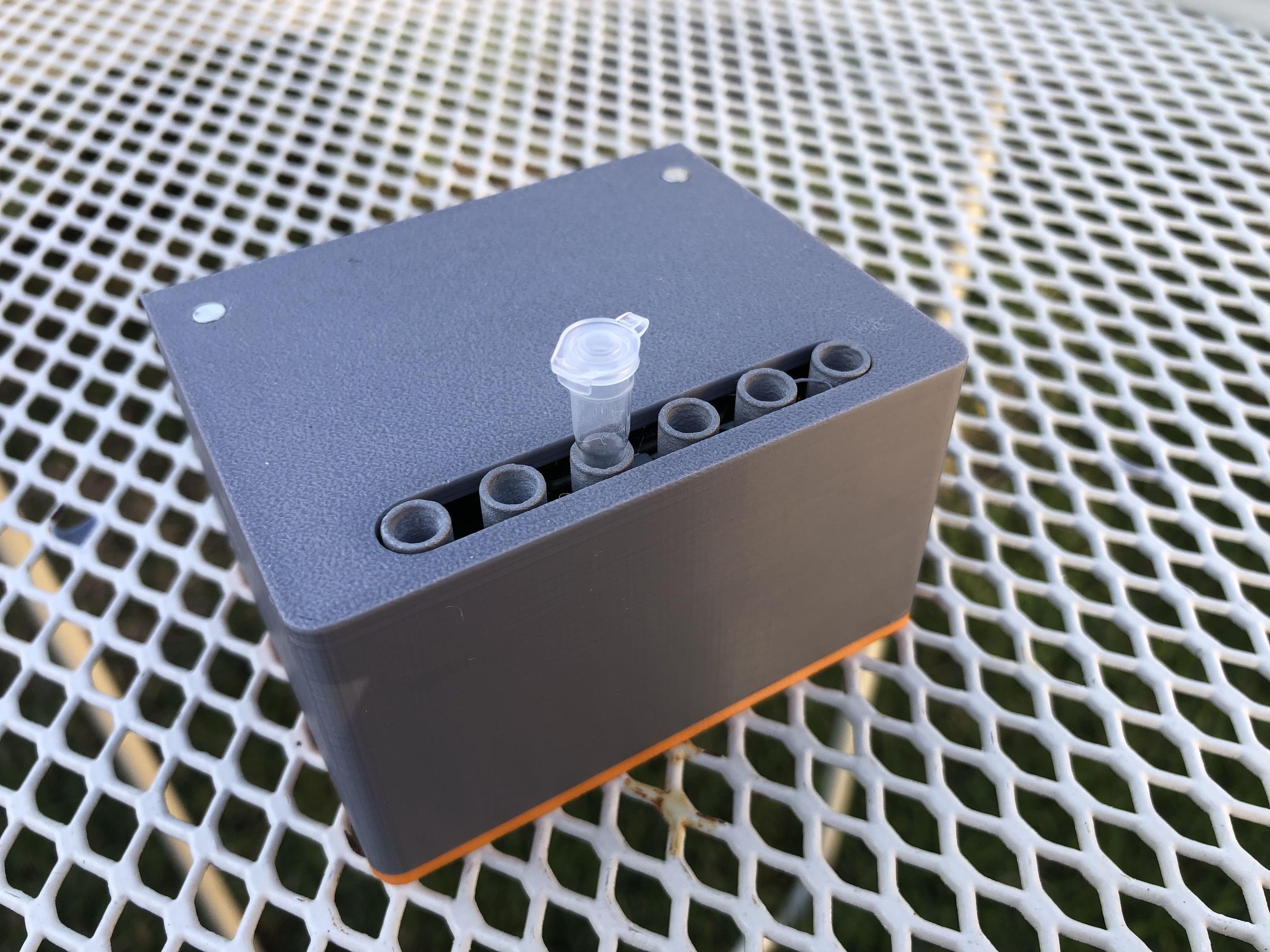
PCRGo is a battery-powered PCR machine, or thermal cycler, for DNA amplification. It is wirelessly controlled using your device and the app RemoteXY.
Powered by two replaceable 18650 lithium-ion batteries and built from affordable, readily available components, PCRGo brings PCR technology beyond the laboratory and into classrooms, research settings, and remote field locations, making genetic testing more accessible than ever before and placing the power of a molecular biology laboratory in the palm of your hand.
UPDATE: 11th July 2026
Pick and Place PCB
The design of the pick-and-place PCB is now complete! Instead of spending hours soldering tiny electronic components by hand, the board will arrive from the manufacturer fully assembled and populated with all of the surface-mount components. This makes building PCRGo much faster, easier, and more reliable.
The updated PCB design also incorporates several hardware improvements, including upgraded Schottky diodes, more capable MOSFETs, and pull-down resistors to improve circuit reliability during start-up. A DC barrel jack has also been added, allowing the batteries to be conveniently recharged through the onboard Battery Management System (BMS) without needing to remove them from the enclosure.
These files will be available soon!
UPDATE: 5th July 2026
Mangrove ecology with PCRGo
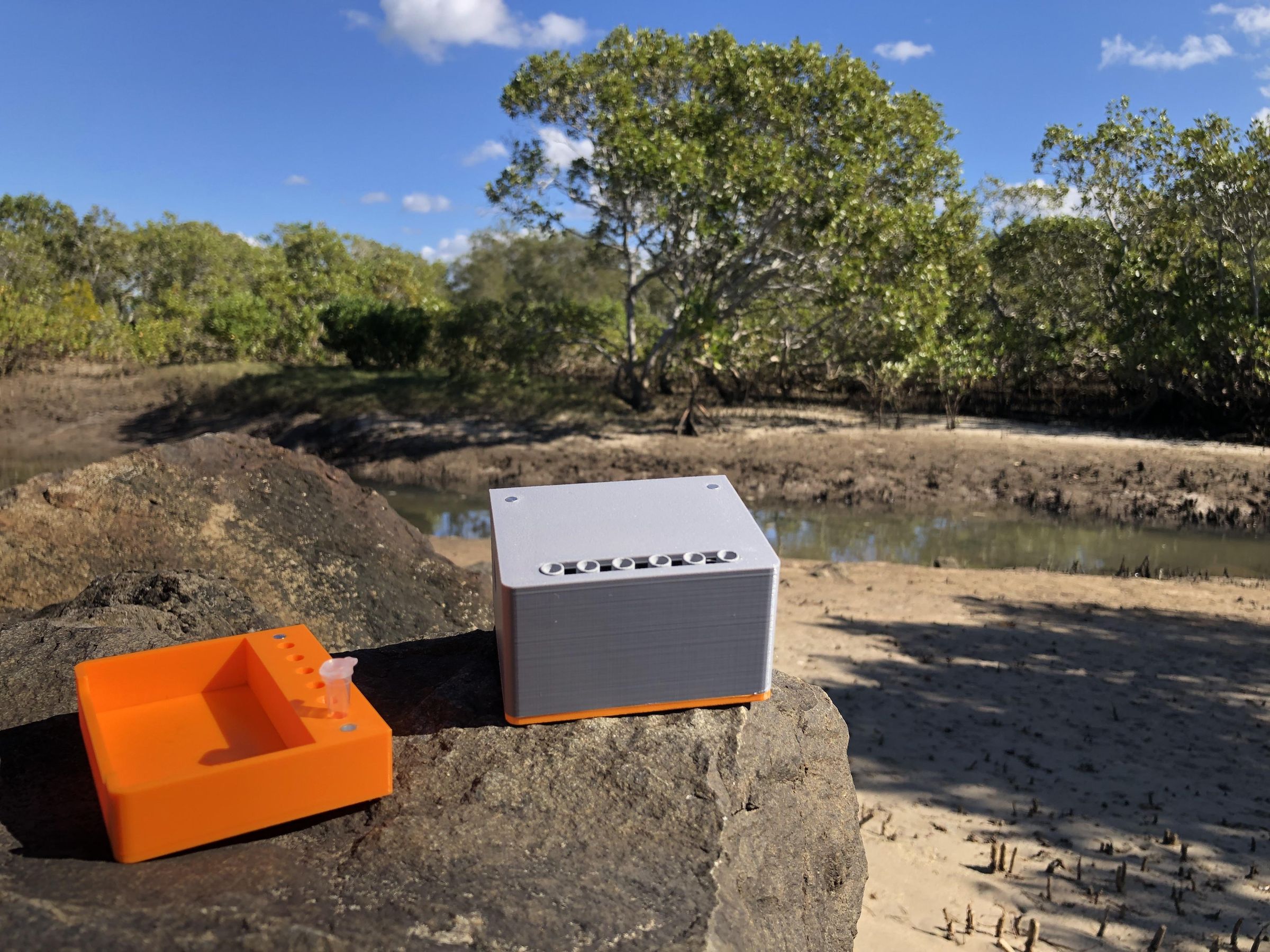
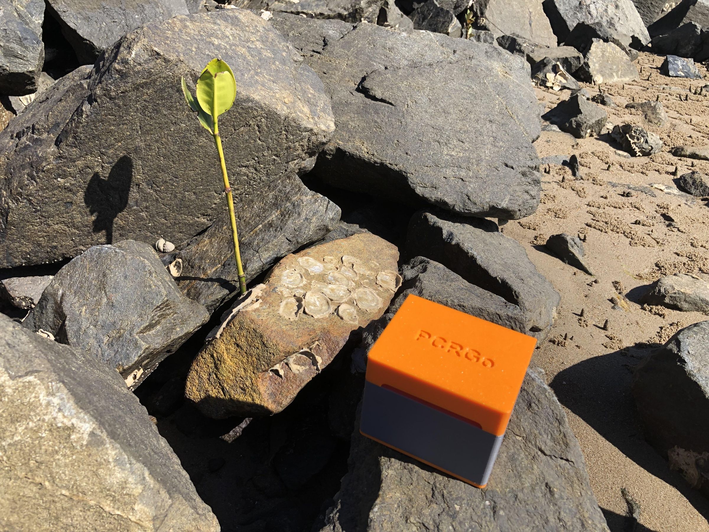
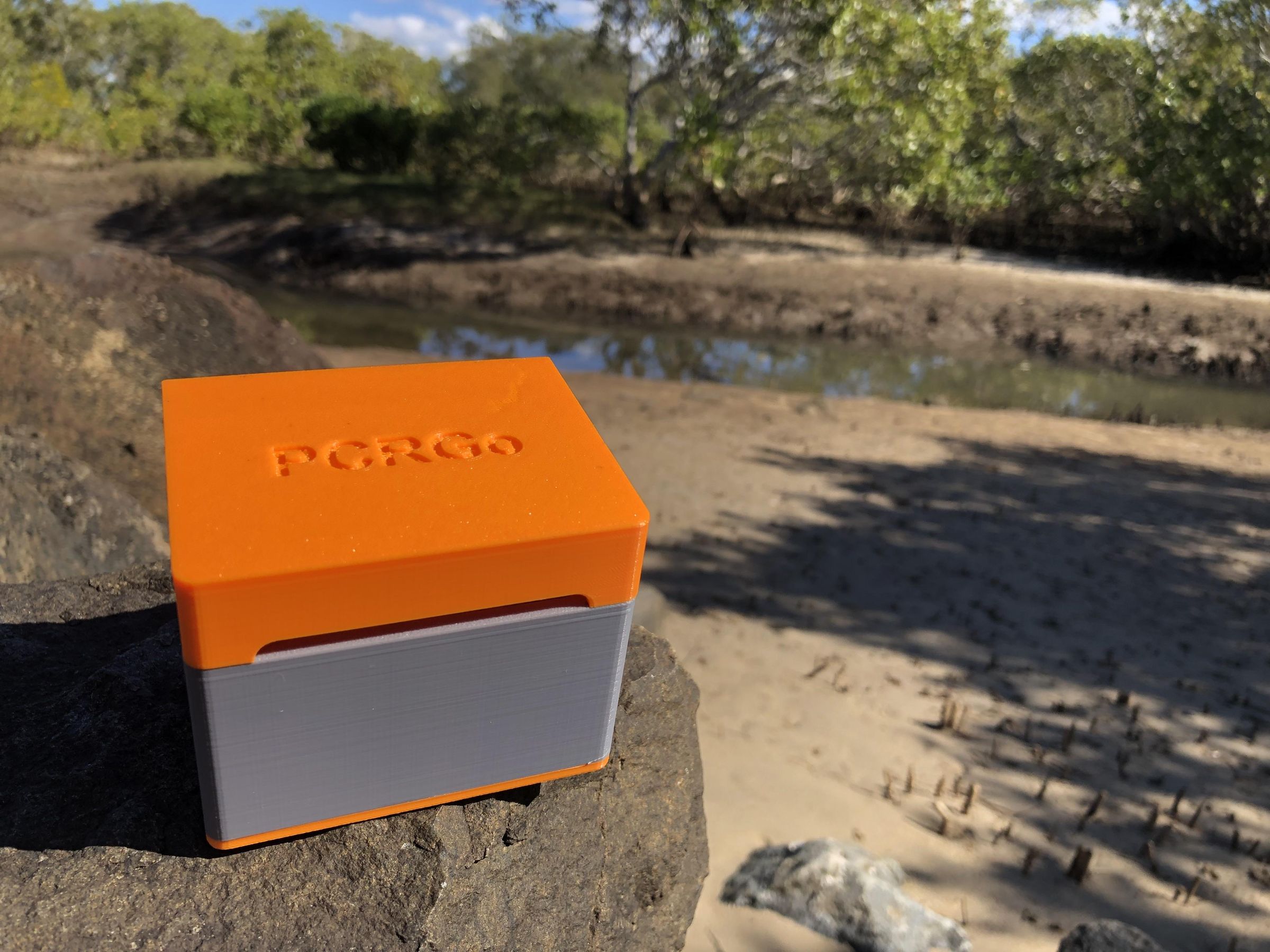
To demonstrate the portability of PCRGo I took it to the mangroves and performed a run (see image above). Mangrove ecology just went molecular!
UPDATE: 10th June 2026
Real World Use: Mycoplasma PCR
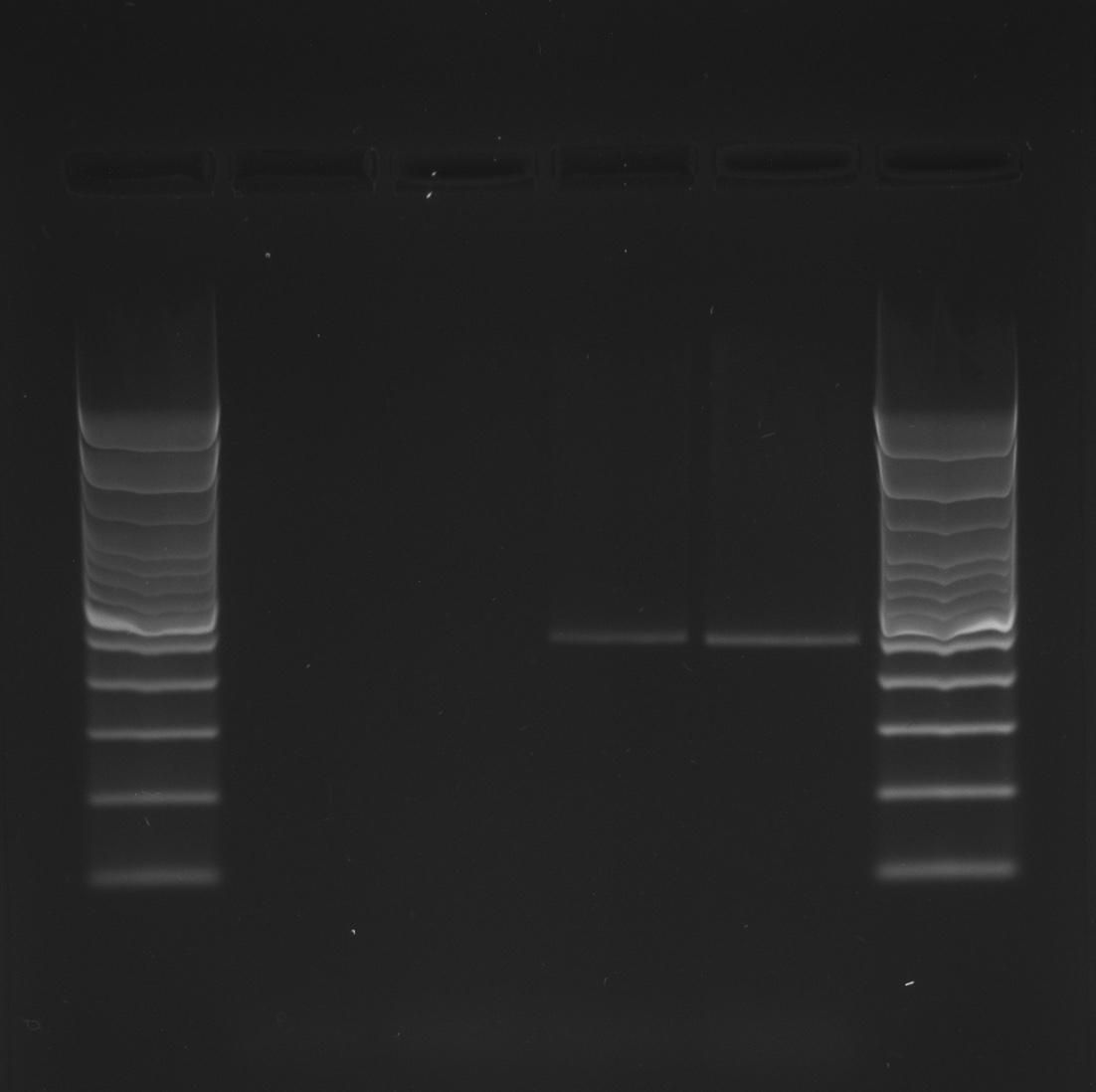
PCRGo was used to identify the Mycoplasma species responsible for causing disease in cattle (see image above).
"Whenever I need a lot of a small part of the DNA of something, I make a lot of it with PCRGo." - A scientist.
Temperature Profile: Initial denaturation 95'C 3 min, 40 cycles of (denaturation 95'C 30 secs, annealing 60'C 30 secs, extension 72'C 20 secs), and a final extension of 72'C 5 min.
Introduction
Every living thing contains genetic instructions that tell its cells how to grow, function, and reproduce. These instructions are stored in molecules called DNA (deoxyribonucleic acid). Scientists can examine these molecules to identify species, diagnose diseases, detect pathogens, study evolution, and even solve crimes.
The challenge is that DNA are often present in extremely small amounts. To analyse them, scientists first need to make millions or even billions of copies of a specific genetic sequence. This process is called amplification and is most commonly performed using a technique known as the Polymerase Chain Reaction (PCR).
PCR works by repeatedly heating and cooling a sample in a device called a thermal cycler. During each cycle, the genetic material is separated, copied, and then copied again, resulting in an exponential increase in the amount of DNA. After 30–40 cycles, a single target sequence can be amplified into millions of copies that can be easily detected and analysed.
Thermal cyclers are essential tools in modern research, medicine, agriculture, biosecurity, and veterinary diagnostics. However, commercial instruments can be expensive and often require mains power, limiting their use in classrooms, field work, and remote locations.
Powered by two replaceable 18650 lithium-ion batteries and built from affordable, readily available components, PCRGo brings PCR technology beyond the laboratory and into classrooms, research settings, and remote field locations, making genetic testing more accessible than ever before and placing the power of a molecular biology laboratory in the palm of your hand.
Supplies
Batteries!!!
Batteries: 18650 lithium-ion cells (2600mAh minimum)
Battery holder: 2 slot 18650 battery holder
Battery protection: 2S 3A BMS board
Build Materials
Fan: Case Fan 5V 0.1A 40mm x 40mm x10mm
Fan switch: NPN transistor (BC546 or equivalent, currently trialing the 2N7000)
Header pins: 15 pin single row female header socket 2.54mm pitch
Heater: 2.6W 3.7V polyimide adhesive heat pad 57mm x 6mm
Heater switch: MOSFET (Note: the original MOSFET used was a 30N06L, this is no longer available, and if you do find one, it may be a clone with a high voltage threshold and not suitable for an ESP32. I am currently trialing the IRLB8721, Adafruit's replacement for the 30N06L, and will update this page with its results.)
Interface for PT100: MAX31865 RTD amplifier
Main controller: ESP32 WROOM-32 development board (30 pins only)
Polarity protection: Schottky diode (1N5819 or equivalent)
Screws: M3 x 6 mm and M3 x 10 mm
Temperature sensor: PT100 class A (2.0 x 2.3 mm)
Washers: Nylon 3 mm
Using PCRGo
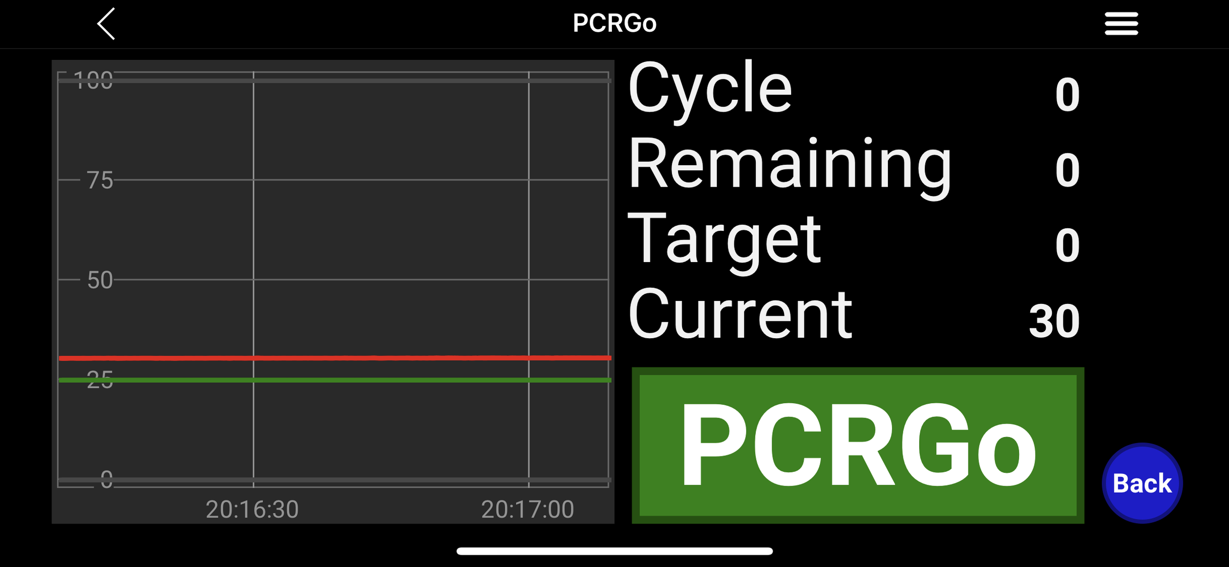
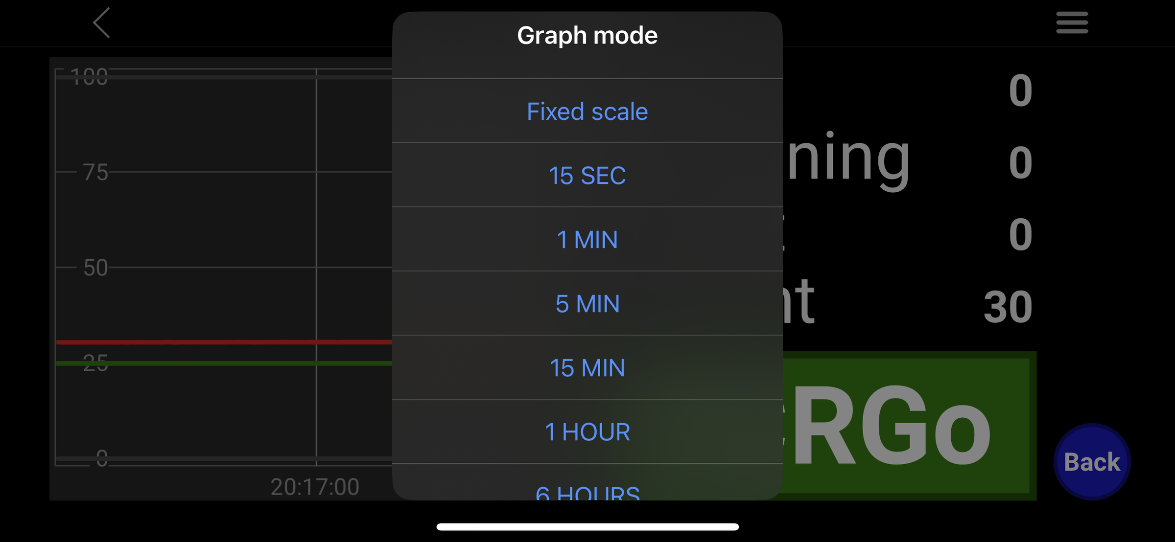
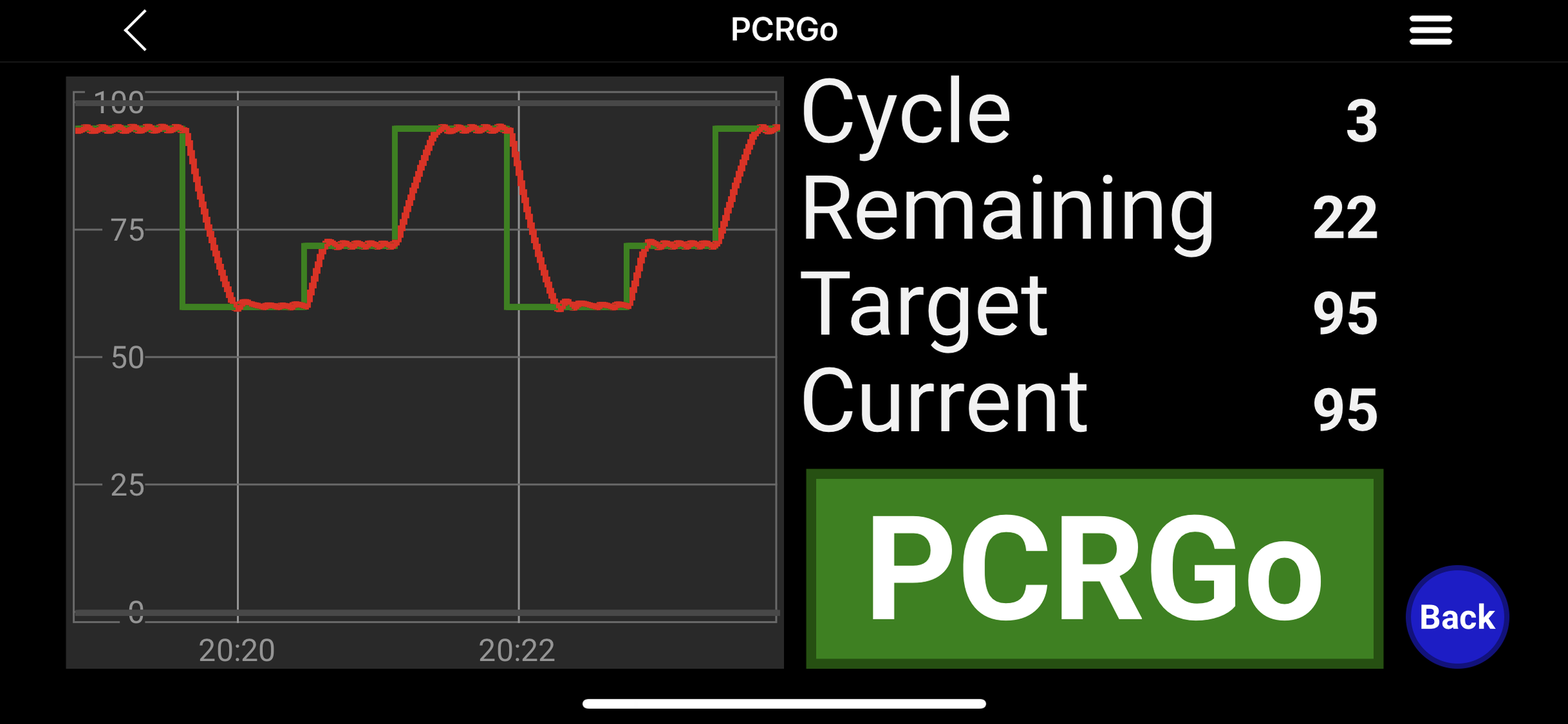
In this section, we will focus on installing RemoteXY onto your device and programming a temperature profile onto the PCRGo. For detailed Instructables covering DNA extraction, preparation of PCR reaction mixes, and visualisation of PCR products (amplicons), please follow the links provided.
Note: In the future, I may develop a battery-powered gel illuminator to complement the PCRGo.
Installing RemoteXY and Connecting to PCRGo
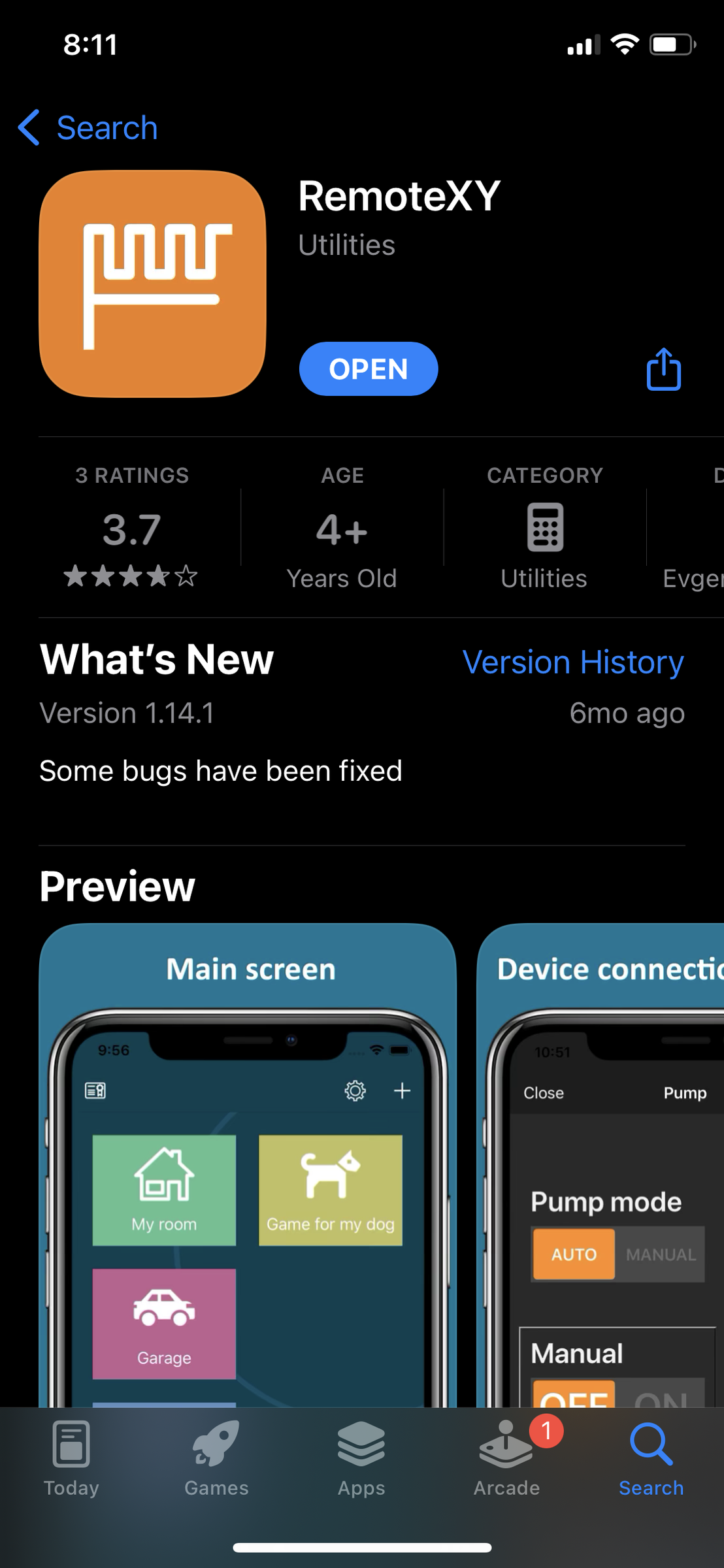
To control PCRGo, download the RemoteXY app from your device's app store. A subscription of approximately AUD $1.95 per month is required to access the features needed to operate PCRGo.
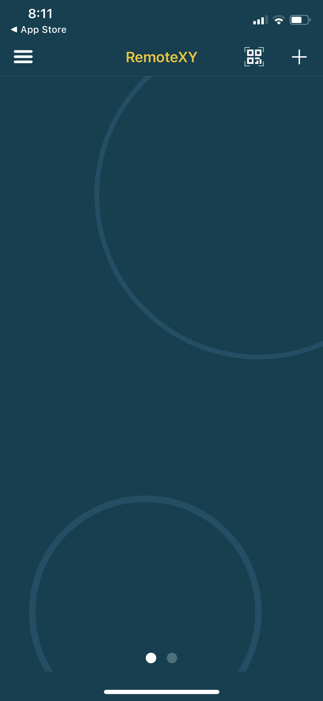
Open the RemoteXY start page and tap the "+" button.
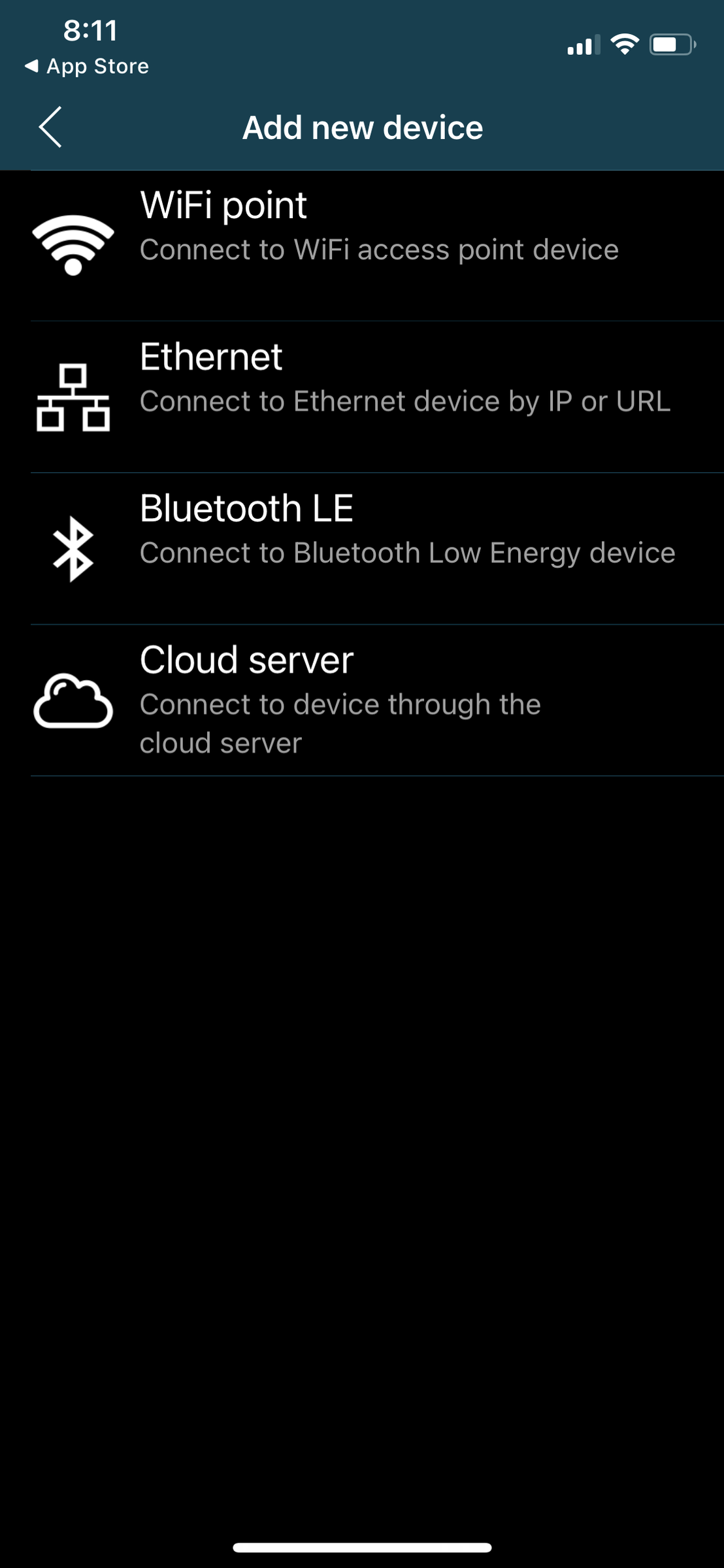
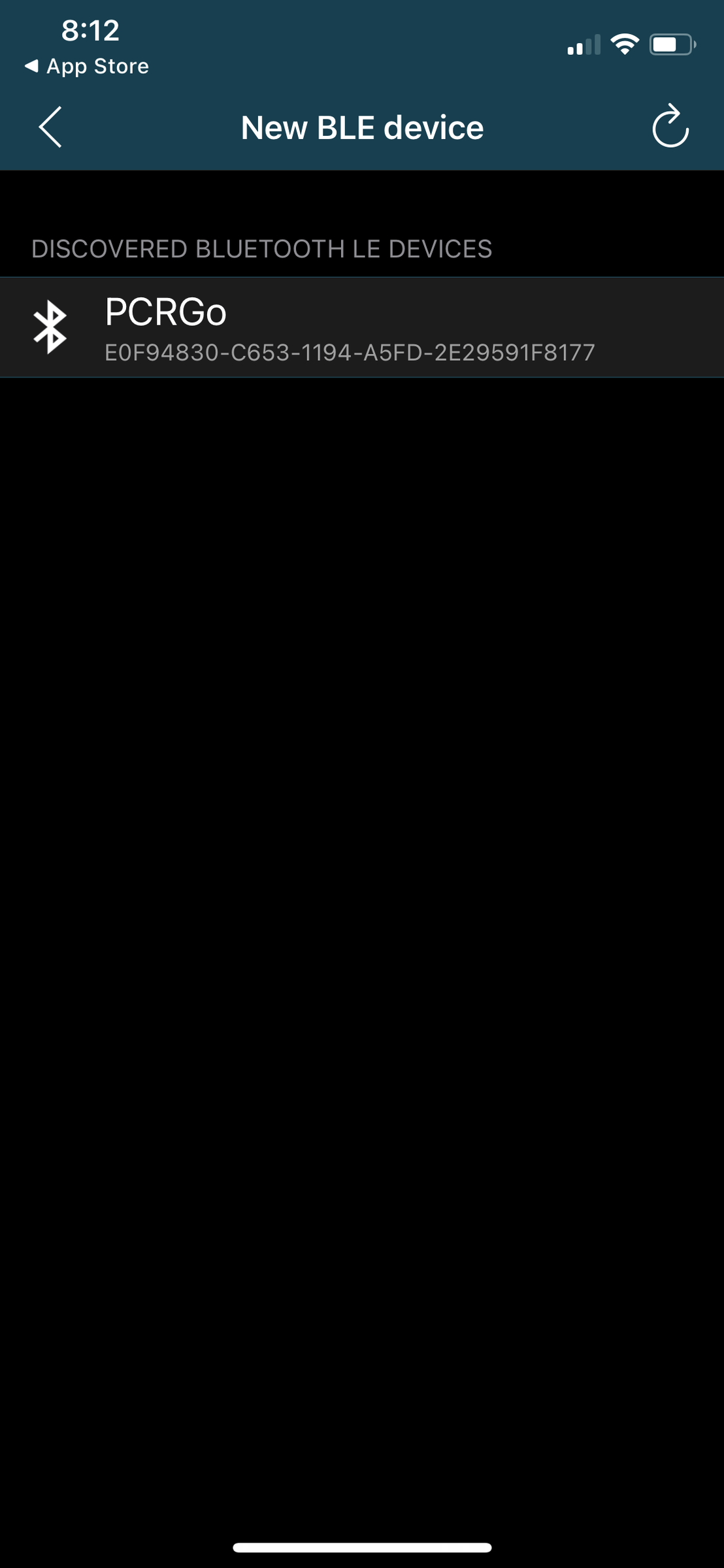
Select "Bluetooth LE" to add a new device.
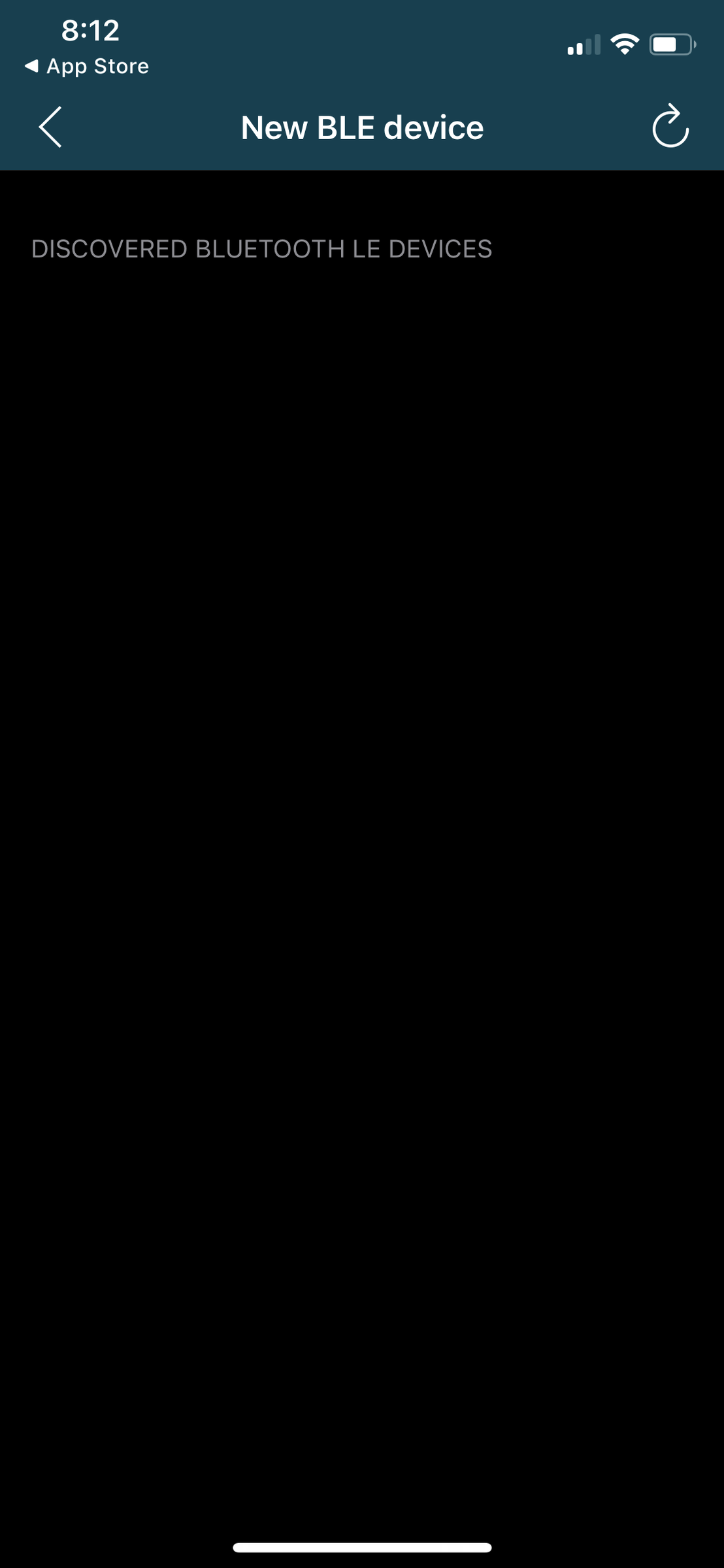
There should not be any available devices listed initially. Turn on PCRGo by inserting the batteries. After a few seconds, PCRGo should become discoverable. Select "PCRGo" from the list of available devices.
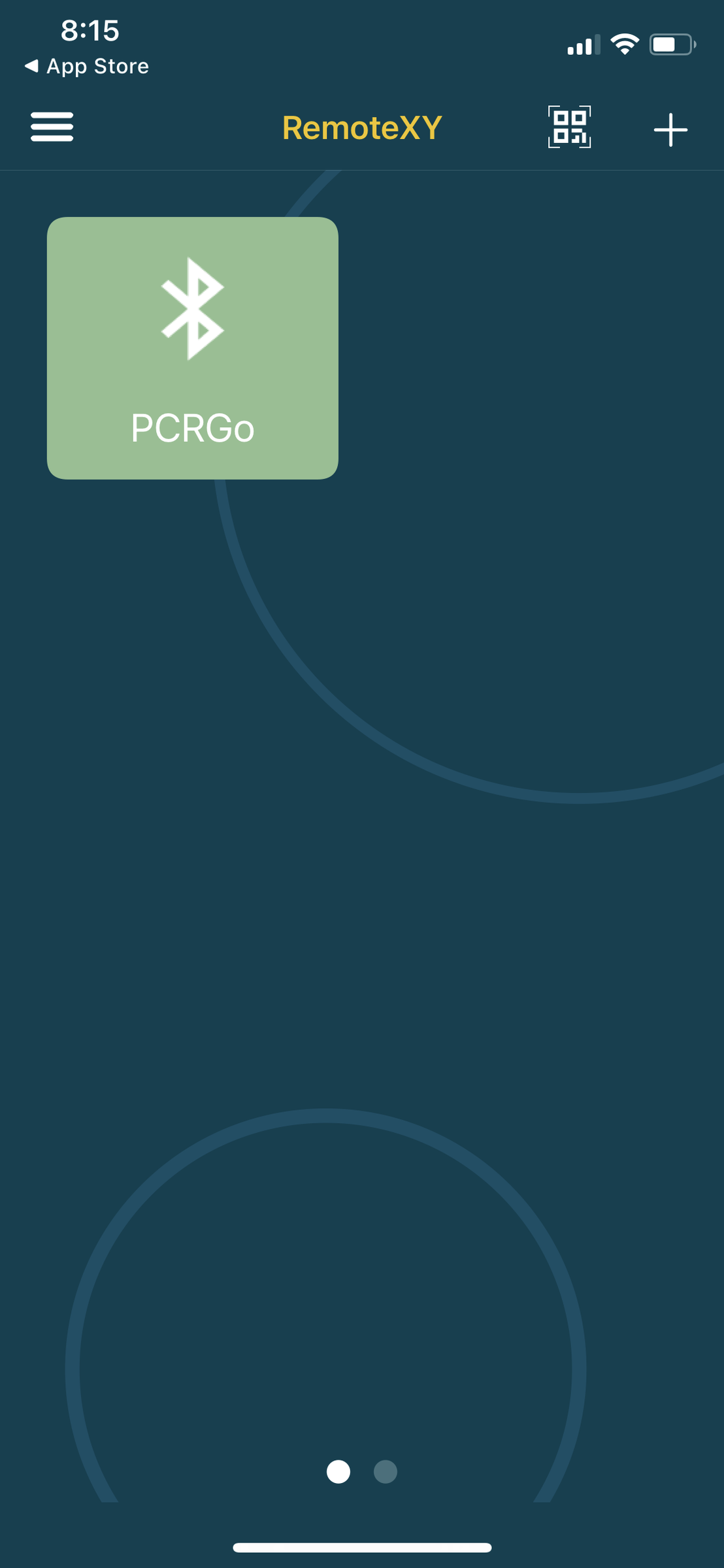
Once paired, PCRGo will appear on the RemoteXY start page and can be selected directly for future connections.
Programming PCRGo
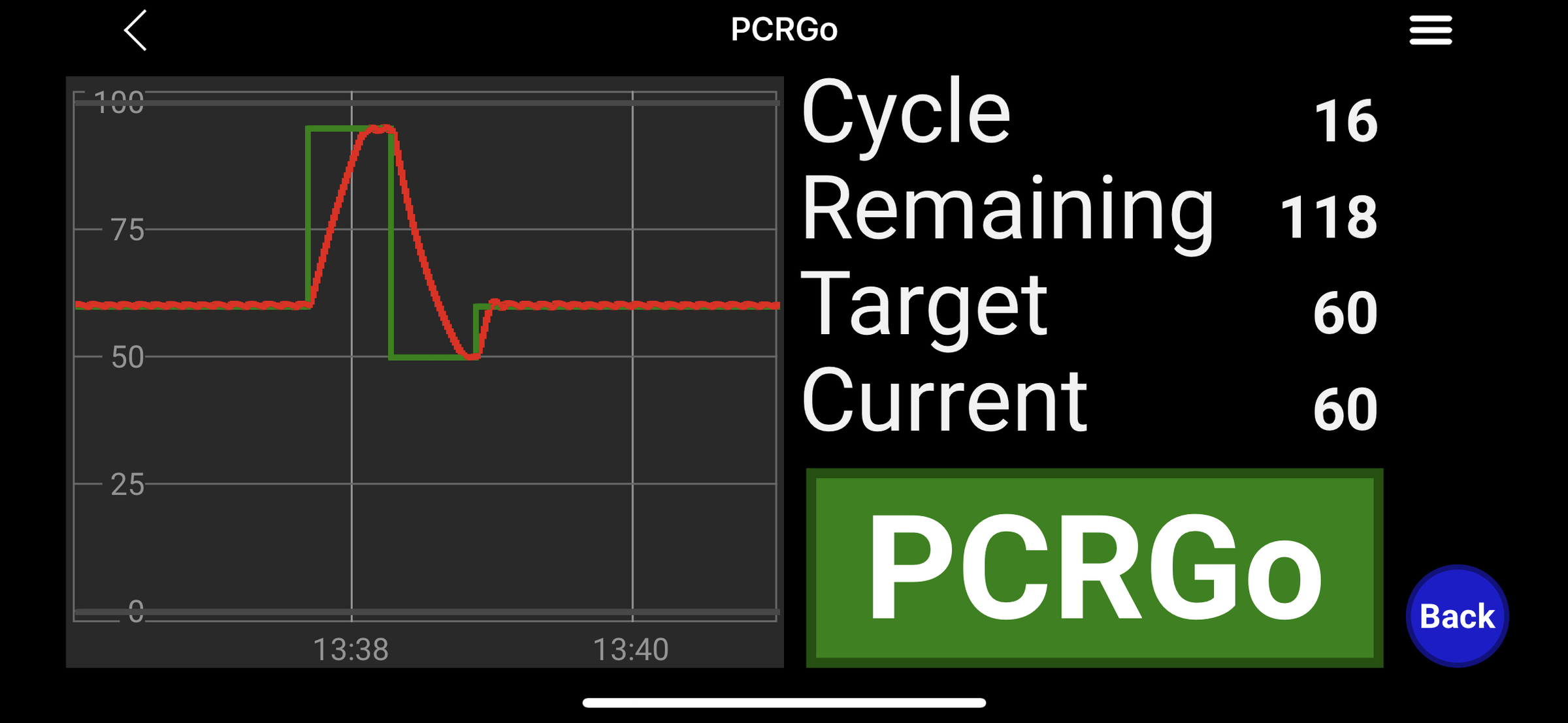
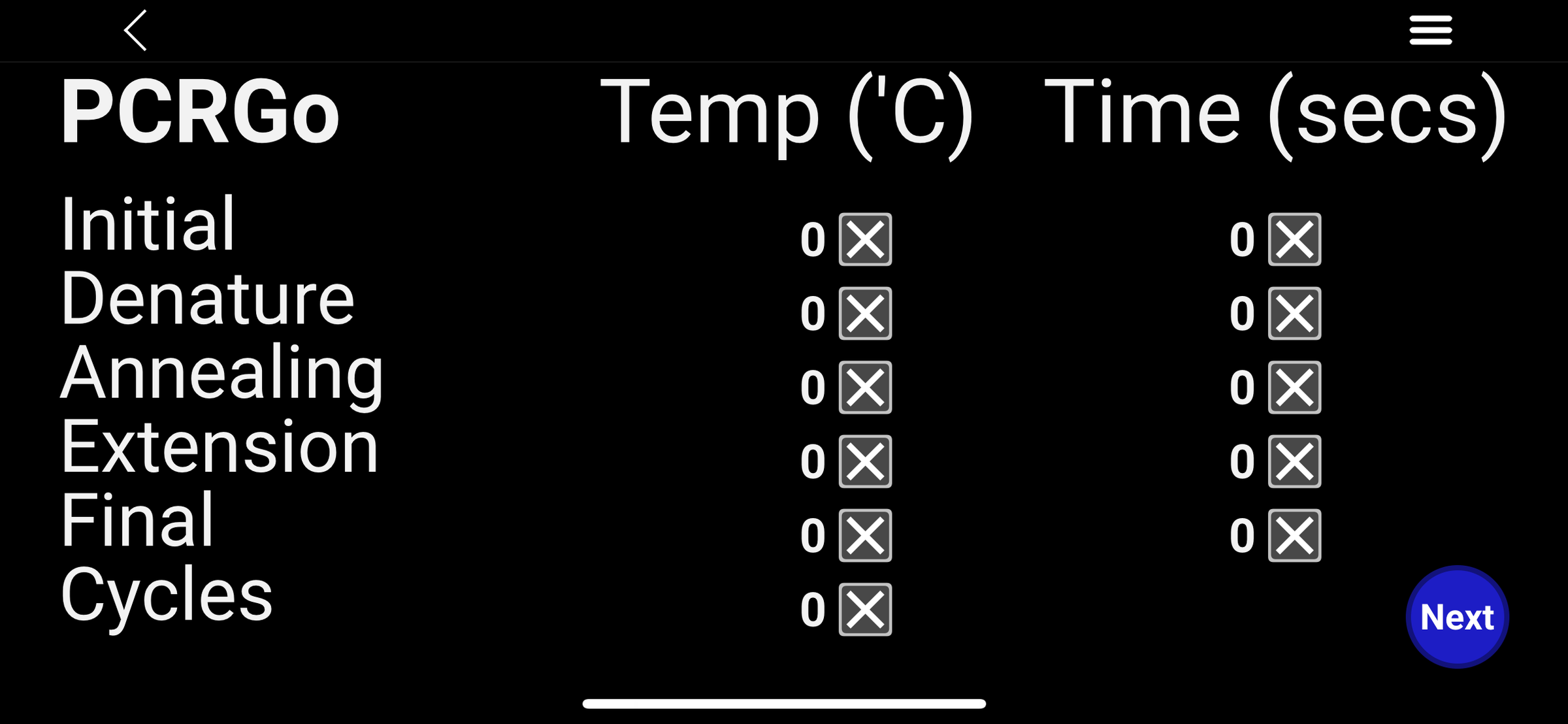
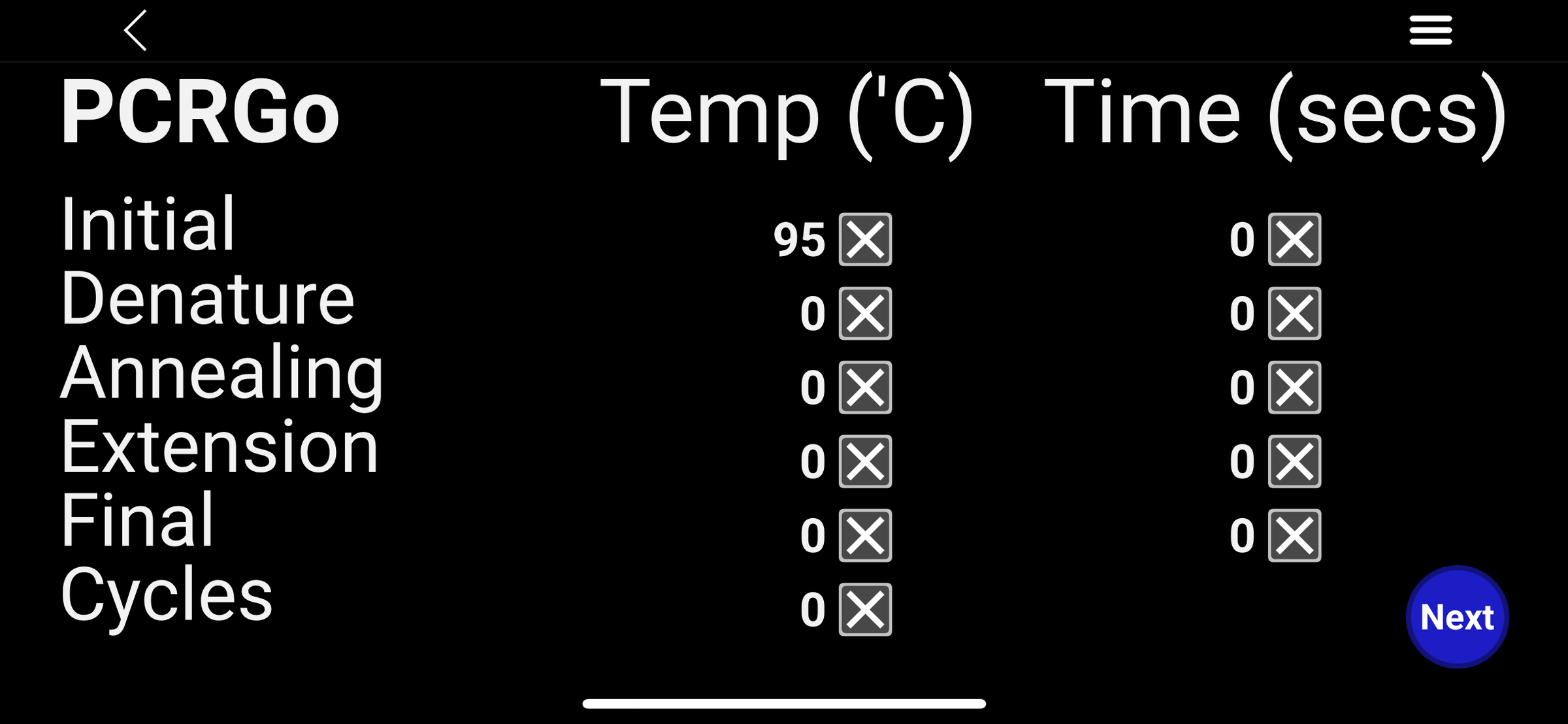
After selecting "PCRGo", the Temperature Profile page will be displayed.
If this is the first time you have used PCRGo, all values will be set to 0. Otherwise, the values from the last run will be displayed.
Selecting the "X" next to a value will reset it to 0.
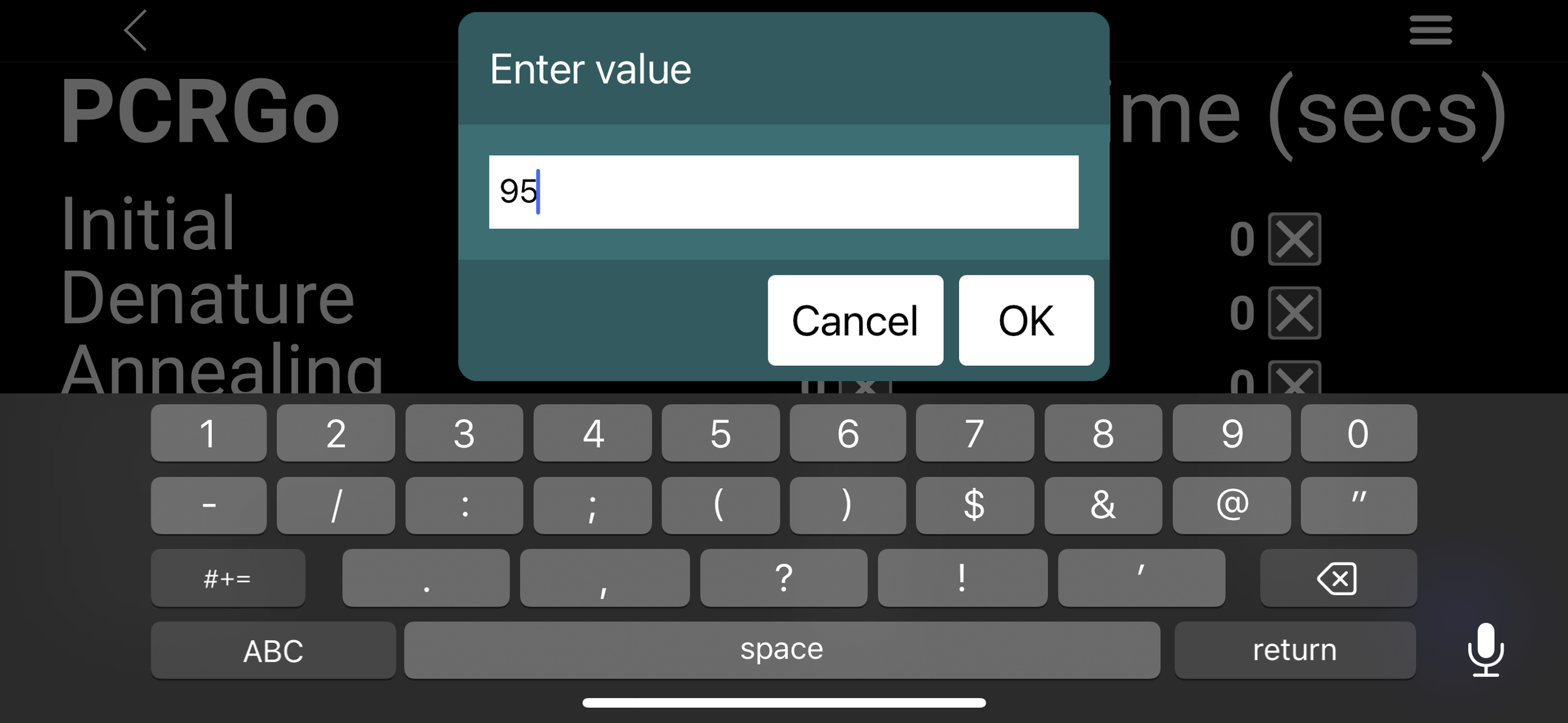
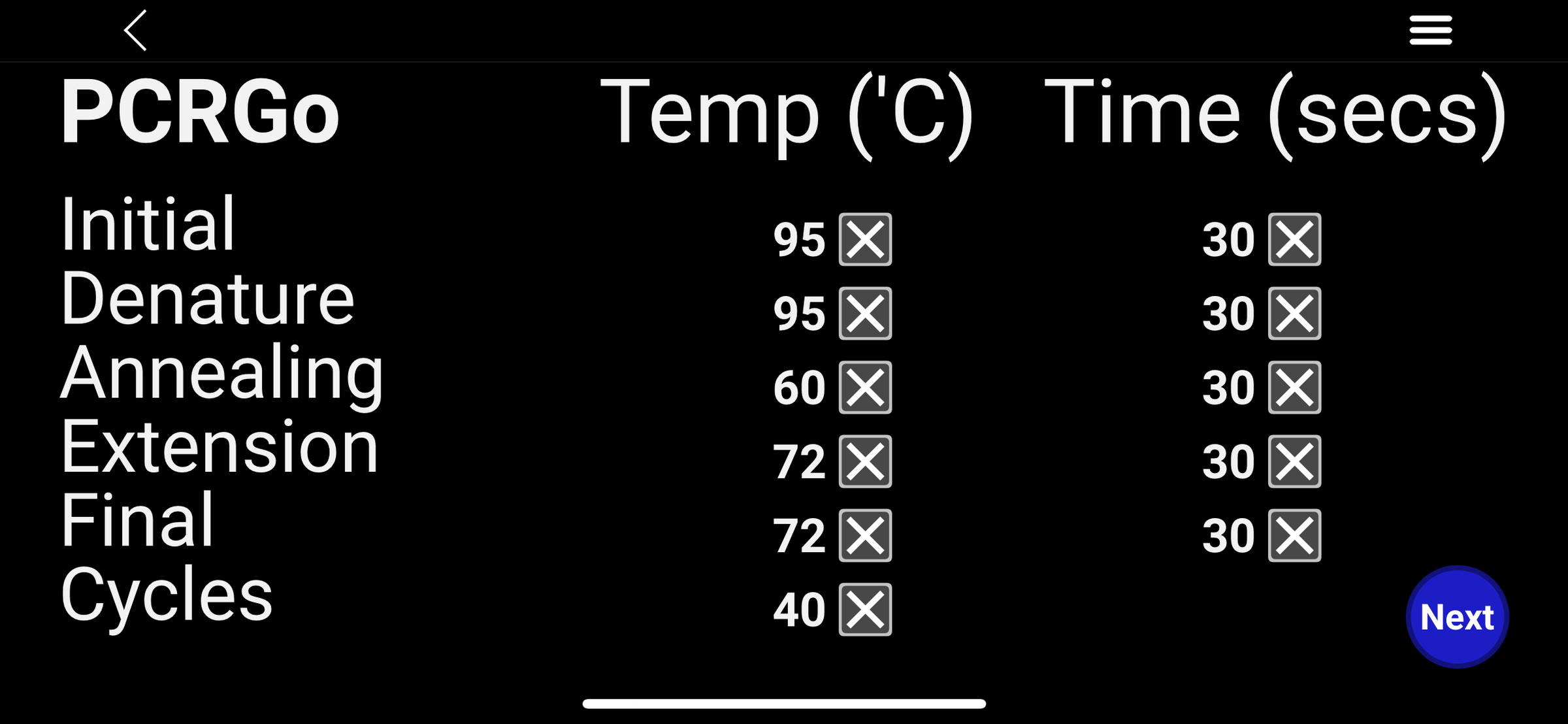
Enter the temperature profile for your PCR by selecting each value. Temperature is entered in degrees Celsius (°C) and time is entered in seconds, so a 5-minute step should be entered as 300 seconds.
Initial Denaturation
This is the temperature at which the double-stranded DNA is separated into single strands for the first time. If you are using a hot-start DNA polymerase, this step also activates the enzyme by removing inhibitory antibodies or chemical modifications. It is typically performed at 95°C.
Note: DNA polymerase (commonly called Taq polymerase) is the enzyme that copies the DNA during PCR.
Denaturation, Annealing and Extension
These three steps make up each PCR cycle.
- Denaturation separates the double-stranded DNA into single strands, typically at 95°C.
- Annealing is the temperature at which the primers bind to their complementary DNA sequence. For example, primers designed to specifically detect Mycoplasma spp. and not E. coli.
- Extension is the temperature at which the DNA polymerase synthesises new DNA strands from the bound primers. For Taq polymerase, this is typically 72°C.
Cycles
This is the number of times the denaturation, annealing and extension steps are repeated, typically 30–40 cycles. PCR amplification is exponential. In an ideal reaction, each cycle doubles the amount of DNA. Starting with a single DNA molecule, 40 cycles can theoretically produce more than one trillion copies (1,099,511,627,776).
Final Extension
The final extension step allows the DNA polymerase to complete any partially synthesised DNA strands before the reaction finishes. This helps ensure that full-length PCR products are generated for downstream applications such as sequencing or cloning.
Sourcing Components and Manufacturing Parts


Sourcing Components
The batteries and build materials can be purchased from a wide range of online suppliers, including eBay, Amazon, DigiKey, RS Components, and many others. Rather than linking to specific listings that may become unavailable or be expensive to ship internationally, I recommend searching for each item and purchasing from a supplier located close to you to minimise postage costs and delivery times.
Note: If there is enough interest in the project, a complete DIY kit containing all required components may be made available in the future.
Manufacturing Parts
- Download the zipped PCB and Heat Block files from my Public Dropbox.
- I used PCBWAY to manufacture the PCB and print the heat block using aluminium. JLCPCB can also manufacture PCBs. Tutorials for uploading your PCB files and uploading your 3D printing files can be found here.
- Files for printing the case for your PCRGo can be found on MakerWorld. I used PETG as it has a higher melting temperature and is better suited for outdoor use.
Installing the Header Pins
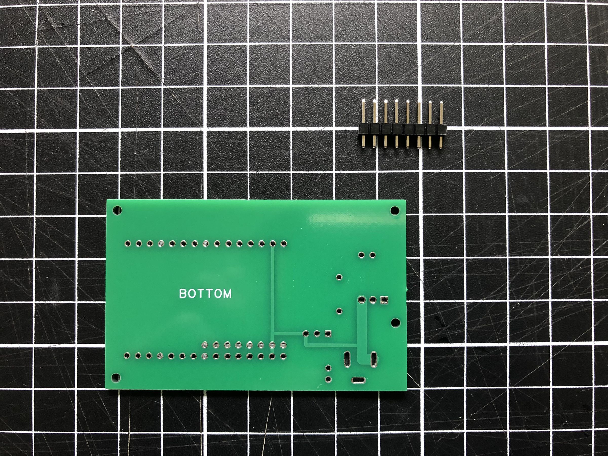
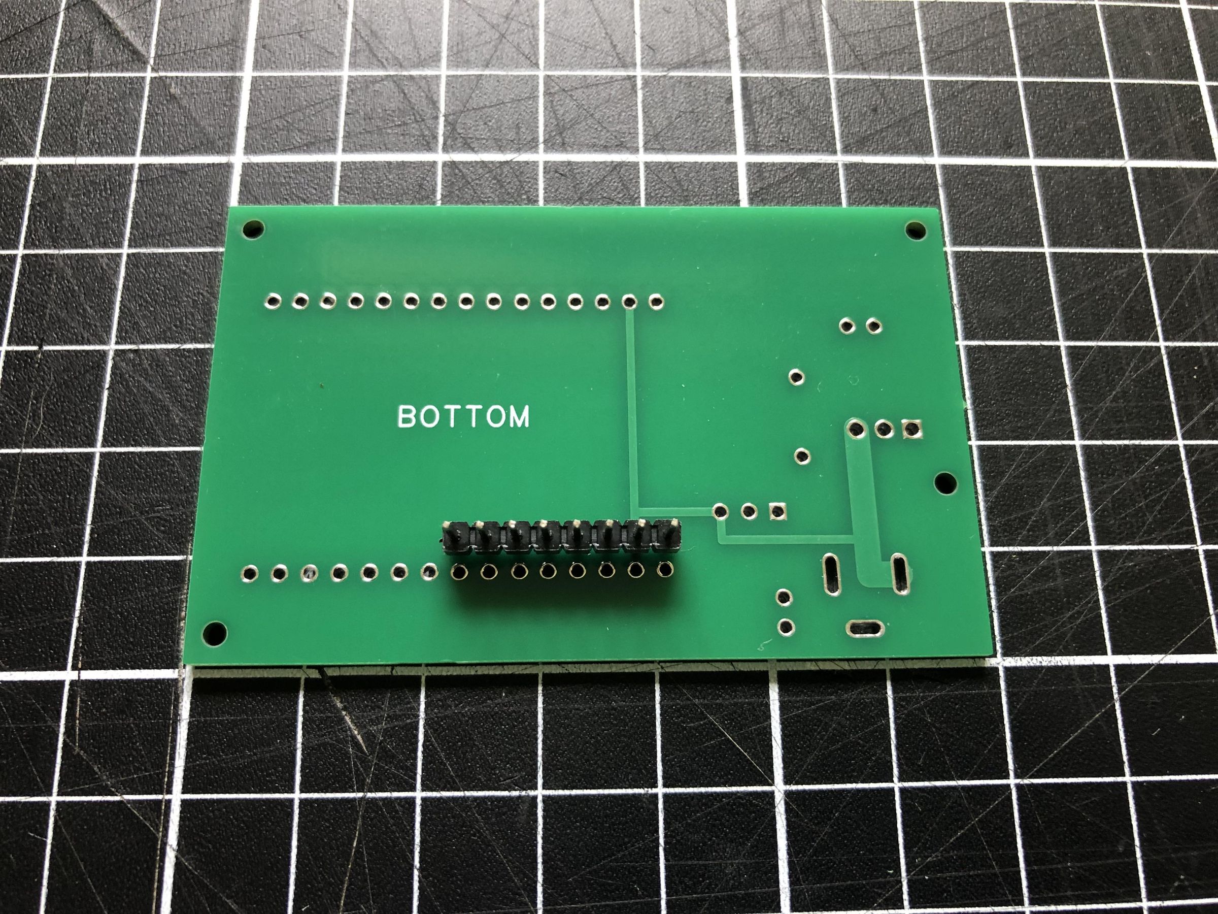
Let's start building PCRGo by attaching the header pins for the MAX31865 module. Insert the header pins into the BOTTOM of the PCB as shown. Turn the board over and solder each pin into place, ensuring the header remains perpendicular to the PCB.
Installing the Header Sockets
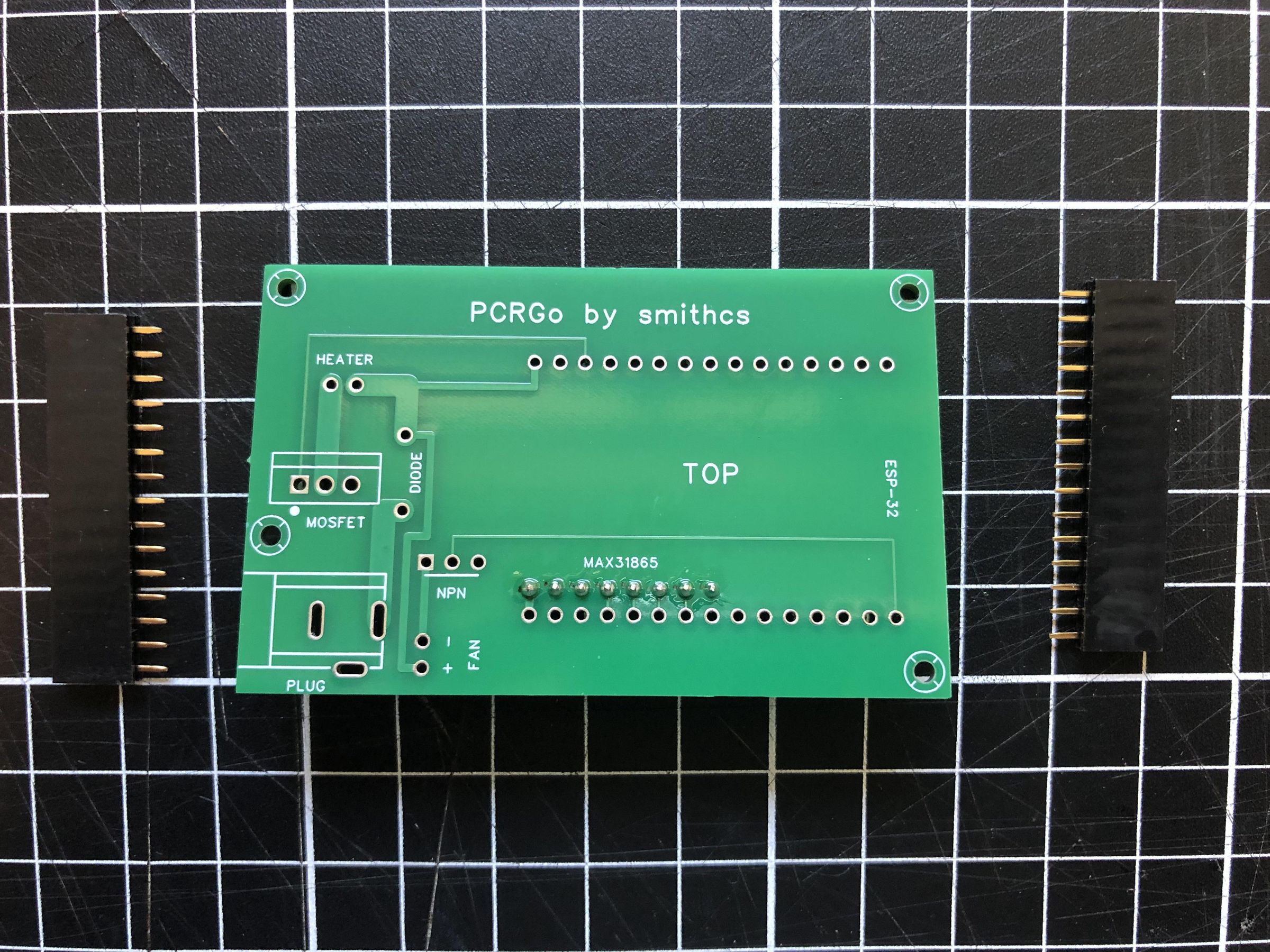
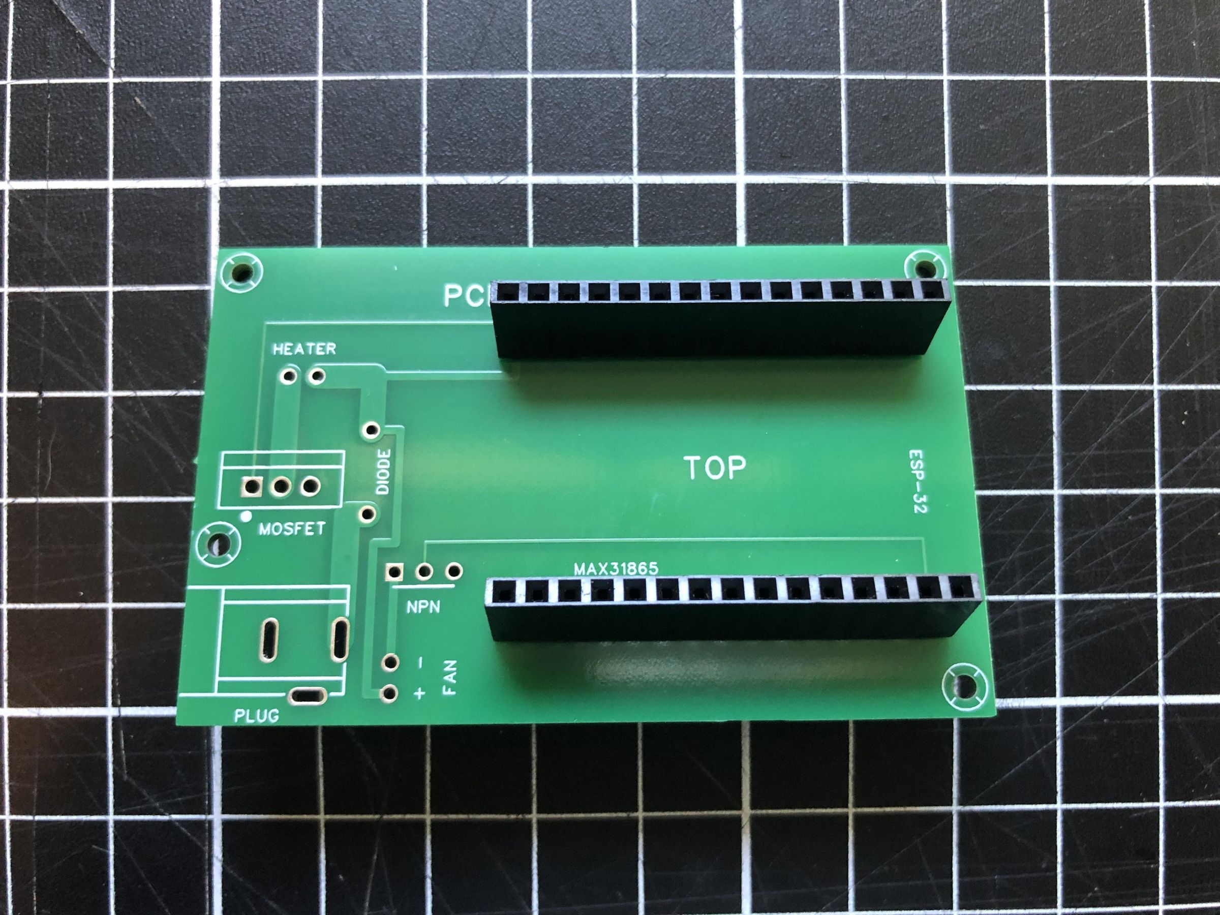
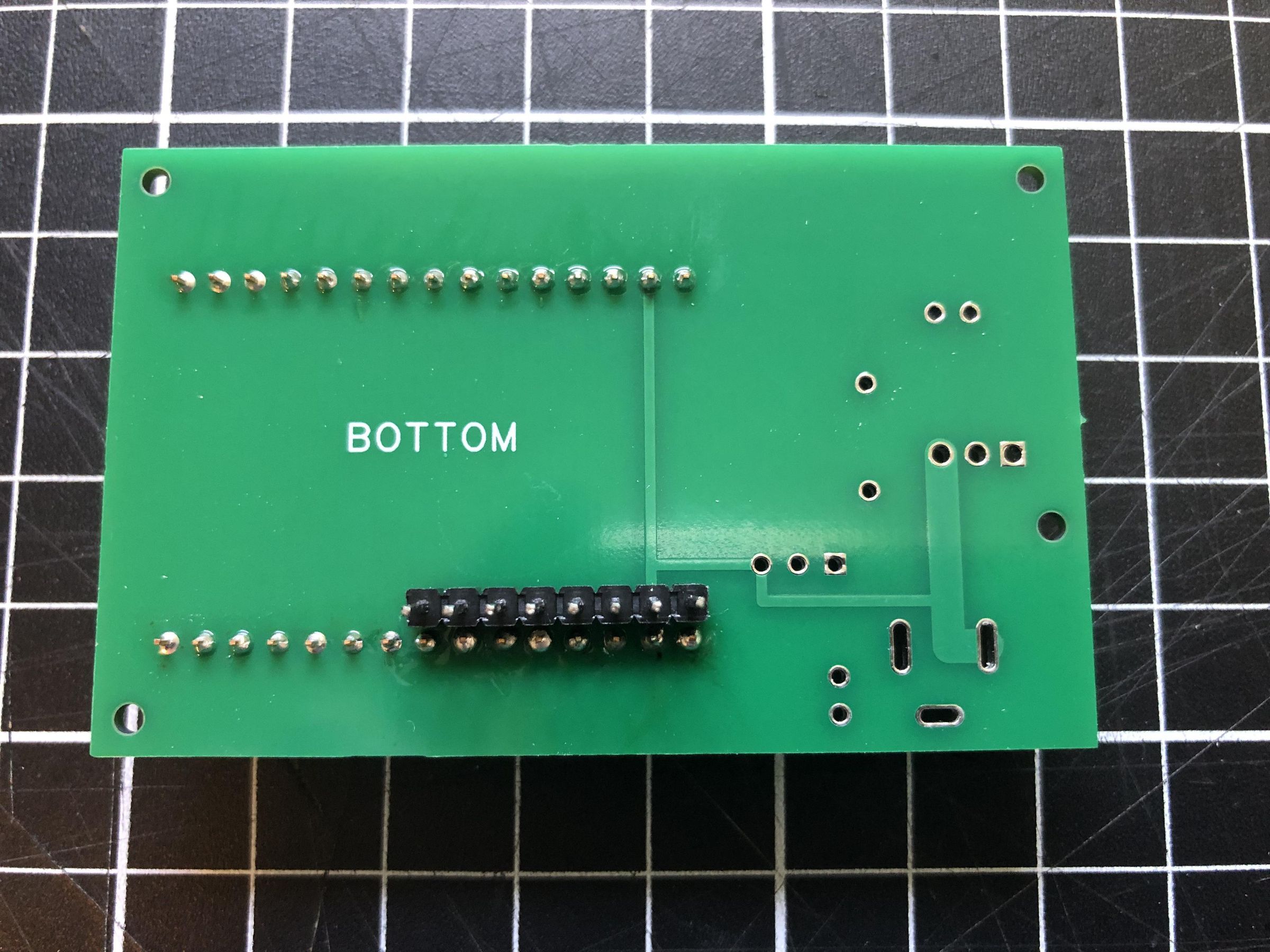
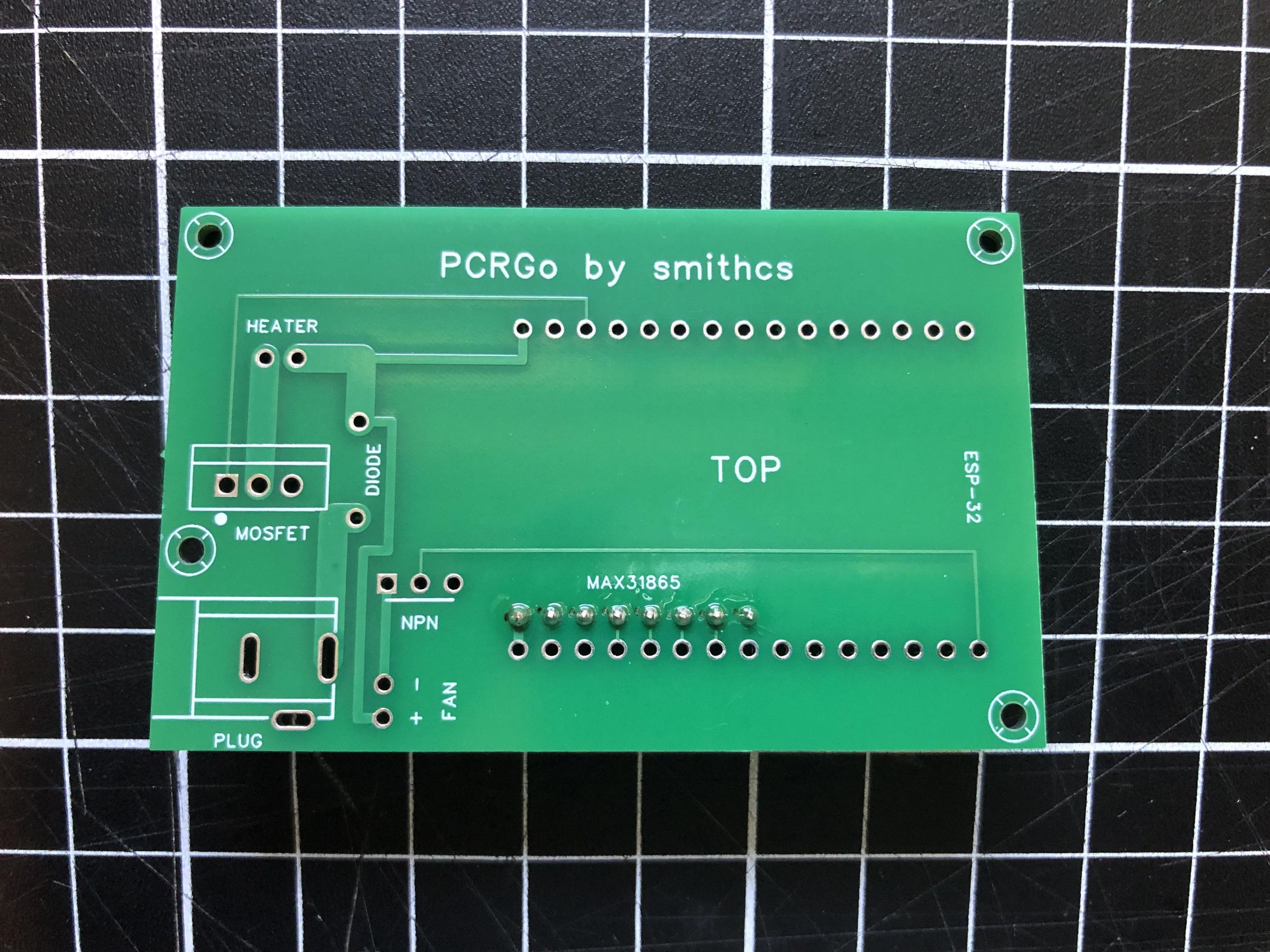
Next, insert the female header sockets for the ESP32 into the TOP of the PCB as shown. Turn the board over and solder each pin into place, ensuring the headers remain straight and parallel to each other. This will allow the ESP32 to be plugged in after the remaining components have been assembled.
Installing the Components
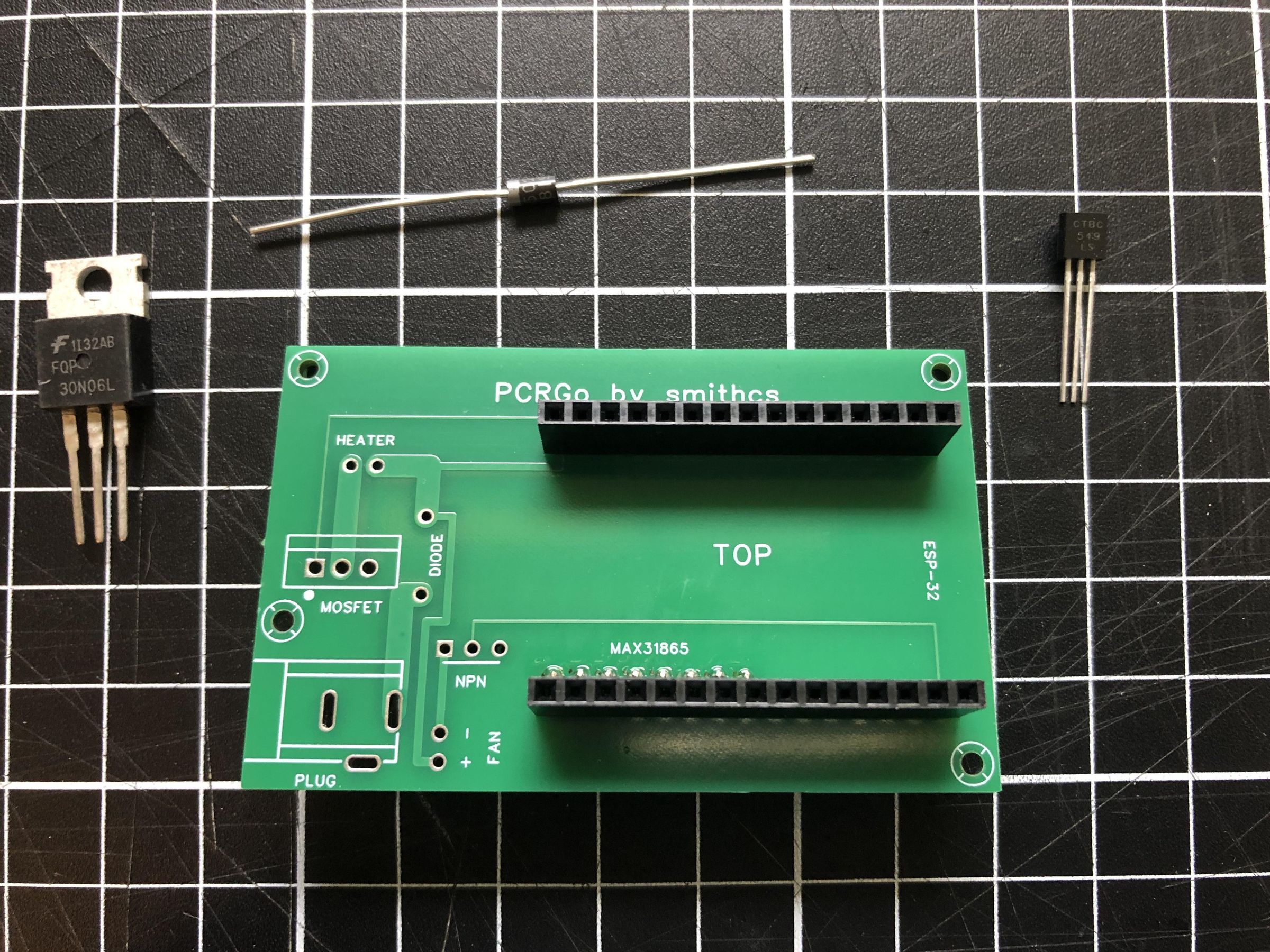
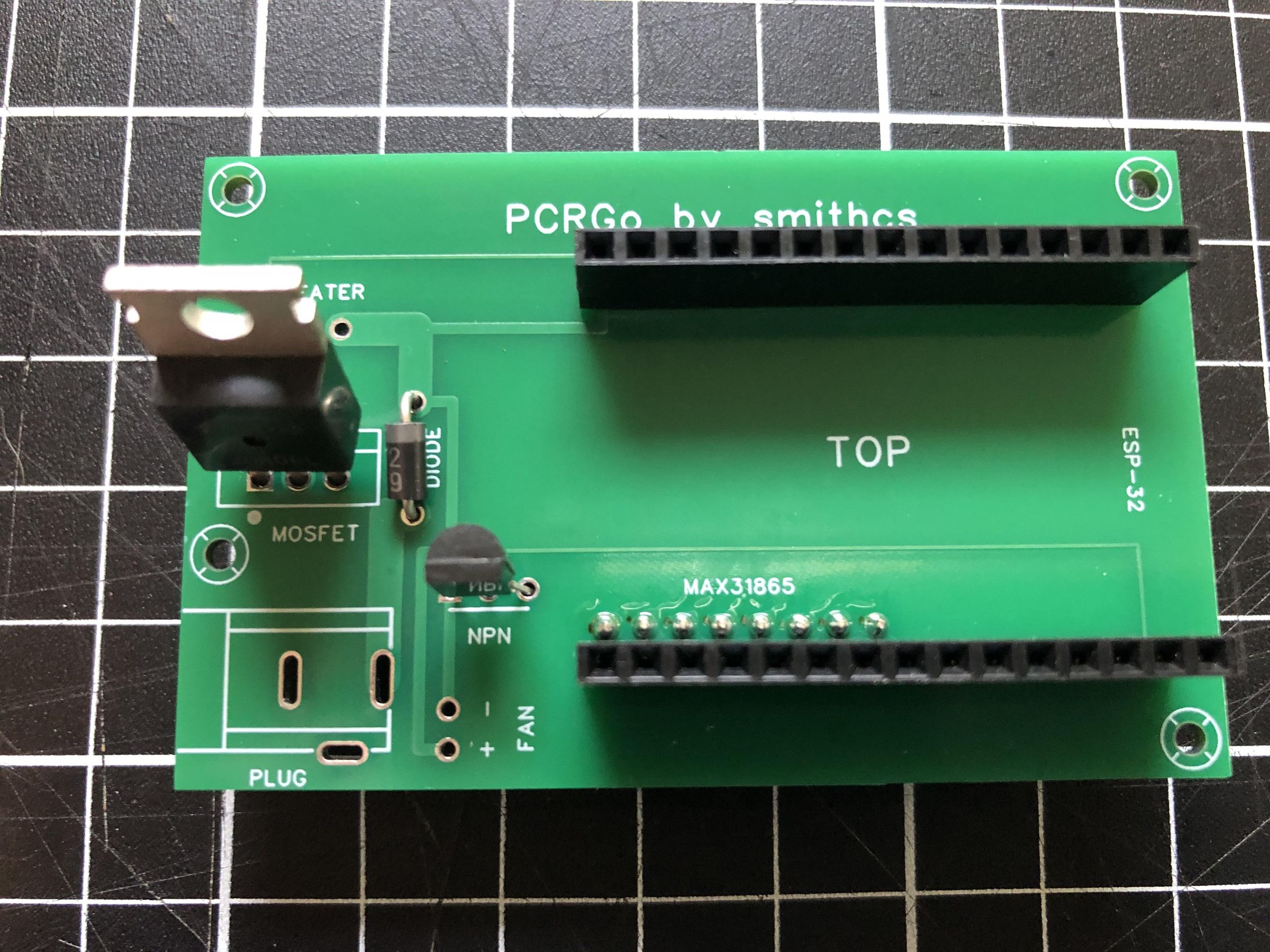
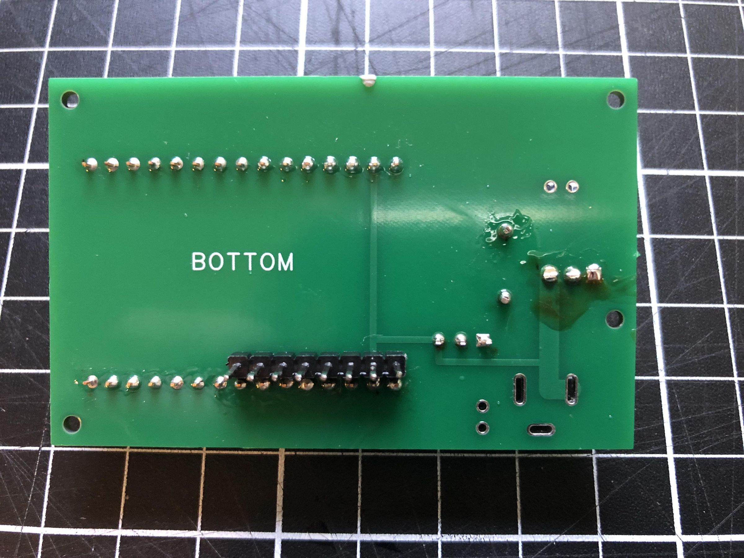
Next, insert the MOSFET, NPN transistor, and Schottky diode into the TOP of the PCB as shown in the images. Ensure that each component is oriented exactly as shown. Correct orientation is essential for proper operation and will help prevent damage to the components or short circuits when the PCB is powered. Turn the PCB over and solder the leads of each component in place. Once all of the joints have been soldered, trim the excess leads close to the PCB using side cutters.
Installing the MAX31865
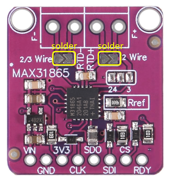
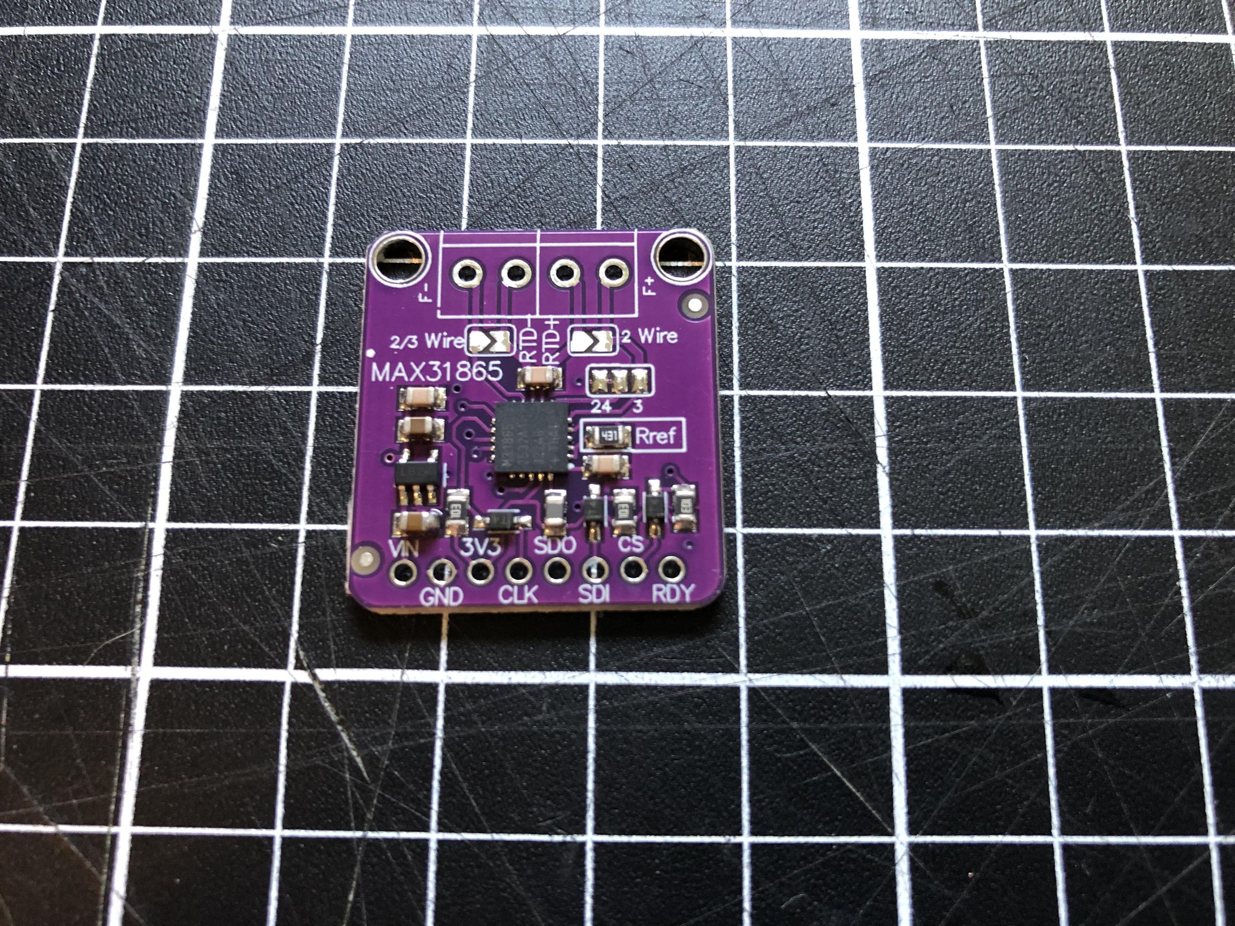
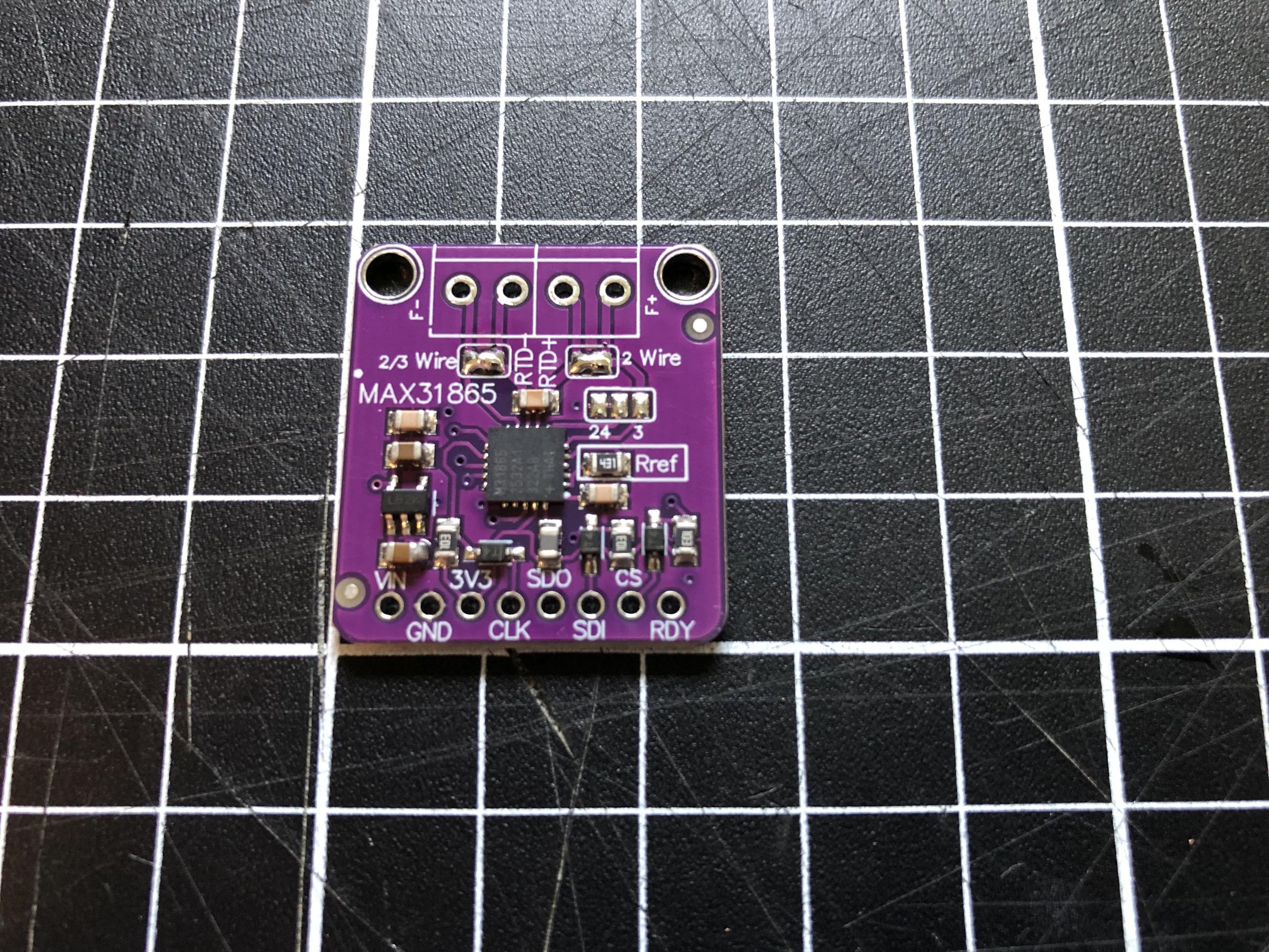
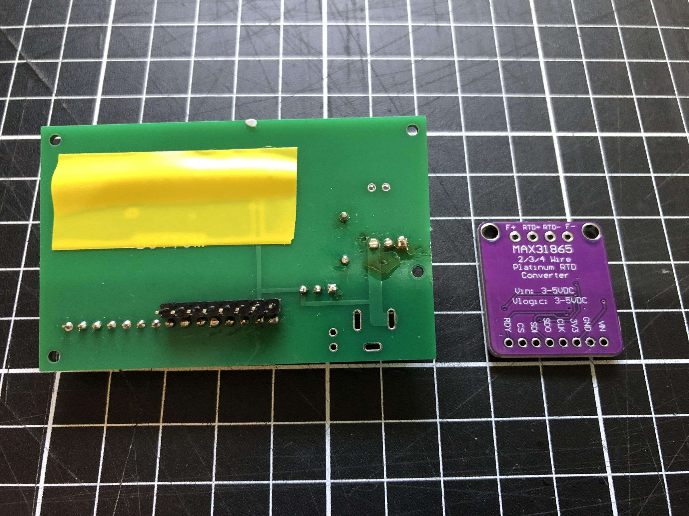
Before installing the MAX31865 module, solder the two configuration pads together so that the contacts are electrically connected. Refer to the images showing the before and after configuration.
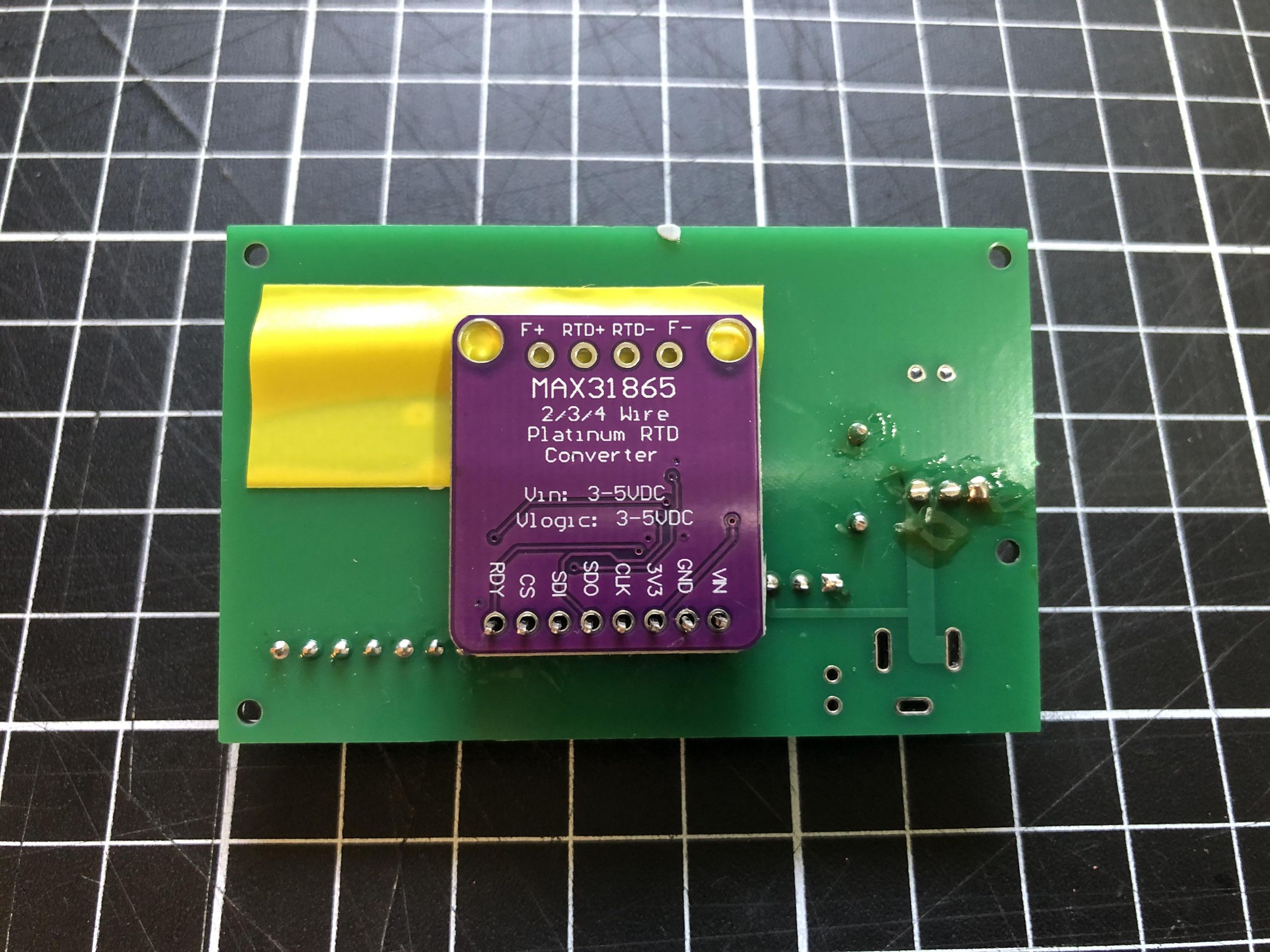
Next, apply a small piece of insulating tape over the exposed female header sockets on the PCB. This prevents the underside of the MAX31865 module from making contact with the sockets and causing a short circuit.
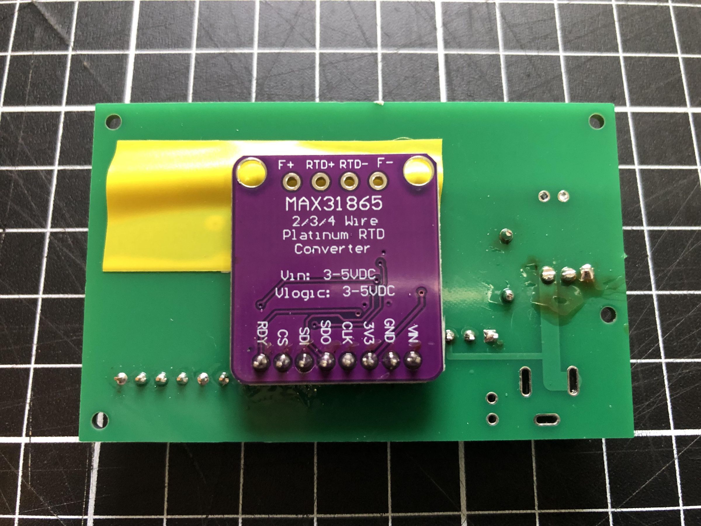
Turn the MAX31865 module upside down and place it onto the header pins as shown in the images. Ensure that the module is fully seated and correctly aligned, then solder each header pin in place.
Preparing the Heat Block
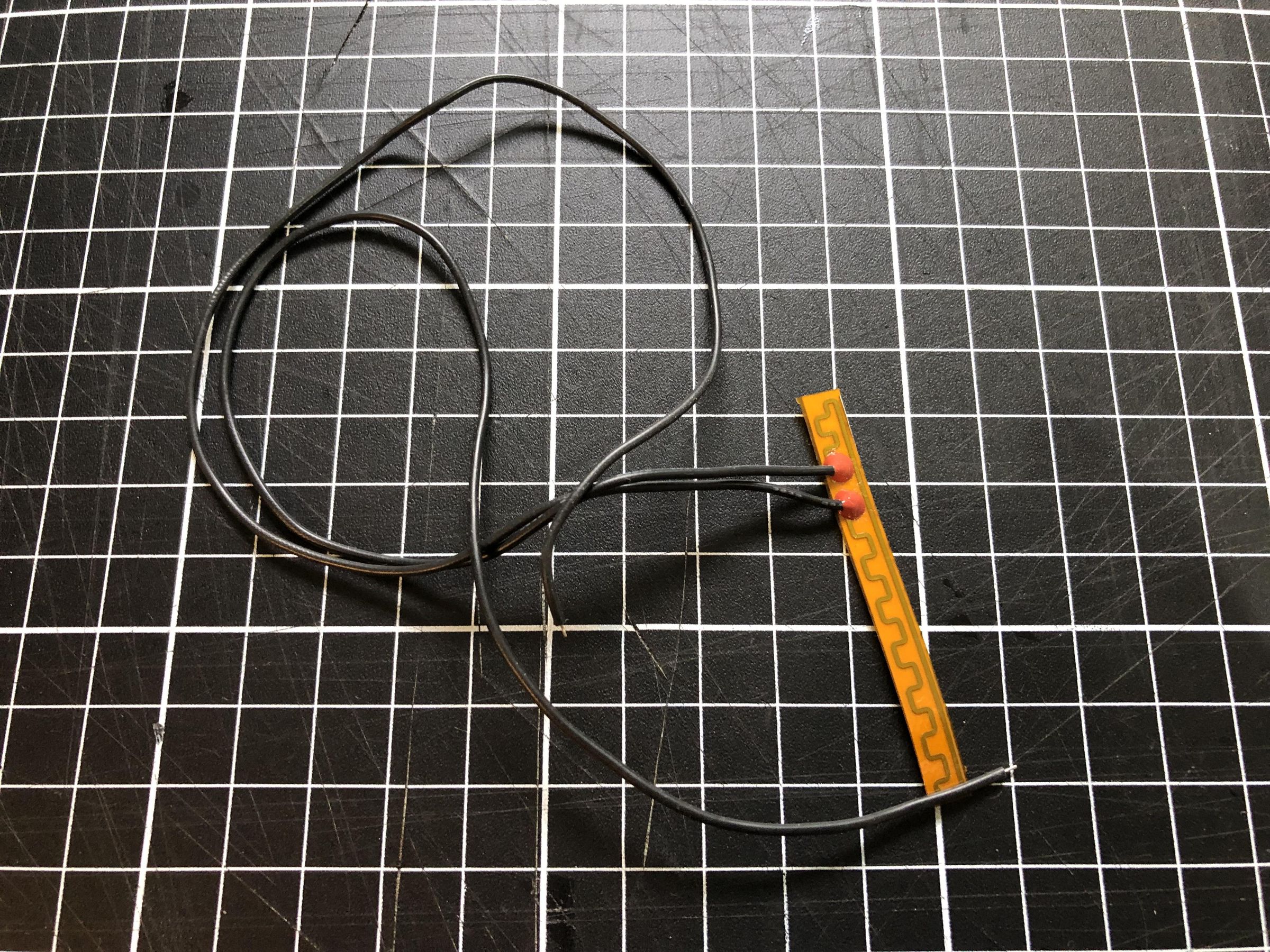
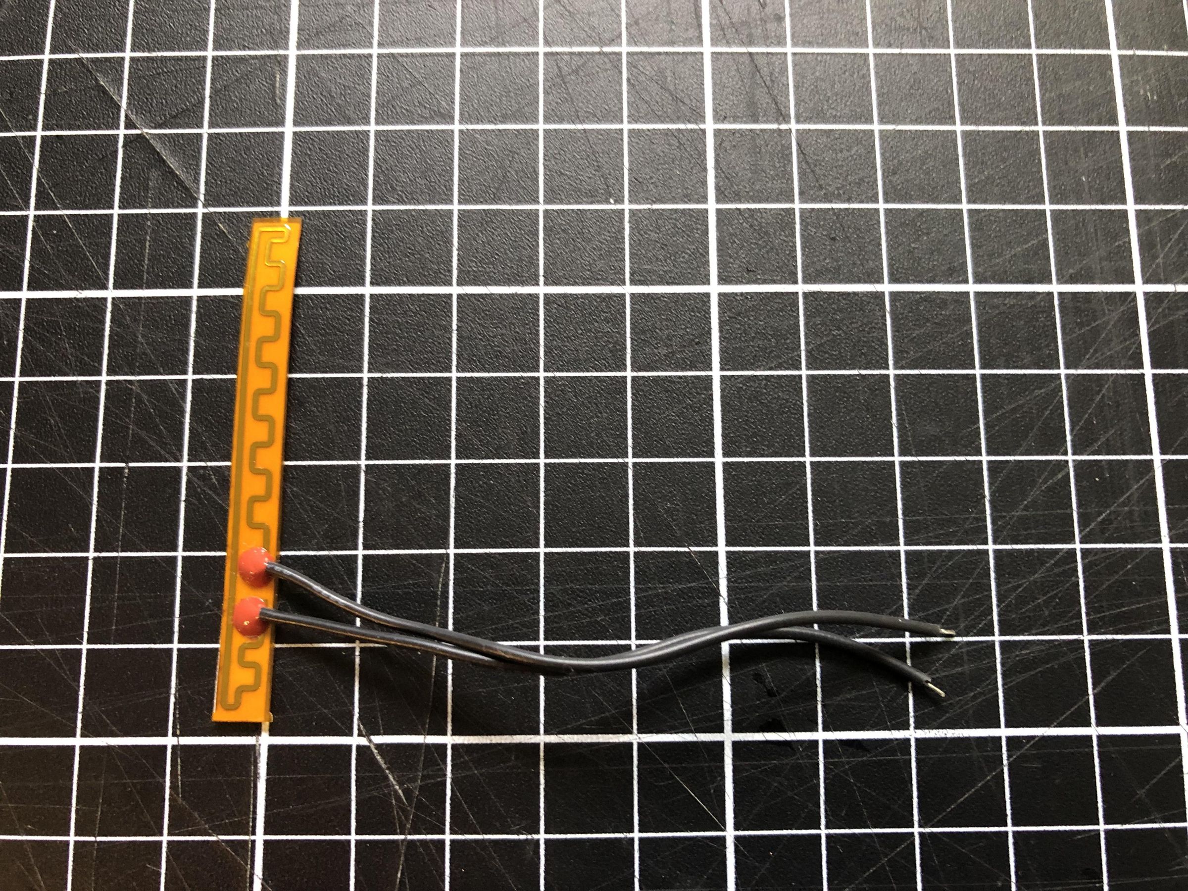
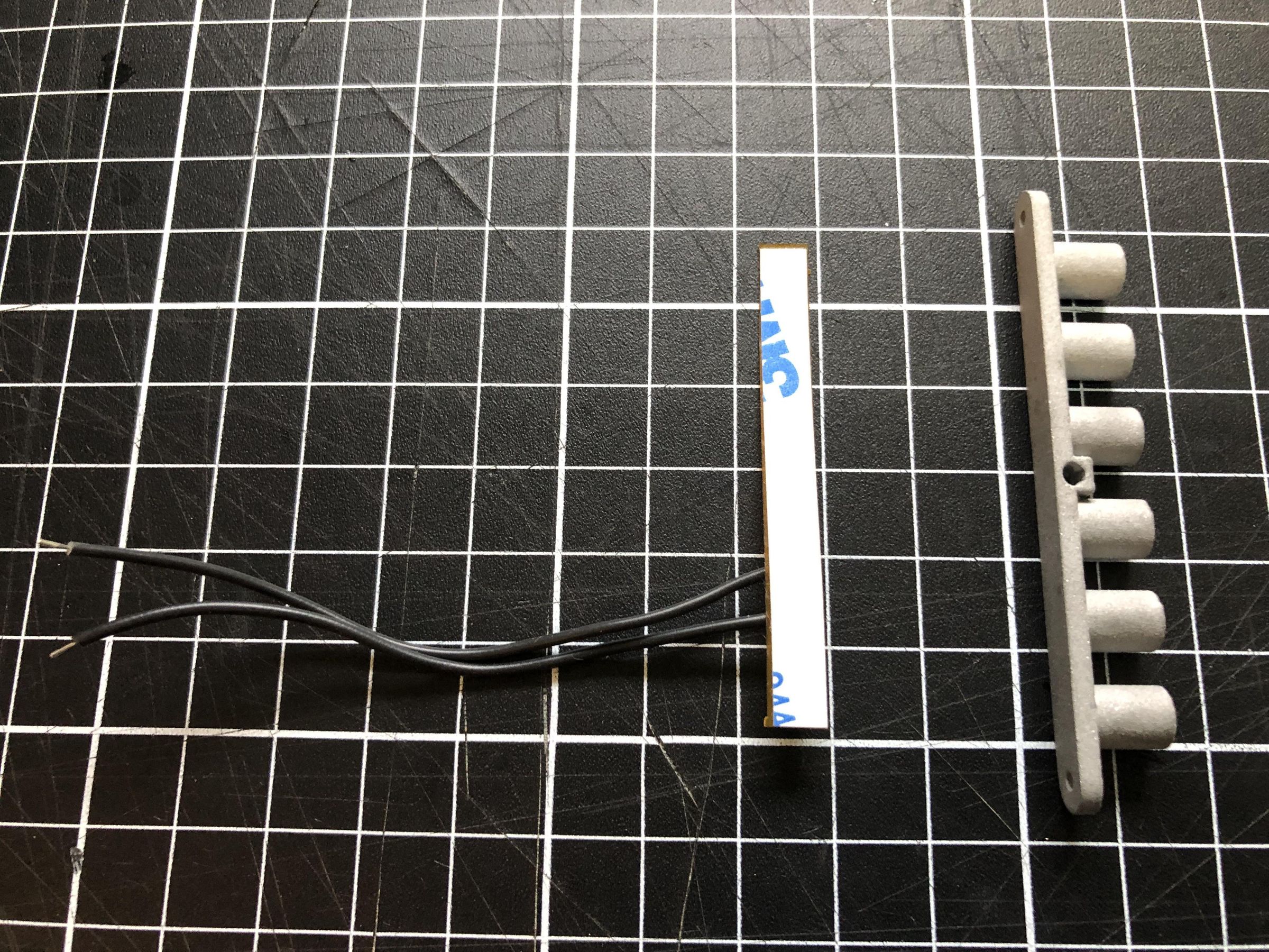
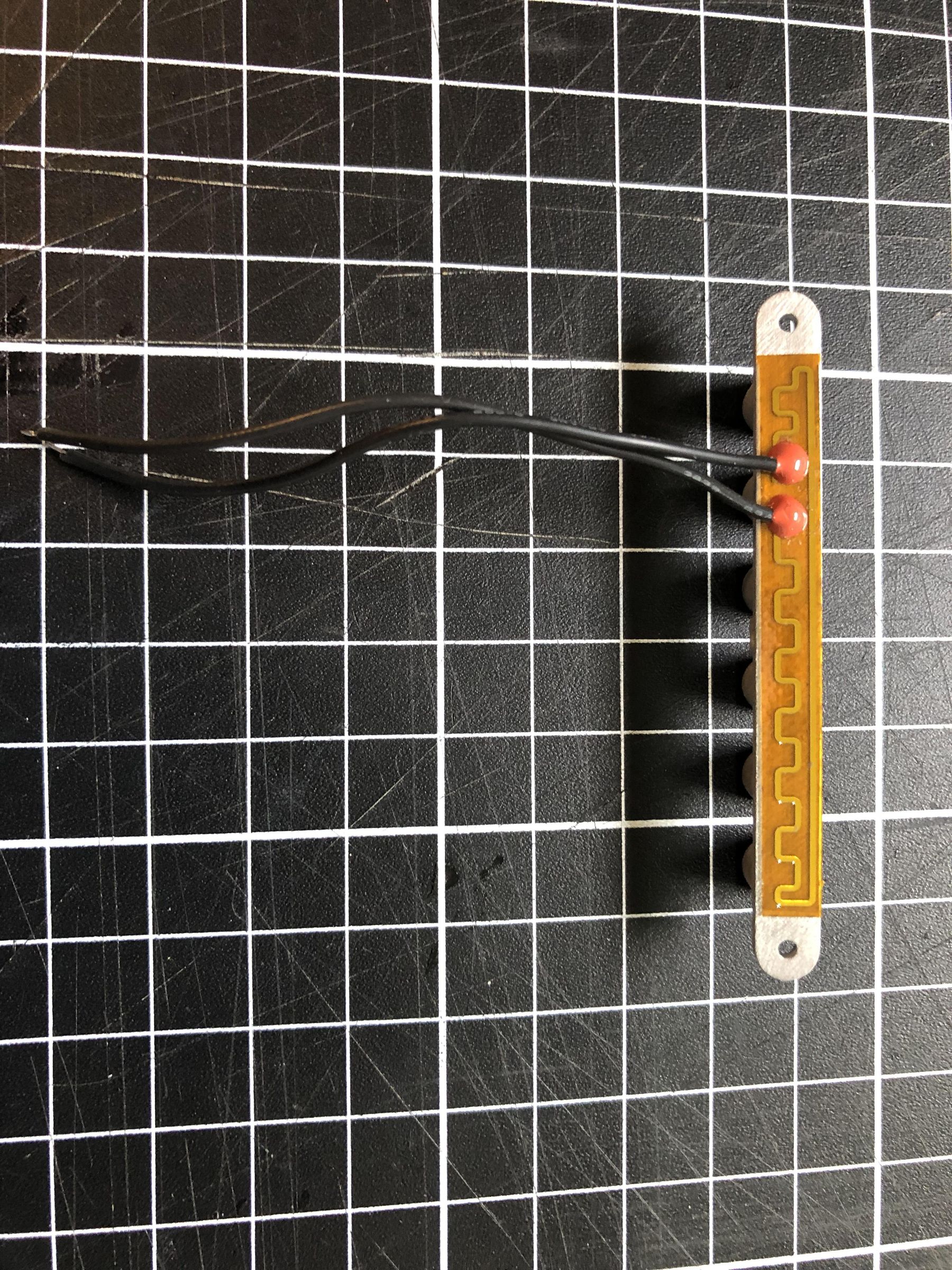
First, cut the wires on the flexible heating pad to a length of approximately 7 cm, then strip and tin the ends of each wire.
For the best adhesion, lightly sand the underside of the aluminium heat block with fine-grit sandpaper to remove any surface imperfections, then wipe away any dust.
Peel the protective backing from the adhesive on the heating pad and carefully attach the pad to the underside of the heat block. Apply firm, even pressure to ensure good contact between the heating pad and the heat block.
Insert the PT100 Temperature Sensor
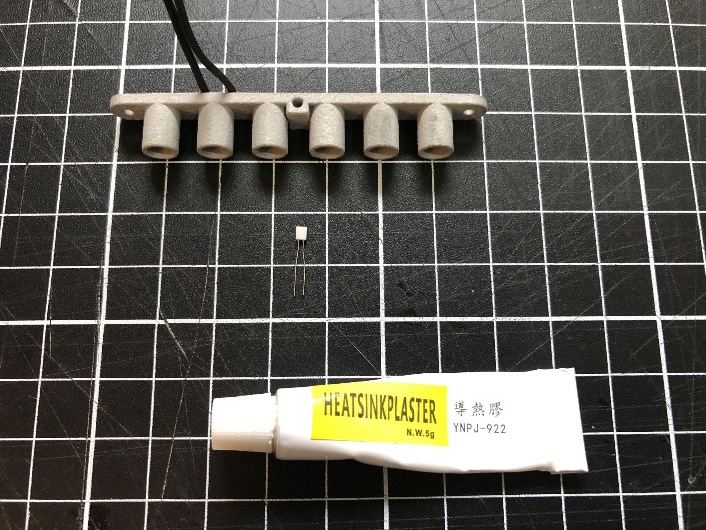
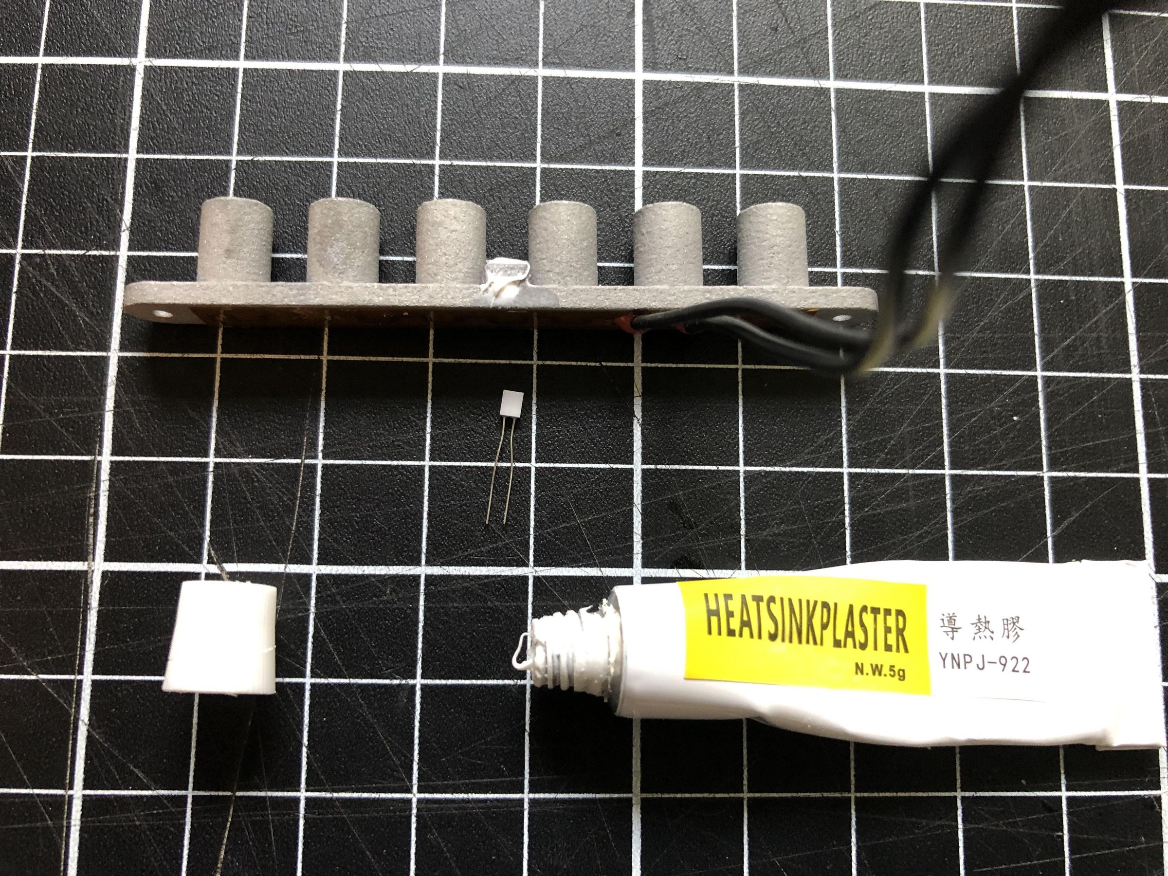
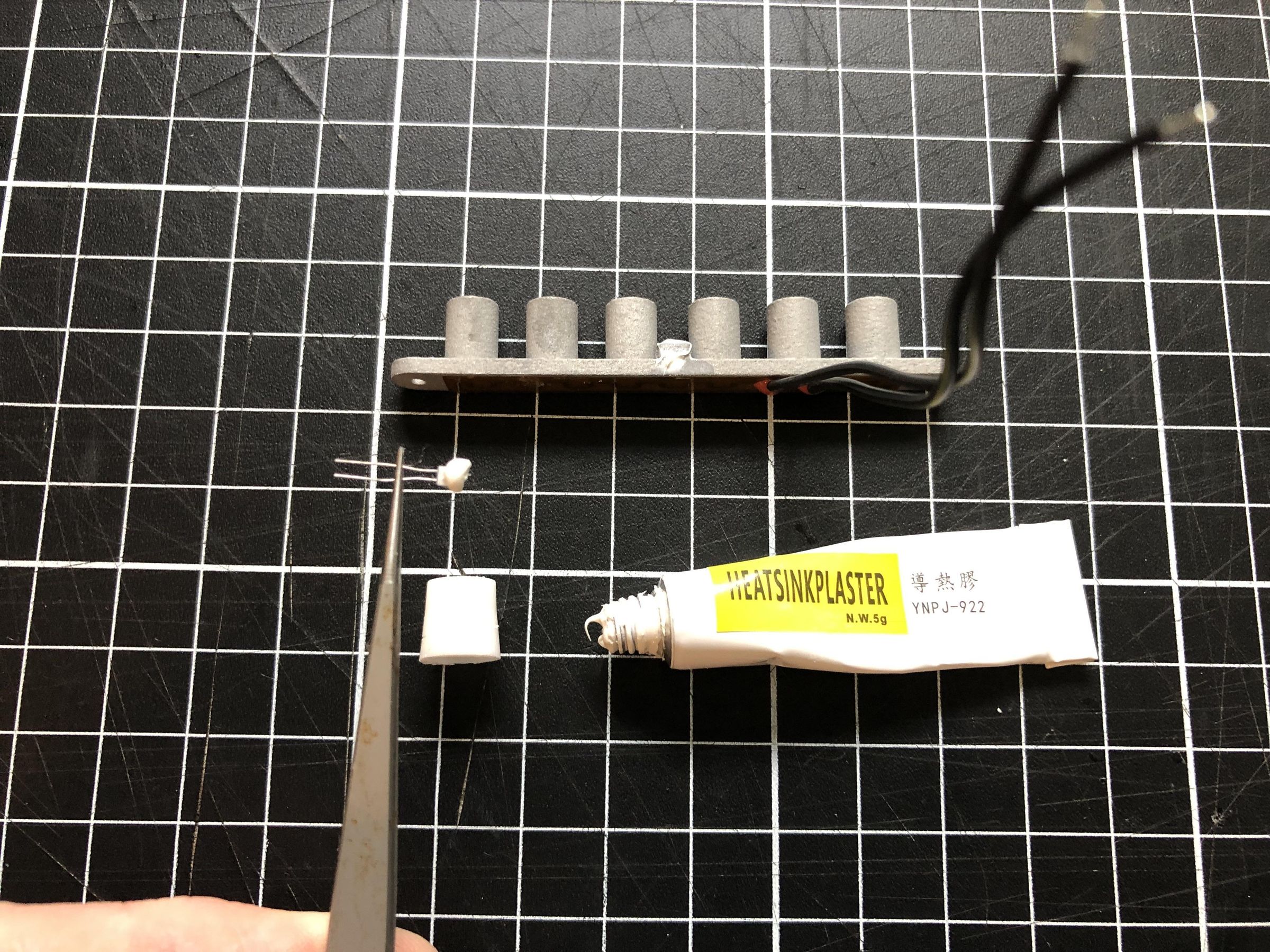
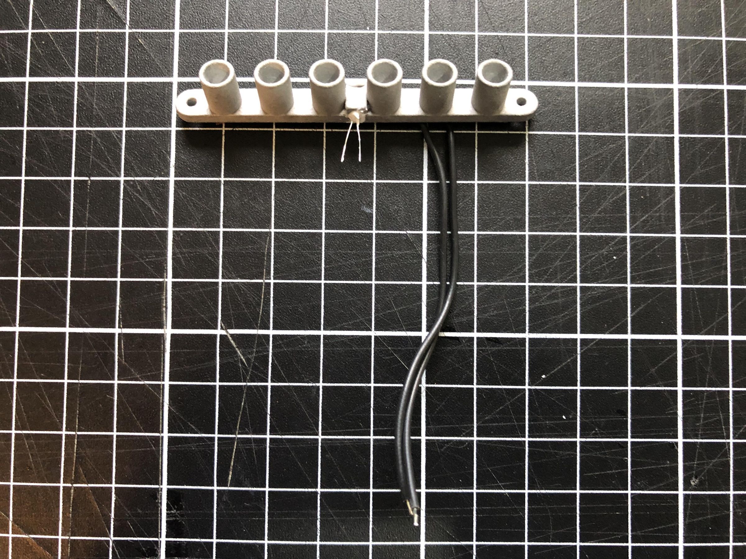
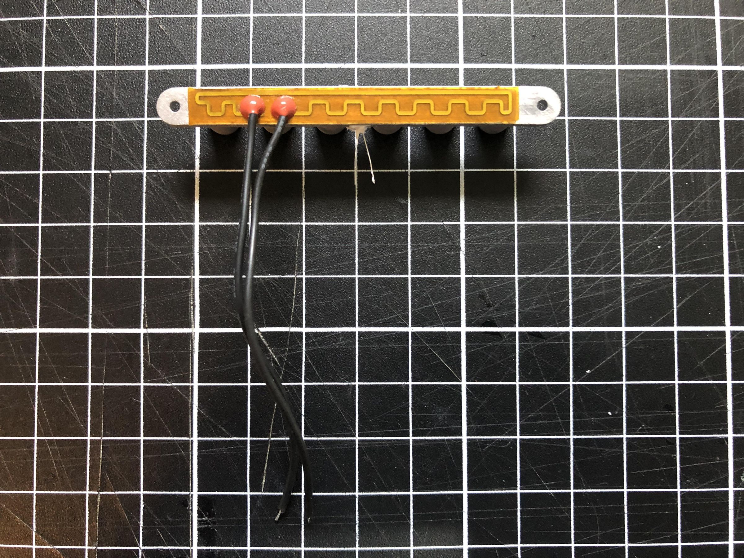
Apply a small amount of thermal paste into the hole in the centre of the heat block. Then apply a thin layer of thermal paste to the PT100 temperature sensor.
Using a pair of tweezers, carefully insert the sensor into the hole until it is fully seated. Ensure that the wires from both the PT100 sensor and the flexible heating pad exit from the same side of the heat block, as shown in the images. This will make routing the wires to the PCB easier during assembly.
Installing the Heat Block
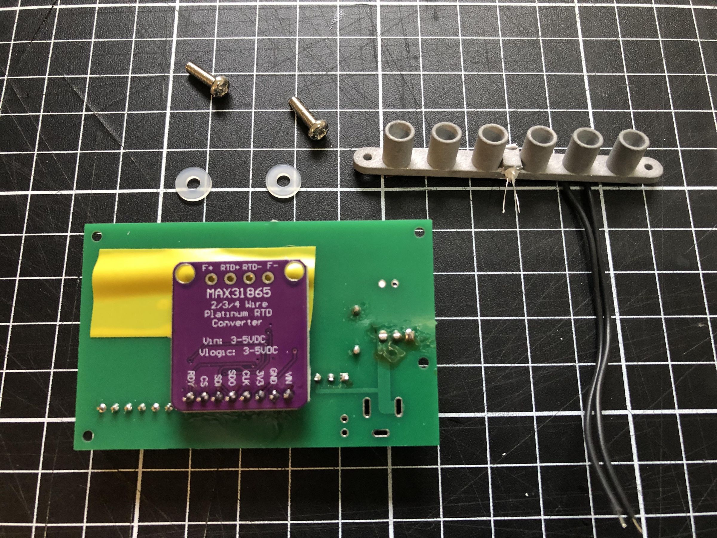
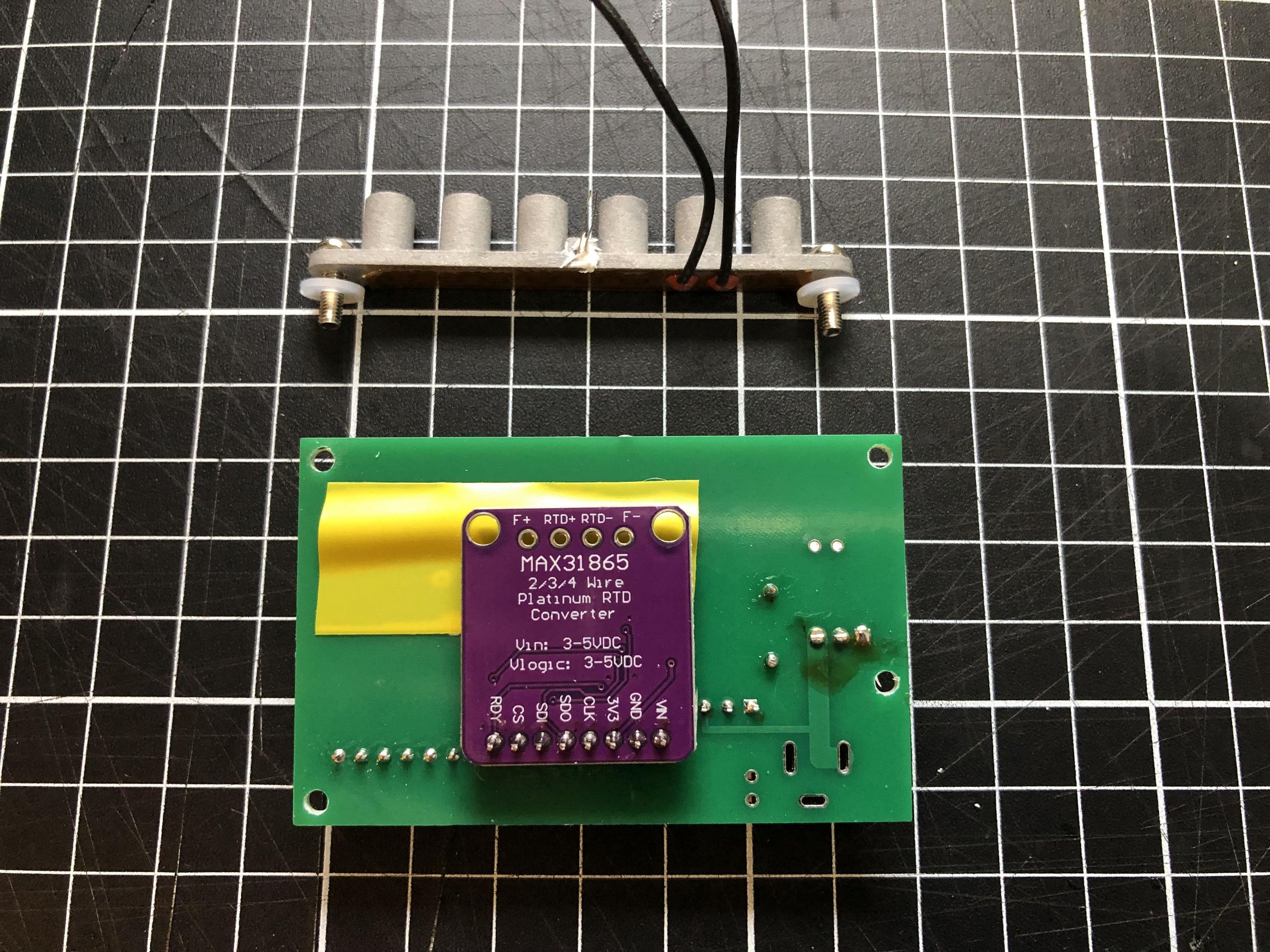
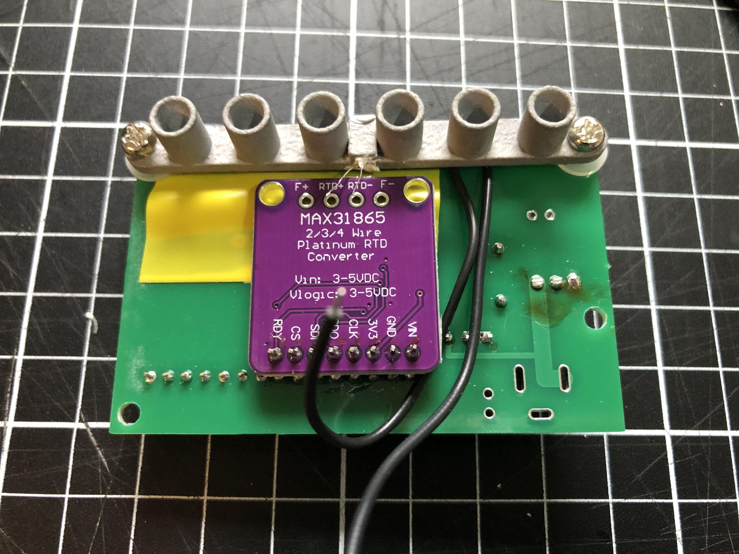
Temporarily install the heat block using two M3 × 10 mm screws. Place a nylon washer between the heat block and the PCB at each mounting point to act as a spacer and provide clearance between the heat block and the PCB.
Connecting the PT100 Sensor to the MAX31865
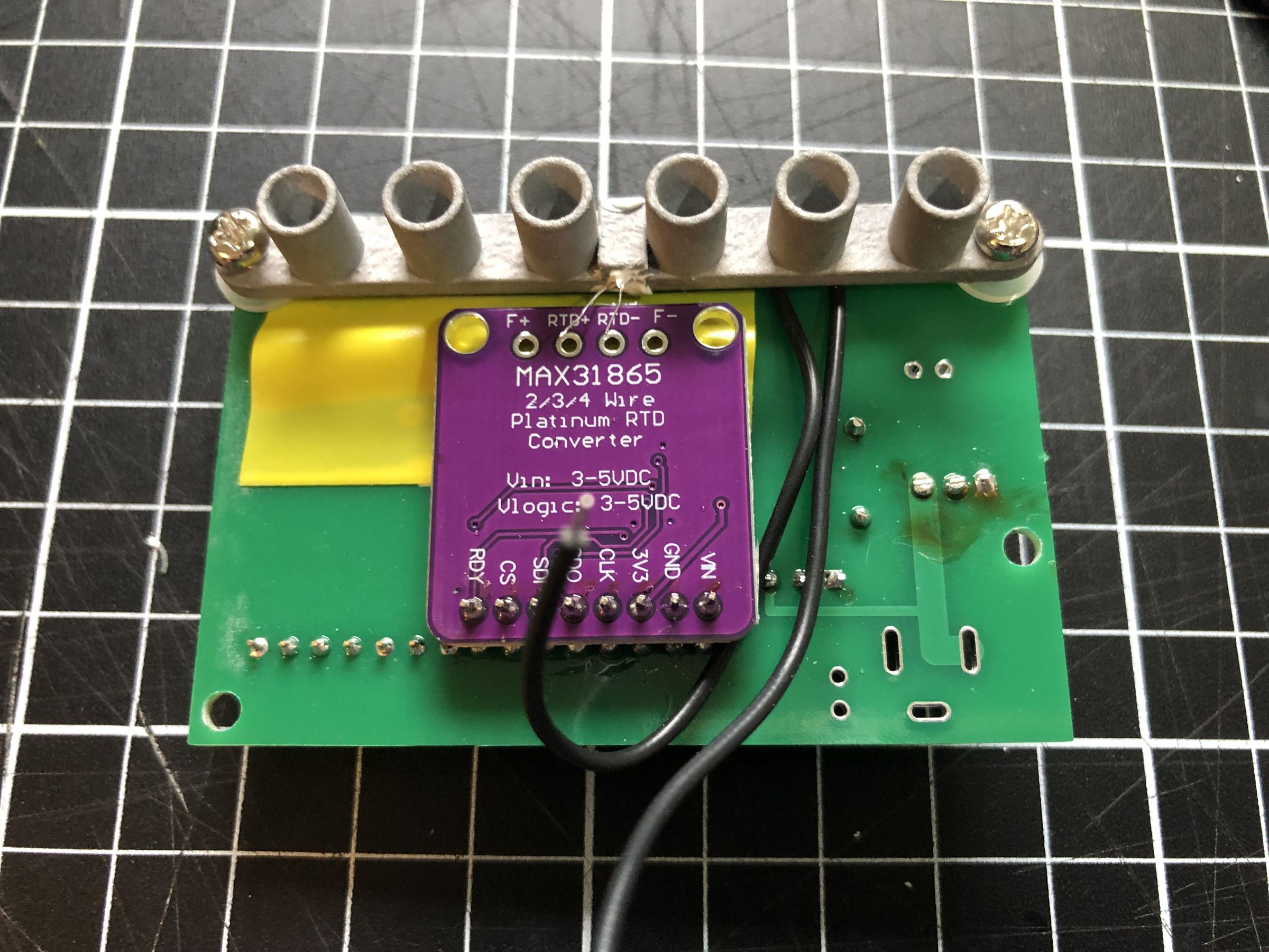
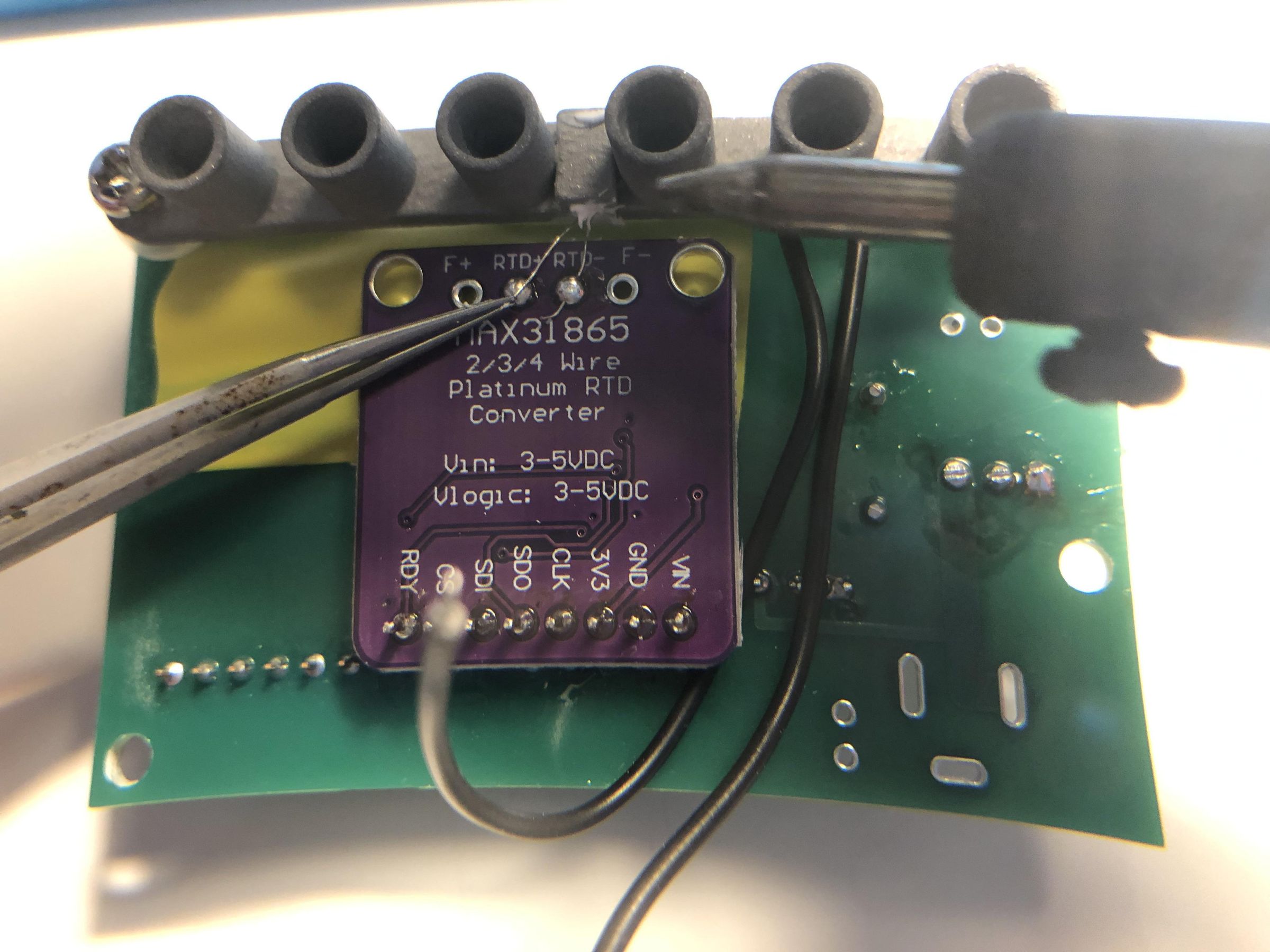
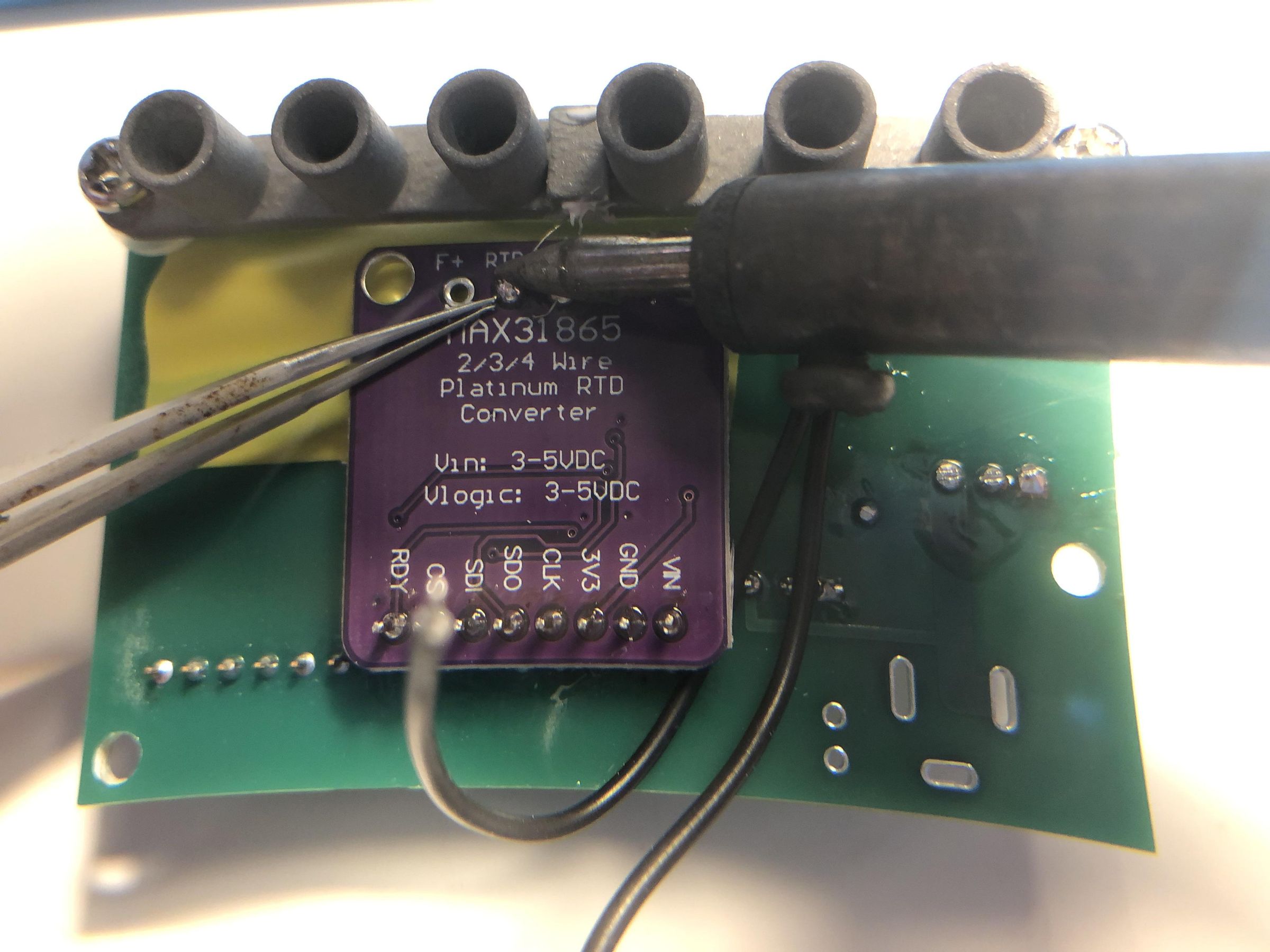
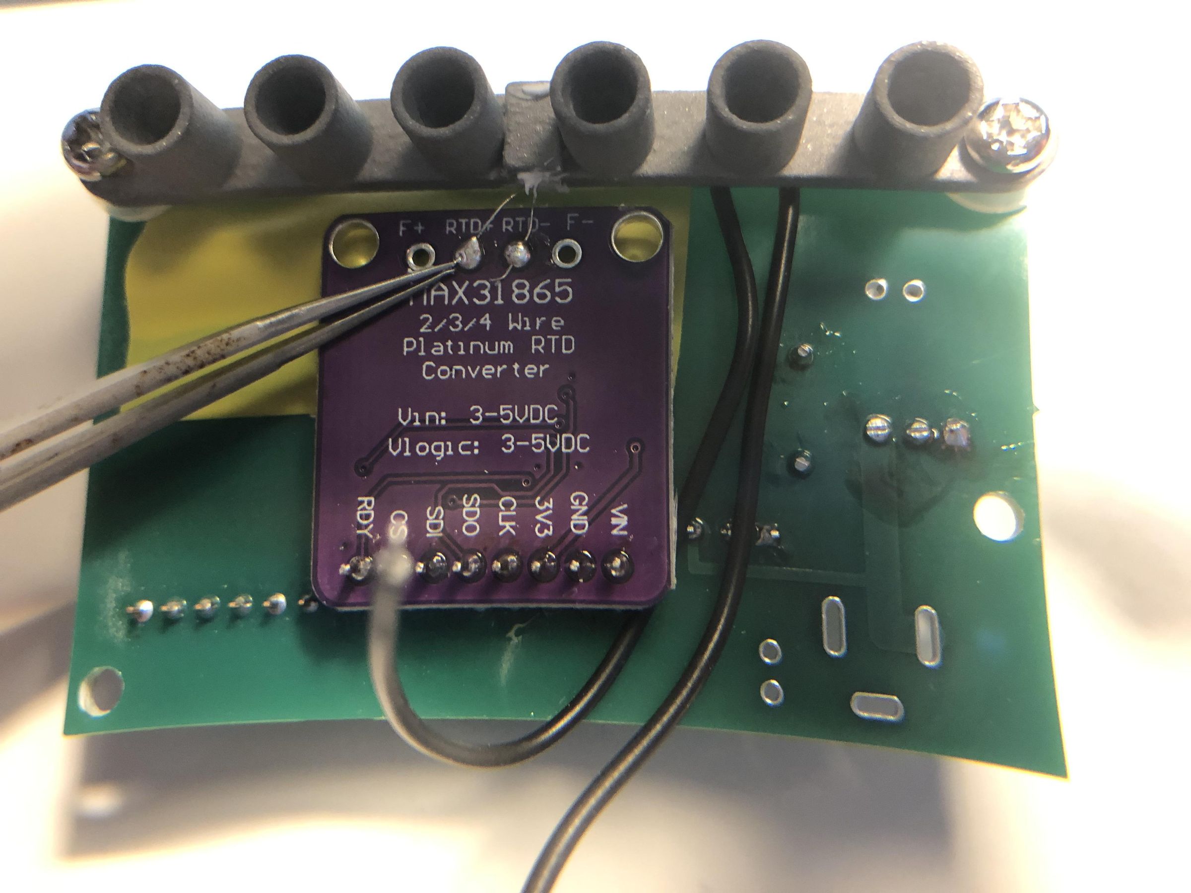
A pair of fine tweezers is extremely helpful for this step.
Carefully solder each of the two wires from the PT100 temperature sensor to the two centre terminals of the MAX31865 module, as shown in the images. Ensure that the solder joints are clean and that there are no solder bridges between adjacent terminals.
Connecting the Fan
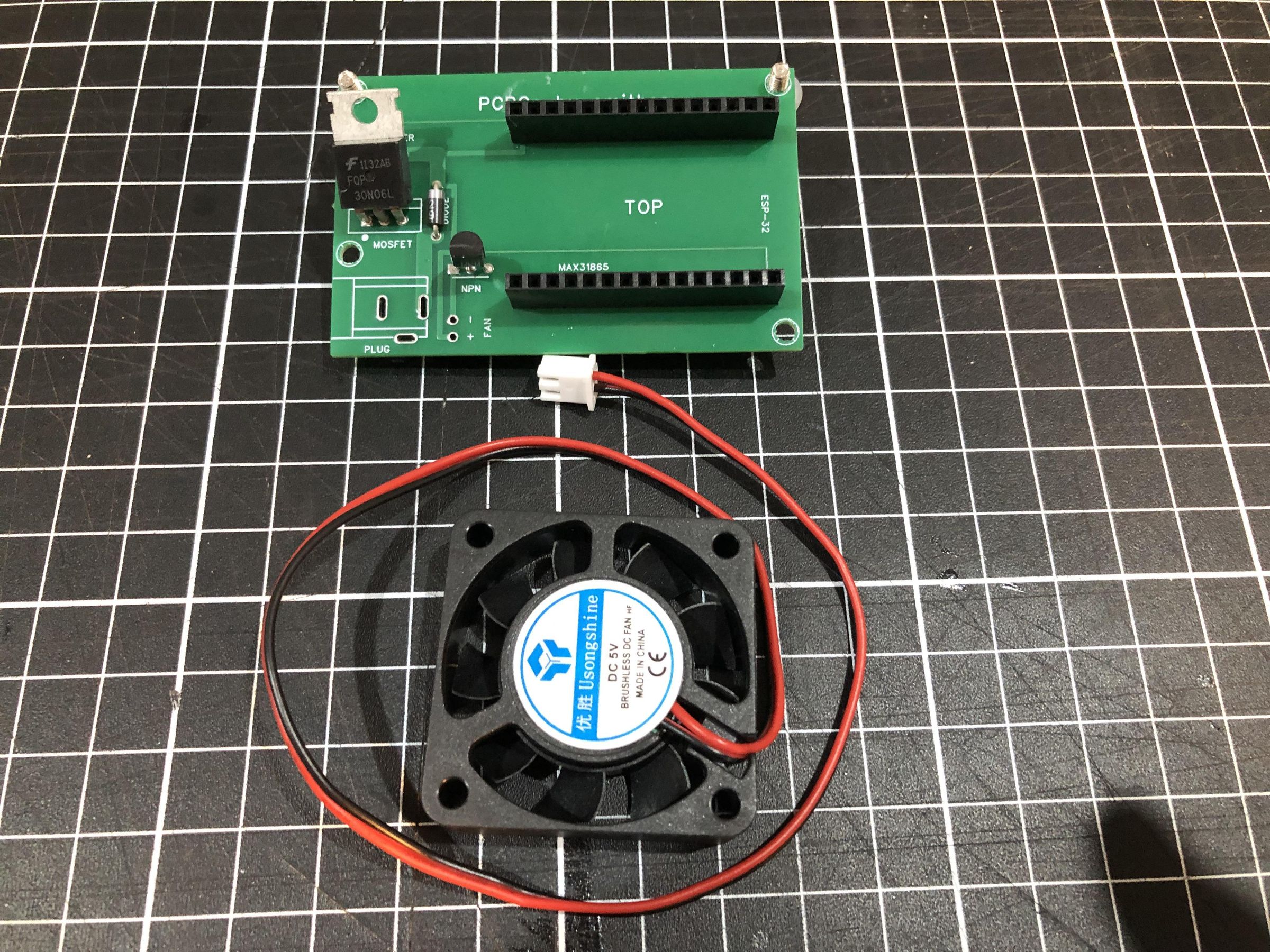
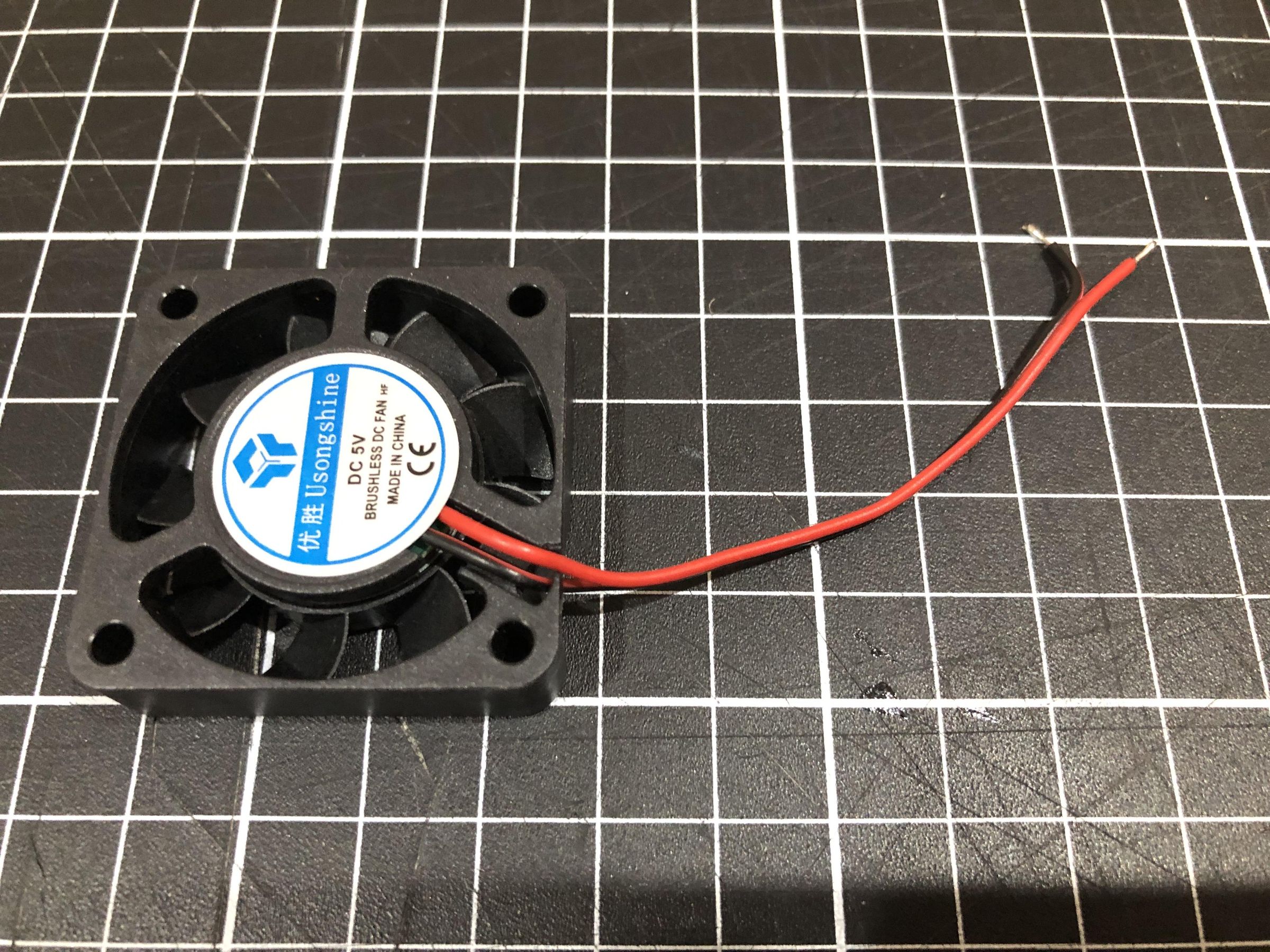
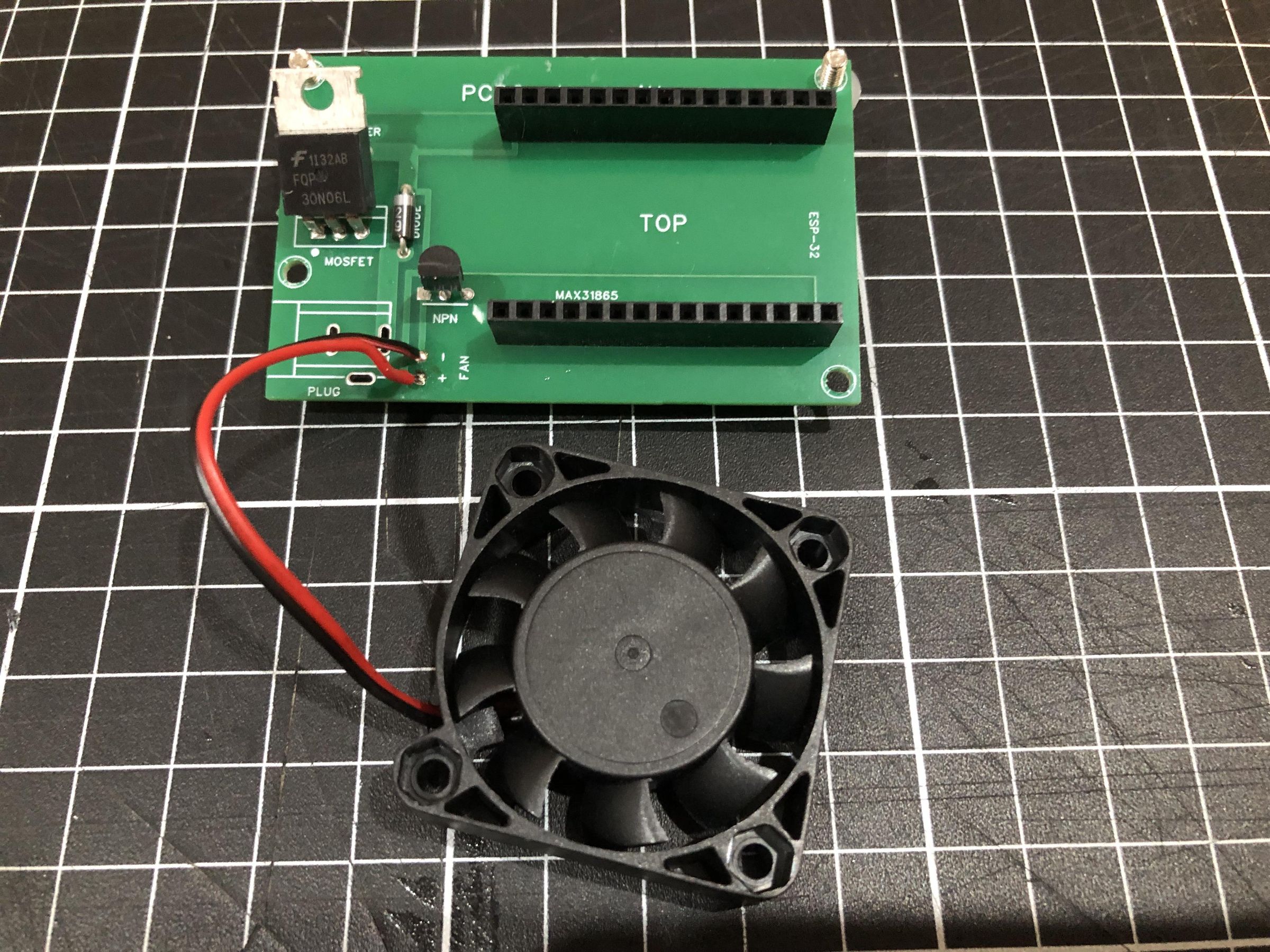
Cut the cooling fan wires to a length of approximately 7 cm, then strip and tin the ends of each wire.
Solder the wires to the PCB at the locations shown in the images, ensuring that the red wire is connected to the positive (+) terminal and the black wire is connected to the negative (−) terminal. Double-check the polarity before soldering, as reversing the connections may prevent the fan from operating correctly.
A Disclaimer About Lithium-ion Batteries
Lithium-ion batteries are capable of supplying very high currents and can become hazardous if they are short-circuited, damaged, overcharged, or discharged below their recommended voltage. Incidents involving damaged lithium-ion batteries have even resulted in aircraft making precautionary or emergency landings.
For the safest operation, I recommend using a 2-cell (2S) battery protection board (BMS). A BMS helps protect the batteries by preventing over-discharge, over-charge, over-current, and short circuits, which can significantly improve both safety and battery life.
To keep PCRGo as simple as possible, I have chosen not to include a BMS in this Instructable. It adds additional wiring and components, and if installed incorrectly it can introduce its own problems. However, I have included links to suitable battery protection boards if you would like to incorporate one into your build.
For safety, always charge your lithium-ion batteries using a quality commercial charger designed for the type of batteries you are using. To minimise the risk of over-discharging the batteries, I recommend recharging them after each PCRGo run rather than repeatedly using them until they are depleted.
If you plan to use PCRGo in the field, take multiple charged sets of batteries with you instead of trying to maximise the run time from a single set. This approach will help extend battery life and reduce the risk of damaging the cells through excessive discharge.
Connecting the 18650 Battery Holder!!!
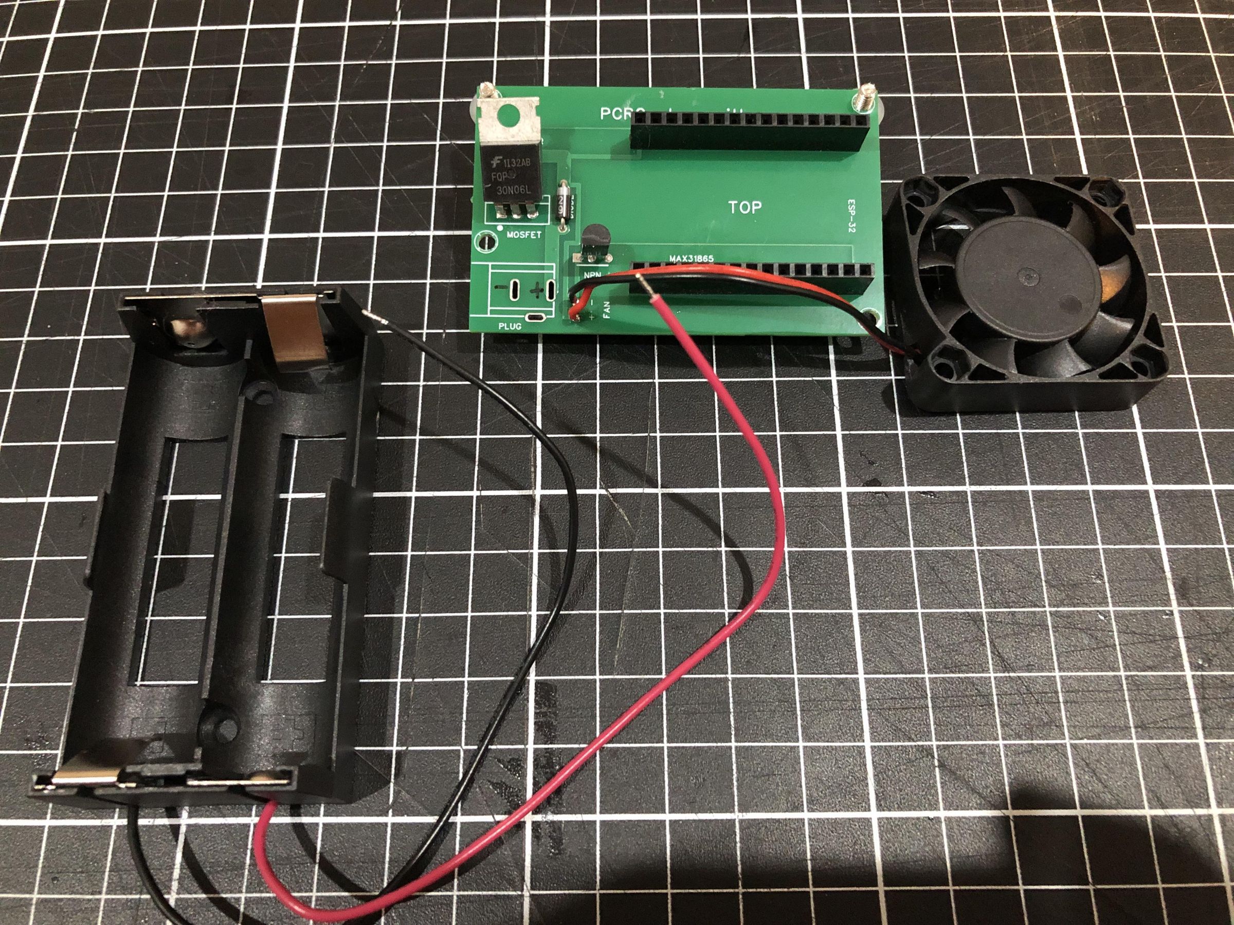
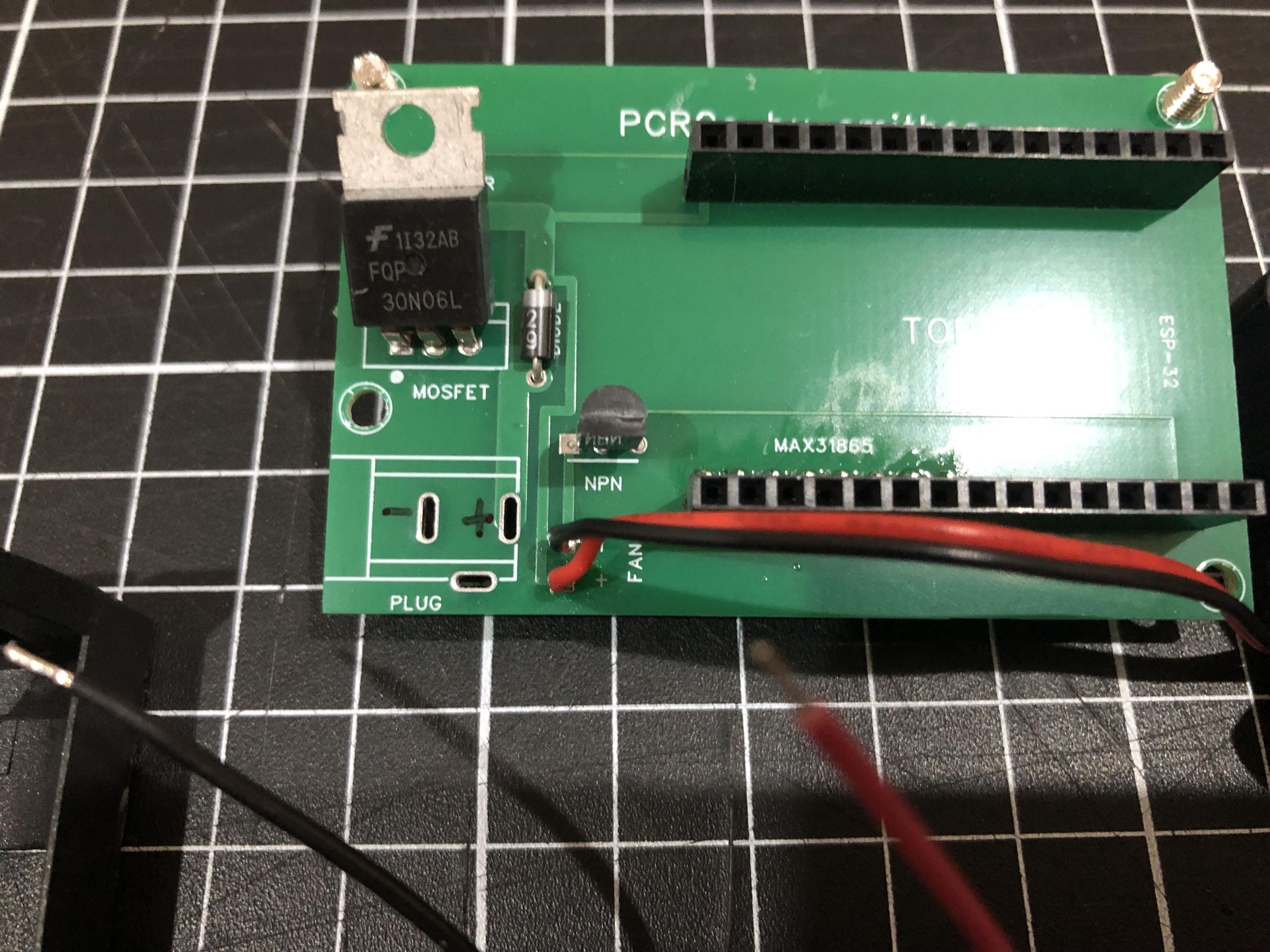
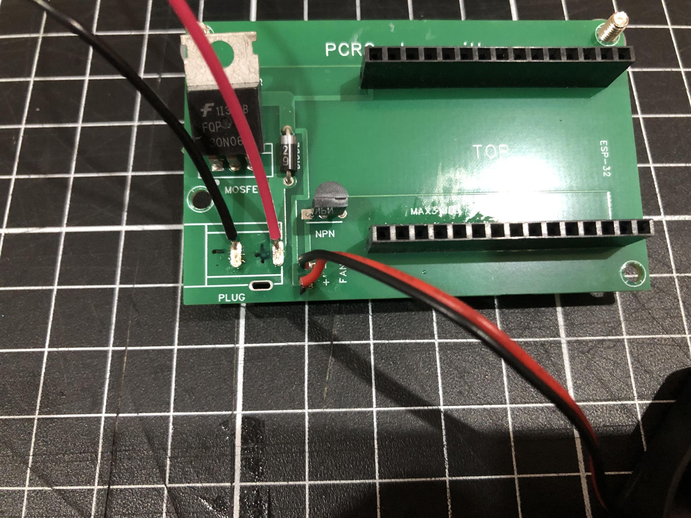
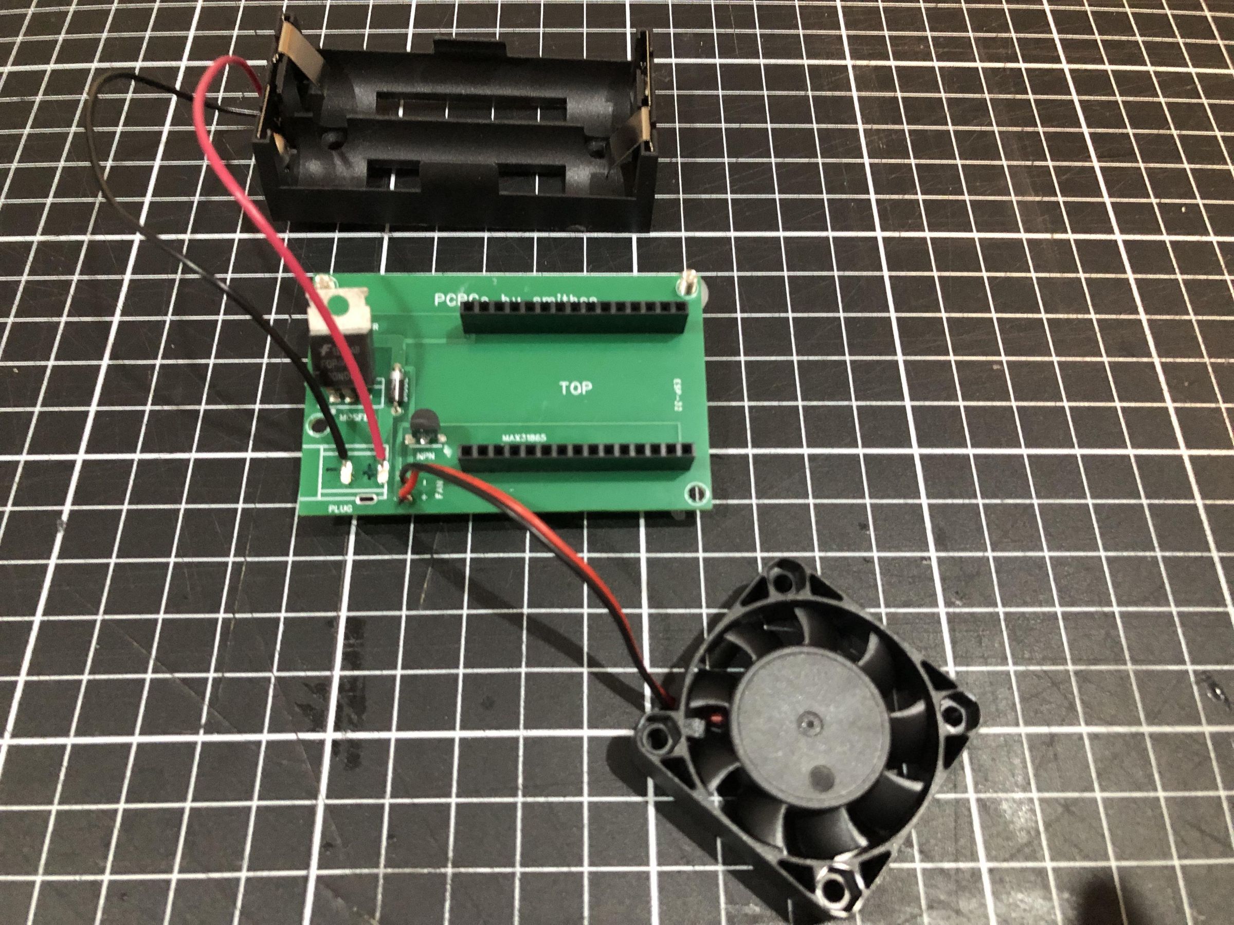
The wires on the battery holder should already be tinned and ready for soldering.
Solder the wires to the PCB at the locations shown in the images, ensuring that the red wire is connected to the positive (+) terminal and the black wire is connected to the negative (−) terminal. Double-check the polarity before soldering, as reversing the connections may damage the PCB or other components.
Programming the ESP32
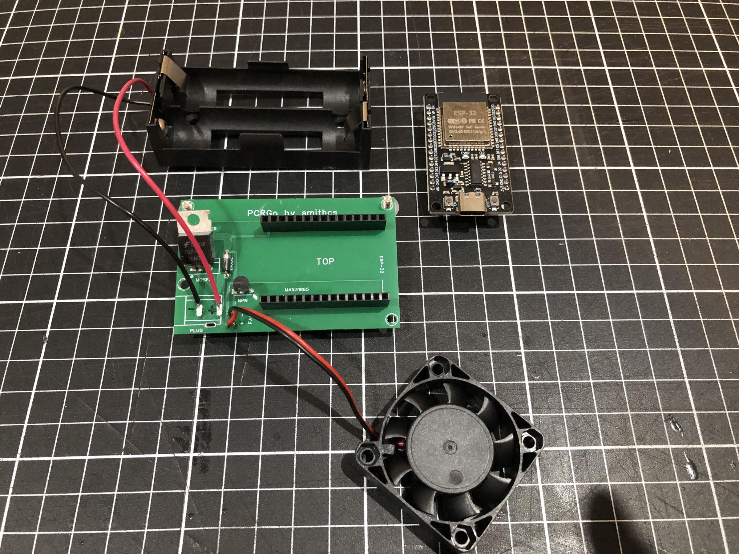
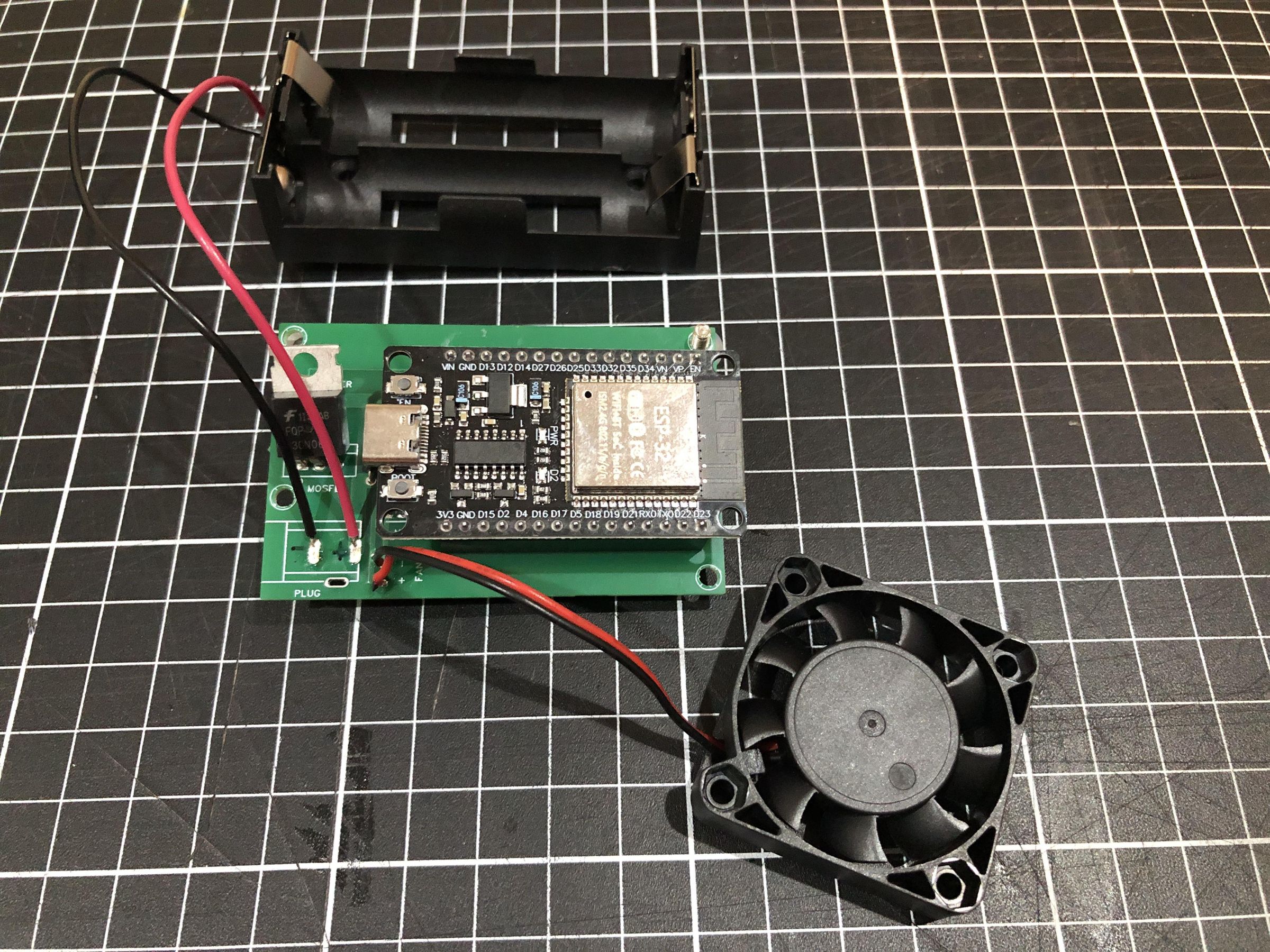
We're now almost ready to install the ESP32 into the sockets on the PCB that we soldered earlier. Before doing so, we need to program it.
Do not program the ESP32 while it is installed in the PCB. The battery pack could inadvertently power the board, and unexpected voltages on the PCB may damage the ESP32, your computer, or the USB port.
Using the Arduino IDE, open the sketch attached to this Instructable and upload it to the ESP32. Before uploading, select ESP32 Dev Module as the target board in the Tools > Board menu.
If you've never programmed an ESP32 before, don't worry—there are many excellent online tutorials that will guide you through installing the Arduino IDE, adding ESP32 board support, and uploading your first sketch.
Once the upload is complete, disconnect the USB cable.
The ESP32 is now ready to be installed into the sockets on the PCB. Carefully check the orientation before inserting it, ensuring that it matches the images. Do not force the board into place. Installing the ESP32 the wrong way around can damage both the ESP32 and the PCB.
Downloads
Powering Up PCRGo for the First Time
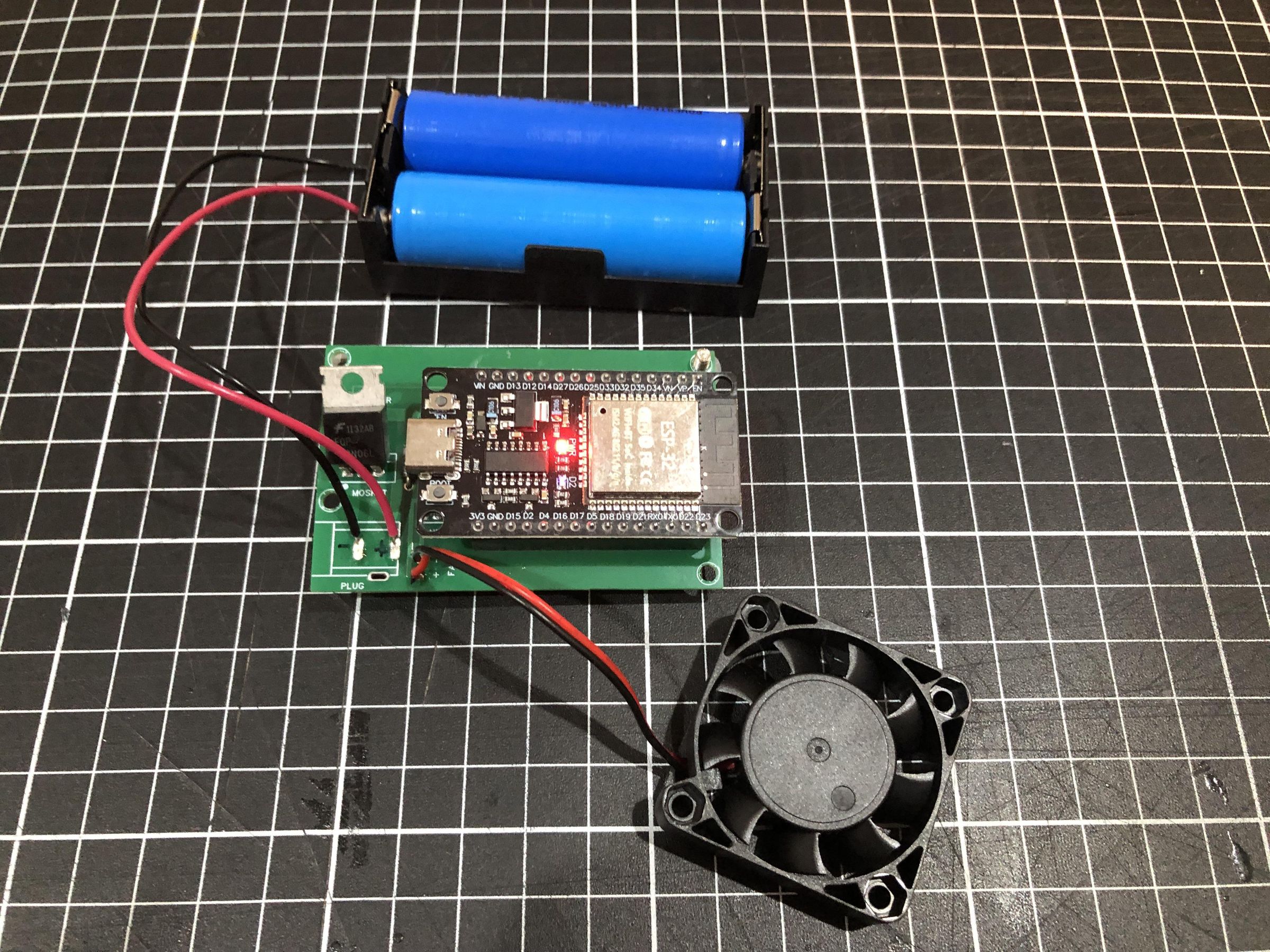
You are now ready to power up PCRGo for the first time.
Insert the batteries into the battery holder, ensuring that they are installed with the correct polarity, as indicated on the holder.
PCRGo includes a Schottky diode that helps protect the electronics if the batteries are accidentally inserted with reverse polarity. However, this protection is not foolproof. Incorrect battery installation may still damage the batteries, wiring, or other components, so always double-check the battery orientation before applying power.
When power is applied correctly:
- The red LED should illuminate, indicating that power is present.
- The blue LED should also flash, indicating that the ESP32 is running and ready to communicate.
If you have already installed the RemoteXY app onto your device, you should now be able to connect to PCRGo as described earlier in this Instructable.
Final Assembly
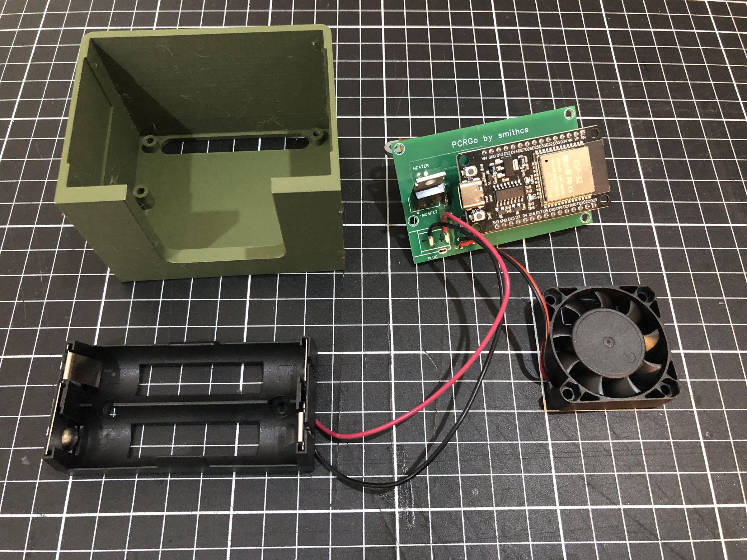
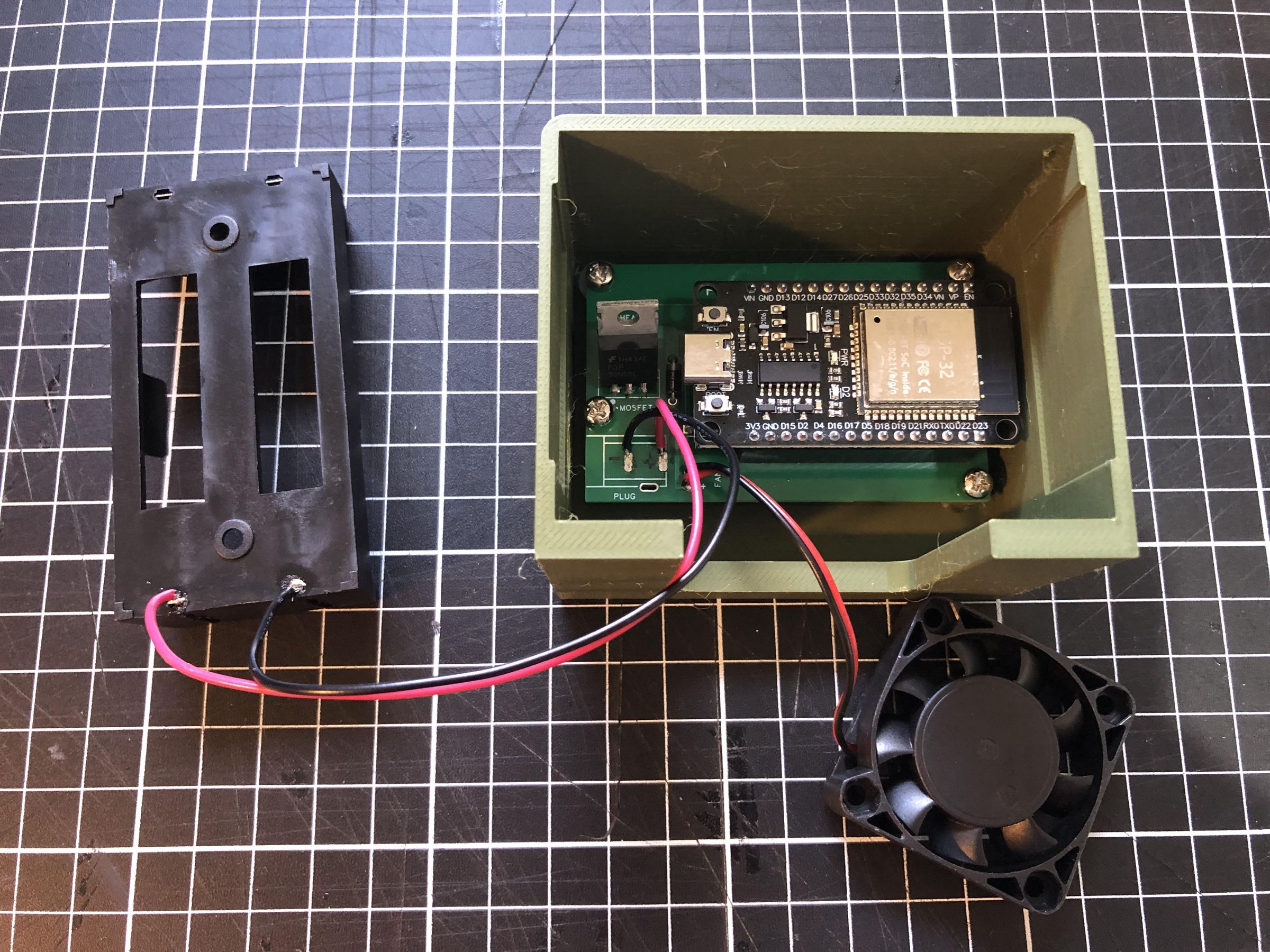
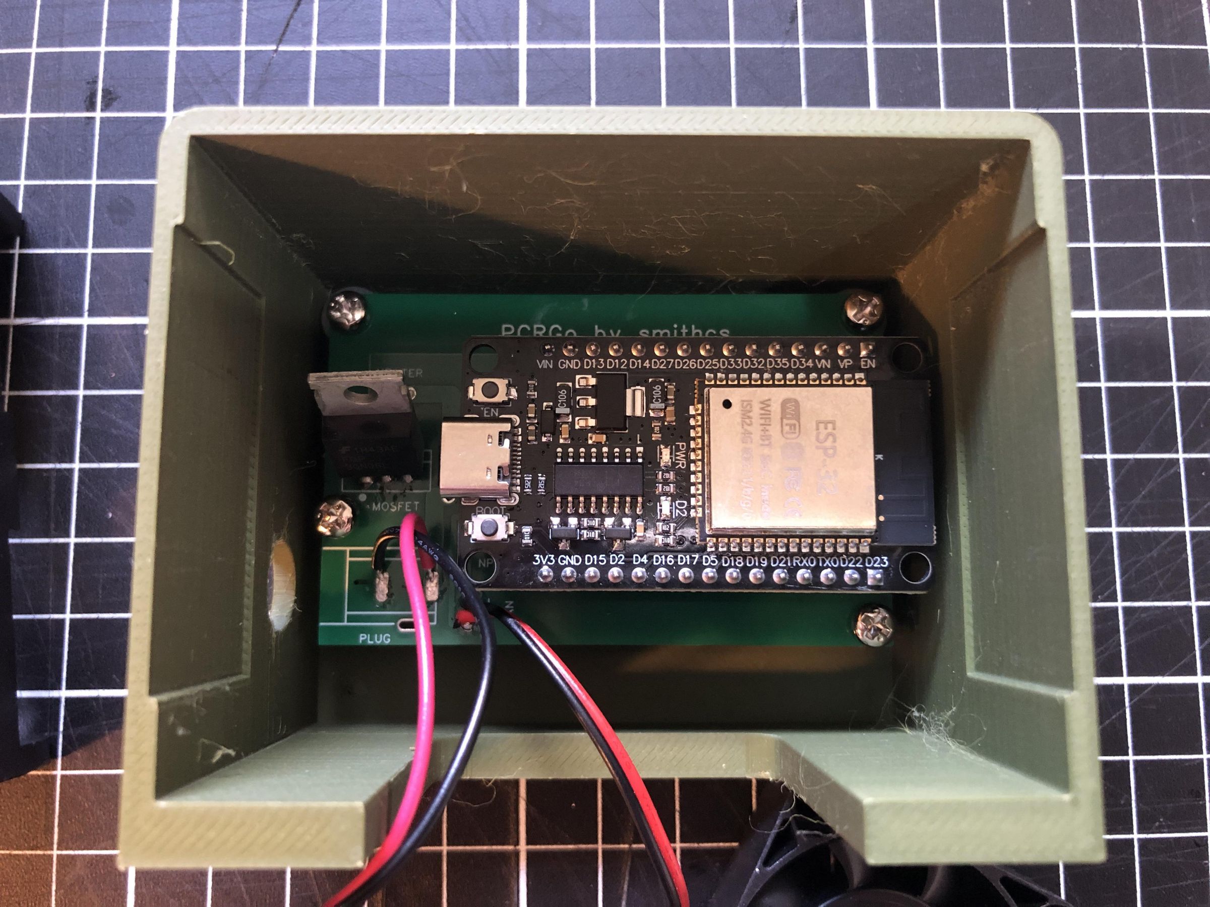
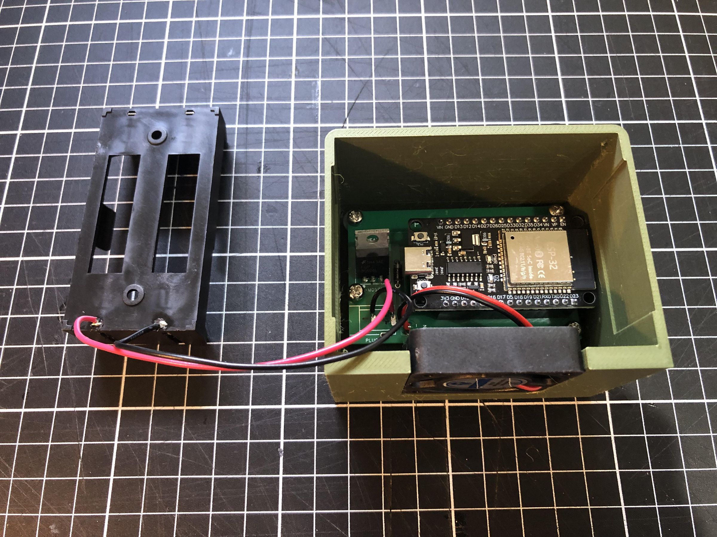
Now that you've completed construction of your PCRGo, it's time to install it into its case.
Download the PCRGo case from MakerWorld and print it using PETG filament. PLA can also be used, but PETG is recommended if PCRGo will be used outdoors or in warmer environments due to its improved heat resistance and durability.
Remove the M3 × 10 mm screws that were temporarily securing the heat block. Reinsert the screws from the opposite direction, ensuring that the nylon washers remain between the heat block and the PCB to maintain the correct spacing.
Carefully lower the PCB assembly into the case and secure the heat block by tightening the M3 × 10 mm screws.
Finally, use two M3 × 6 mm screws to secure the PCB to the enclosure using the remaining mounting holes. Take care not to overtighten the screws, as this may damage the PCB or the 3D-printed enclosure.
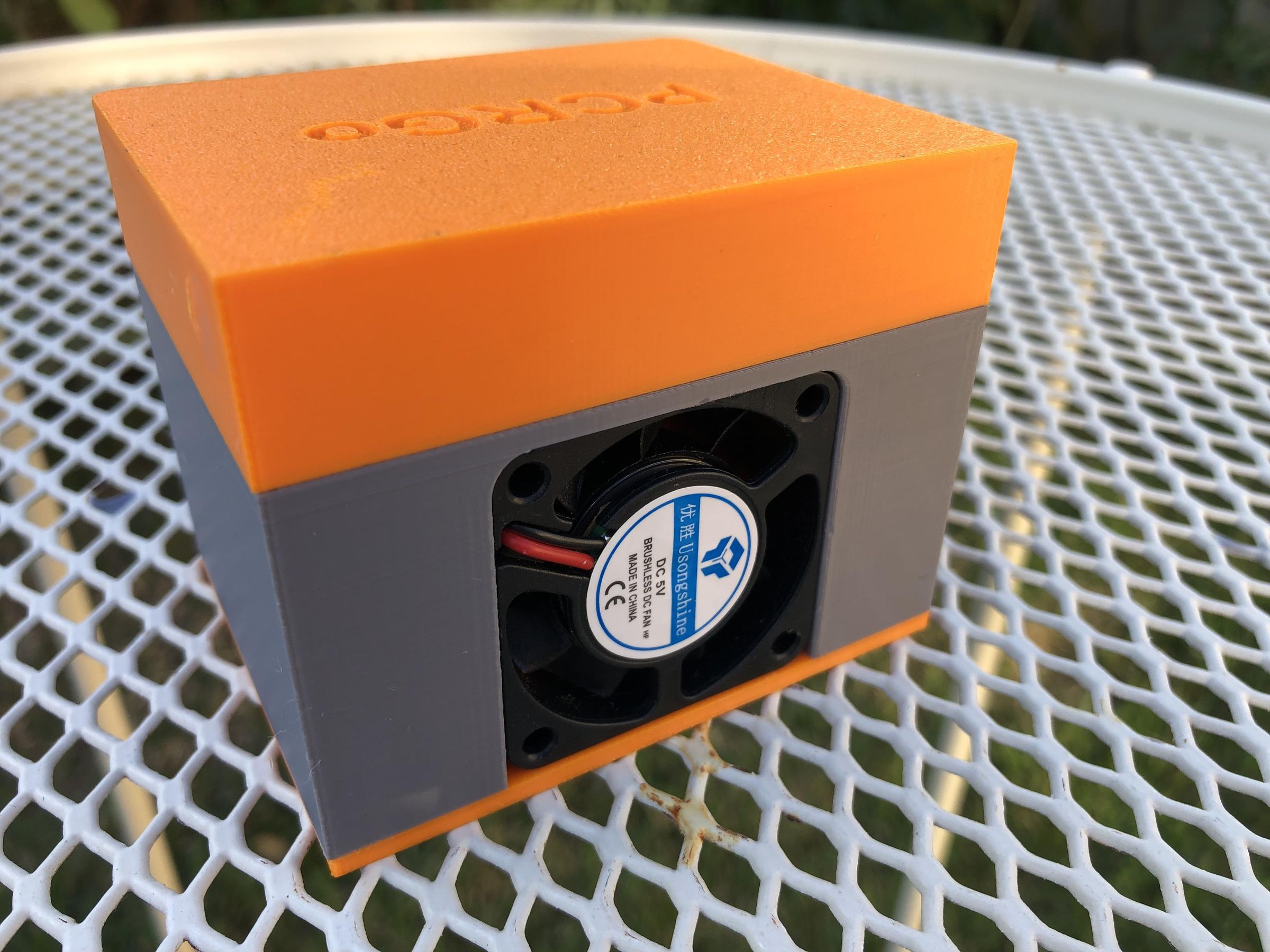
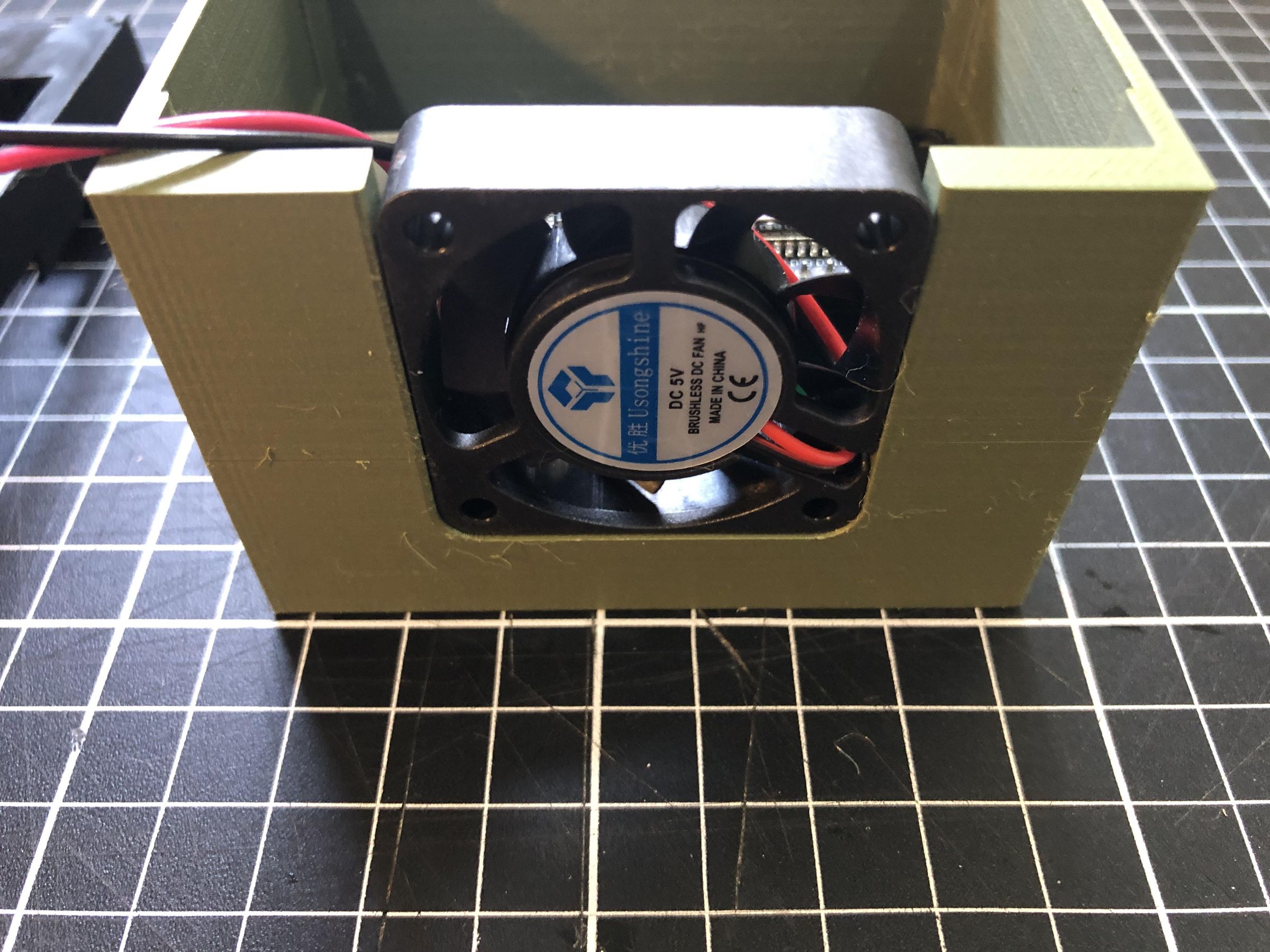
Place the cooling fan into the enclosure with the label facing outward, as shown in the images. This orientation ensures that air is drawn in over the heat block and exhausted through the rear of the enclosure, providing effective cooling.
The fan should be a snug fit in the enclosure. If necessary, apply a few small drops of cyanoacrylate (super glue) to secure it in place. Take care not to allow any adhesive to enter the fan or contact the blades, as this may prevent the fan from operating correctly.
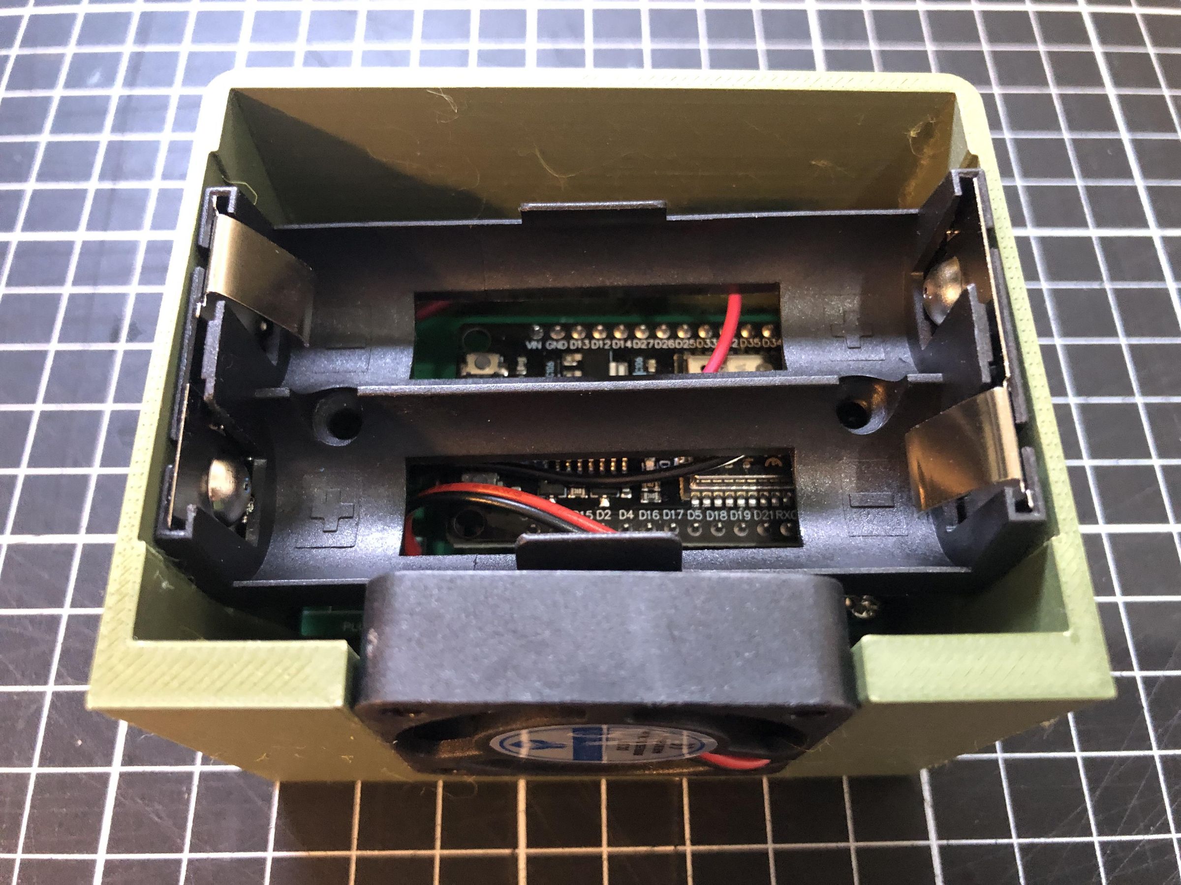
Finally, insert the battery holder into the enclosure. The fit is intentionally loose to make installation and removal easier.
If you prefer a more secure fit, you can apply a few small drops of super glue to hold the battery holder in place. Alternatively, insert a small piece of cardboard or other thin packing material alongside the battery holder to create a snug friction fit without using adhesive.
Completing the Case
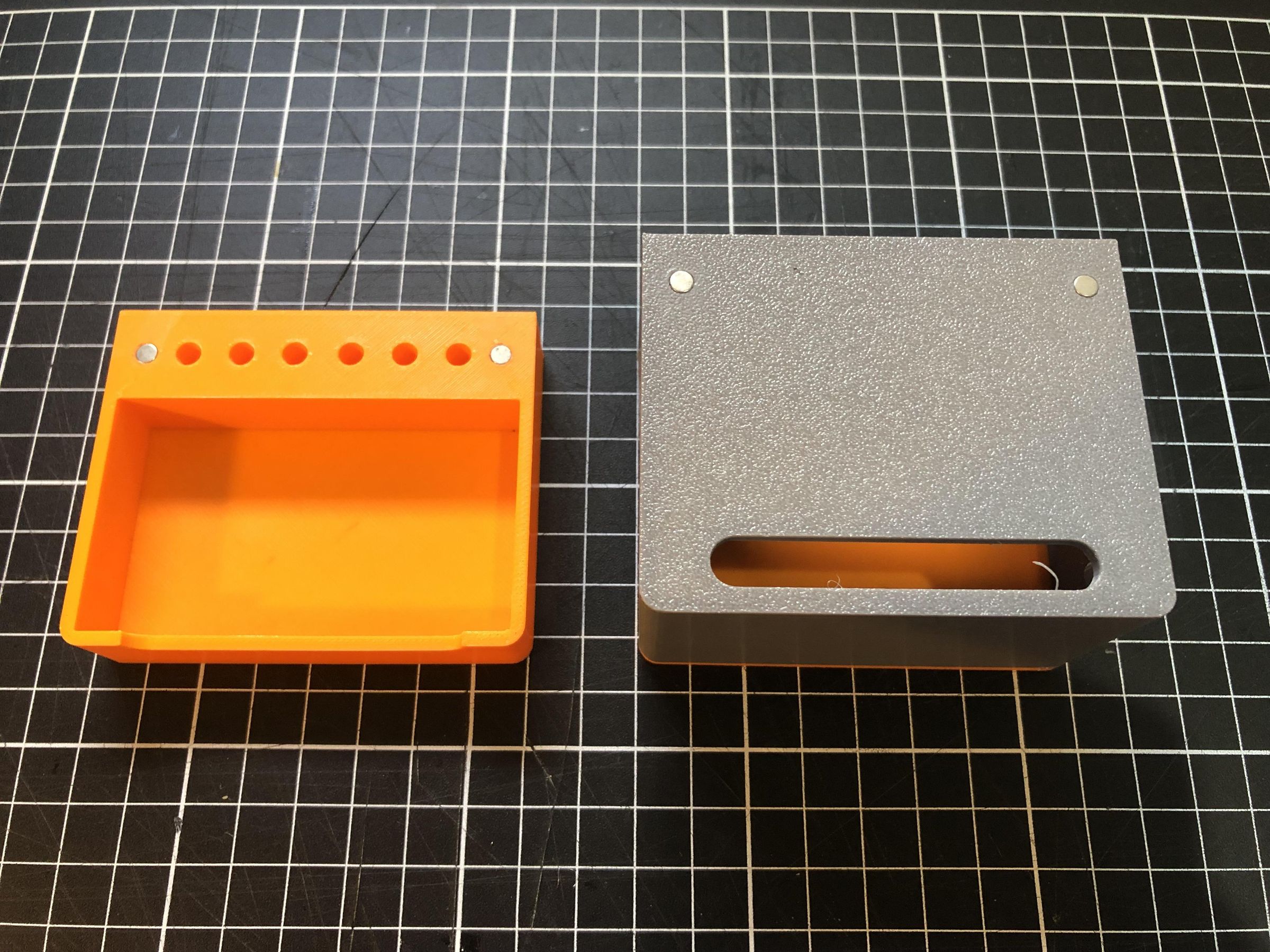
Next, click the base into the bottom of the enclosure until it snaps securely into place. Do not use super glue for this step, as you will need to remove the base to access and replace the batteries.
Finally, glue the magnets into the recesses in the top of the enclosure and in the lid using a small amount of super glue. Before gluing, check that the magnets are correctly oriented so that the lid is attracted to the enclosure rather than repelled.
Allow the adhesive to cure completely before placing the lid onto the enclosure. This will prevent the magnets from shifting position while the glue is still setting.
Also, did you notice, if you turn the lid upside down it doubles as a tube rack!
Final Thoughts
If you decide to build your own PCRGo, I'd love to hear how it goes! Please share photos of your finished build and let me know what you're using it for. Your feedback will help improve future versions of PCRGo and may inspire others to build one too.
If you have any ideas for improving the hardware, enclosure, or software, or if you make your own modifications, please share them in the comments. I'd be delighted to see how the design evolves.
During my PhD, I spent a great deal of time conducting field work, and I often wished I had a battery-powered thermal cycler that I could take with me. It's taken years of experimenting, designing, and refining, but I finally have a design that works. I hope PCRGo helps make molecular biology more accessible and proves useful for students, teachers, researchers, and citizen scientists alike.
Happy building, and happy amplifying!