PEACE Badge


Flags and symbols can unite but also divide people. My favorite flag is the peace flag in the version of the 7-color rainbow flag. An original way to show your support for peace and for diversity is to display a light that displays the 7 colors of the peace flag in sequence.
Here I show how to make a super-compact light that can be worn or your cloth, the effect is unique, especially for an event in the evening.
The project is based on the Arduino platform, but the final project is made with the smaller version of the microcontroller from the same series, the 8-pin ATTINY13A.
Supplies
Arduino Uno microcontroller with prototype shield
ATTINY 13 microcontroller in DIP8 version
An 8-pin DIP socket
A common cathode 5mm RGB LED
An on/off switch
A CR2032 coin cell 3V battery
A battery holder for CR2032
6x28 hole prototype board
Arduino Version


First try it out on an Arduino: upload the attached sketch with the Arduino IDE. I used version 1.8.10. The compiler tells me
Sketch uses 620 bytes (1%) of program storage space. Maximum is 32256 bytes.
Global variables use 10 bytes (0%) of dynamic memory, leaving 2038 bytes for local variables. Maximum is 2048 bytes.
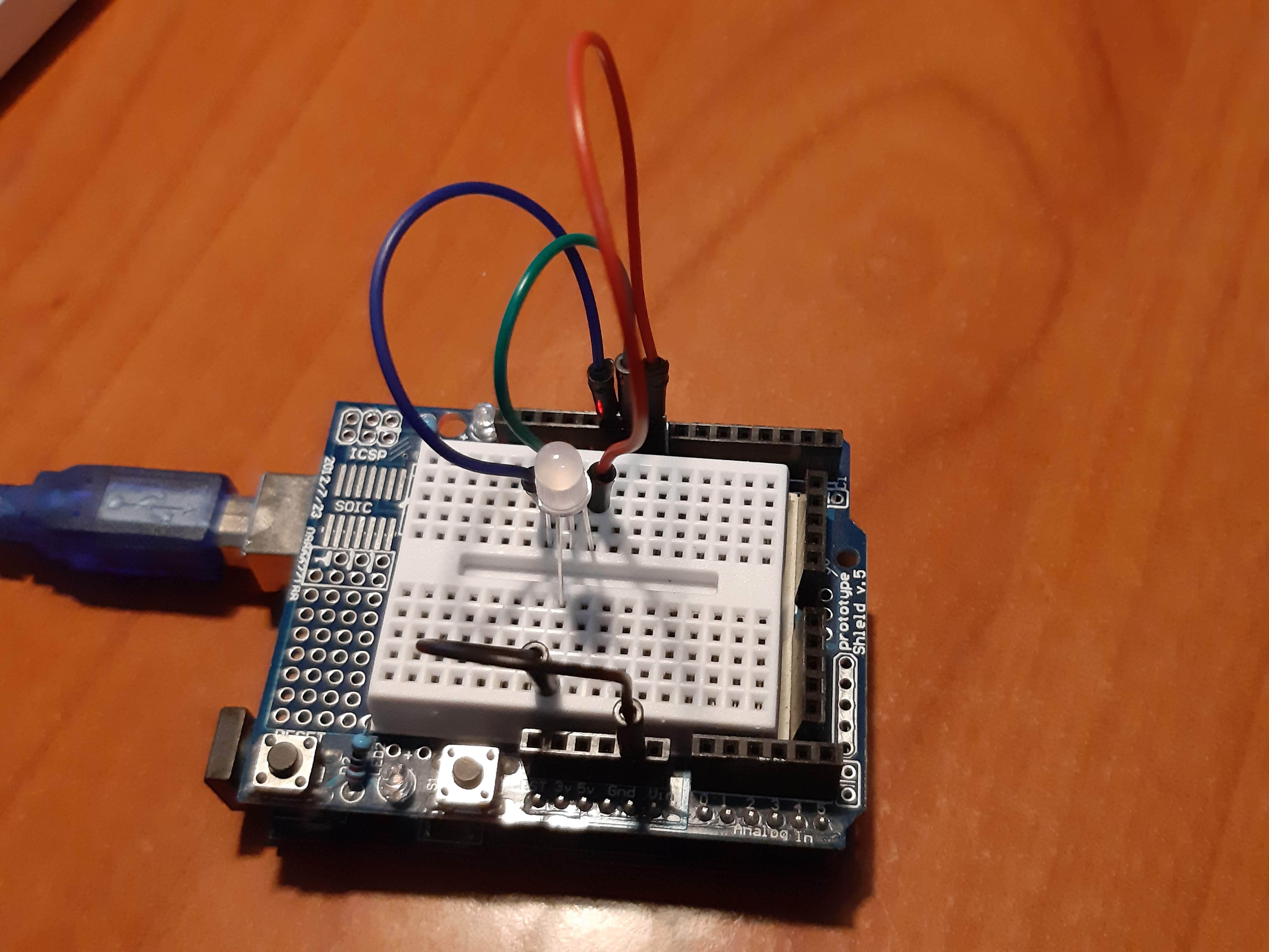
Place the RGB LED on the prototype shield. Connect the common cathode to ground and the pins for red green and blue to the Arduino pins D8, D9 and D10. There is no need for current-limiting resistors: the code uses pulse-width-modulated (PWM) signals which reduce the current sufficiently.
The pin layout of the RGB led can be found as follows: the common cathode is the long pin. The pin order is red, ground, green, blue, from left to right or right to left depending on the orientation of the LED.
Power up the Arduino, and the LED should go through the color sequence violet, blue, cyan, green, yellow, orange, red, followed by no light, with ~1 second per step. If colors come up in a different order, the pins of the LED are probably mixed up. If they come up in the right order but are all a bit too reddish, greenish or blueish, you may need to modify the color calibration in the code, as explained in the next step.
Downloads
Optional: the Code Explained Line-by-line
The code for this project is less than 100 lines and easy to modify or personalize. It has been written such that only one line needs to be changed between the Arduino and the ATTINY13. For those interested in coding, it's explained line-by-line, otherwise just skip to the next step!
“#include <avr/pgmspace.h>”
is needed to put the color definitions and the pattern definitions in the program memory instead of in the RAM. It is not really needed for the Arduino, but the ATTINY has only 64 bytes of RAM, so even a very short sequence quickly fills that up.
//pin connections of the RGB LED
#define MASK_R 0B00000001  // D8  on the uno, PB0 on the ATINY
#define MASK_G 0B00000010  // D9  on the uno, PB1 on the ATINY
#define MASK_B 0B00000100  // D10 on the uno, PB2 on the ATINY
This defines the pins for direct port manipulation. Direct port manipulation is much faster than using the ‘DigitalWrite’ function. Fast code means that we can run the ATTINY at a low clock speed, thus reducing power consumption, which is relevant if you run it from a coin cell.
//calibration of relative strength of red, green, blue
#define cal_R 1.0*255
#define cal_G 0.3*255
#define cal_B 0.5*255
For a given current, green comes out much brighter than blue and even brighter than red, so to get balanced colors, we need to adjust: for this LED, good color reproduction was achieved by reducing green by 70% blue by 50%.
//color definitions
#define ncol 10
#define color_BLACK   0
#define color_RED     1
#define color_GREEN   2
#define color_BLUE    3
#define color_YELLOW  4
#define color_CYAN    5
#define color_MAGENTA 6
#define color_WHITE   7
#define color_ORANGE  8
#define color_VIOLET  9
This is just to give names to colors, so that the color definitions and patterns will be more readable.
//definitions of the colors;
const byte rgb[ncol*3] PROGMEM = {
  0.0 * cal_R, 0.0 * cal_G, 0.0 * cal_B, //black
  1.0 * cal_R, 0.0 * cal_G, 0.0 * cal_B, //red
  0.0 * cal_R, 1.0 * cal_G, 0.0 * cal_B, //green
  0.0 * cal_R, 0.0 * cal_G, 1.0 * cal_B, //blue
  1.0 * cal_R, 1.0 * cal_G, 0.0 * cal_B, //yellow
  0.0 * cal_R, 1.0 * cal_G, 1.0 * cal_B, //cyan
  1.0 * cal_R, 0.0 * cal_G, 1.0 * cal_B, //magenta
  1.0 * cal_R, 1.0 * cal_G, 1.0 * cal_B, //white
  1.0 * cal_R, 0.5 * cal_G, 0.0 * cal_B, //orange
  0.5 * cal_R, 0.0 * cal_G, 1.0 * cal_B  //violet
};
The colors are defined by their relative contribution of red, green and blue. Notice that these are written as floating point numbers, but defined as a ‘byte’, which is an unsigned 8-bit number. The compiler will translate the floating point to byte for the microprocessor.
//definition of the pattern to be displayed
#define nstep 10
const byte patt[nstep] PROGMEM = {
  color_VIOLET,
  color_BLUE,
  color_CYAN,
  color_GREEN,
  color_YELLOW,
  color_ORANGE,
  color_RED,
  color_BLACK,
  color_BLACK,
  color_BLACK,
};
Here is the pattern. The PROGMEM keyword ensures that the pattern is saved in the flash memory instead of in the RAM. Even on the ATTINY13 there is enough space for patterns of several hundred steps.
// this parameter determines the speed
#define steptime 2400  //1s per step on 16MHz Arduino
//#define steptime 180     //1s per step on 1.2MHz ATTINY
On the Arduino, the PWM frequency is about 2400Hz, so letting every step do 2400 cycles will result in a step change every second. To make it step faster through the pattern, reduce this number. To make it go slower, increase this number. On the ATTINY13 at 1.2 MHz, the PWM frequency is reduced to 180Hz. Fast enough to be invisible, but this line will need to be edited.
 void setup() {
  //set LED pins to output and switch them off
  DDRB = (MASK_R | MASK_G | MASK_B);
  PORTB = 0;
}
At setup, which is run once when the Arduino is switched on, all that is needed to be done is to set the relevant pins to OUTPUT, and, just to be sure, the LEDs are switched off.
byte istep = 0;
This is a global variable that keeps track of which step we are in the sequence.
Inside the loop() function, the following is happening:
  //retrieve the color for this step
  byte col =pgm_read_byte_near(patt+istep);
  //find the corresponding intensities of red,green,blue
  byte fr = pgm_read_byte_near(rgb+3*col+0);
  byte fg = pgm_read_byte_near(rgb+3*col+1);
  byte fb = pgm_read_byte_near(rgb+3*col+2);
This is the way to access an array that is stored in the flash memory. First the color, then the corresponding intensity of red, green, blue.
  //light up the red, green and blue channel sequentially
  for (unsigned int i = 0; i < steptime; i++) {
    for (byte icnt = 0; icnt < 255; icnt++) {
      PORTB = MASK_R * (fr > icnt);
    }
    for (byte icnt = 0; icnt < 255; icnt++) {
      PORTB = MASK_G * (fg > icnt);
    }
    for (byte icnt = 0; icnt < 255; icnt++) {
      PORTB = MASK_B * (fb > icnt);
    }
  }
This loop takes about 0.4 milliseconds. First the red channel is lit up for some time, then the green and then the red, with the pulse length determined by the intensities determined for this step. Note that only one LED can be on at a given time. This will reduce current fluctuations in the power supply, and also means that even at maximum intensity a given channel is only on ⅓ of the time. The resulting current for the LED is then small enough that we don’t need to put current-limiting resistors in series with the LED.
  //go to next step
  istep++;
  if (istep >= nstep) istep = 0;
When a step is completed we move to the next. When the sequence is completed it starts over. That’s there is to it!
Moving to the ATTINY.


The Arduino is too bulky to be easily wearable. In fact, the functionality of this project is simple enough that it fits on a much smaller microcontroller. The ATTINY13A is a cheap and readily available alternative. To program it is not as easy as for the Arduino, but no special hardware, software or skills are needed.
There are dedicated instructables on how to program the ATTINY13A. A brief summary is below:
- Starting up the Arduino IDE, open 'Preferences' then add https://mcudude.github.io/MicroCore/package_MCUdud... for additional board managers.
- Under 'Tools/Board', select 'Board Manager' and at the bottom of the list, install 'MicroCore by MCUdude'
- Connect the Arduino Uno and upload 'ArduinoISP'. It is available under 'File/examples'
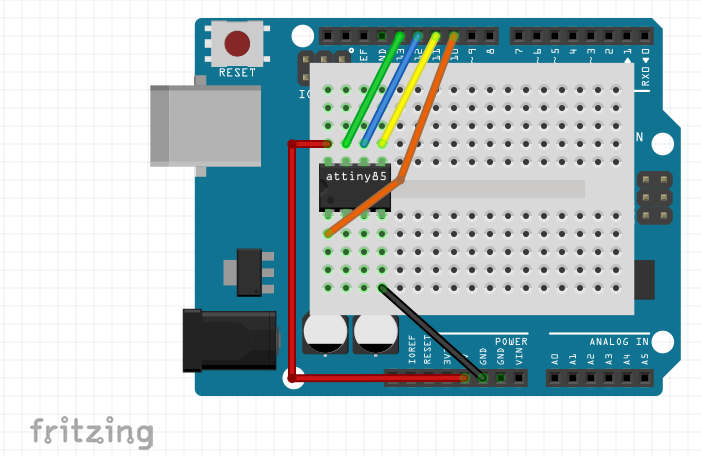
- Connect the Arduino to the ATtiny, easiest done by putting the ATtiny on a prototype shield: Arduino pin 13 - ATtiny pin 7 Arduino pin 12 - ATtiny pin 6 Arduino pin 11 - ATtiny pin 5 Arduino pin 10 - ATtiny pin 1 Arduino +5v - ATtiny pin 8 Arduino GND - ATtiny pin 4
- Choose 'Board ATtiny13', 'B.O.D 2.7V', 'Clock 1.2 MHz internal' and programmer 'Arduino as ISP' (attention: not 'ArduinoISP' but 'Arduino as ISP' )
- Do ‘Burn Bootloader’ - there is no bootloader for the attiny, and it may give an error, but this step is needed to ‘set the fuses’ to the correct clock setting
- Upload the sketch.
Make sure to change the steptime in the sketch from 2400 to 180; line 58/59 should be:
//#define steptime 2400  //1s per step on 16MHz Arduino
#define steptime 180     //1s per step on 1.2MHz ATTINY
The feedback from the compiler is:
Sketch uses 312 bytes (30%) of program storage space. Maximum is 1024 bytes.
Global variables use 6 bytes (9%) of dynamic memory, leaving 58 bytes for local variables. Maximum is 64 bytes.
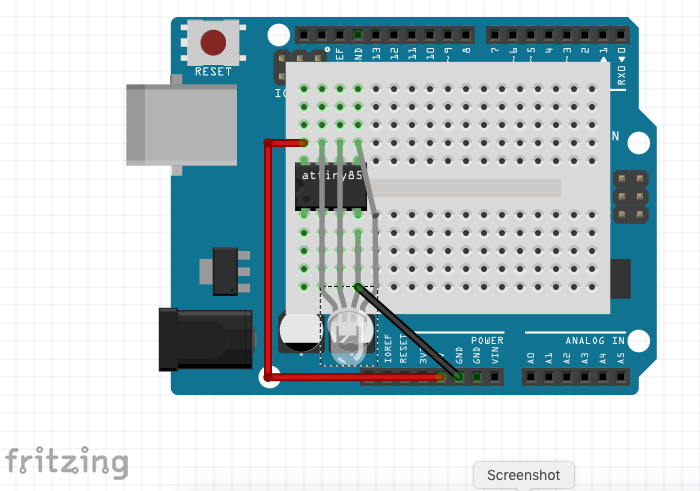
In other words: only one third of the 1kbyte program space is used up, and there is space for patterns of more than 600 steps! Now that the ATTINY has been programmed, rewire to test it: remove all wires except for ground and vcc, and connect the anodes of the RGB LED to pins 5, 6 and 7, and it’s cathode to ground. You should see exactly the same pattern as when it ran on the Arduino. Instead of powering it from the Arduino 5V, power it from a coin cell. The intensity will be lower, but I found the color reproduction just as good.
Making a Badge


Now that the LED runs directly from the ATTINY with a coin cell, it can be make into a wearable badge. First solder the LED, the DIP socket, the switch and the coin cell holder to the prototype board. The LED has the 3 anodes coming in from the up side while the cathode is connected directly to the back of the board. I put a 1cm piece of shrink tube around the anode pin to prevent it from making contact with the cathodes. Next solder all connections, I hope it's clear from the diagram, the schematic and the pictures!
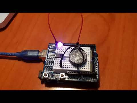
Plug in the ATTINY13 and the coin cell and check if it works. The prototype board can be cut with a boxcutter to the right size. You can wrap the board in fabric or embed it in a hat, a scarf, gloves, but there is a certain aesthetic about wearing it as a bare board: put a ring and a safety pin through one of the holes of the prototype board and it can be worn just like that!