POWER to the People Rechargeable Power Supply for Eurorack
5 Views, 0 Favorites, 0 Comments
POWER to the People Rechargeable Power Supply for Eurorack
.png)
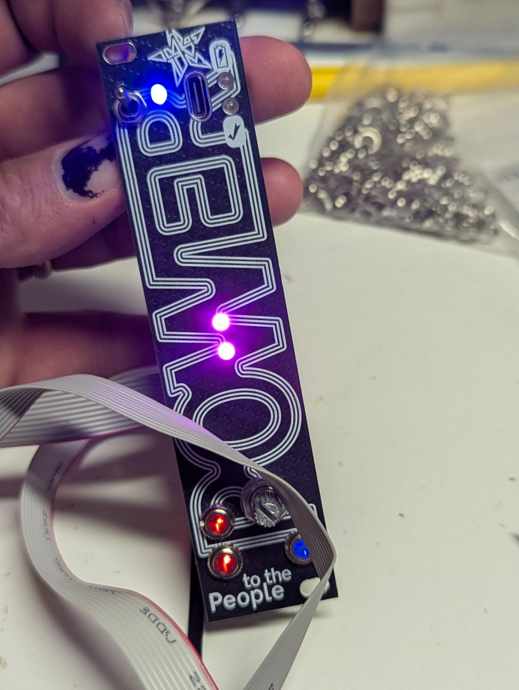
Here's a Eurorack module that powers other Eurorack modules. You can take a very modest skiff of modules with you on the train! Wait no you can't because how can you listen to it WAIT YES YOU CAN because this module also has a headphone amplifier. Buy a kit from hivemindsynthesis or track me down and make me sell you one, and let's BUILD THIS TOGETHER!
Supplies
BOM:
- SMT-assembled PCB and faceplate
- 3 x SMD LEDs, 1206, 2 x red, 1 x blue
- 2 x IDC boxed power headers, 2x8
- 1 x battery header, 2-pin JST XH 2.54mm plug
- 1 x micro toggle switch on-on, SMTS-102
- 1 x dual-gang vertical box-style sealed pot, 100K, RV0972G
- 5 x 3mm round LEDs: 1 x blue, 1 x red, 1 x green, 2 x orange or red or something dimmer than PINK
- USB-C vertical through-hole 6 pin 10.5mm tall..... there are WAY too many of these out there to reliably pick the right one. Just get one from me.
- The switch, potentiometer and jacks will have nuts and washers as well
- 2 x Eurorack ribbon cables with a 16-pin cable header on at least one end
- Some kind of lithium ion cell. This module will work with anything that can provide enough current, I've tested it with "dead" laptop cells, suspicious 18650 cells, they've all worked just fine
- Some way to affix the lithium cell onto the module. Use a cylindrical cell and zip-tie it in place over the cable ends. Use something else and you'd BETTER secure it somehow because you do NOT want a lithium ion cell rattling around inside anything at all, let alone a box of expensive electronics with sharp pointy metal bits.
- Solder, iron, flush-cut snippers, flux, pliers, all the stuff you KNOW you need because duh
SMD LEDs! for Under the Jacks
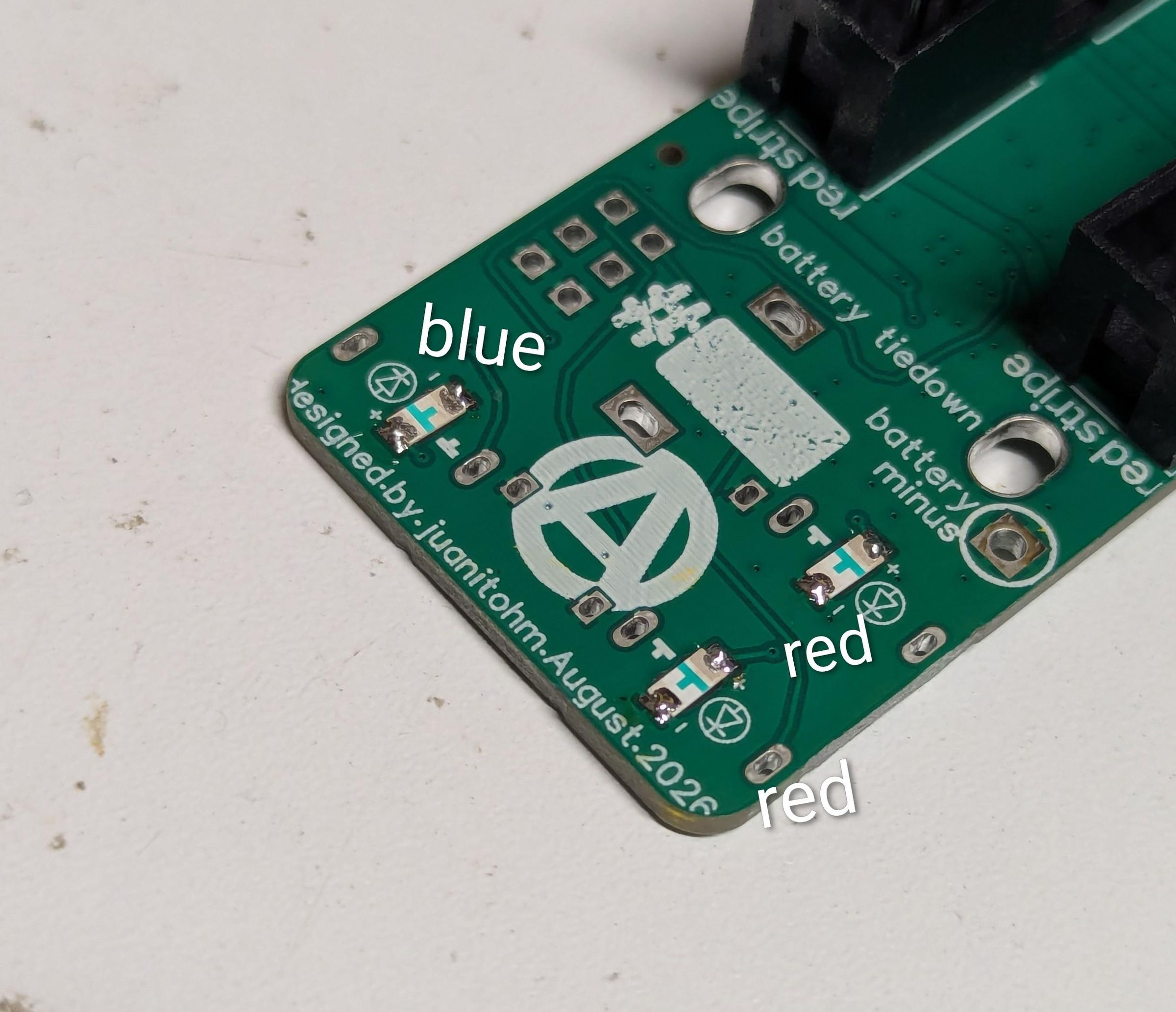
Place the SMD LEDs into the little square holes. Pay attention to the polarity of the LED, make it match the polarity markings close to each hole. M4TM jack standard colors are: RED - primary inputs; GREEN - an input that alters something, so CV inputs generally; BLUE - primary outputs; PINK (or whatever) - something else.
You're free to omit these little LEDs if you want to maximize the current output and battery life of your module.
Do you need a 5V rail???
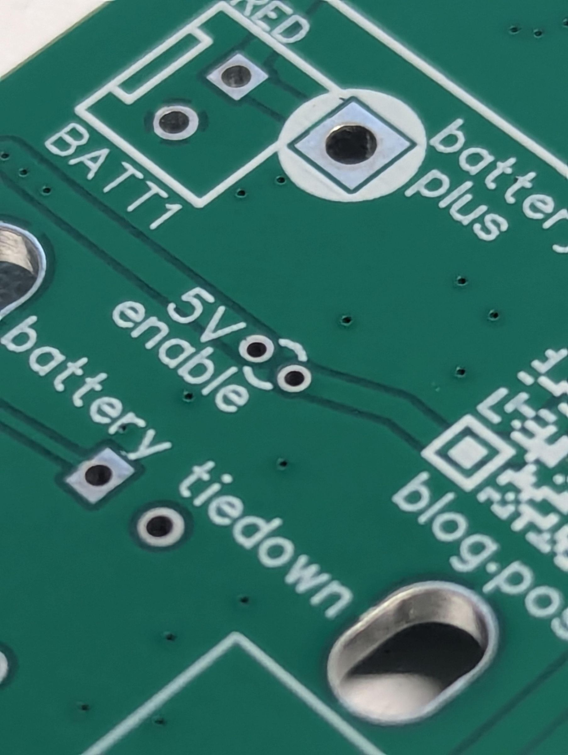
Choose now. If you want to have a 5V rail, use a bit of wire to jump the spot on the PCB labeled "5V enable". There's a linear voltage regulator onboard that will turn the boosted 12V into 5V, and it will draw a very small bit of current if you end up enabling it but not needing it.
POWER Output Headers
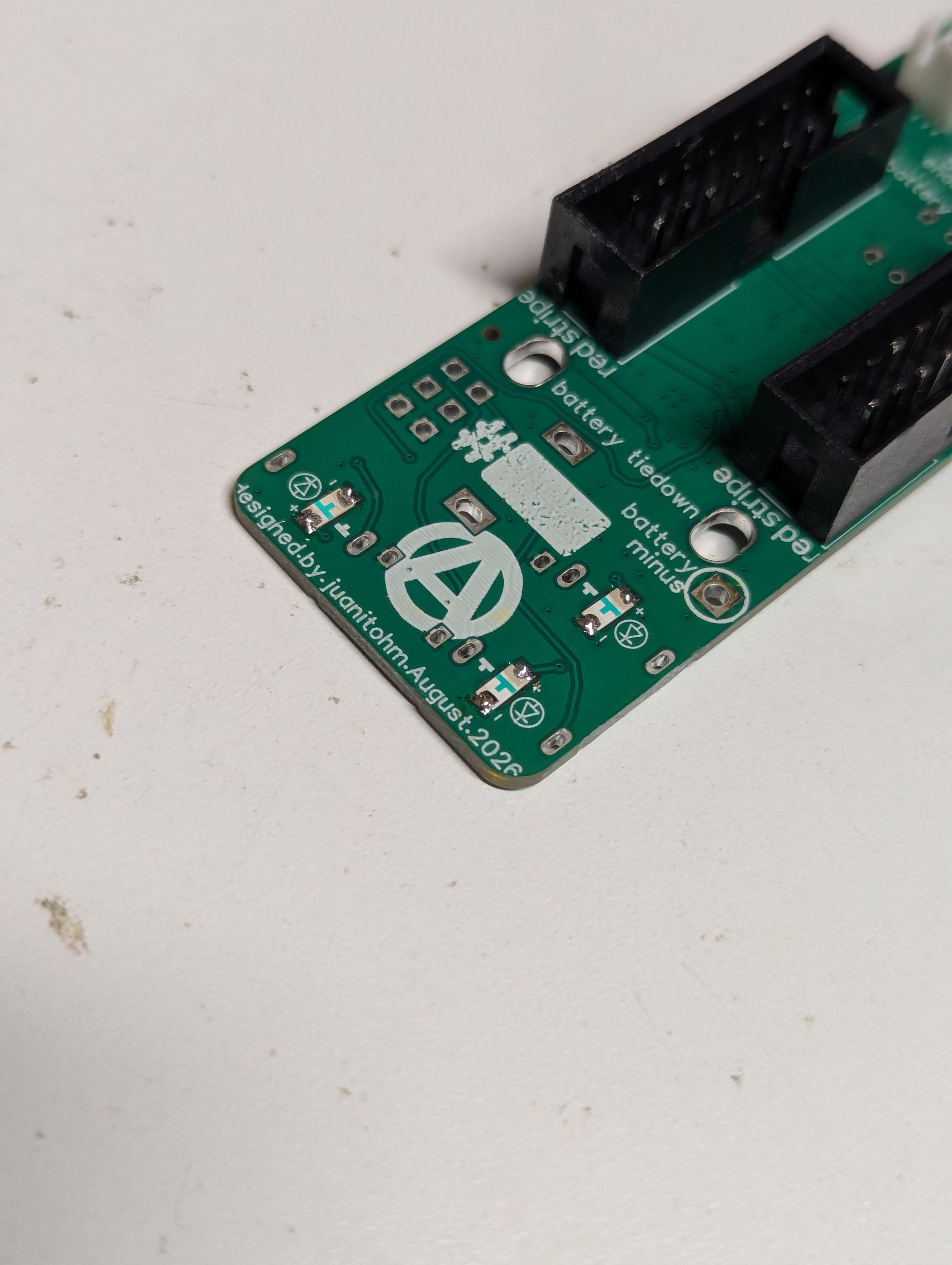
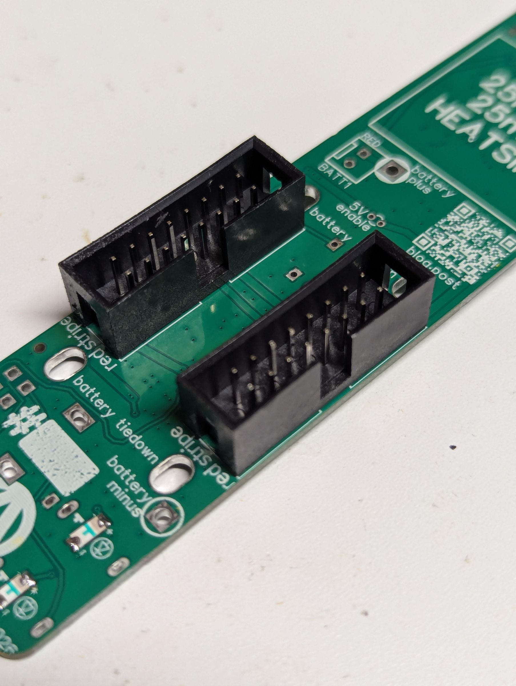
Put two IDC boxed headers where they go. LOOK AT THE MARKS ON THE PCB, and match the slot in the side of the box to where it goes on the PCB. This is super important. Put the header on the wrong way around, and nothing will work, and modules might fry.
Battery Header!
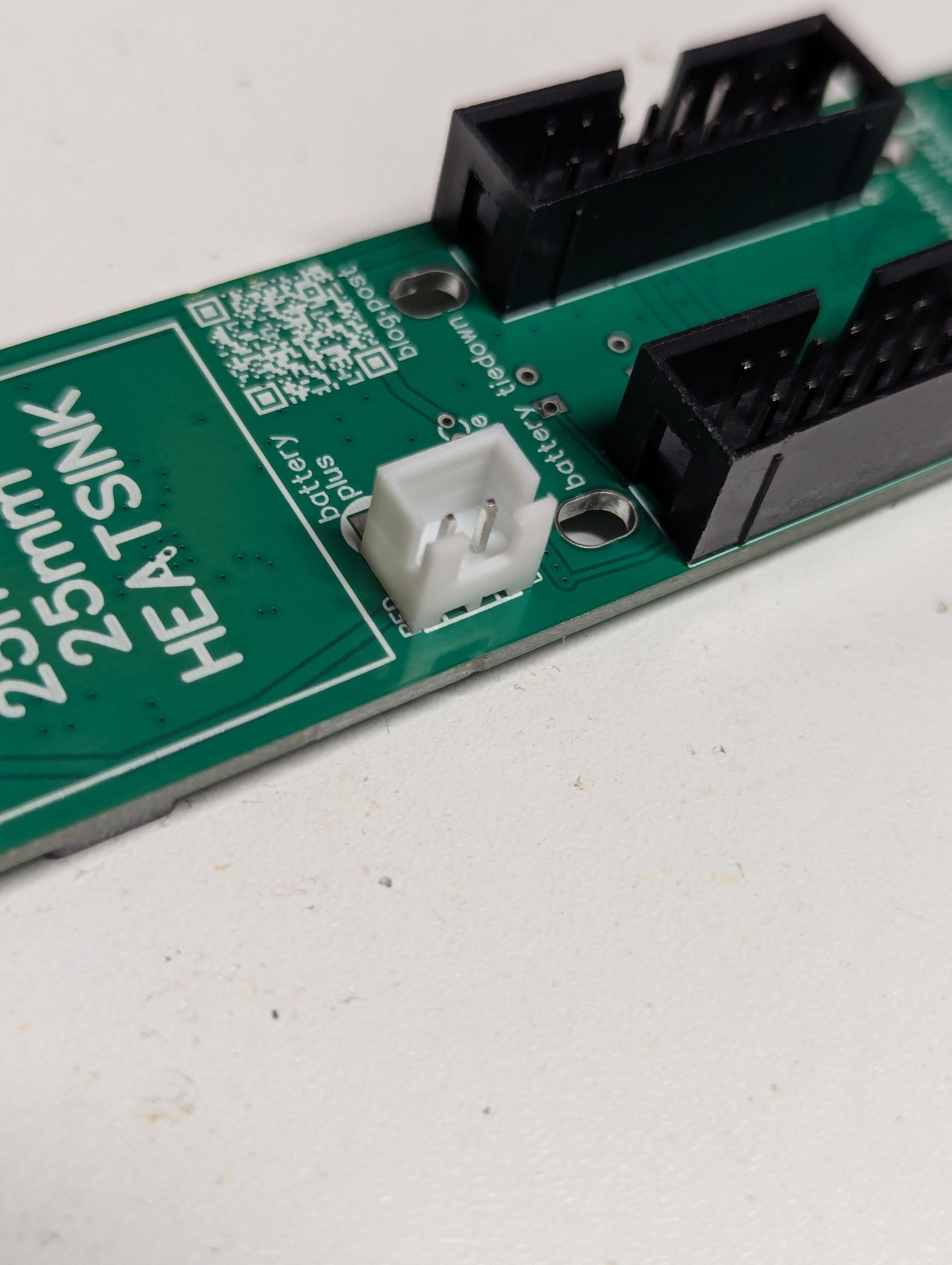
If you're building this module with me, I will provide a 18650 cell all safely wrapped up with a little pigtail already attached.
I STRONGLY RECOMMEND USING A BATTERY HEADER LIKE THIS
WHY?????
Lithium batteries are dangerous!!! They're filled with flammable substances and electrons. They want to be on fire. Most lithium ion chemistries have an oxidizer built in. It's like they were designed to be rocket fuel. If you short them out, they will absolutely destroy themselves, possibly damaging attached electronics, and might explode and cause a fire.
Having said that, this circuit has overcharge protection, undercharge protection, short circuit protection, so it's as safe I could design it.
Absolutely put the battery header in the right way. Red goes by red, and the PCB marking should match the notch in the header.
"Can I use more than one cell in parallel with this module?" is a question I just wrote here. Sure. Lithium-ion batteries are happy to run in parallel, but the more complicated your battery setup, the more failure modes exist. Be so careful.
Switching It Up
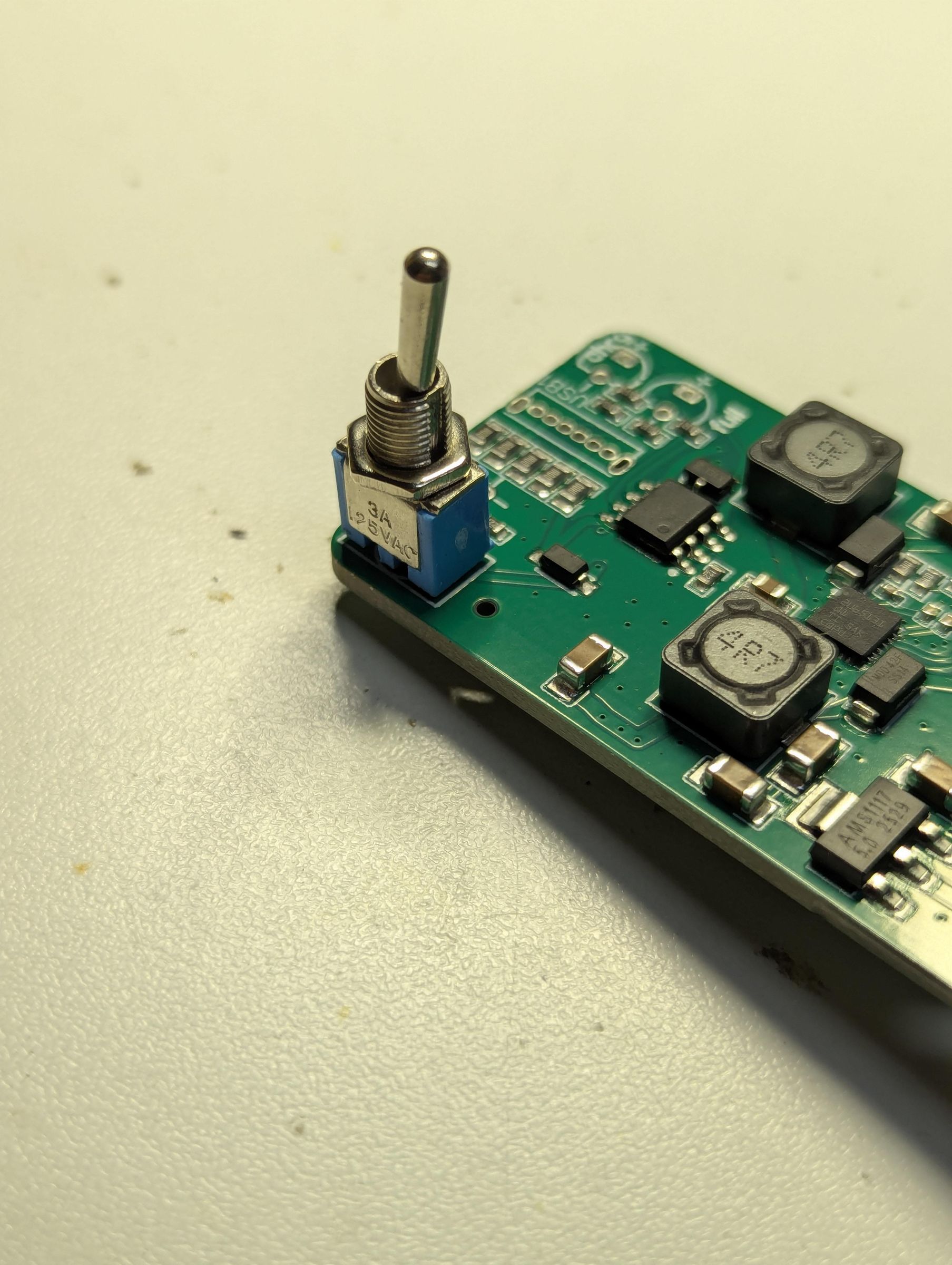
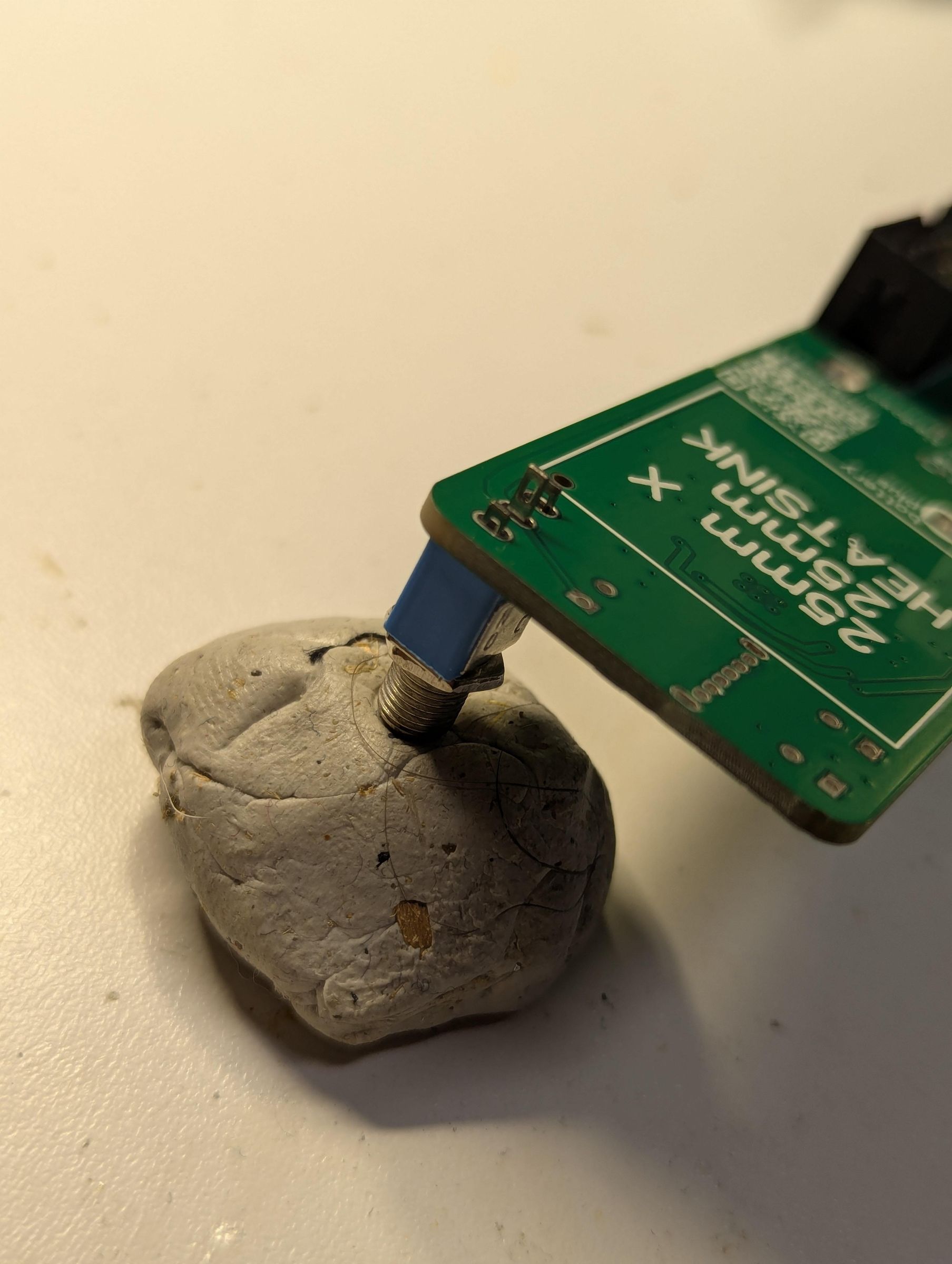
Slap that toggle switch in! I used a (pretty gross, apparently) chunk of poster putty to hold the switch in place while soldering. It's important that the switch is nicely vertical. It's the only thing holding the top of the PCB to the faceplate.
Mono Jacks
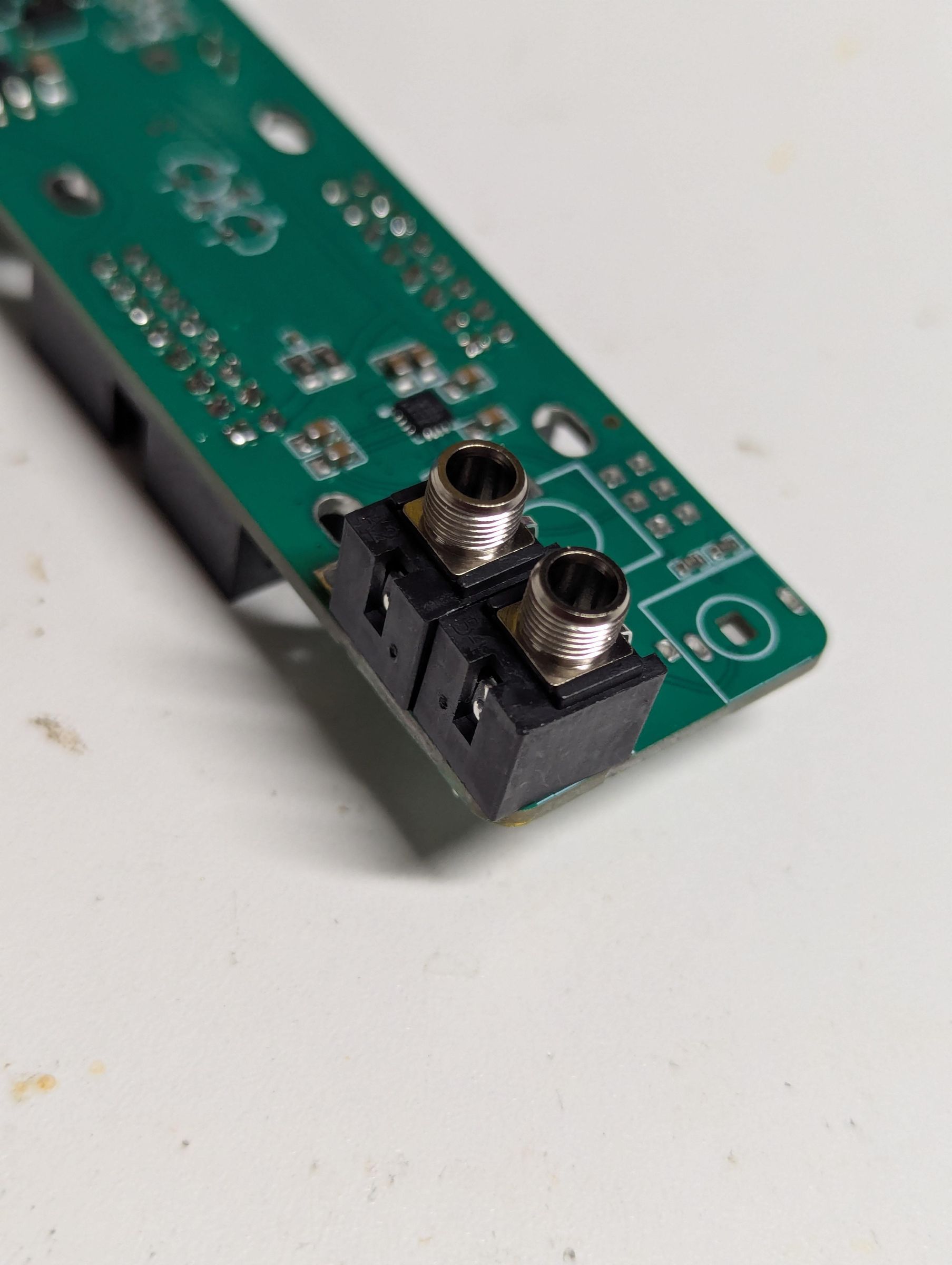
Toss the two mono jacks where they go. Right next to each other. Make sure they're tight to the PCB and solder them in place!
The top mono jack is normalled to the 2nd jack, so plug a mono signal into the top jack to get that signal from both of the stereo outputs. Plug something else in the lower mono jack (the other half of the stereo audio, one would hope) and you'll get that signal at the other output.
Stereo Jack
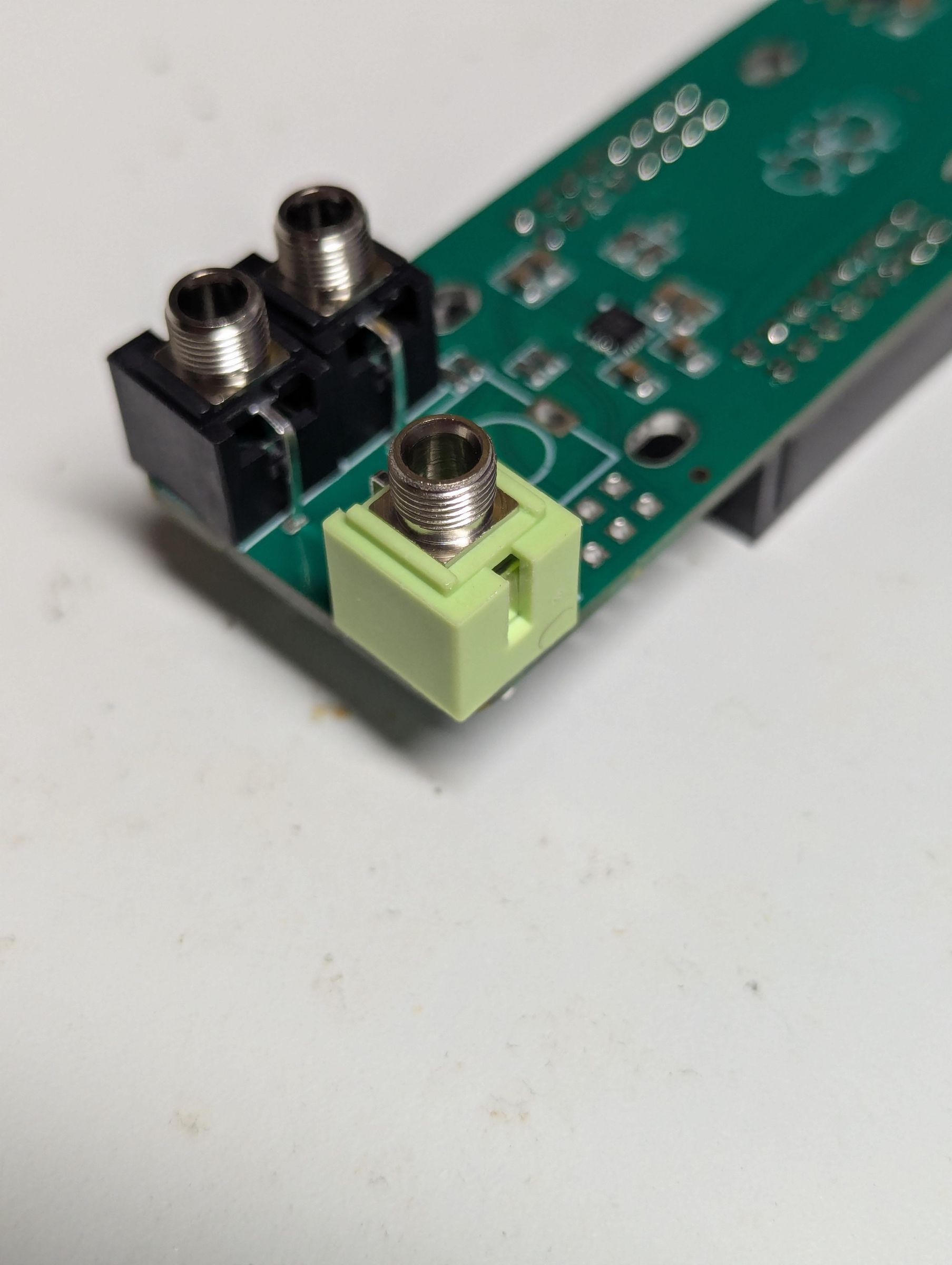
The stereo jack is green. It goes there.
Dual Gang Potentiometer
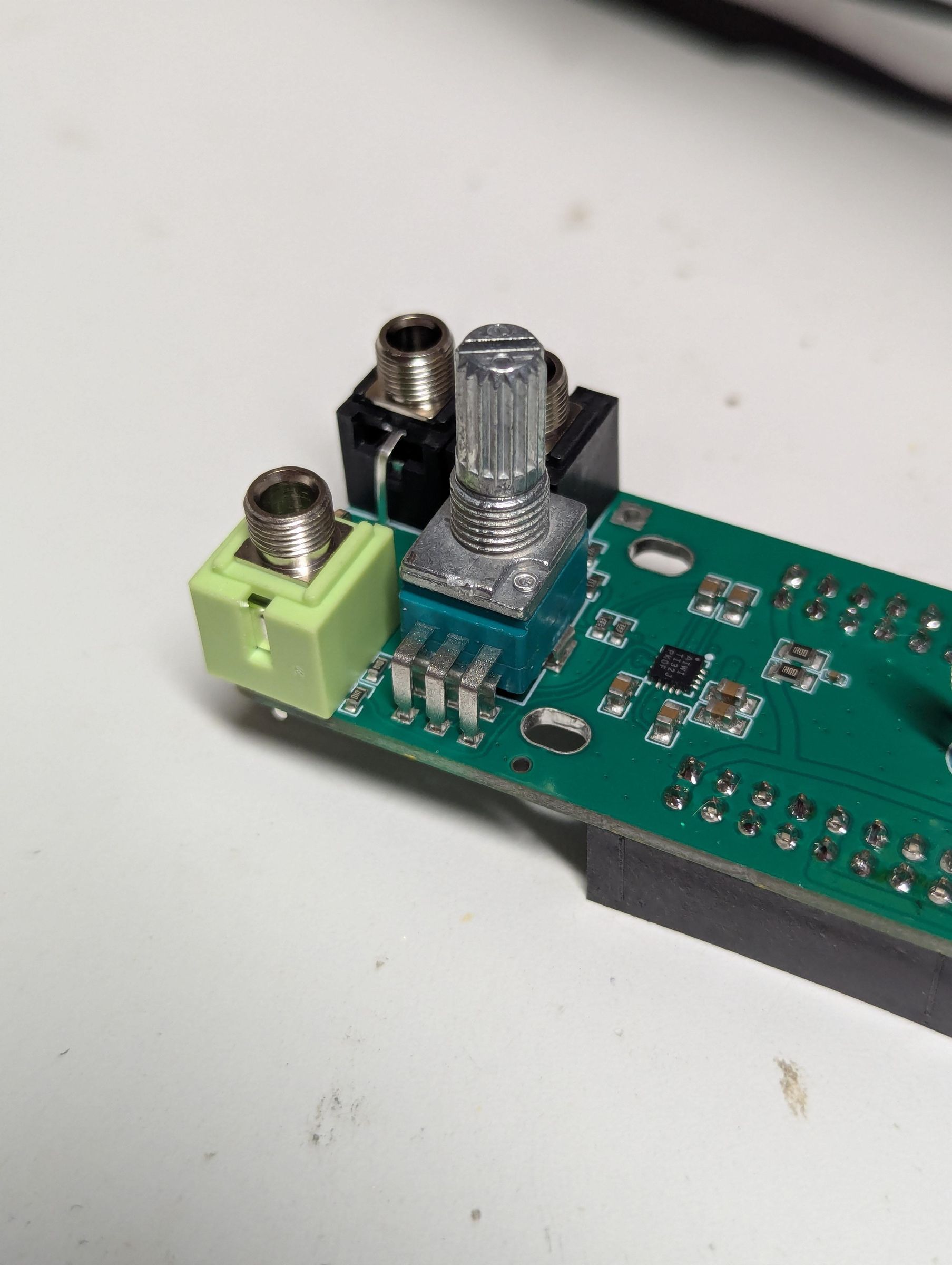
The dual gang pot goes there. Check to see if there's a locator tab on the face of the jack. If it's there, remove it. You can use pliers, a file, snips, a Dremel, and probably like five other ways I'm not thinking of.
3mm LEDs
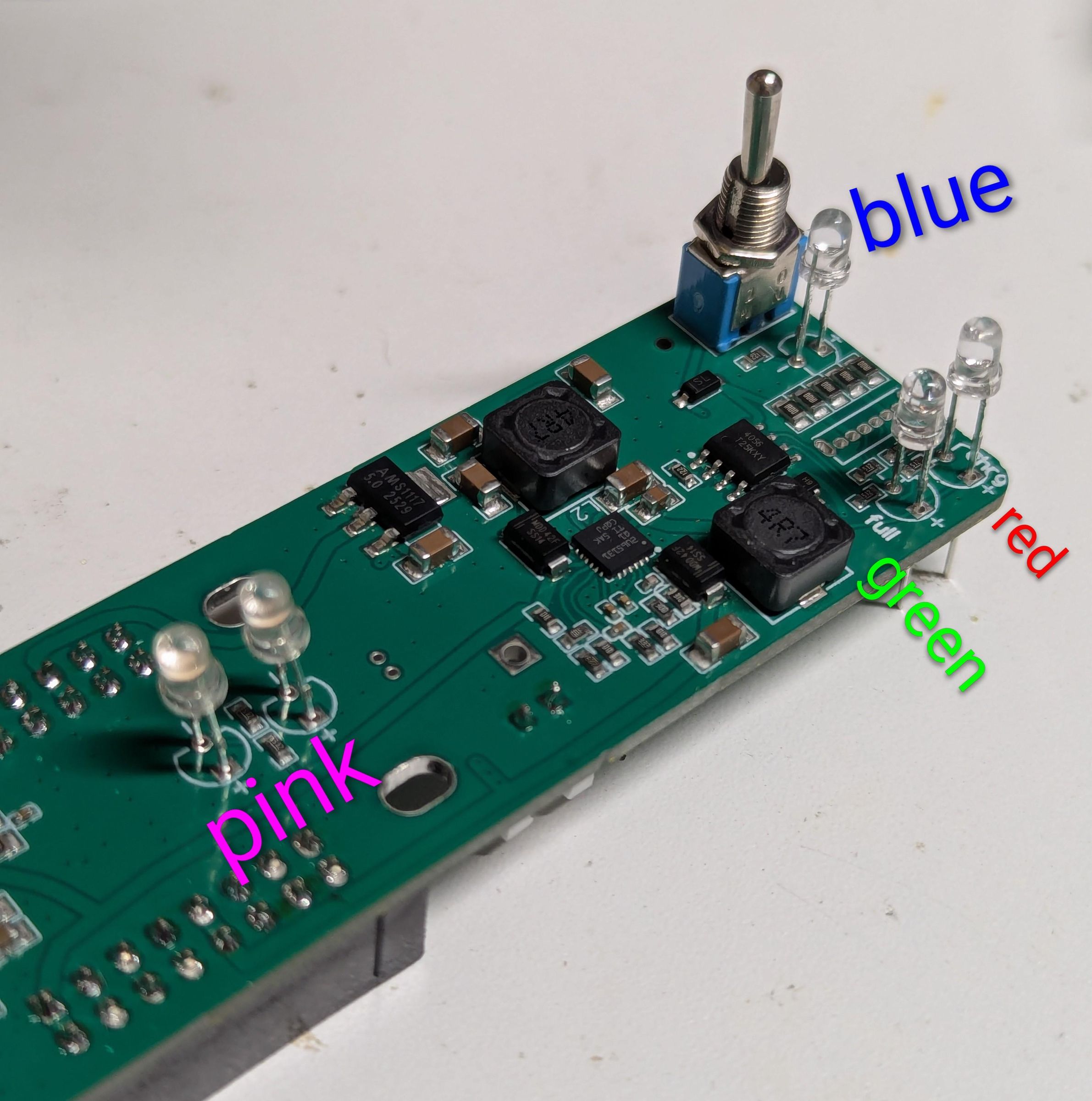
Don't solder these in place yet!
The blue LED is to show the module is powered on.
The red LED means the battery is charging.
The green LED goes in the "fully charged!" spot
The two ORANGE LEDs (pink was way too bright) show the status of the +12V and -12V rails
Absolutely pay attention to the polarity of the LEDs. The longer leg goes in the square hole.
USB-C Jack (the Most Fiddly Step)
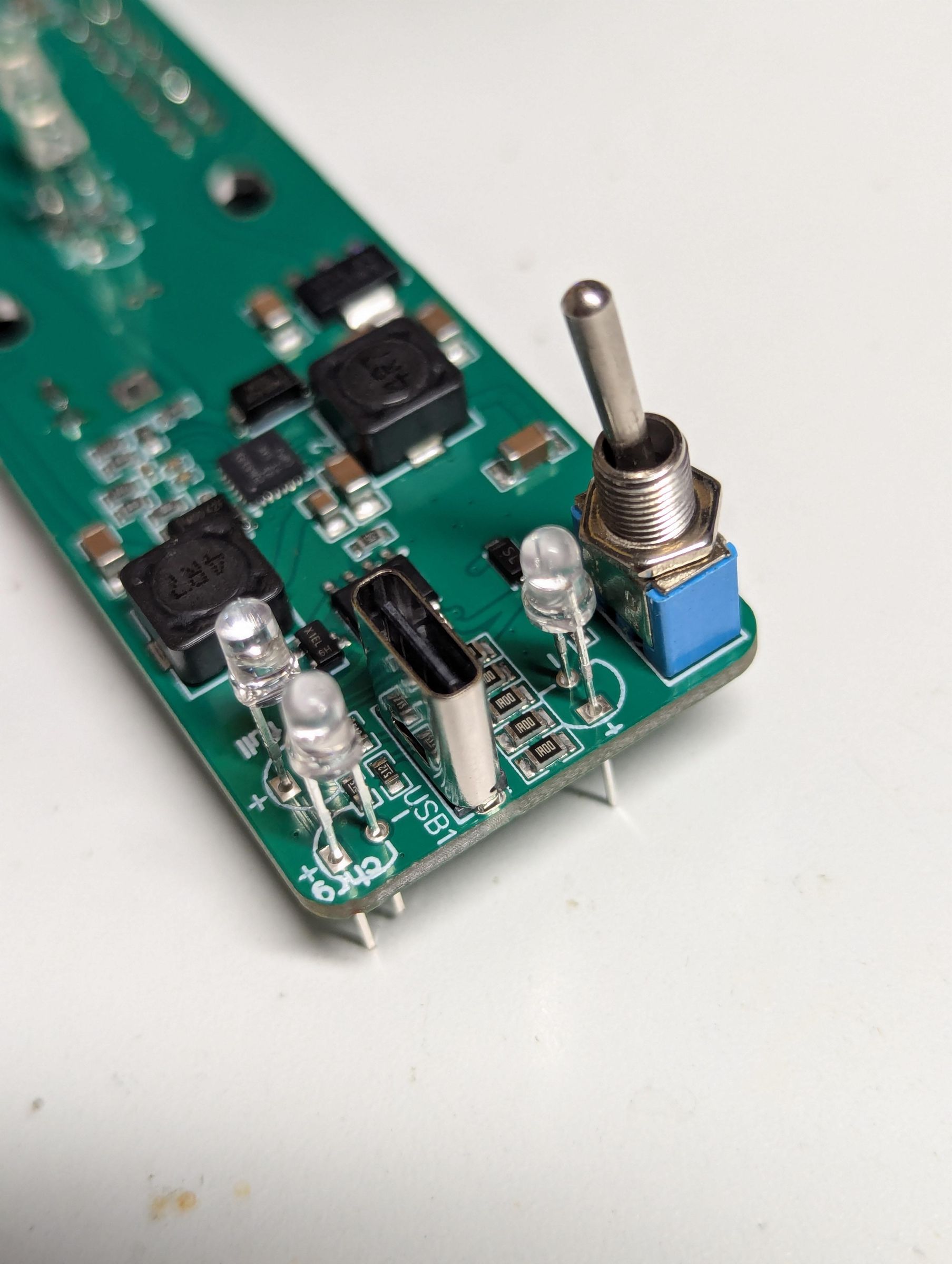
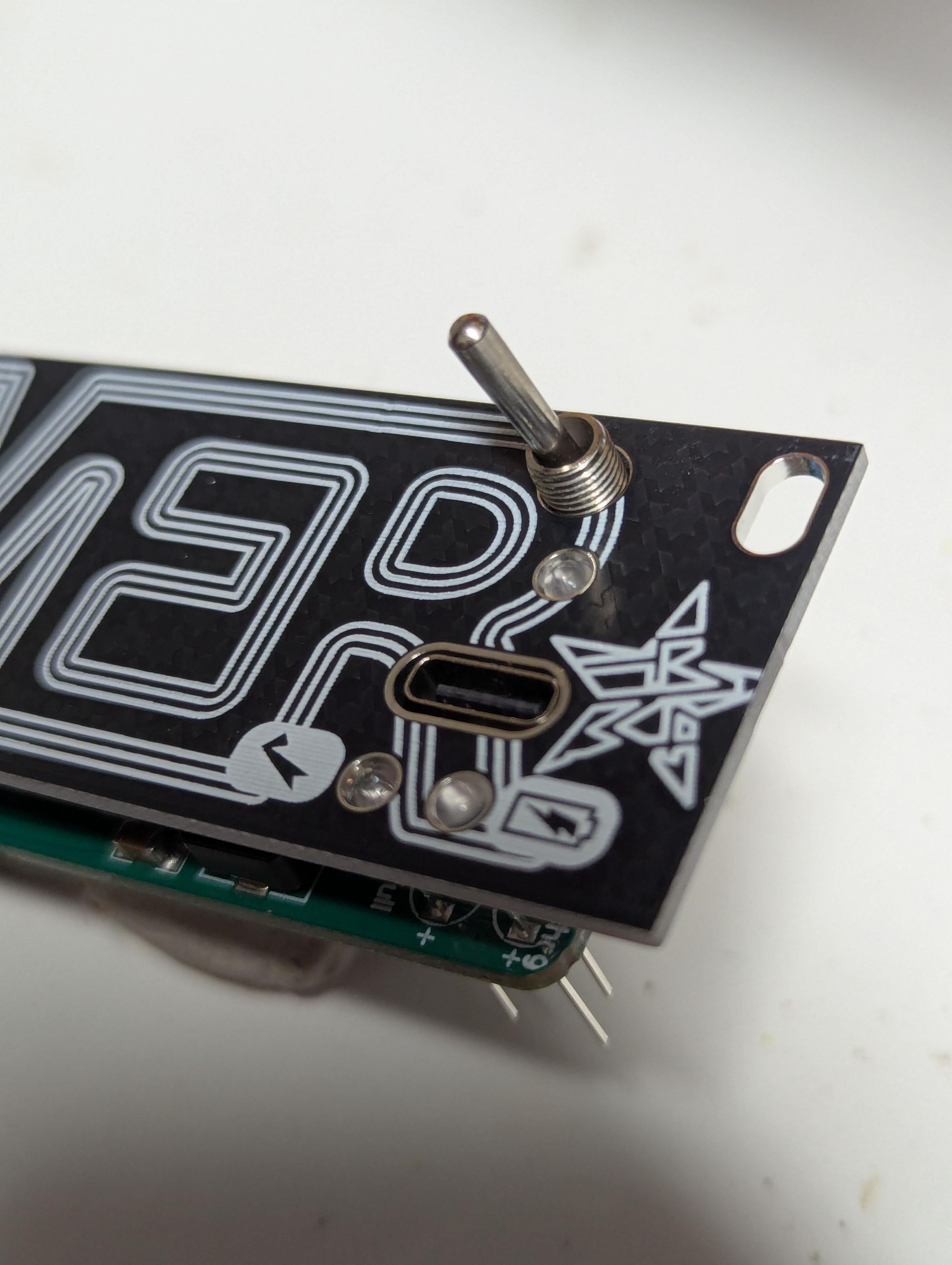
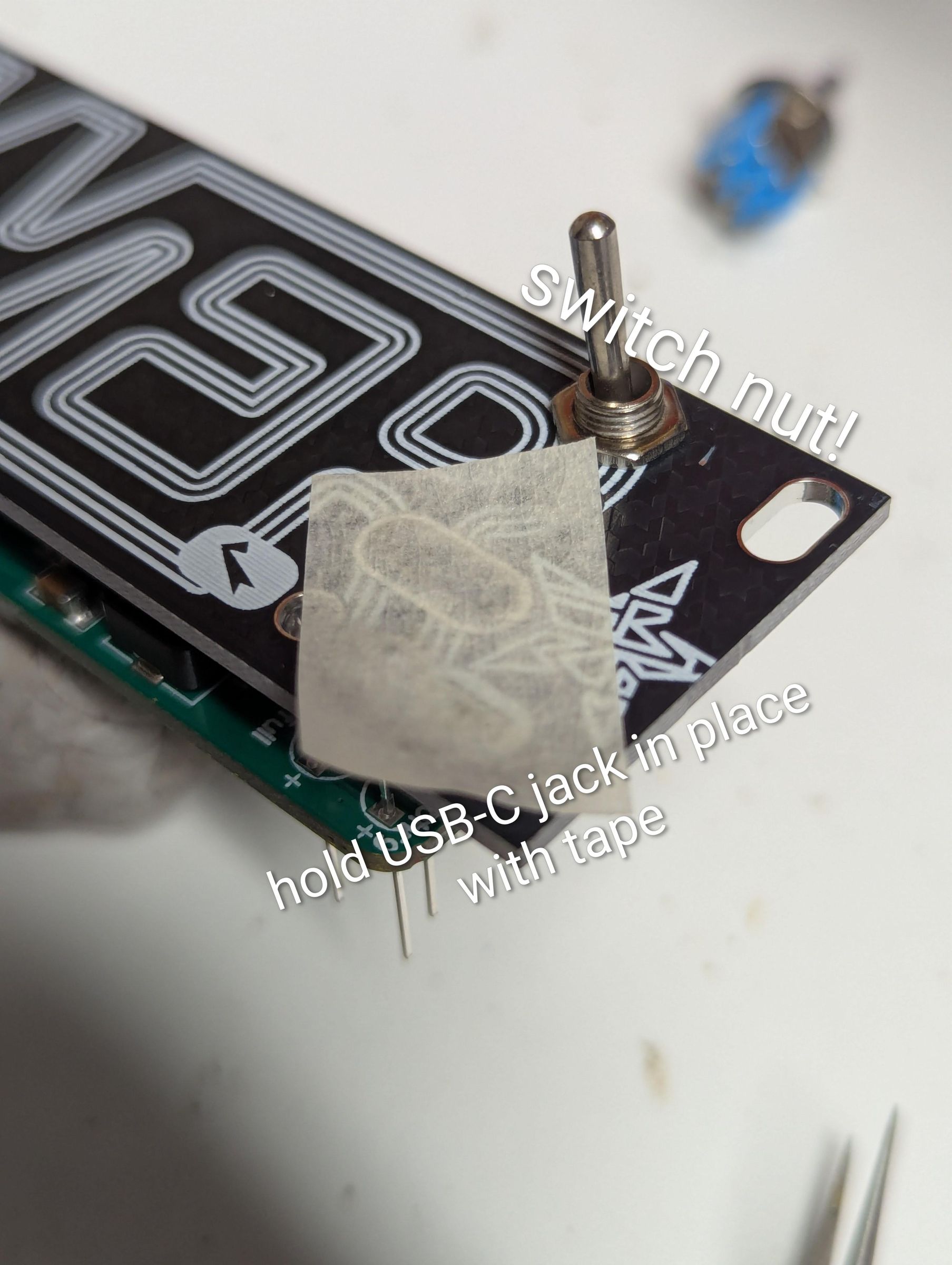
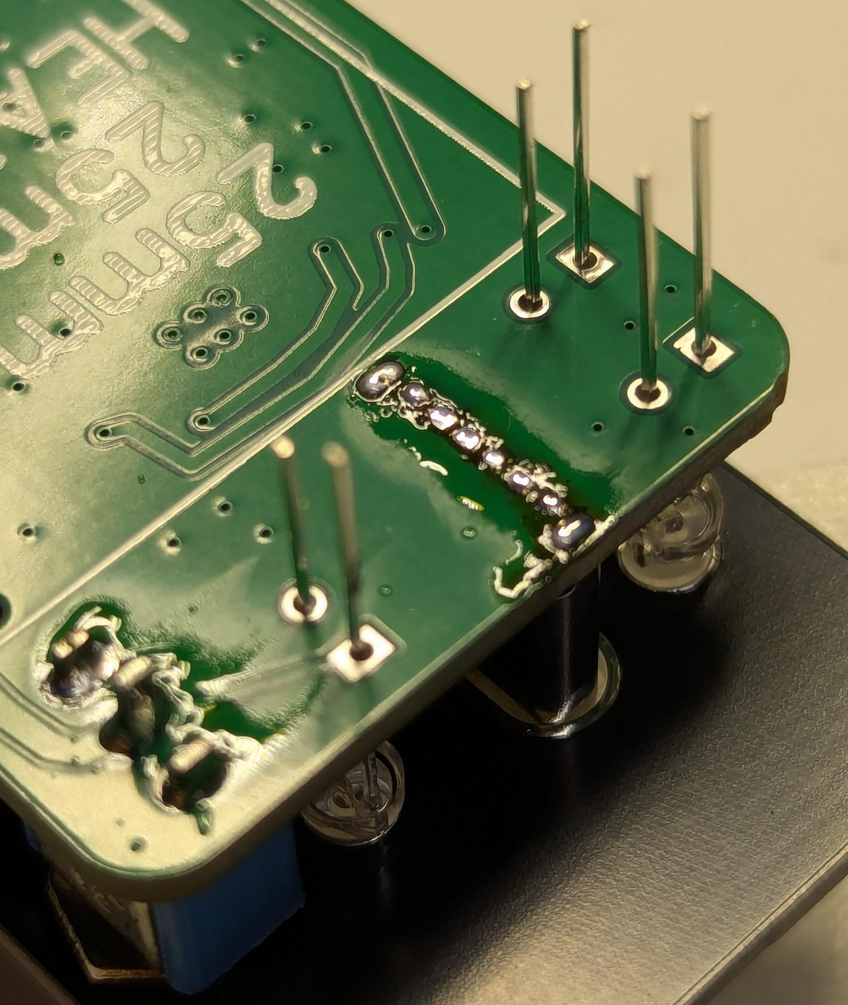
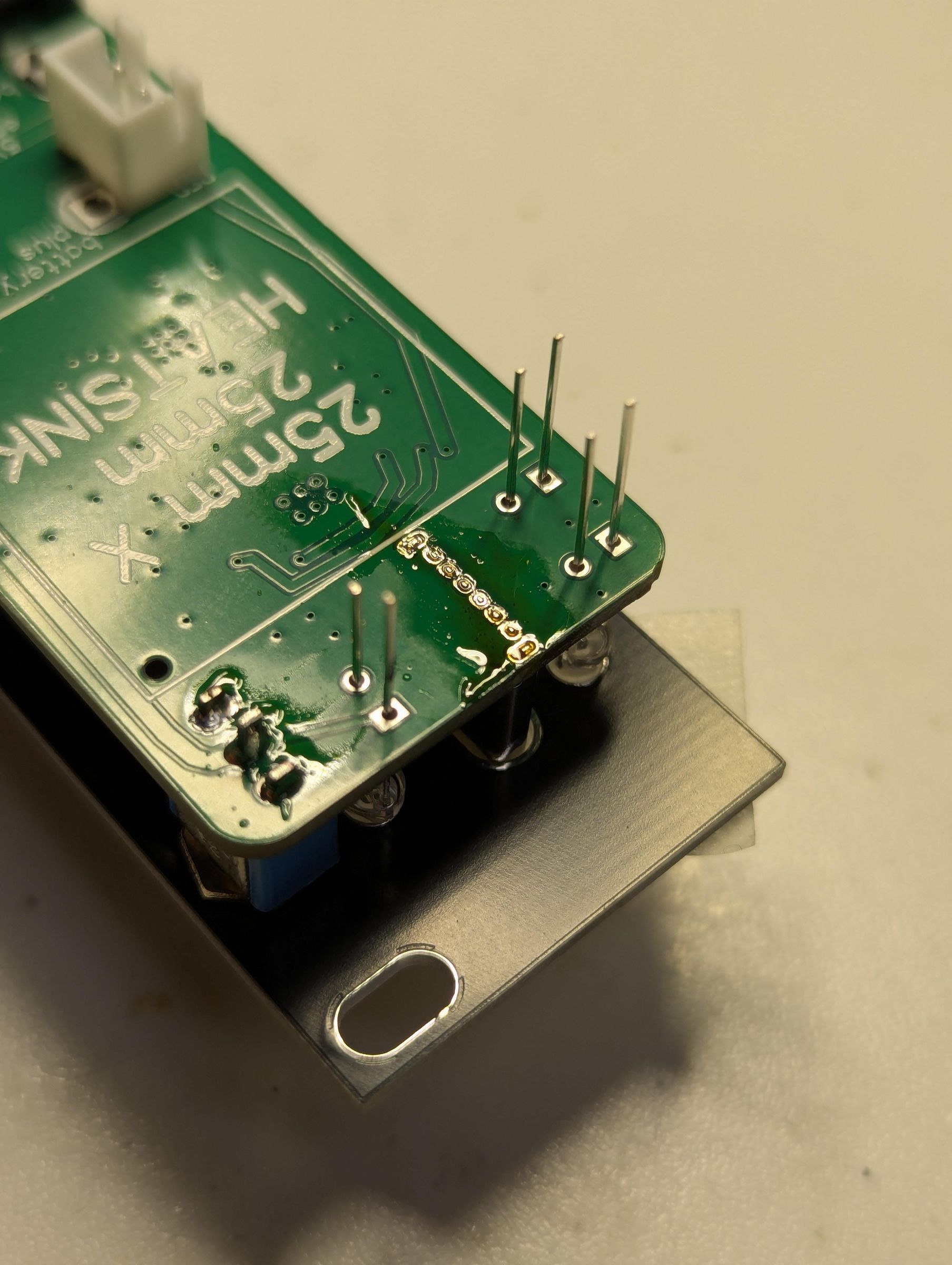
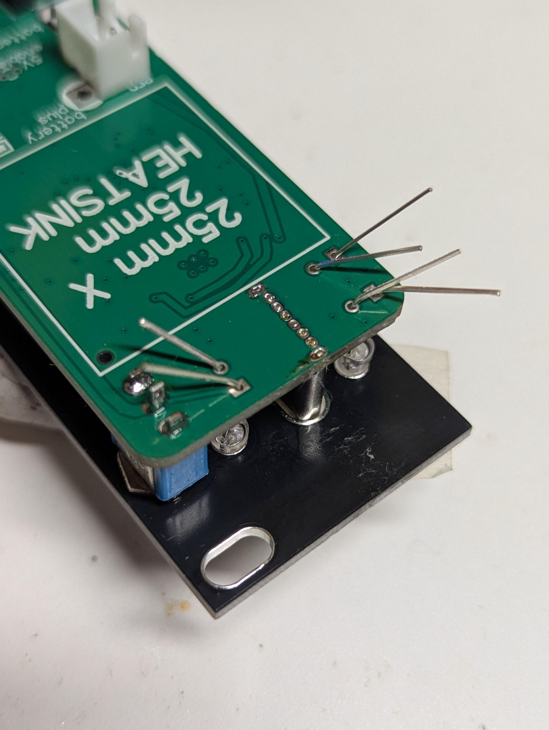
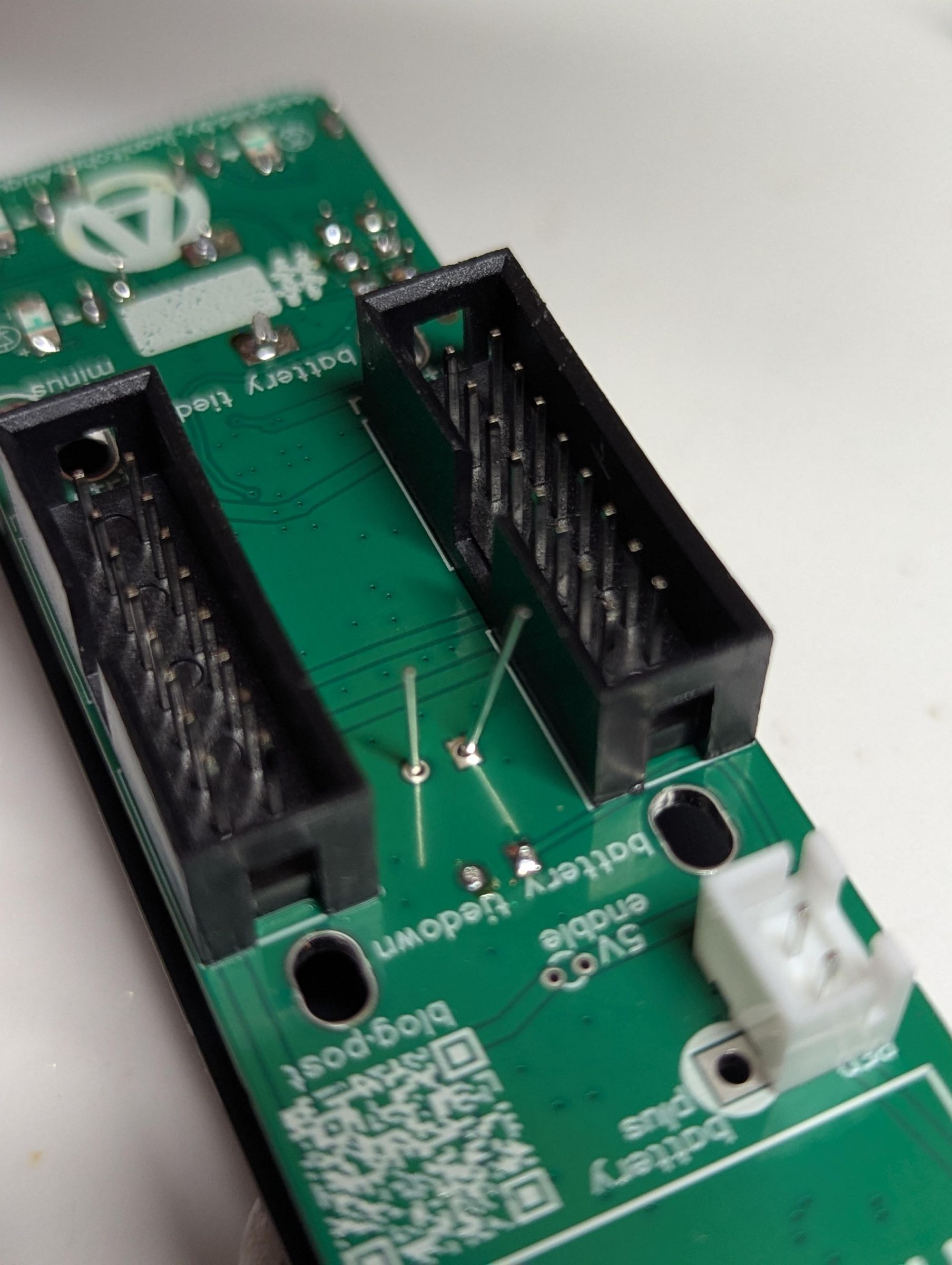
The USB-C jack needs to go in right. The pins are little, fiddly, and doesn't stay securely in the PCB.
So... carefully place the jack in place. Then install the faceplate, attaching at least the switch nut to hold the panel securely in place. When you're happy with the placement of the USB jack, use tape to secure it so you can turn the project over without it falling out.
Solder all the pins. Use plenty of solder, use flux if you feel like it needs it.
If (since) there's too much solder, use some wire or desoldering braid with flux to remove excess solder.
Clean it up if you feel so inclined.
Now do the LEDs!
Move them so they're aligned with the holes, and stick out the correct amount (a matter of taste), and solder them in place, and clip the excess lead.
Heatsink
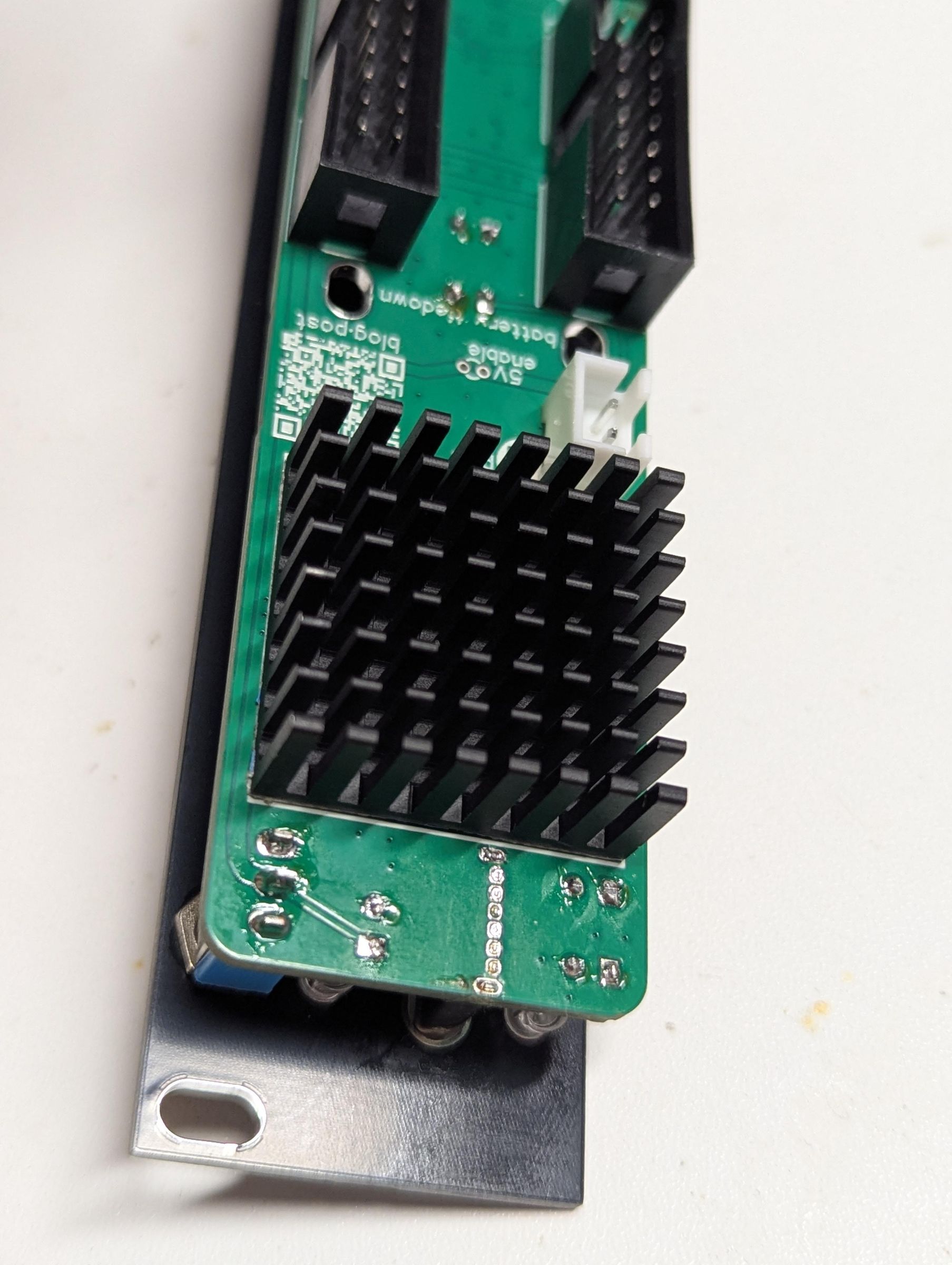
Peel the backing from the adhesive on the heatsink, and press it firmly in place. It'll get surprisingly hot.
Power Cables, Battery, Zip-ties
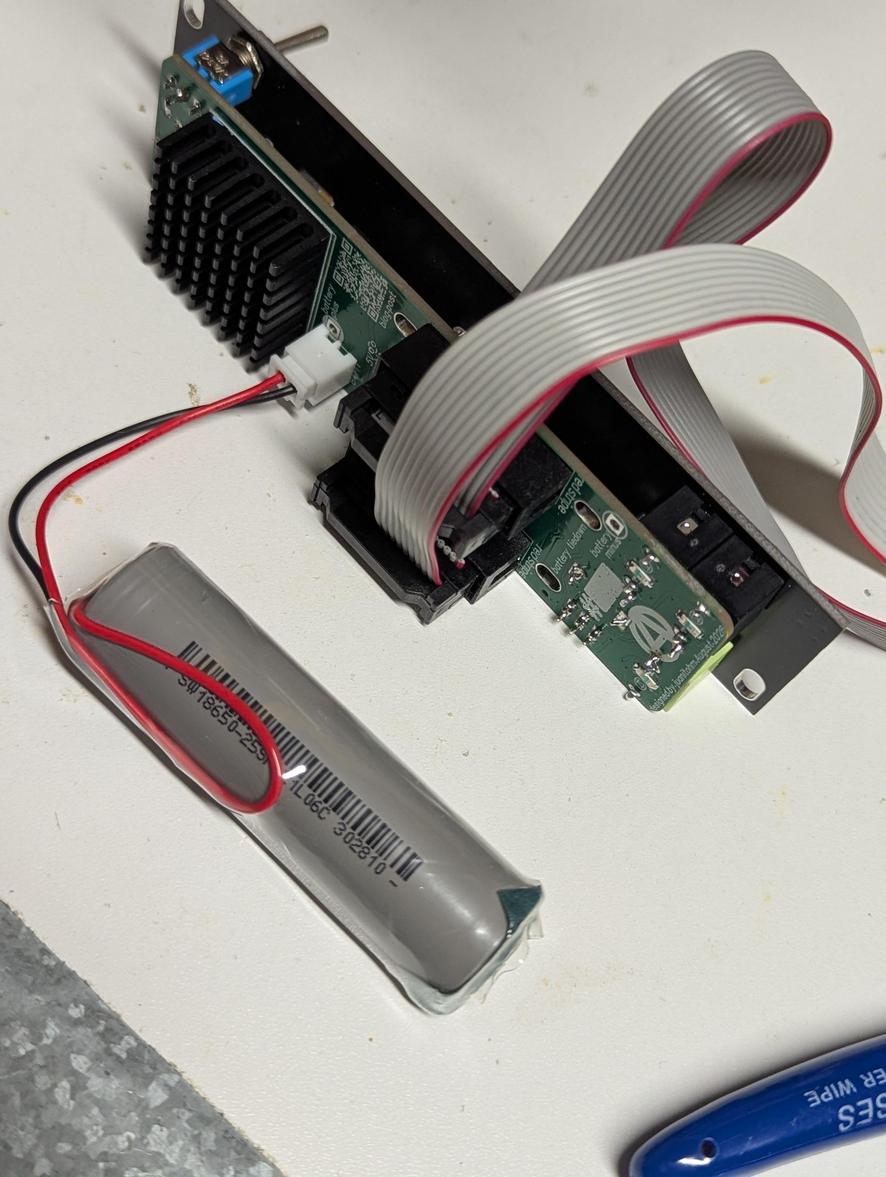
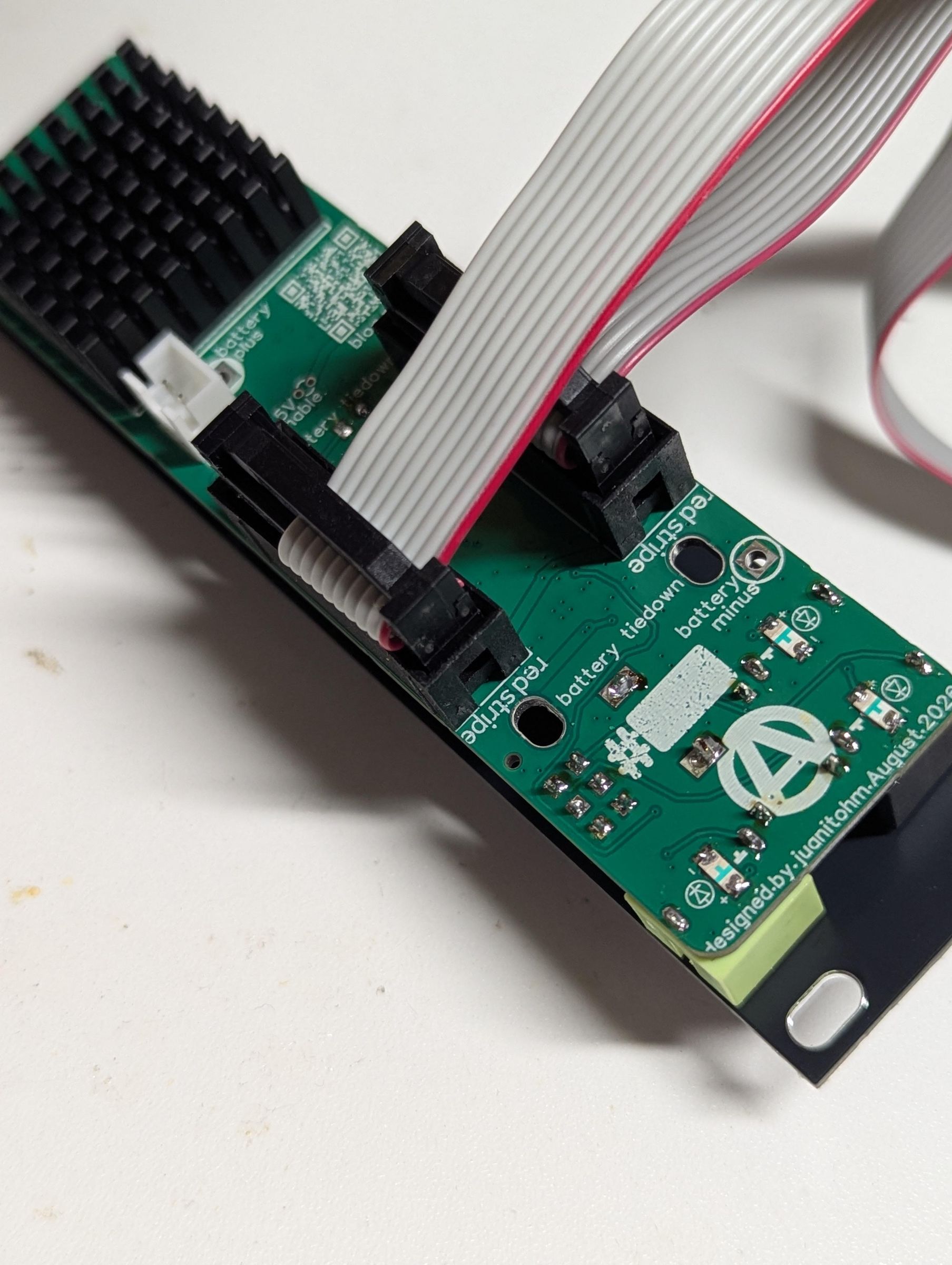
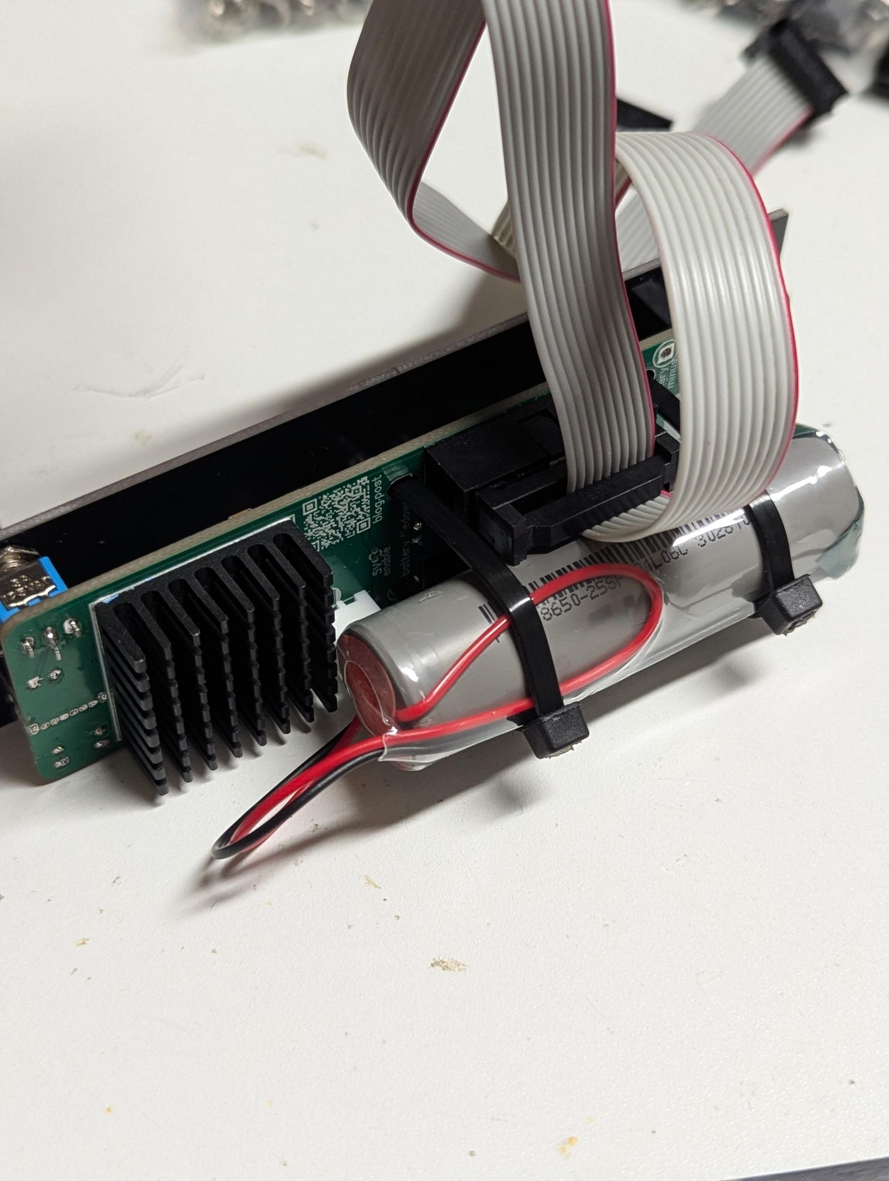
First, install the Eurorack cables. Next, plug the battery in, perch it on the Eurorack cable ends, slip zip-ties through the tiedown holes, and gently tighten them against the cable ends. The boxed headers are strong, and the cable ends are nigh-indestructible, but there's no need to Hulk Mode tighten those ties and bend things around.
A note about Euro cables for using with more than 2 modules
You can have two (or more, yikes) "distal" ends on a ribbon cable like this, allowing more than one module to be plugged in with one cable. We've all seen cables like this. If you need to use more than two modules with this PSU, that should be fine, as long as they're not drawing more than about 200mA in total. The module will gracefully voltage-sag under heavy load, but you're unlikely to damage it this way.
Juanito has more 10-pin Euro cable ends that we could attach to your cables if you want.
Finishing Up!
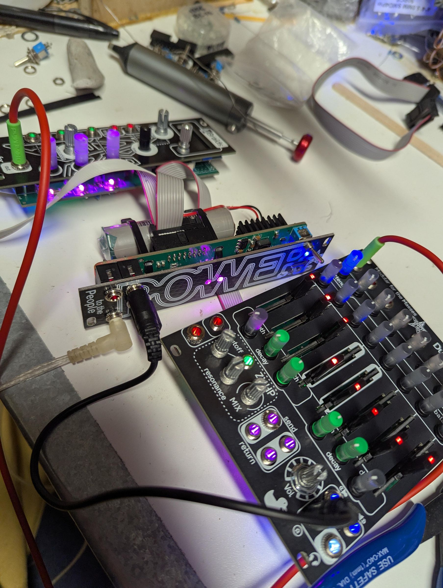

It's time to switch your module on! Look for the power light to come on, and the two rail LEDs.
It's working! You rule!!!
In these pictures, I've plugged in my current-hungry 8-channel mixer with LOTS of LEDs, and a Braids clone. I'm listening to the onboard headphone amp with IEMs, trying to hear PSU noise or degradation, aware that the power supply is being pushed pretty hard. It sounds great!
Some USB-C power supplies won't charge this module. It's only capable of charging at one amp, so there's no advantage to using a more powerful USB supply, and the fancier, smarter USB power supplies are less likely to be happy charging the battery. A fun thing about this module is that some DEAD-DEAD less-than-2V cells came back to life using this to charge them. I only encountered one cell that would not come back to life using this circuit.