PP9 Battery Replica

A vintage radio that I was renovating made use of a PP9 9V battery, including one of these would complete a sympathetic renovation.
However, these are hard to come by and if found rather expensive.
As an alternative I could use 6 x AA (1.5V), batteries in series using a suitable holder. A double sided (2 x 3), battery holder would fit in the space although it would need some sort of retainer (foam or partition), to prevent excessive movement which may cause damage to the components.
However, I would need some suitable snap connectors (larger than those required for a PP3 9V battery), these too proved difficult to obtain. Luckily, I had some in my spares box.
I had the means to provide the correct voltage with suitable connectors but the result was not in keeping with the vintage radio. Hence the requirement for a battery replacement.
This instructable details the process in creating a PP9 replacement.
Supplies


6 (2*3) AA or equivalent, batttery holder (this option also comes with PP3 snap connectors)
PP3 or equivalent (9V) battery snap stub connector.(in the event that the battery holder is without PP3 snap connectors).
PP9 or equivalent battery snap connectors.(Ebay or an old battery are optional sources.)
M2 x 8mm countersunk screws - Qty 6
M2 knurled threaded standoff - Qty 4
M2 nuts - Qty 2
AA or equivalent batteries - Qty 6
May prove more cost effective to buy a range of values rather than individual values unless you already have them available. Some components may also have a MOL greater than the quantity specified in the component list.
3D Printer
Black Filament
1.5mm drill bit
2mm drill bit
3mm drill bit
Drill
Pliers
Wire cutters
Soldering Iron
Solder
Sanding paper
Screwdrivers
Pencil/Marker
Awl
Ruler
Colour document printer
Paper for a suitable printer
Paper Hole Punch
Tape
Flexible adhesive that sticks paper and plastic.
Know your tools and follow the recommended operational procedures and be sure to wear the appropriate PPE.
No affiliation to any of the suppliers used in this project, feel free to use your preferred suppliers and substitute the elements were appropriate to your own preference or subject to supply.
Links valid at the time of publication.
Datasheet
First I needed a datasheet to identify the battery external measurements.
I found the datasheet for an Eveready Silver PP9* and determined that the minimum dimensions would produce a suitable fit. Body dimensions 63(W) x 50(D) x 77.9(H) mm, width between contact centres 34.6 mm
*Alternatives: Energiser 276, NEDA 1603,Varta 439, RayoVac RR9 etc.
Downloads
CAD Design
Taking the measurements I used BlocksCAD to create a replica body.
Contained within the centre of the replica body would sit the battery holder for 6 (2 x 3), AA batteries.
Sufficient clearance is required for the PP3 clip on the battery holder complete with wire and the back of the lid.
Provision to hold the PP9 snap connectors in place and maintain electrical connection to the PP3 connector.
The lid would be held in place with 4 x corner screws.
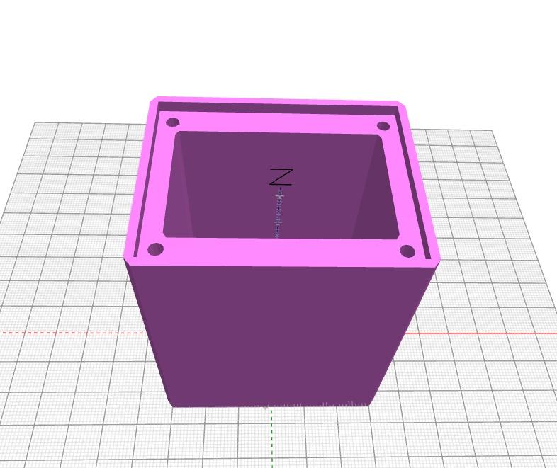
Three elements are created.
Body : Main element that houses the batteries.
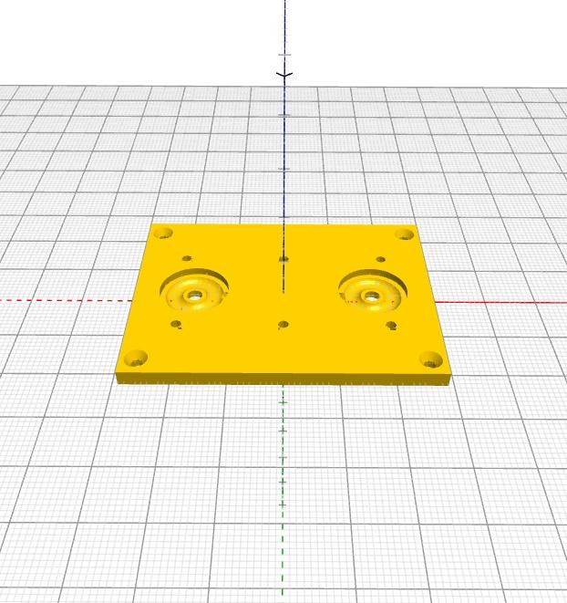
Lid : To which the PP9 snap connectors are attached and which also retains the contents of the body.
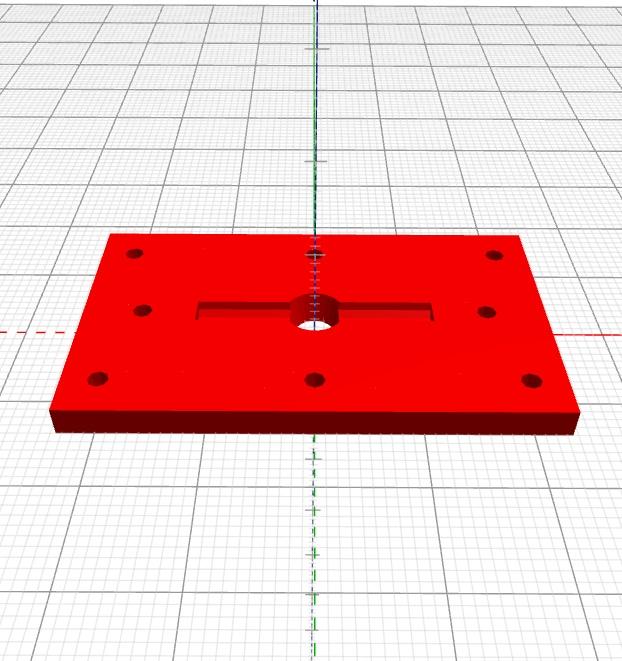
Back: This is attached to the back of the lid, isolating and protecting the two wires and helping to retain the PP9 snap connectors.
Printing


Filament: PLA (Black)
Layer Height: 0.15mm
Infill: 50% (Body), 100% (Lid and Lid back)
Infill Pattern: Cubic Subdivision
Wall Thickness: 0.84mm
Wall line count: 6
Bed Adhesion: Skirt
No supports
All parts are correctly orientated within the files for printing directly.
1: Body: 63(W) x 50(D) x 77.9(H) mm, Weight: 127g
2: Lid: 58(W) x 45(D) x 3(H) mm, Weight: 9g
3: Back: 47(W) x 28(D) x 3(H) mm, Weight: 5g
Post Processing
Some post processing may be required to remove aberrations in the cavities and around the edges with sanding paper and needle files in addition to opening and smoothing the holes with a drill bit.
Body Preparation


Due to printing variances it may be necessary to widen the 4 holes at the top of the body with a 3mm drill bit.
Once the holes are the required diameter press fit 4 x M2 X 10(L) mm threaded knurled standoffs into the holes using a pillar drill/vice or wide clamp.
Lid Prepartion


The lid is design to accept two individual snap studs with wires soldered to the back.
If wires are already soldered on the back of each stud remove these as you will be using the wires from the PP3 connector.
Press a nut in each hexagonal hole in the Lid Back, it may be necessary to use a soldering iron to seat these.
Pass the wires through the centre of the Lid back orientated with the horizontal slot facing uppermost.
With a 1.5mm drill bit clear out the two 45 degree holes either side of the stud holes in the lid.
Orientate the lid such that the circular depressions are facing uppermost.
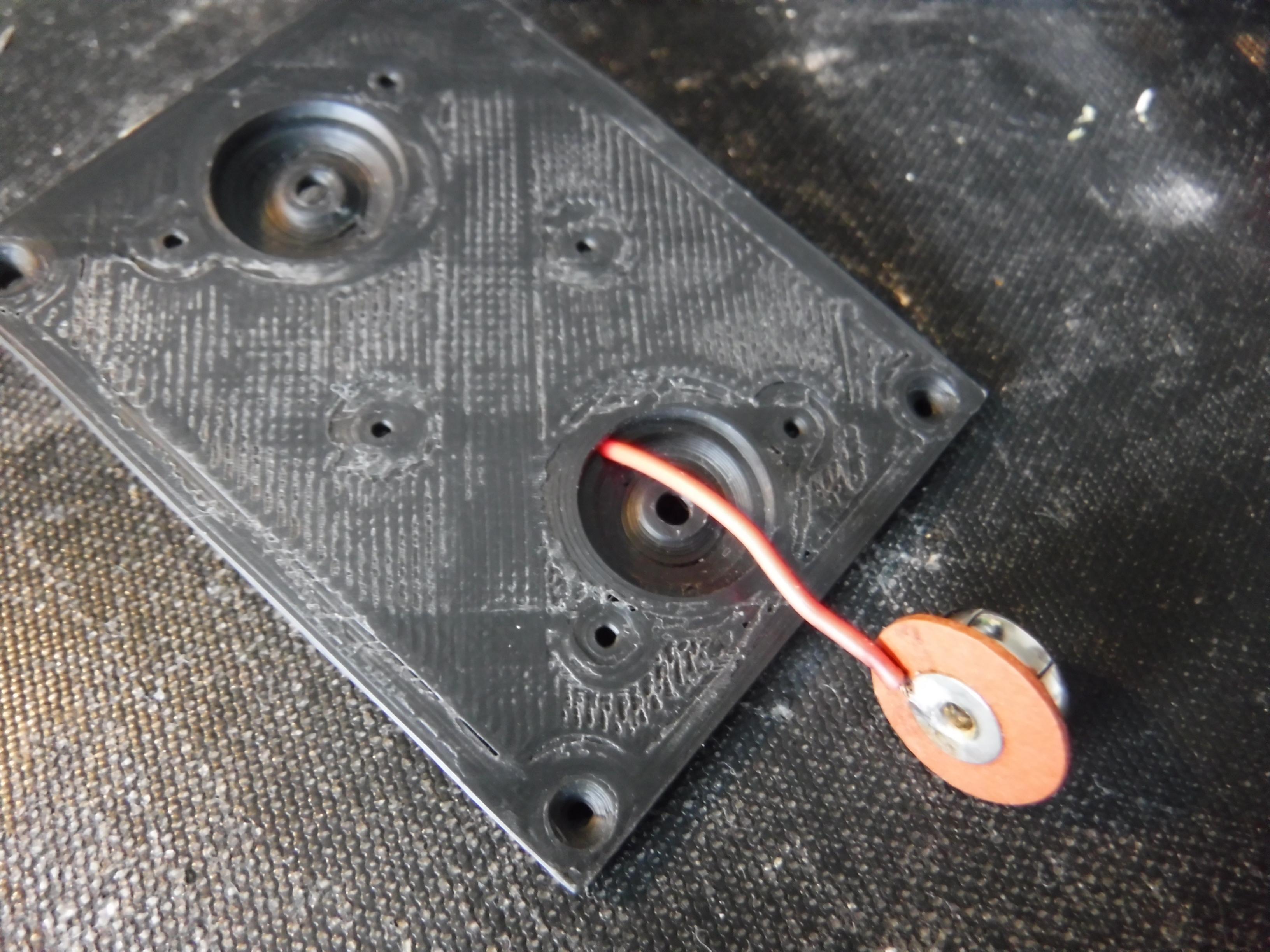
Push the wires for each stud into its 45 degree hole.
Ensure the correct colours and polarity align with the correct stud.
Solder a wire to each stud ensuring the join is as flat as possible but still secure.
Pull the wires back to sit the studs in the circular depressions.
If the stud does not sit flat enough apply a soldering iron tip to the stud centre to melt a little of the underlaying plastic without applying too much pressure.
Once it levels remove the soldering iron and hold it in place whilst it cools with an insulated handle screwdriver.
Repeat the levelling process for the other stud if necessary.
If required clear out the holes in the centre of the studs with a 2mm drill bit.
Ensure the wire sits in the horizontal cavity of the Lid Back and align the fixing holes.
Pass a M2 x 8mm countersunk screw through the centre hole in the stud the Lid and Lid Back aligned with the centre of a nut and tighten.
Repeat for the other stud.
Labelling
The finishing touch is to add the labelling, this and other vintage batteries labels are available at the Royalsignals.* perform a 'Find on page' search for PP9 or scroll down the images until you see PP9.
Print and if necessary scale the file to fit the main body of 63(w) x 50(D) x 77.9(H) mm and cut around the outline.
Use a ruler and blunt scribe to enable neat folds on the main body and tabs.
Reprint and scale the terminal tab to the lid to ensure the text and logo sit with the area 58(W) x 45(D) mm
*No affiliation to this organisation nor the original manufacture or subsiduaries.
Fit the Label


Orientate the label such that the battery terminal tab is at the same end as the open end of the battery Body.
If using adhesive choose one that is flexible that sticks to both paper and plastic.
Apply a little tape or adhesive to the blue tab that is the same height as the Body.
Wrap the label around the body of the battery holder.
Apply adhesive to the top of the blue tab and/or the back of the overlap and press the overlap down.
Apply pressure until the adhesive has set.
Trim ~5mm off the edge of the tab bearing the text "Height-6.25"
Apply adhesive to the taps, fold and press into place and apply pressure until the adhesive has set.
With the open end of the Body uppermost.
Fold the plain short tabs over the lip of the open edge and push down into the corner of the lip with a straight edge and with a sharp blade trim the tab on the inside rim of the lip.
Fold the plain long tab over the lip and in the two corners at the fold close to the lip cut in at a 45 degree angle and press in to the corner of the lip with a straight edge.
Repeat the process applied to the two short tabs.
Fold the battery terminal tab over the lip and repeat the process applied to the long tab.
Apply adhesive to the overlapping paper around the lip and press in place until the adhesive has set.
Cut out the top label to fit centrally with the area of the lid.
Mark the 4 corner and 2 terminal holes with a sharp awl or marker.
Using a paper punch align the centre of the terminal marks previously made with the centre of the punch and cut out the holes.
With a sharp cutting blade make radial cuts around each punched hole to enable the terminals to be pushed through easily.
Apply adhesive to the lid and slip the label over the battery terminals and press in place.
Press the paper to sit flat around the perimeter of each terminal.
Once the adhesive has set, press an awl or 1.5mm drill into the corners of the lid for the M2 screws.
Note: No affiliation to the original manufacture or subsiduaries.
Final Assembly


Press the PP3 connector on to the studs on the battery holder.
Fit 6 x AA or equivalent* batteries correctly orientated into the battery holder.
Ensure the PP3 connector is facing upwards and insert into the Body.
Fit the Lid and secure in place with 4 x M2 x 8mm countersunk screws.
*No affiliation to the manufacturers of the batteries displayed please feel to use any suitable equivalent alternatives.
Finally
You now have a functioning replica of a PP9 battery.
All that is left to do is connect it to that vintage radio or any other appliance or project requiring a 9V battery.