PPS Watch - the Most Accurate Watch That Doesn’t Tell Time
by seanhodgins in Circuits > Electronics
5669 Views, 27 Favorites, 0 Comments
PPS Watch - the Most Accurate Watch That Doesn’t Tell Time
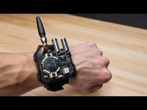
This is a watch that does not tell time.
Which sounds useless, and maybe it is, but it does one very specific thing extremely well: it outputs a GPS-disciplined PPS signal.
PPS stands for “pulse per second,” and it is exactly what it sounds like. Once every second, a GPS module outputs a very accurate timing pulse. Normally you would use this inside test equipment, computers, radio gear, clocks, or other systems that need accurate timing. I decided to put it in a watch.
Mostly because it is funny.
The PPS Watch receives GPS, waits until it has a valid fix, and then outputs the GPS module’s hardware TIMEPULSE signal through a BNC connector. It also accepts an external PPS signal through another BNC connector, compares the two with a hardware XOR phase comparator, and uses LEDs to show what is happening. There is no microcontroller and no firmware. The GPS PPS signal is handled directly with logic buffers and hardware.
It was made as a very silly serious timing accessory for Jeff Geerling.
The watch has:
A GPS PPS output.
An external PPS input.
LEDs for GPS PPS, external PPS, and sync/phase comparison.
A coin cell battery.
A Qwiic port for GPS configuration.
A very questionable lab equipment vibe.
If you have two of these watches, both locked to GPS, they will blink in sync no matter where they are in the world, as long as they can see the sky.
Which is ridiculous.
And cool.
Files are available on GitHub.
Supplies
Source Files and 3D Prints
Hardware
- 2 x M2x6mm Flat Head Plastic Threading Screws to mount body to strap mount. - https://www.mcmaster.com/90485A415/
- 2 x M3x6mm Pan Head Plastic Threading Screws for mounting PCB to Body - https://www.mcmaster.com/99461A939/
- 2 x M3x35mm Round Head Machine Screws to mount strap. Just Thread into the plastic snugly https://www.mcmaster.com/92000A134/
- 1 x 22mm Watch Band -
Tools
- Soldering iron
- Hot air or reflow oven
- Solder paste
- Tweezers
- Small screwdrivers
- 3D printer
- Computer with KiCad / Fusion 360 if modifying the design
- Patience
Understand the Pointless Point of the Watch
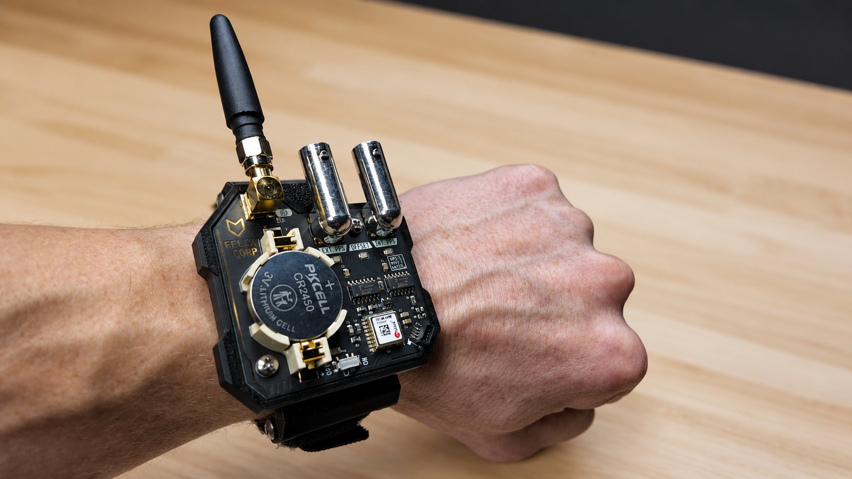
Before building it, it helps to understand what the watch actually does.
This is not a clock display. It does not show hours, minutes, seconds, or anything helpful like that.
Instead, it outputs a 1PPS signal from a GPS module. PPS means one pulse per second. Once the GPS module has a position/time fix, it produces a very accurate pulse every second. That pulse can be used as a timing reference for other equipment.
The watch also has a PPS input. If you plug another PPS signal into the input, the watch compares the external PPS against its own GPS PPS using a hardware XOR gate. If the two pulses are aligned, the sync indicator will show that they are very close. If they are offset, the XOR output gives you a visual indication of the phase difference.
It is basically a tiny GPS-disciplined timing reference.
For your wrist.
Because why not.
Order the Circuit Board and Parts
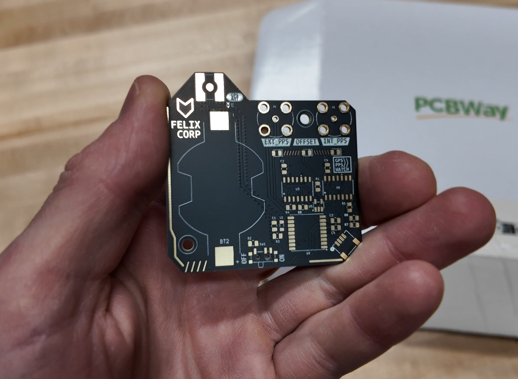
The KiCad files are available in the GitHub repository. The PCB is the main part of the project, and most of the design is built directly around the board. The repo also includes the CAD folder for the printed mechanical parts.
I would recommend ordering the PCB from your preferred PCB manufacturer(PCBWay is my go-to) using the files from the repository. This is a small board, but there are quite a few SMD parts, so you could either assemble it yourself or have the board house assemble it.
3D Print the Watch Body Parts
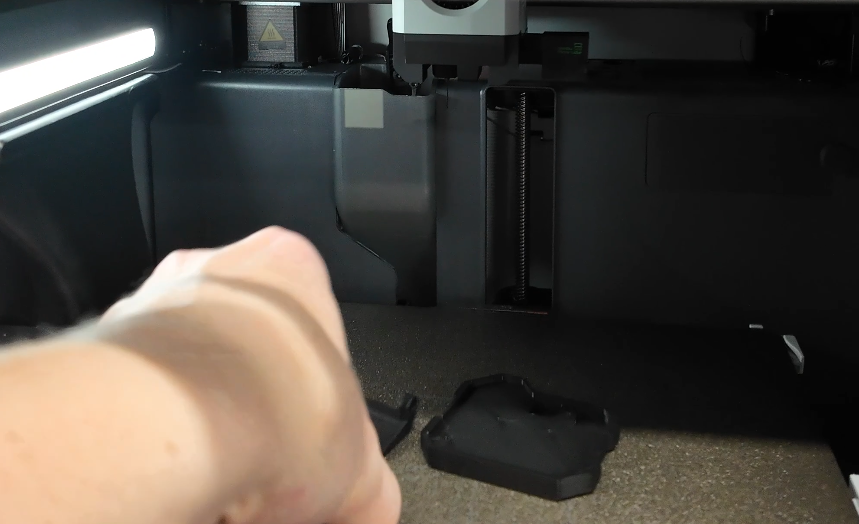
There are two main printed parts in the CAD folder:
pcb_frame_mount.stl
watch_band_mount.stl
The frame holds the PCB, and the band mount lets you attach a normal 22mm watch band. The GitHub notes that any standard 22mm watch band should work, and it was tested with a Bandini nylon sports watch band.
Print the parts with whatever settings work well for your printer. I would avoid anything too flexible because the BNC connectors and SMA antenna connector make this more like wrist-mounted lab equipment than a normal watch.
Apply Solder Paste
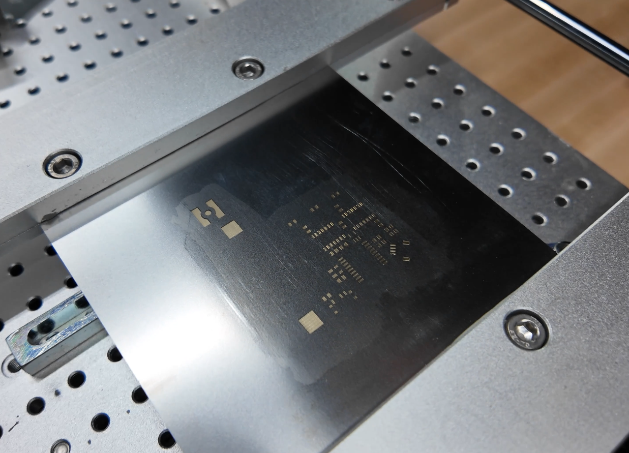
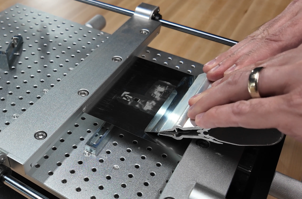
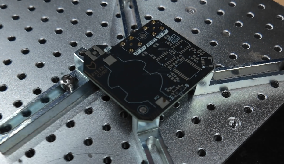
Apply solder paste to the PCB using a stencil.
This is the kind of board where a stencil makes the job much easier. There are a lot of small SMD parts, and the GPS module, logic chips, LEDs, and passives all need to be placed cleanly.
Place the Components
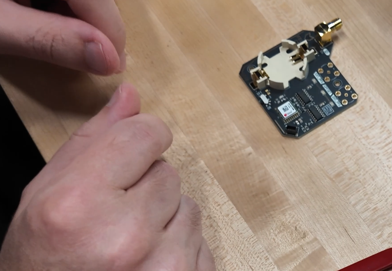
Place the components on the PCB.
Start with the smallest passives first, then move on to the ICs, GPS module, connectors, LEDs, and larger parts.
The main hardware includes a u-blox MAX-M10S GPS module, two 74HC125 quad buffers, and a 74AHC1G86 XOR gate. The buffers handle the GPS output side and external input side, while the XOR gate acts as the phase comparator between the GPS PPS and external PPS.
Pay attention to orientation.
Especially:
- GPS module orientation
- LED polarity
- IC pin 1 markers
- Coin cell holder orientation
The SMA connector is a different SMD version, place that last as its kind of heavy and could easily get knocked off.
This is a good time to stare at the board for a while and convince yourself everything is in the right place.
Then stare at it a little longer.
Reflow the Board
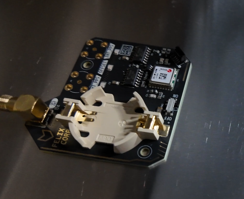
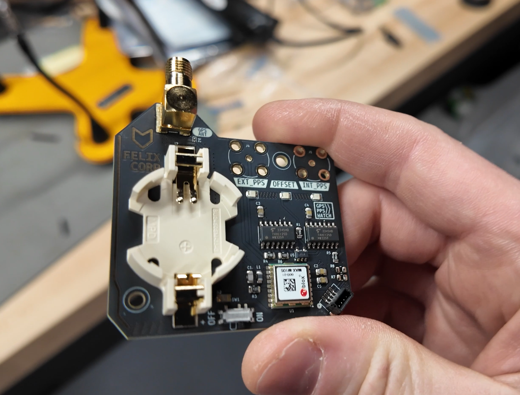
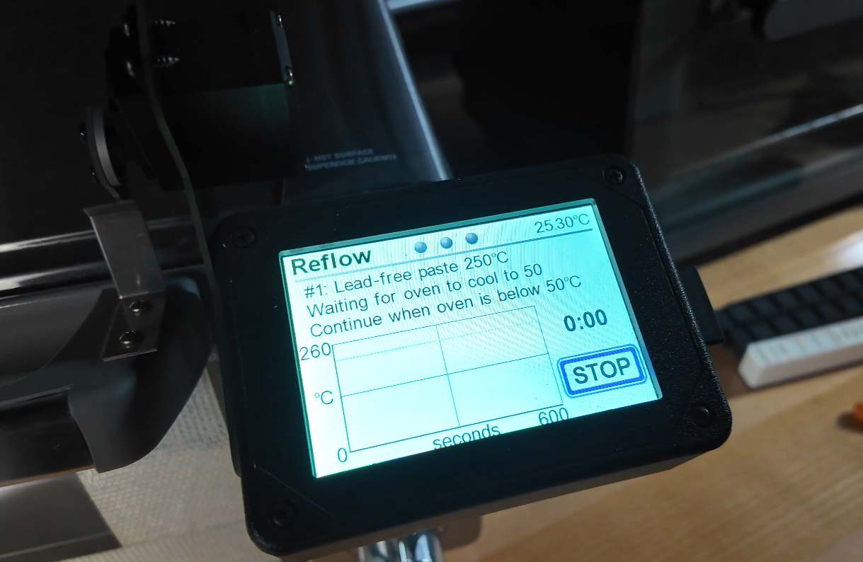
Reflow the PCB.
I still like using a cheap toaster oven for this kind of thing. It is not fancy, but it works. But I recently upgraded to a controleo 3 reflow oven, and its bee working great!
If you're doing it the manual way, watch the board carefully as the solder paste melts. Once everything reflows, let the board cool before touching or moving anything.
After reflow, inspect the board under magnification. Look for:
- Solder bridges
- Tombstoned resistors or capacitors
- Shifted ICs
- Bad joints on the GPS module
- LEDs that moved
- Connectors that are not sitting flat
Fix anything obvious with a soldering iron or hot air.
Install the Through-Hole Parts
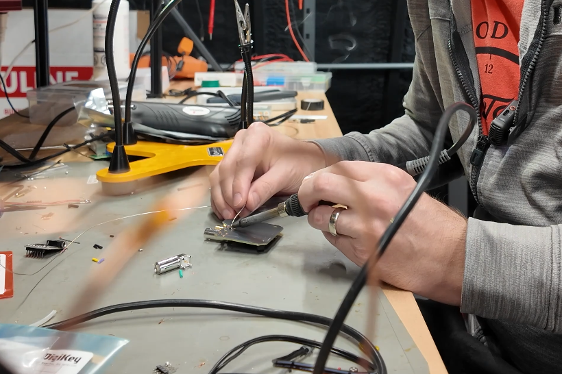
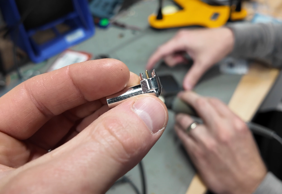
The watch uses two BNC connectors: one for the PPS output and one for the external PPS input. It also uses an SMA connector for the external GPS antenna.
The BNC connector have a lot of thermal capacity, and will need a lot of heat to get them to solder.
Assemble the Watch
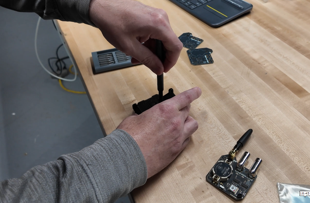
Mount the PCB into the 3D printed frame.
- 2x M2x6mm flat head plastic threading screws to mount the body to the strap mount
- 2x M3x6mm pan head plastic threading screws for mounting the PCB to the body
- 2x M3x35mm round head machine screws to mount the strap
Install the watch band mount, then attach the 22mm watch band.
Do not overtighten the screws. You are threading into plastic, and the PCB is still a PCB.
Get a GPS Fix
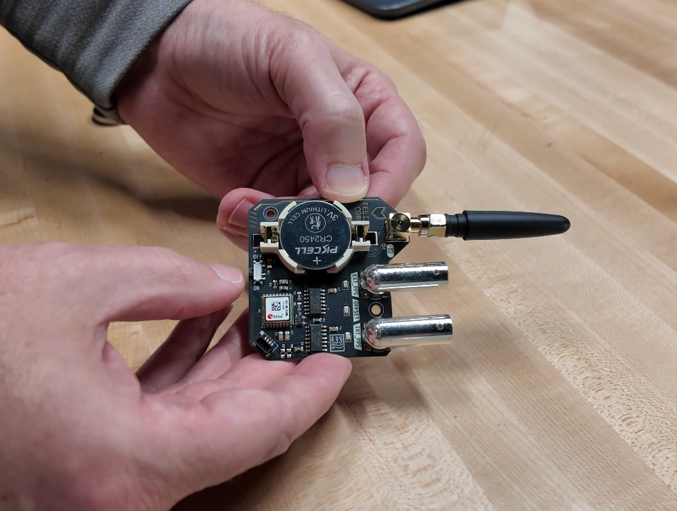
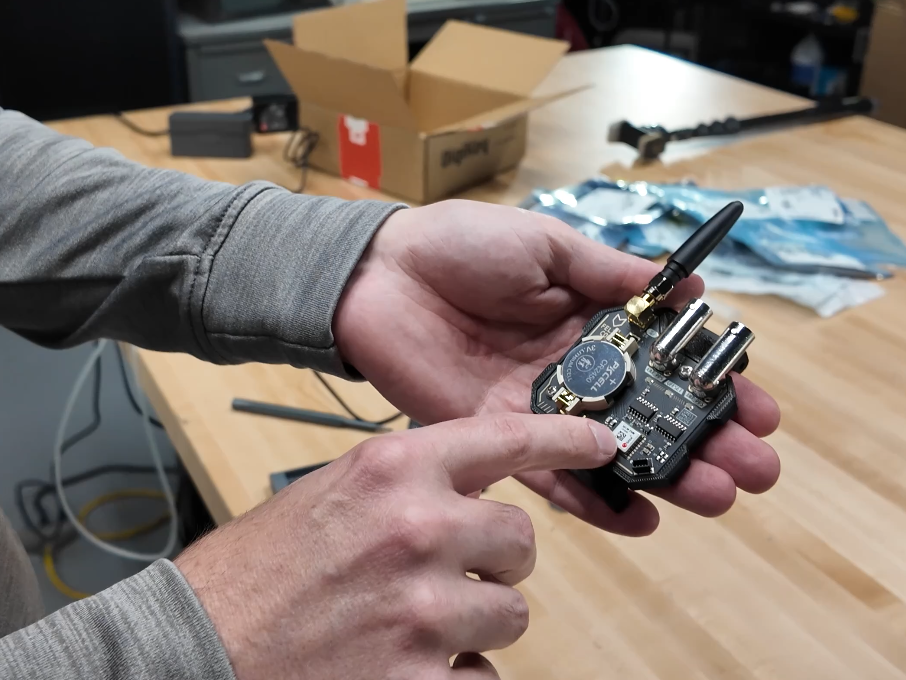
Connect the GPS antenna to the SMA connector.
The design uses an external antenna through SMA, with no onboard antenna.
Take the watch somewhere with a clear view of the sky.
Wait for the GPS module to get a fix.
Once locked, the GPS module outputs its hardware PPS signal at 1Hz. Until it is locked, the PPS output is silent. This is nice because the watch only outputs a useful pulse when GPS timing is valid.
One LED shows GPS PPS activity. Another LED shows the external PPS input if one is connected. The sync LED gives a visual indication of how close the two signals are. The "offset" LED will blink with the PPS pin when no external PPS is present.
Test the PPS Output
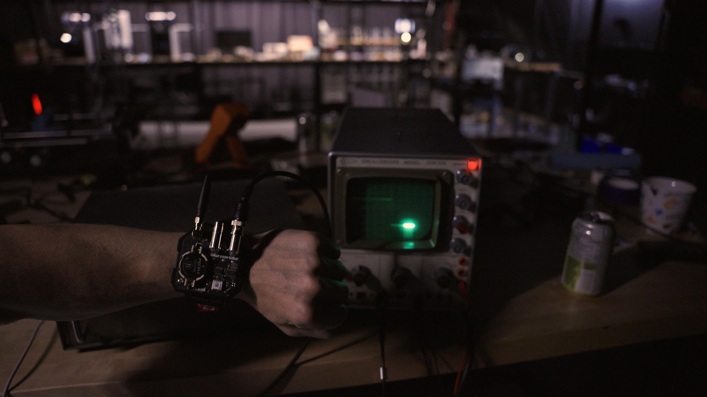
Connect the PPS output BNC to something that can show the signal.
An oscilloscope is ideal.
Once the GPS has a fix, you should see a clean pulse once per second on the output. This is the whole reason the watch exists.
You can also connect it to equipment that accepts an external PPS timing reference, but I would test it on a scope first. It is easier to see what is happening.
At this point you have a working watch.
It still does not tell time.
Perfect.
Test the External PPS Input
Now connect an external PPS source to the input BNC.
This could be another GPS timing source, another PPS Watch, or any other clean 1Hz PPS reference.
The external PPS LED should blink when the input signal is present.
The watch compares the external PPS signal to its own GPS PPS signal using the XOR phase comparator. If the pulses are very close together, the sync indicator should show that they are aligned. If they are offset, the comparator output changes accordingly.
This makes the watch a tiny visual PPS comparison tool.
Which is the kind of thing no normal person needs.
So naturally I made it wearable.
Sync Two Watches
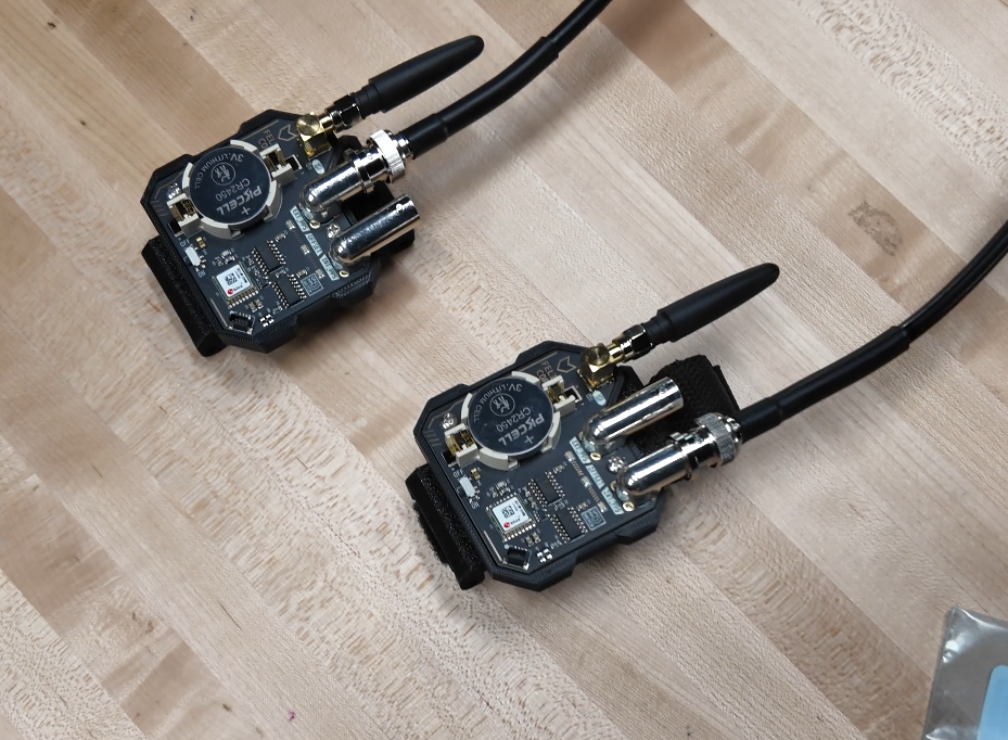
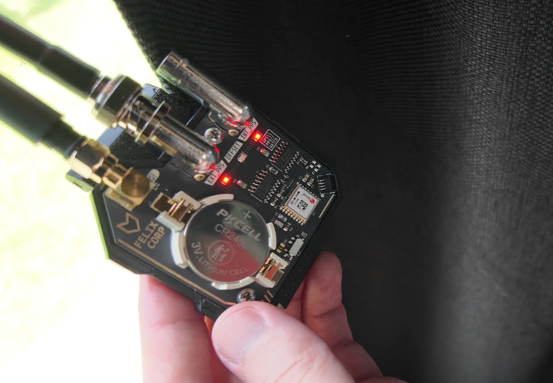
The best demo is with two PPS Watches.
Phone a friend with a similar obsession with time.
Take both watches outside, install antennas, and let both GPS modules lock.
Once both watches have GPS fix, their PPS LEDs should blink together. Since both are disciplined by GPS time, they should remain synchronized even if they are far apart, as long as each watch has a good GPS signal.
You can also connect the PPS output from one watch into the PPS input of the other watch. Then the second watch can compare its own GPS PPS against the incoming PPS from the first watch.
This is where the project becomes weirdly satisfying.
Wear Your Useless Timing Reference

You can now wear the PPS Watch.
It has BNC connectors.
It has a GPS antenna.
It does not tell time.
But it does output an accurate PPS signal, compare another PPS signal, and look like something stolen from the lab of a cheesy sci-fi show.
That is really all I wanted.
Thanks!
Thanks for checking out the project.
All of the design files are available on GitHub, including the KiCad project, CAD files, BOM, and assembly notes.
If you want to support more weird open source projects like this, subscribe to my YouTube channels:
And consider becoming a Patron.