PT2314 Based 4-Channel Digital Audio Processor
by Electroveins in Circuits > Audio
187 Views, 0 Favorites, 0 Comments
PT2314 Based 4-Channel Digital Audio Processor
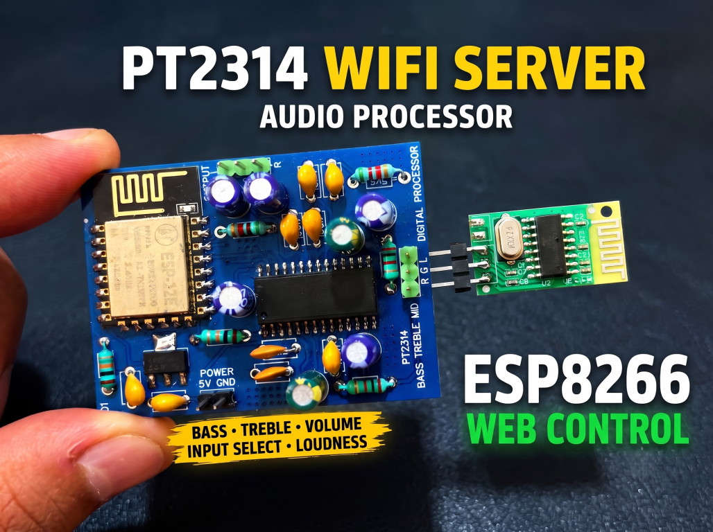
Connect the bluetooth to stream the audio and connect the WIFI to control it from the same device.
Supplies
Components Required
Here is the list of components I used for this build. All designators match my EasyEDA schematic:
- PT2314E audio processor IC (DIP-28)
- ESP-12E (ESP8266 module)
- AMS1117-3.3 voltage regulator
- 2.2 uF electrolytic (audio input coupling)
- 10 uF electrolytic (input filtering, reference, output coupling)
- 100 nF ceramic (bass/loudness network, decoupling)
- 2.2 nF ceramic (treble filter)
- 2.2K (audio input series resistors)
- 5.6K (bass feedback network)
- 10K (ESP-12E pull-ups)
- 6-pin programming header (RX, TX, RST, IO0, 3V3, GND)
- 2-pin power connector (5V + GND)
- 3-pin output connector (LOUT, ROUT, GND)
- 3-pin input connector (LIN, RIN, GND)
Story:
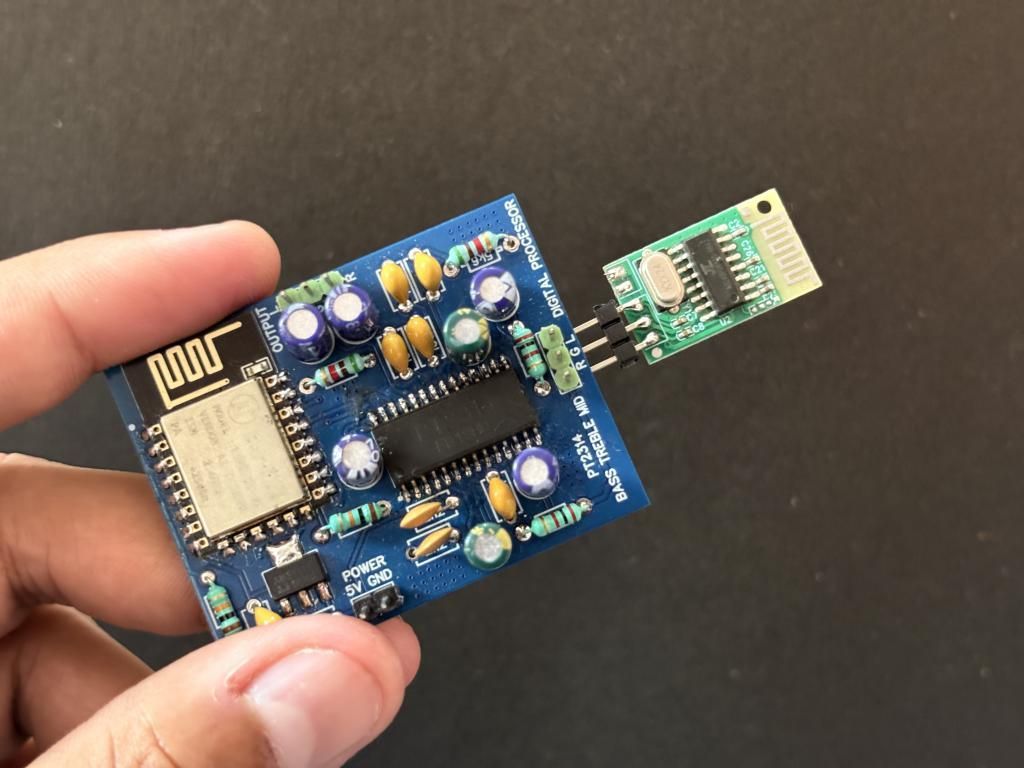
DSPs, but from back in the 2005 era, have their own old-school vibe. Honestly, I am not amazed because we(creators) almost ran a series on it, from starting back from PT2258, PT2315, and now I have cam with PT2314 firmware and hardware. The PT series is very famous, and we want to cover all of them because there are very few resources, some are selling their libraries, and this one came with a single Arduino code. The second problem I found with most online resources is that the front-end circuitry is very intensive, so I moved everything to an HTML script. I handled the controls on a web server instead of using volume knobs for different things. Which will reduce the overhead cost of front end electronics.
You open a webpage, adjust volume, bass, treble, switch inputs, change gain, and everything is accessible from your phone. The settings are saved in EEPROM, so even after a power cycle, the last configuration stays the same. I have designed a dedicated PCB using this idea, with an onboard ESP8266. All the files for this project are open-sourced and can be downloaded directly from GitHub. I had fabricated it using the JLCPCB's PCB manufacturing service for just $2. All the designed files are attached here with the code and audio testing tutorial below.
What Is PT2314?
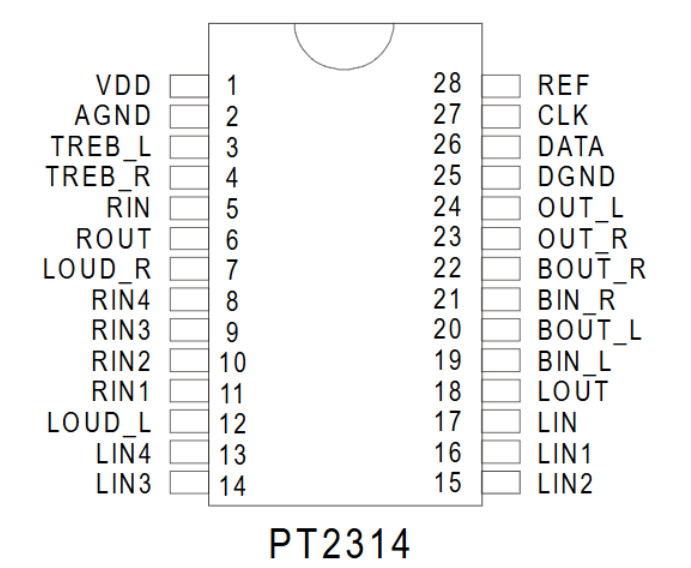
The PT2314 is a 4-channel audio processor IC from Princeton Technology. It is pin-compatible with the TDA7314 from ST Microelectronics. The IC handles all audio processing internally, including volume, bass, treble, speaker attenuation, input selection, and loudness, over the I2C bus. Here is what makes it interesting compared to the PT2315:
- 4 stereo input channels
- Input gain control: 4 levels (0, +3.75, +7.5, +11.25 dB)
- Volume range: 0 to -78.75 dB with 1.25 dB fine steps and 10 dB coarse steps
- Bass and Treble: -14 to +14 dB in 2 dB steps
- Independent speaker attenuators: L and R attenuation 0 to -38.75 dB
The IC operates at a 7.5V to 9V supply and communicates over I2C at address 0x44 (7-bit). It needs minimal external components, just a few coupling capacitors on the audio paths and pull-up resistors on the I2C lines. See the schematics section for more info.
Circuit Diagram and Schematic
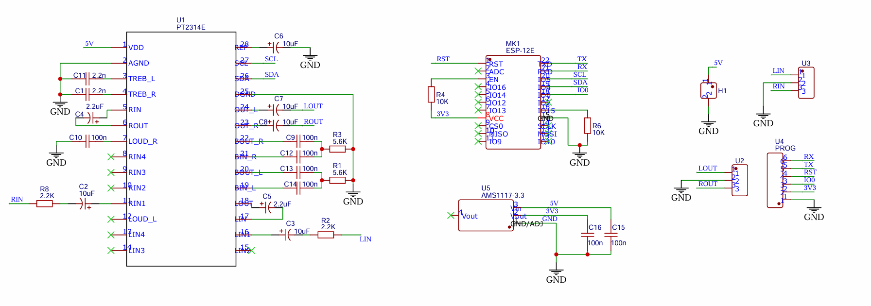
The board runs on a single 9V DC supply and for the ESP8266 2e need 3.3V, which the onboard LDO converts down. There are a few decoupling capacitors for power rails. The PT2314E has two ground pins: Pin 2 (AGND) for the analog section and Pin 25 (DGND), which are then joined together using a single connection.
In the PCB layout, I route them carefully to avoid digital noise coupling into the analog audio path. To keep the ESP in programming mode, pull-up resistors are used to pull the pins high. You can find a full tutorial on programming the ESP8266 using an external controller. In the input-output section, proper filtering is implemented using a combination of resistors and capacitors. I used the same application circuit recommended in the datasheet, just added some features for the web server, so nothing fancy.
Tone Control Network
The PT2314E has external filter components for the bass and treble processing. For the treble network we have, two 2.2 nF ceramic capacitors, TREB_L and TREB_R, both go to ground, and these set the treble shelving filter frequency. For the bass here, a feedback network is used; each channel has a 5.6K resistor and a 100 nF capacitor between the BIN and BOUT pins. These components define the bass boost/cut frequency response. In the loudness option, a 100 nF capacitor connects from LOUD_R to ground. This capacitor is part of the loudness compensation network inside the IC.
PCB Design:
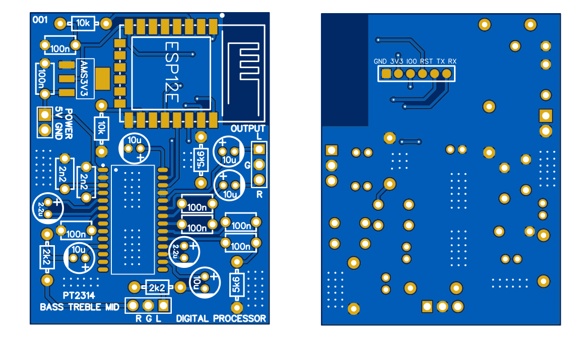
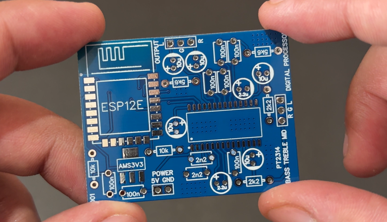
I want to keep the system minimal, the reason is that there are analogue and digital parts that are on the same circuit board. The digital data travel through SCL and SDA lines which may cause problem in audio, so we should follow proper guidelines. The best thing is to route these digital signals away from any analogue signal and surround them with ground planes.
For the assembly, because I have used mainly the THT components, which can be soldered by hand, moreover, only the ESP8266, 3V3 regulator and PT2314 are using SMD pads, where you may get some issues. Still, I always recommend soldering the SMD first, then moving to the THTs, and finally to the header part. In this way, with minimum time and effort, you can solder this board.
The same is implemented here in the design; I use ground fills on both layers, which can be connected with vias and ground stitches. Moreover, the LDO is in the middle, powering the ESP8266, and all other systems run at 5V. The signal may get interference if the supply used is SMPS, so try to go with batteries or a good power adapter with EMI shielding to reduce the overall noise. And I got fabricated 5 of them from JLCPCB, because they have a good integration with EasyEDA, I never feel any difficulties in order.
PT2314 I2C Register Mapping
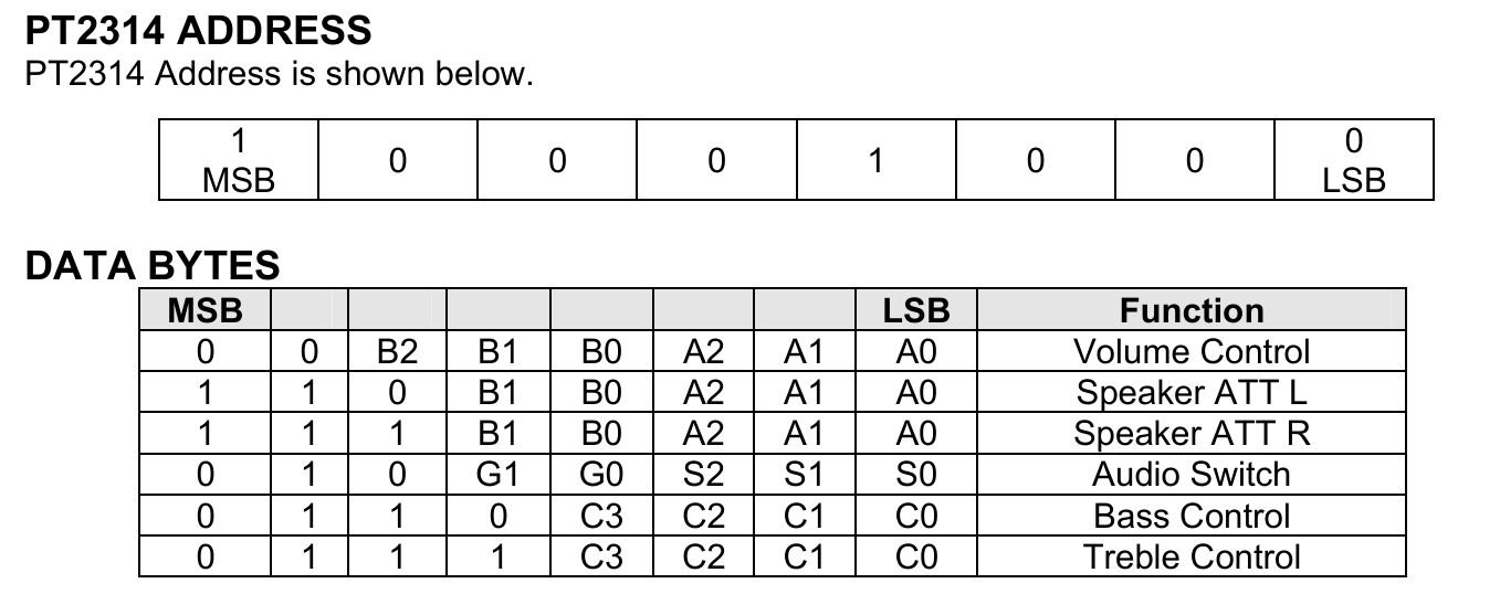
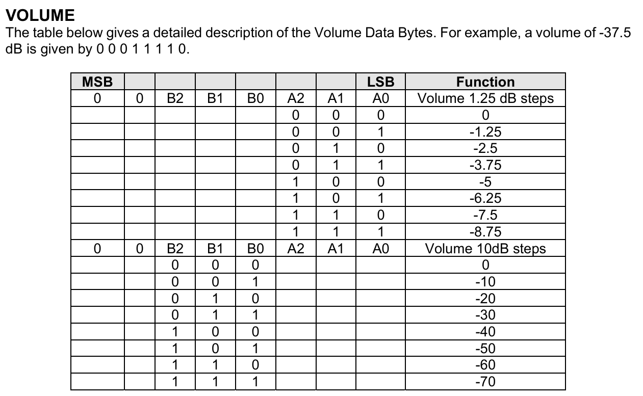
The PT2314 is controlled by writing single bytes over I2C. We have to send the values to the registers to set the tone. This value is provided by the ESP8266's I2C bus. Here is an example for the volume register, byte: 00 BBB AAA. The two MSBs are always 0. The next 3 bits (B) set the 10 dB step attenuation (0 to -70 dB). The last 3 bits (A) set the 1.25 dB step attenuation (0 to -8.75 dB). Total attenuation is given by = B x 10 + A x 1.25. Sending 0x3F provides maximum attenuation, effectively muting. The same process applies to other registers; let's see how the code works and how to send these bytes using the Arduino internal wire library. For a better understanding of the register map, just look into the datasheet of that specific function.
Code Working
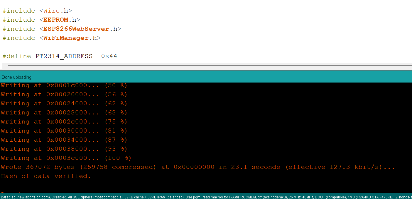
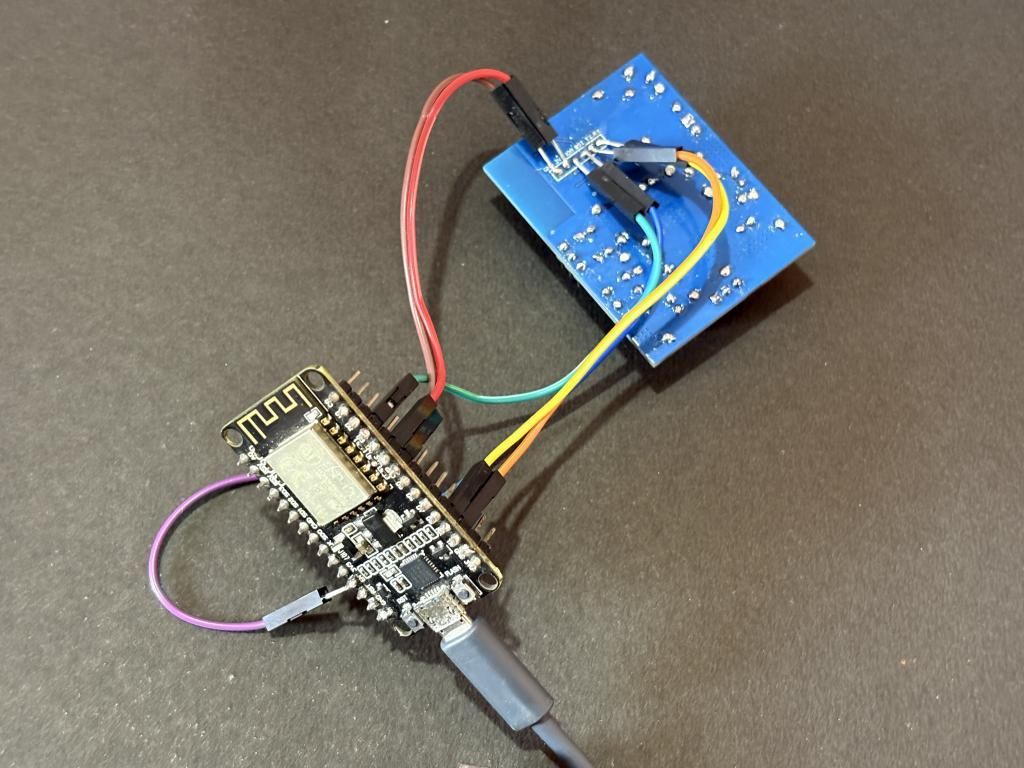
The firmware is built on four libraries:
- Wire.h
- EEPROM.h
- ESP8266WebServer.h
- WiFiManager.h
And these libraries are free and open-sourced; you can find them in the library section of the Arduino IDE. Here is how data is transferred over the I2C line. We are using the wire library functionality:
The I2C address is 0x44 (7-bit). The Wire library handles the R/W bit automatically, so the actual byte on the bus becomes 0x88 for write operations.
Volume accepts values 0 to 63. Value 0 is the loudest (0 dB attenuation) and 63 is the quietest (-78.75 dB). For mute, I simply send 0x3F, which sets maximum attenuation. The PCB features programming headers on the bottom layer, where all connections are made to another ESP8266, allowing for programming to be done. To see the step-by-step programming tutorial, please refer to this link.
Web Server Interface
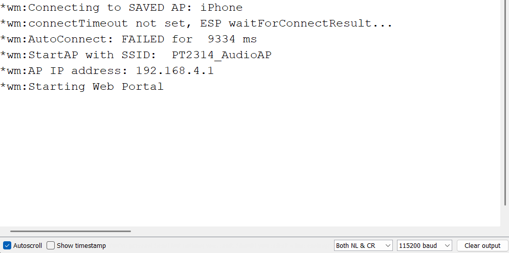
On first boot, the ESP8266 creates a Wi-Fi access point named PT2314_AudioAP with password 12345678. Connect to it from your phone's Wi-Fi, filling in the password.
Image 1
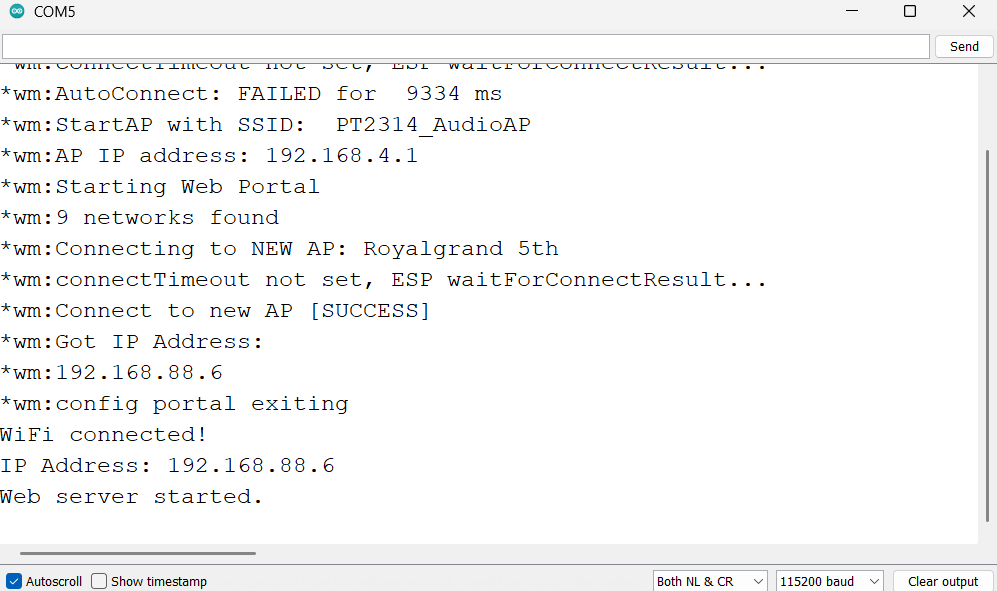
And a captive portal opens where you select your home WiFi network. After connecting, the serial monitor shows the IP address and opens it in any browser.
Image 2
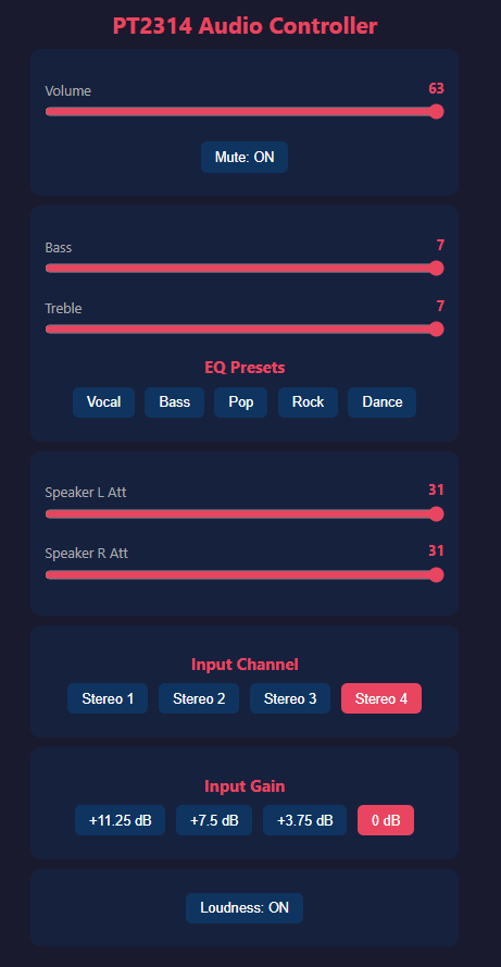
The web UI has a dark theme, have a look here: image 3
Some preset modes select a constant bass and table values. You can see them in the UI, and the preset values are arranged like:
- Vocal: Bass 0, Treble +3
- Bass Boost: Bass +5, Treble -1
- Pop: Bass +1, Treble +2
- Rock: Bass +3, Treble +3
- Dance: Bass +4, Treble +4
All controls update in real-time, just move a slider and the audio changes instantly. No page reload needed for sliders and toggles. The preset and input buttons do a quick reload to update the UI state. The UI is strong but can be handled easily on an ESP8266 web server.
POP Noise of the System
If you hear a pop or click when switching inputs or adjusting volume, that is normal for this class of ICs. The pop comes from the internal switching of analog paths. If you are feeding this into a power amplifier, make sure the amplifier has proper input filtering or a mute-on-startup circuit. Avoid connecting tweeters directly because they are very sensitive to transient spikes. Using a clean power supply significantly reduces the pop. Battery power gives the best results. If you must use an SMPS, add extra filtering on the supply rail.
Testing With Class-D Amplifier and Bluetooth
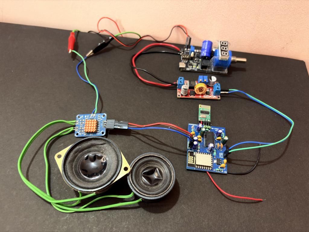
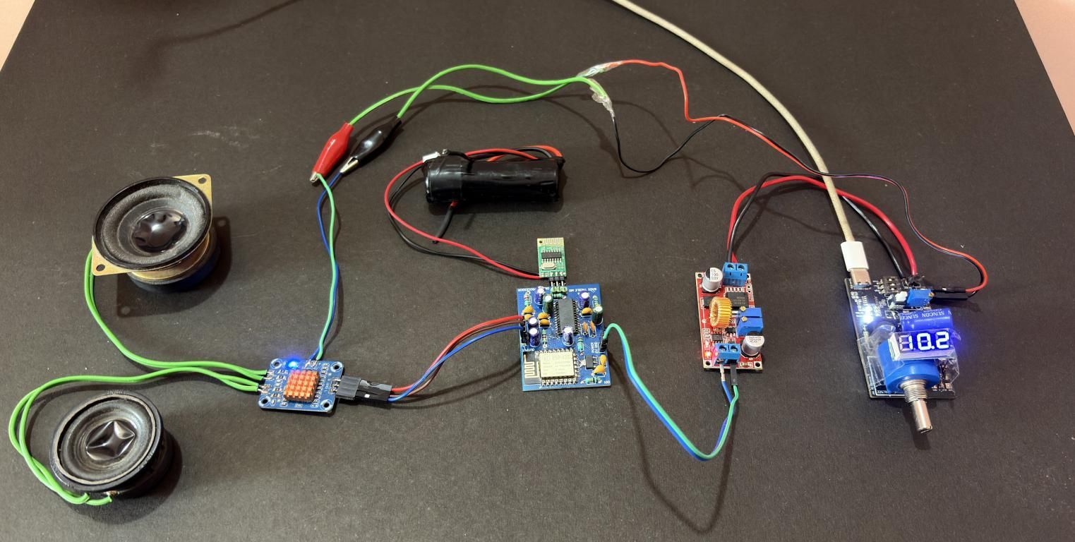
Now, to test the PT2314, I have arranged two small speakers with a small Class-D amplifier board. The audio source was an external Bluetooth module connected to the Stereo 1 input, which is then connected to the mobile to stream the audio. I can play music from my phone over Bluetooth and control volume, bass, treble, and input gain in a separate browser tab on the same mobile device. The Bluetooth module outputs a slightly weaker signal than a direct AUX connection, so bumping the gain to +7.5 dB matches the levels nicely.
Audio quality is clean with no audible noise floor at normal listening levels. At very high volume with bass boost maxed, the Class-D amp handles it without clipping. The only thing to watch is the POP noise on power-up. Make sure the amplifier has a mute-on-startup feature or add a small delay relay on the speaker outputs. Or we can use a speaker protection circuit as an add-on. I have recorded the full video on the same; as an audio test.
Outro
So, this project provided a valuable learning experience. Now, the only IC left to cover is in the PT series. I will post the article on that also very soon, stay tuned for that! With this, the PT2314 with an ESP8266 can be a complete setup for audio streaming with a controller. Everything can be controlled from a single mobile device. This gives it a performance and feature boost. Code is open source to all members. You can order the PCB and download the attached resources. I am happy to answer any query. The comment section is free for your feedback!